14 TISSUE MANAGEMENT AND IMPRESSION MAKING
Because it is neither possible nor desirable to make patterns for fixed prostheses directly in the mouth, an impression, or negative likeness of the teeth and surrounding structures, is necessary to obtain a cast. This cast is then used to make a restoration in the laboratory. To obtain the cast, an elastic impression material is mixed and loaded in a tray that is inserted into the patient’s mouth. When the material has set, it remains elastic; the impression is then poured into the “negative” impression, and a positive likeness or definitive cast is obtained.
An acceptable impression must be an exact record of all aspects of the prepared tooth. This means it must include sufficient unprepared tooth structure immediately adjacent to the margins for the dentist and laboratory technician to identify the contour of the tooth and all prepared surfaces. The contour of the unprepared tooth structure cervical to the preparation margin is crucial information that must be available when the restoration is fabricated in the dental laboratory. If the impression does not reproduce this critical area where tooth and future restoration meet, fabricating the restoration with proper contours is not possible (barring some lucky guesswork).
All teeth in the arch and the soft tissues immediately surrounding the tooth preparation must also be reproduced in the impression. They allow the cast to be accurately articulated and contribute to proper contouring of the planned restoration. Particular attention is given to reproducing the lingual surfaces of anterior teeth because they influence anterior guidance, which determines the occlusal structure of the posterior teeth (see Chapter 4). The impression must be free of air bubbles, tears, thin spots, and other imperfections that might produce inaccuracies.
The patient’s mouth is a challenging environment in which to make an accurate impression. Moisture control is probably one of the most important aspects of successful impression making. Except for the polyethers, all elastomeric impression materials are hydrophobic1 (i.e., they do not tolerate or displace moisture). Any moisture results in voids. Consequently, saliva flow into the area must be reduced and diverted to obtain the necessary dry field of operation. Any bleeding must also be controlled in order to obtain a successful impression.
When the preparation margins extend subgingivally, the adjacent gingival tissues must be displaced laterally to allow access and to provide space for adequate impression material thickness. This may require enlarging the gingival sulcus through mechanical, chemical, or surgical means and must be done without jeopardizing periodontal health. Improper manipulation of impression material and poor tissue displacement technique can lead to permanent soft tissue damage.
PREREQUISITES
Tissue Health
After the teeth are prepared and an interim restoration has been made (see Chapter 15), the health of the surrounding soft tissues must be reevaluated. Careful preparation results in minimal tissue damage; however, if a subgingival margin is needed, some tissue trauma in the sulcular area may be unavoidable. The effects of this trauma can be transient as long as the patient receives a properly made interim restoration and maintains adequate oral hygiene. However, if the interim restoration is poorly contoured, is not polished, or has defective margins, plaque retention will lead to a localized inflammatory response. The combination of such tissue trauma in the presence of preexisting periodontal disease can produce disastrous results. Periodontal disease must be treated and resolved before fixed prostheses are placed.
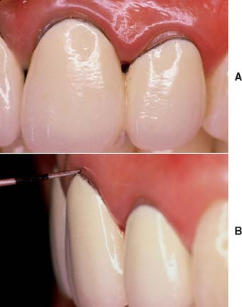
On occasion, a defective restoration contributes to greater plaque accumulation2 and an inflammatory sulcular response (Fig. 14-1). If this is the case, a properly adapted and well-contoured polished interim restoration must be fabricated and cemented on the prepared teeth; the focus must shift from the teeth to the soft tissues, which must be returned to a state of optimum health before impression making is even considered.
Saliva Control
Depending on the location of the preparations in the dental arch, several techniques can be used to create the necessary dry field of operation (Fig. 14-2). In areas where only supragingival margins are present, moisture control with a rubber dam is probably the most effective method. In most instances, however, a rubber dam cannot be used, and absorbent cotton rolls must be placed at the source of the saliva; an evacuator must be placed where the saliva pools. In the maxillary arch, placing a single cotton roll in the vestibule immediately buccal to the preparation and a saliva evacuator in the opposing lingual sulcus is usually sufficient. When work is being done on a maxillary second or third molar, multiple cotton rolls must sometimes be placed immediately buccal to the preparation and slightly anterior to block off the parotid duct, which opens just anterior to the maxillary first molar. If a maxillary roll does not stay in position but slips down, it can be retained with a finger or the mouth mirror. When a mandibular impression is made, placement of additional cotton rolls to block off the sublingual and submandibular salivary ducts is usually necessary. Rolls on the buccal and lingual sides of the prepared teeth help with soft tissue retraction: the cotton on the buccal side displaces the cheek laterally, and the cotton on the lingual side displaces the tongue medially. One or two cotton rolls placed vertically between the horizontally placed cotton rolls in the buccal vestibules help maintain the latter in position.
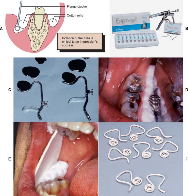
Fig. 14-2 Saliva control for impression making. A, When correctly placed, maxillary cotton rolls block salivary flow from the parotid gland. The evacuator removes saliva from the floor of the mouth, keeping the prepared tooth dry while the flange displaces the tongue medially. B, Expa-syl is a paste used for gingival retraction that opens the sulcus, physically displacing the tissue and leaving the field dry, ready for impression taking or cementation. C, Svedopter (left) and Speejector (right) saliva evacuators. D, Placement of the Svedopter with cotton rolls. E, An absorbent card. F, The disposable Hygoformic aspirator system.
(B, Courtesy of Kerr Dentistry, Orange, California; F, courtesy of Sullivan—Schein Dental, West Allis, Wisconsin.)
An alternative to multiple cotton rolls is placement of one long roll “horseshoe fashion” in the maxillary and mandibular mucobuccal folds. However, when part of the cotton is saturated, the entire roll must be replaced. The use of moisture-absorbing cards (see Fig. 14-2E) is another method for controlling saliva flow. These cards are pressed-paper wafers that may be covered with a reflective foil on one side. The paper side is placed against the dried buccal tissue and adheres to it. In addition, two cotton rolls should be placed in the maxillary and mandibular vestibules to control saliva and displace the cheek laterally.
The tongue can cause problems when work is being done in the mandibular arch. Saliva evacuators may help eliminate excess flow, but most of these are easily displaced by a “probing” tongue. If lingually placed cotton rolls continually become dislodged or, in conjunction with a conventional saliva evacuator, fail to control moisture adequately, a flange-type evacuator (e.g., the Svedopter* or the Speejector†) should be considered (see Fig. 14-2C). To avoid the risk of soft tissue trauma, this device must be placed carefully. A cotton roll between the blade and the mylohyoid ridge of the alveolar process minimizes intraoral patient discomfort. Simultaneously, if properly positioned, the cotton roll provides a “stop” that prevents the flange from being displaced farther buccally and thereby allows excellent lingual access to mandibular posterior teeth. Care must be taken not to tighten the chin clamp excessively, because considerable discomfort can result from pressure to the floor of the mouth. A disposable saliva ejector designed to displace the tongue may also be effective (see Fig. 14-2F).
In addition to the pain control normally needed during tissue displacement, local anesthesia may help considerably with saliva control during impression making. Nerve impulses from the periodontal ligament form part of the mechanism that regulates saliva flow; when these are blocked by the anesthetic, saliva production is considerably reduced.
When saliva control is especially difficult, a medication with antisialagogic action may be considered (Table 14-1). Dry mouth is a side effect of certain anticholinergics3,4 (drugs that inhibit parasympathetic innervation and thereby reduce secretions, including saliva). This group of drugs includes atropine, dicyclomine, and propantheline. Anticholinergics should be prescribed with caution in older adults and should not be used in any patient with heart disease. They are also contraindicated in individuals with glaucoma, because they can cause permanent blindness. The incidence of undiagnosed glaucoma in the general population is high, and some physicians recommend that all patients be evaluated ophthalmologically before anticholinergics are used.
Table 14-1 MEDICATIONS WITH ANTISIALAGOGIC EFFECT*
| Brand name | Active ingredient | Dosage |
|---|---|---|
| Pro-Banthine | Propantheline bromide | 7.5–15 mg |
| Robinul (Robinul Forte) | Glycopyrrolate | 1–2 mg |
| Sal-Tropine | Atropine sulfate | 0.4 mg |
| Antipas, Bentyl | Dicyclomine HCl | 10–20 mg |
* Given 30–60 minutes before drying effect is required. (Individual dosage should be adjusted in keeping with most recent guidelines.)
Clonidine,5 an antihypertensive drug, has successfully reduced salivary output. It is considered safer than anticholinergics and has no specified contraindications. However, it should be used cautiously in patients who take hypertension medication. In a clinical trial,6 0.2 mg of clonidine reduced salivary flow as effectively as 50 mg of methantheline.
Displacement of Gingival Tissues
Tissue displacement is commonly needed to obtain adequate access to the prepared tooth to expose all necessary surfaces, both prepared and not prepared. This can be achieved by mechanical, chemical, or surgical means.
Mechanical displacement is most effectively achieved by placement of a cord (Fig. 14-3) (generally impregnated with a chemical agent). Alternatively, paste systems can be used, often in conjunction with directed pressure. Chemicals such as aluminum sulfate or epinephrine cause localized soft tissue shrinkage. Surgical tissue removal can be accomplished through curettage, excision with a scalpel, or electrosurgery.
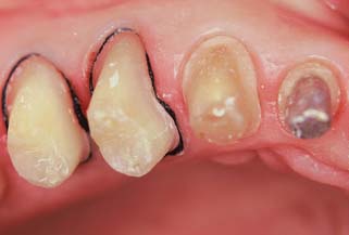
Fig. 14-3 Cord has been placed intrasulcularly as close to the level of the prepared margin as possible to displace tissue laterally.
Displacement cord
Some enlargement of the gingival sulcus can be obtained by placing a nonimpregnated cord and leaving it in place for a sufficient length of time. The cord is pushed into the sulcus and mechanically stretches the circumferential periodontal fibers. Placement is often easier if a braided cord (e.g., GingiBraid)* or a knitted cord (e.g., Ultrapak†) is used. However, larger sizes of braided cord should be avoided because they have a tendency to “double up” and can become too thick for atraumatic intrasulcular placement. In areas where very narrow sulci preclude placement of the smaller sizes of twisted or braided cord, wool-like cords that can be flattened are preferable for initial displacement of tissue.
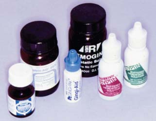
Better sulcus enlargement can be achieved with a chemically impregnated cord or by dipping the cord in an astringent (e.g., Hemodent‡). These materials (Fig. 14-4) contain aluminum or iron salts and cause a transient ischemia, shrinking the gingival tissue. Cords with metal filament reinforcement have been developed to help maintain their intrasulcular position.
Even so, the sulcus closes quickly (less than 30 seconds) after the cord is removed; therefore, the impression must be taken immediately.7 In addition, medicaments help control seepage of gingival fluid. Aluminum chloride (AlCl3) and ferric sulfate [Fe2(SO4)3] are suitable because they cause minimal tissue damage. As an alternative, a sympathomimetic amine-containing eye wash§ or nasal decongestant¶ has been shown to be effective.8
Many of the chemicals used for their astringent effect are stable only at narrow ranges of low pH levels. Table 14-2 shows the mean pH of some commonly used materials. The low pH levels have raised concern about the effect of acidic solutions on tooth structure and, perhaps of more importance, on the smear layer.9,10 Figure 14-5 represents scanning electron micrographs of dentin after various durations of exposure to a commonly used ferric sulfate solution. Contact between the astringent and the prepared tooth surfaces must be minimized if the smear layer is to be maintained. A nonacidic hemostatic agent can be used as an alternative.
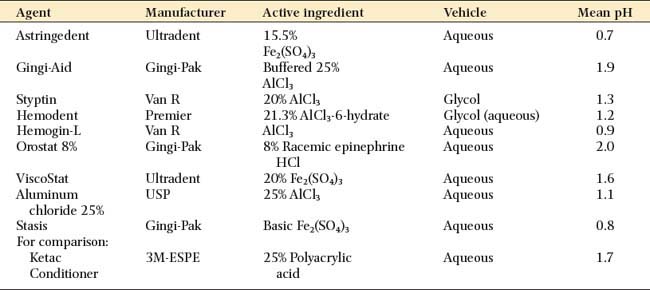
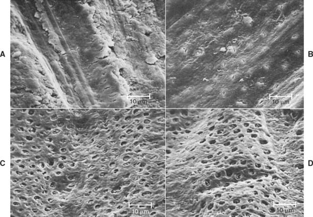
Fig. 14-5 Disturbance of the dentinal smear layer after contact with hemostatic agents. A, Dentin surface prepared with a high-speed, fine-grit diamond. B, After exposure to 15.5% Fe2(SO4)3 solution for 30 seconds. The smear layer is largely removed, but many dentinal tubules are still occluded. C, After 2 minutes of exposure. Now the smear layer is totally removed, although the peritubular dentin appears to be largely intact. D, After 5 minutes of exposure. Now the dentin is etched, and peritubular dentin has been largely removed.
(From Land MF, et al: Disturbance of the dentinal smear layer by acidic hemostatic agents. J Prosthet Dent 72:4, 1994.)
Several displacement cords preimpregnated with epinephrine are available commercially. Epinephrine should be used with caution, because it may cause tachycardia,11 particularly if it is placed on lacerated tissue. Dosage control is also a potential problem. In one study,12 clinicians were unable to detect any advantages of using gingival retraction cords that were impregnated with epinephrine.
A 1999 survey determined that 54% of prosthodontists prefer use of buffered AlCl3 to soak displacement cord, whereas more than 35% routinely use ferric sulfate or aluminum.13 The same researchers reported use of a double-cord technique in almost half of the clinical situations. With this technique, a thin cord is placed without overlap at the bottom of the gingival crevice. A second cord is placed on top to achieve lateral tissue displacement. The latter is removed immediately before impression making, whereas the initial cord is left in place to help minimize seepage.
Step-by-step procedure
Fig. 14-6 A, Cutting a section of cord of adequate length to surround the tooth. B, Various examples of retraction cord. C, Most cord-packing instruments have a slightly rounded tip with serrations to hold the cord while it is positioned intrasulcularly. D, Initial proximal cord placement. E, An additional cord-packing instrument prevents the cord from dislodging.
It is best to start in the interproximal area (Fig. 14-6D), because the cord can be placed more easily there than facially or lingually. The instrument should be angled toward the tooth so the cord is pushed directly into the sulcus. It should also be angled slightly toward any cord already packed; otherwise, that might be displaced. A second instrument (Fig. 14-6E) may aid placement.
Tissue must be displaced gently but with sufficient firmness to place the cord just apical to the margin. Overpacking should be avoided because it could cause tearing of the gingival attachment, which leads to irreversible recession. Repeated use of displacement cord in the sulcus also should be avoided, because this can cause gingival recession.
Evaluation
Difficulty with tissue displacement is often the result of gingival inflammation. The inflamed and swollen tissue bleeds easily, preventing access by the impression material.
Initial assessment of cord placement can be a useful indicator of the amount of displacement accomplished. When looking at the tooth preparation from the occlusal aspect, the clinician should be able to see the preparation margin circumferentially and the uninterrupted cord, with no soft tissue folded over it, in contact with the tooth. If there is any doubt, assessing displacement by removing the cord is a good idea. The entire preparation margin should be clearly visible and remain directly accessible for about a minute.
Typically, if the result is acceptable, a second cord is quickly inserted to maintain the displacement while the impression material is mixed. If the sulcus enlargement is not favorable, the tissue health should be reassessed, particularly if adequate displacement cannot be obtained by repeating the previous steps.
Sometimes use of the double-cord technique is helpful. The first (thin) cord is trimmed and placed so that its ends do not overlap. The second (larger) cord is then saturated with astringent, placed in the normal manner, and removed after several minutes. The thin first cord remains during impression making. In order to be successful, this technique requires that about 1 mm of intact tooth structure remains between the top of the initial cord and the preparation margin. When using this technique, the clinician should be careful not to exert excessive pressure on the tissues, which can damage the epithelial attachment.
On many occasions, it is better to delay impression making and concentrate on how to improve tissue health (e.g., by reassessing the quality of the interim restoration and reinforcing oral hygiene instructions) rather than to attempt impression making under adverse conditions. Minor hemorrhaging can sometimes be controlled with an astringent* or by infiltrating a local anesthetic directly into the adjacent gingival papillae.
Hemorrhage control with an infusor syringe
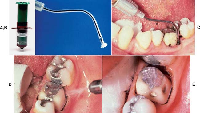
Fig. 14-7 Hemorrhage control with ferric sulfate with an infusor syringe. A and B, Ferric sulfate coagulative hemostatic gel and tip of infusor syringe. C, Ferric sulfate is released as the tip is moved back and forth in contact with the bleeding area. D, The area is cleaned with water spray. E, Once bleeding is controlled, cord is placed in the conventional manner before impression making.
(A and E, Courtesy Ultradent Products Inc., Salt Lake City, Utah.)
Displacement paste
Some dentists advocate displacement paste† (Fig. 14-8) as an alternative to cord.14 The product consists of an aluminum chloride-containing paste that is injected into the dried sulcus with a special delivery gun. Advantages of the system include good hemostasis with less discomfort than traditional cord. However, less tissue displacement is achieved than with cord, which may make die trimming more problematic. Improved displacement may be achieved if the paste is directed into the sulcus by applying pressure with a hollow cotton roll.‡
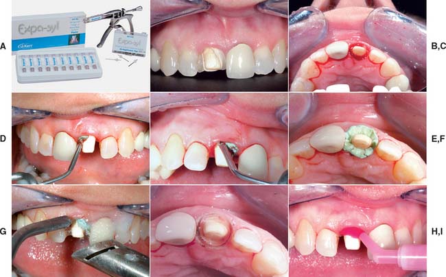
Fig. 14-8 A, Expa-syl is an aluminum chloride-containing paste used for gingival displacement. The material is dispensed from a syringe directly into the sulcus. B, Fractured ceramic crown had defective margins, which led to significant tissue inflammation and hemorrhage. C, Crown removed. D to F, Paste is directed into the gingival tissues around the prepared margin. G, After 1 to 2 minutes, the paste is removed with copious amounts of water. H, Prepared tooth before injecting impression material (I).
(A, Courtesy of Kerr Dentistry, Orange, California; B to I, Courtesy of Dr. Tony Soileau.)
Electrosurgery
An electrosurgery unit15—18 (Fig. 14-9A) may be used for minor tissue removal before impression making. In one technique,19 the inner epithelial lining of the gingival sulcus is removed, thus improving access for a subgingival crown margin (see Fig. 14-9B to F) and effectively controlling postsurgical hemorrhage20 (provided that the tissues are not inflamed). Unfortunately, there is the potential for gingival tissue recession after treatment.21
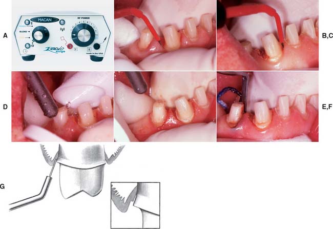
Fig. 14-9 A, An electrosurgery unit. B, The tip of the electrode is used to probe the area where the incisions will be made. C, The tip of the electrode is passed through the hyperplastic tissue. D, The area is irrigated and dried for inspection (E). F, After tissue removal, cord placement precedes impression making. G, Tissue should only be removed from the inner surface of the sulcus.
(A, Courtesy of Macan Engineering Co., Chicago, Illinois.)
An electrosurgery unit works by passage of a high-frequency current (1 to 4 million Hz*) through the tissue from a large electrode to a small one. At the small electrode, the current induces rapid localized polarity changes that cause cell breakdown (“cutting”). For restorative procedures, an unmodulated alternating current is recommended, because it minimizes damage to deeper tissues.16
The following facts should be considered before electrosurgery is attempted:
Soft tissue laser
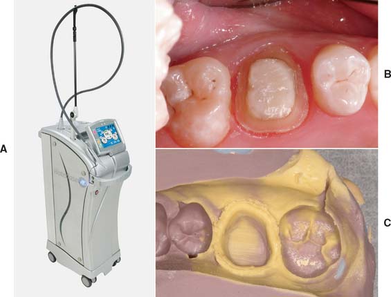
Soft tissue lasers (Fig. 14-10) have been advocated as a means of removing a controlled amount of tissue before impression making.24 They are also useful for tissue contouring procedures.
MATERIALS SCIENCE
Elastic Impression Materials
There is an extensive variety of materials for making a precision negative mold of soft and hard tissues. In order of their historical development, they are the following:
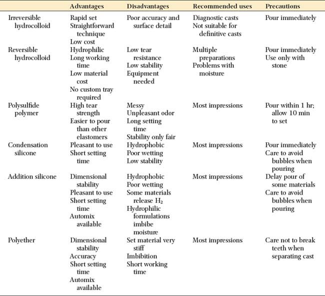
Irreversible hydrocolloid is not sufficiently accurate for cast restorations. Each material has advantages and disadvantages, and none is entirely free of shortcomings. However, they all share one important characteristic: when handled correctly, they can produce casts of sufficient accuracy25 and surface detail26 for the fabrication of clinically acceptable fixed prostheses.
Nevertheless, there are reasons for selecting one material over another: If it becomes necessary to store the impression before a cast is made, the polyethers and addition silicones are preferable because they exhibit sufficient long-term dimensional stability; the other materials, particularly the reversible hydrocolloids, must be poured immediately. If the impression is to be poured in epoxy or electroplated (see Chapter 17), reversible hydrocolloid should not be selected because it is compatible only with die stone.
The advantages and disadvantages of the elastic impression materials are summarized in Table 14-3.
Reversible hydrocolloid
Reversible hydrocolloid (also called agar hydrocolloid or simply hydrocolloid) (Fig. 14-11) was originally derived as a natural product of kelp. However, the material currently available is considerably different.
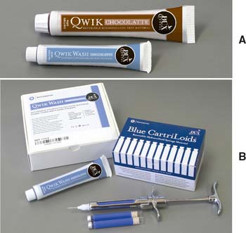
Fig. 14-11 Reversible hydrocolloid impression material. A, Tray and wash material. B, Syringe material.
(Courtesy of Dux Dental, Oxnard, California.)
If poured immediately, reversible hydrocolloid produces casts of excellent dimensional accuracy and acceptable surface detail. At elevated temperatures, it changes from a gel to a sol. This change is reversible; that is, as the material cools, the viscous fluid sol is converted to an elastic gel. Agar changes from gel to sol at 99°C (210°F) but remains a sol as low as 50°C (122°F), forming a gel only slightly above body temperature. These unique characteristics are very favorable for its use as an impression material.
Reversible hydrocolloid is supplied in a range of viscosities. In general, a heavy-bodied tray material is used with a less viscous syringe material. The required temperature changes are effected with a special conditioning unit (see Fig. 14-31) and water-cooled impression trays.
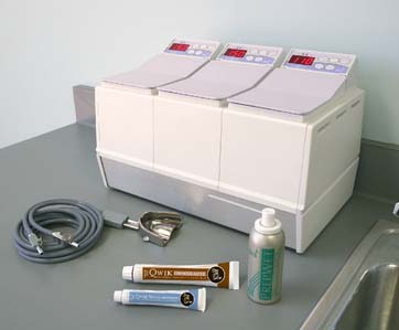
Fig. 14-31 Hydrocolloid conditioning equipment consists of three thermostatically controlled water baths: boiling, storage, and tempering.
(Courtesy of Dux Dental, Oxnard, California.)
Reversible hydrocolloid’s lack of dimensional stability results primarily from the ease with which water can be released from or absorbed by the material (syneresis and imbibition). The accuracy of a reversible hydrocolloid impression is improved if the material has as much bulk as possible (low surface area/volume ratio). This contrasts with the elastomeric impression materials, whose accuracy is improved by minimizing bulk (e.g., polysulfide and condensation silicone), because stresses produced during removal are reduced.27 Therefore, an additional advantage of reversible hydrocolloid is that a custom impression tray is not required.
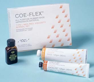
Polysulfide polymer
The polysulfides (Fig. 14-12), commonly (although erroneously) known as rubber bases,* were introduced in the early to middle 1950s. They were received enthusiastically by dentists because they had better dimensional stability and tear strength than did hydrocolloid. Nevertheless, they should be poured as soon as possible after impression making; delays of more than an hour result in clinically significant dimensional change.22
There is a slight contraction of polysulfide during polymerization, but the effects can be minimized with a custom impression tray to reduce the bulk of the material.28 In general, a double-mix technique is used with a heavy-bodied tray material and a less viscous syringe material. These polymerize simultaneously, forming a chemical bond of adequate strength.29
The high tear resistance30,31 and enhanced elastic properties of polysulfide facilitate impression making in sulcular areas and pinholes, and it has improved dimensional stability over hydrocolloid (inferior to polyether and addition silicone). Although it is the least expensive elastomer, it is not well liked by patients because of its unpleasant sulfide odor and long setting time in the mouth (about 10 minutes). Furthermore, high humidity and temperature dramatically reduce its working time,32 which may be so short that polymerization begins before it is inserted in the mouth, which results in severe distortion. Although air conditioning is common in dental operatories, temperatures near 25°C (77°F) with humidity exceeding 60% can create problems.
Most polysulfide materials are polymerized with the aid of lead peroxides, which explains this material’s typical brown color. The unpolymerized product is sticky and should be handled carefully, because it stains clothing permanently. Alternatives to lead are available; copper hydroxide is the most common. Cu(OH)2-polymerized polysulfide is light green and shares many of the characteristics of the PbO2-polymerized material (except for a reduced setting time).
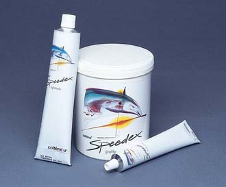
Condensation silicone
Some of polysulfide’s disadvantages have been overcome by condensation silicone (Fig. 14-13), which is essentially odorless and can be pigmented to virtually any shade. Unfortunately, its dimensional stability is less than that of polysulfide but greater than that of reversible hydrocolloid. An advantage of this silicone is its relatively short setting time in the mouth (about 6 to 8 minutes). As a result, patients tend to prefer condensation silicone over polysulfide. In addition, condensation silicone is also less affected by high operating room temperatures and humidity.27
Silicone’s main disadvantage is its poor wetting characteristics, which stems from its being extremely hydrophobic (for this reason, it is used in commercial sprays that protect automobile electrical systems from moisture). In this context, the prepared teeth and gingival sulci must be completely free of moisture so that a defect-free impression is possible. Pouring without trapping air bubbles is also more difficult than with other impression materials, and a surfactant may be needed. Silicone impression material is available in a variety of viscosities. One technique involves a heavily filled putty material that is used to customize a stock impression tray in the mouth, generally with a polyethylene spacer. The spacer allows room for a thin wash of light-bodied material, which makes the impression. The technique requires considerable care in seating, however, to prevent strain in the set putty. If this happens, the impression rebounds when removed from the mouth, which results in dies that are too small.33 Care is also needed to avoid contaminating the putty surface with saliva, which prevents the wash impression from adhering properly.34
Silicone and polysulfide have a dimensional instability that results from their mode of polymerization. Both are condensation polymers, which, as a byproduct of their polymerization reactions, give off alcohol and water, respectively. As a result, evaporation from the set material causes dimensional contraction in both.
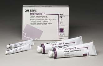
Polyether
Polyether impression material (Fig. 14-14), developed in Germany in the mid-1960s, has a polymerization mechanism unlike those of the other elastomers. No volatile byproduct is formed, which results in excellent dimensional stability. In addition, its polymerization shrinkage35 is unusually low in comparison with most room temperature—cured polymer systems. However, its thermal expansion36 is greater than that of polysulfide.
With the high dimensional stability of polyether, accurate casts can be produced when the material is poured more than a day after the impression has been made. This is especially useful when pouring the impression immediately is impossible or inconvenient. Another advantage of polyether is its short setting time in the mouth (about 5 minutes, which is less than half the time required for polysulfide). For these reasons, polyether is used by many practitioners.
However, polyether has certain disadvantages. The stiffness of the set material is one such disadvantage, which causes problems when a stone cast is separated from the impression. Thin and single teeth, in particular, are liable to break unless the practitioner uses great care. Polyether is stable only if stored dry, because it absorbs moisture and undergoes significant dimensional change. Polyether’s relatively short working time may limit the number of prepared teeth that can be reliably captured in a single impression. Isolated cases of allergic hypersensitivity37 to polyether elastomer have been reported (manifested as sudden onset of burning, itching, and general oral discomfort). Therefore, the allergic patient’s record should carry a warning against polyether’s future use, and an alternative elastomer should be chosen. Improvements in these materials have reportedly reduced this problem.
Addition silicone
Addition silicone (Fig. 14-15) was introduced as a dental impression material in the 1970s. Also known as poly(vinyl siloxane) (polysiloxane is the generic chemical expression for silicone resins), it is similar in many respects to condensation silicone except that it has much greater dimensional stability38 (equivalent to polyether polymer), and its working time is more affected by temperature.26 The set material is less rigid than polyether but stiffer than polysulfide. As with the other materials previously described, adverse soft-tissue responses have been reported.39 One disadvantage of some of these materials is that setting inhibition can occur with selected latex gloves.40 Dithiocarbamates, which are used in glove manufacturing as either vulcanizing agents or accelerators, have been implicated as causative agents.41 Glove exposure to alcohol has been shown to exacerbate setting inhibition for selected impression material—latex glove combinations.42 The problem is most apparent if a hand-mixed putty is used, but problems can occur if the tissues are touched with gloved hands immediately before impression placement. It has also been shown that sulfide and sulfide-chloride can be transferred from latex gloves to retraction cord,43 which enables the transfer of these known inhibiting agents to sulcular tissues (Fig. 14-16). When addition silicones are used, gloves that do not interfere with setting should be selected.44
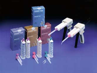
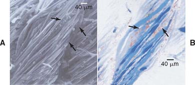
Fig. 14-16 A, Scanning electron microscope finding of gingival retraction cord contaminated by latex glove contact. Arrows indicate particles on surfaces and within fibers of gingival retraction cord. B, Electron probe microanalysis of gingival retraction cord contaminated by latex glove contact. Red color indicates sulfur element (arrows).
(From Kimoto K, et al: Indirect latex glove contamination and its inhibitory effect on vinyl polysiloxane polymerization. J Prosthet Dent 93:433, 2005.)
Like condensation silicone, addition silicones are hydrophobic. Some formulations contain surfactants, which give them hydrophilic properties,45 imparting wettability similar to that of the polyethers.46 However, these products also expand like polyether when in contact with moisture.47 Addition silicone is generally used as a two-viscosity system, although monophase formulations are also available. It is easier to trap bubbles when the monophase formulation is used.48
Manufacturer recommendations should be followed when a cast is being poured, and pouring should be delayed with some of the earlier products. If this is not done, a generalized porosity of the cast surface caused by gas from the impression material will develop. Newer products contain “scavengers” that prevent the escape of gas at the polymer-cast interface. Addition silicone that contains scavenger material can be poured immediately.
IMPRESSION TRAYS
The choice of impression material influences tray selection. Reversible hydrocolloids require special water-cooled trays, whereas irreversible hydrocolloid and many elastomeric impressions for uncomplicated fixed prosthodontic procedures are made with prefabricated impression trays. To reduce associated distortion invariably associated with the use of such trays, they must have adequate rigidity, and tray design should provide for control of impression material thickness. Retention is provided by perforations, rim locks, and/or adhesives (Fig. 14-17). Custom trays are fabricated for each patient individually, through the use of diagnostic casts (see Chapter 2), and offer a number of advantages over prefabricated stock trays.
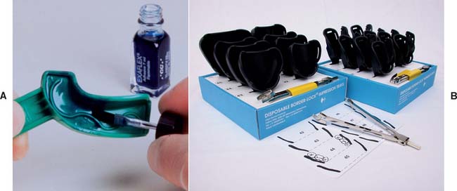
Fig. 14-17 A, This prefabricated segmented tray relies on internal modification to ensure material thickness. B, This system allows the dentist to match tray size to patient arch width.
(B, Courtesy of Clan Dental Products, Maarheeze, The Netherlands.)
Adhesives should be applied sufficiently in advance to allow thorough drying, although they may remain slightly tacky to touch. Because evaporation of its volatile solvent is time dependent, it is preferable to apply the adhesive in a thin layer. Spray-on adhesives have been shown to result in significantly less retention of polyvinylsiloxane impression materials to both autopolymerizing and photopolymerizing tray materials than do paint-on adhesives.49
CUSTOM TRAY FABRICATION
A custom tray improves the accuracy50 of an elastomeric impression by limiting the volume of the material, thus reducing two sources of error: stresses during removal and thermal contraction. Although reducing the bulk of an elastomeric impression material increases its accuracy, the opposite is true for reversible hydrocolloid impressions. In hydrocolloid impressions, dimensional change is caused by water loss (or gain) from the surface of the impression. A bulky hydrocolloid impression has a lower surface area/volume ratio and is therefore less subject to dimensional change.
Custom trays can be made from autopolymerizing acrylic resin (Fig. 14-18), thermoplastic resin, or photopolymerized resins. Thermoplastic materials can be softened in a water bath and adapted either manually or with a vacuum former with a heating element (Figs. 14-19 and 14-20). The accuracy of impressions made with a thermoplastic tray material or light-polymerized materials is comparable with that of impressions made with an autopolymerized resin.51,52 Light-polymerized materials are convenient because a storage period is not needed for the completion of polymerization53 (Fig. 14-21). In addition, the resin is less susceptible to distortion in moisture, and the impression is thus suitable for the electroformed die technique (see Chapter 17). With the appropriate adhesive, it produces a better bond to the impression material.54
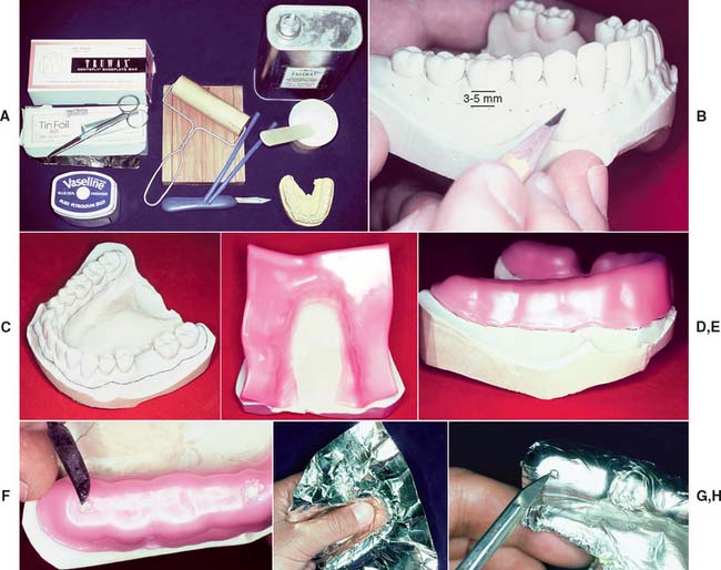
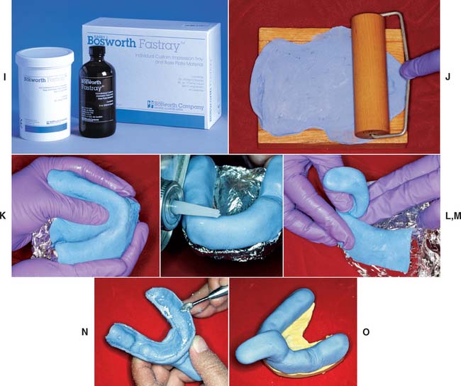
Fig. 14-18 Custom tray fabrication. A, Armamentarium. B, Outlining the border of the tray on the diagnostic cast. C, The tray should extend 3 to 5 mm from the gingival margin and about 3 mm beyond the most distal tooth. D, Softened baseplate wax is adapted to form a spacer. Two thicknesses typically provide the recommended 2 to 3 mm of space. E, Spacer is trimmed to the pencil line. F, Wax is removed to form the tray stops. G, The impression is covered with tinfoil. H, The foil is adapted to the stops. I, Custom tray resin. J, Wooden slab and roller are used. K, The resin is gently adapted to the cast, and the excess is trimmed. L and M, Resin is moistened with monomer to attach the handle. N, When the resin has cured, the periphery is shaped with an acrylic-trimming bur. O, Trimmed custom tray.
(I, Courtesy of Harry J. Bosworth Company, Skokie, Illinois.)
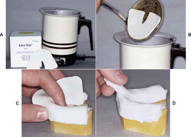
Fig. 14-19 Thermoplastic custom tray material. A and B, The material is softened in hot water. C and D, The material has been adapted to the spaced cast.

Fig. 14-20 Vacuum-formed custom tray material. A, The thermoplastic sheets are much thicker and more rigid than those used for making interim restorations (see Chapter 15), but the same equipment is used (B).
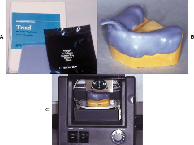
Fig. 14-21 Visible light-polymerized custom tray material. A and B, The material is removed from the packet and adapted to the spaced cast. C, The assembly is placed on the turntable of a special curing unit and exposed to intense light.
With any system, tray rigidity is important, because even slight flexing of the tray leads to a distorted impression. This is particularly frustrating because the errors are usually undetectable until the practitioner attempts to seat the restoration. For this reason, thin, disposable plastic trays are unacceptable.55 Resin thicknesses of 2 to 3 mm are needed for adequate rigidity. Clearance between the tray and the teeth should also be 2 to 3 mm; however, greater clearance is necessary for the more rigid polyether materials.
Armamentarium (see Fig. 14-18A)
Step-by-Step Procedure: Autopolymerizing Resin
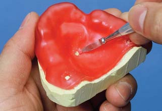
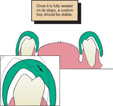
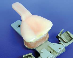
Fig. 14-23 Drawing of a cross-section through a mandibular custom tray. Stops have been placed on the nonfunctional cusps so that distortion does not interfere with the intercuspal relationship. The 45-degree slope helps to center the tray during seating (arrow). Space exists for the impression material.
Step-by-Step Procedure: Photopolymerized Resin
Follow steps 1—5 as for the autopolymerizing technique.
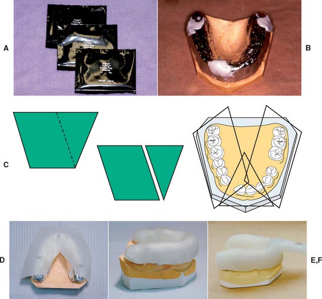
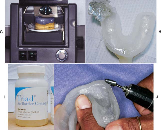
Fig. 14-25 Custom tray fabrication with photopolymerized resin. A, Material is supplied in light-proof packaging. B, Small pieces of resin are applied in the areas of the stops first, to make sure they get filled completely. C, Sheets should be cut as shown. D, Material is adapted to the cast, the large piece of material first. E, The material is adapted until the pieces blend together and no seams are visible. F, A handle is formed by molding excess material. G, The resin is cured for approximately 2 minutes. H, The softened wax spacer and aluminum barrier are removed. I, An air-barrier coating is used to prevent a sticky oxygen-inhibited layer. J, Trimming the tray.
(A to J, Courtesy Dr. R. Seghi.)
Evaluation
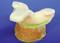
The completed custom tray (Fig. 14-18O) needs to be rigid, with a consistent thickness of 2 to 3 mm. It should extend about 3 to 5 mm cervical to the gingival margins and should be shaped to allow muscle attachments. It should be stable on the cast with stops that can maintain an impression thickness of 2 or 3 mm. The tray must be smooth, with no sharp edges. Finally, the handle should be sturdy and shaped to fit between the patient’s lips (Fig. 14-26).
To avoid distortion from continued polymerization of the resin,56 the tray should be made at least 9 hours before its use. When a tray is needed more urgently, it can be placed in boiling water for 5 minutes and allowed to cool to room temperature. A light-polymerized tray can also be made (see Fig. 14-25).
IMPRESSION MAKING
Elastomeric Materials
When elastomeric impressions are made, an assistant is essential, unless the AutoMix technique is used.
Step-by-step procedure
Heavy body—light body combination
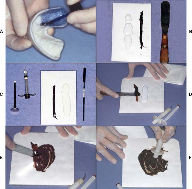
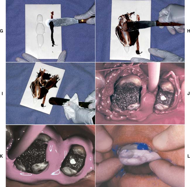
Fig. 14-27 Elastomeric impression-making (polysulfide polymer). A, Adhesive applied to the tray. Sufficient time is allowed for drying. B, Heavy-bodied tray material. C, Light-bodied syringe material. D, The brown catalyst is picked up first. E, The light-bodied (white) material is thoroughly spatulated. F, Impression syringe being loaded. G and H, Meanwhile, an assistant mixes the heavy-bodied material. I, The spatula is wiped to prevent unmixed material from being incorporated into the impression. J and K, Displacement cord is removed, and the impression material is applied by syringe into the sulcus, around the prepared teeth, and into the grooves of the occlusal surfaces. The material is air-blown into a thin layer at this time. L, The impression tray is filled with heavy-bodied material and seated.
When mixing polysulfide polymers, pick up the brown catalyst first (Fig. 14-27D) rather than the white base material, because the base sticks to the spatula and makes it virtually impossible to incorporate all the catalyst.
Concurrently with steps 5 through 9, have the assistant mix the heavy-bodied material in a similar manner as the light-bodied material (Fig. 14-27G to I) and load the tray.
Single-mix technique
The same steps are performed for the single-mix technique as for the heavy body—light body technique; however, as the name indicates, only one mix is used to load the syringe and fill the tray. Most single-mix materials tend to produce a slightly higher viscosity mix with a slightly shorter working time.
AutoMix technique
Most manufacturers offer impression material in prepackaged cartridges with a disposable mixing tip attached (Fig. 14-28). The cartridge is inserted in a caulking gun-like device, and the base and catalyst are extruded into the mixing tip, in which mixing occurs as they progress to the end of the tube. The homogeneously incorporated material can be directly placed on the prepared tooth and impression tray. One of this system’s advantages is the elimination of hand mixing on pads; the elimination of this variable has been shown to produce fewer voids in the impression.58 Following the manufacturer’s directions and bleeding the cartridge before inserting the tip are crucial to ensure that possible residue of partially polymerized material is removed from the cartridge openings, which might prevent equal amounts of base and catalyst from being dispensed. AutoMix material is not available for the polysulfide polymers because these materials are too sticky for proper mixing with existing cartridge tips.
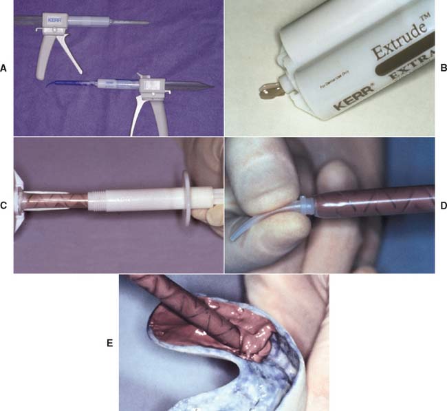
Fig. 14-28 A, AutoMix addition silicone impression materials are available in a range of viscosities. B, The barrels should be bled to ensure that any partially set material is removed and that the flow is even from each component. To prevent cross-contamination of the catalyst and base, a mixing tip should remain attached to the cartridge after each use. C, The light-bodied material can be dispensed into an impression syringe or directly onto the prepared tooth with a special tip (D). The heavy-bodied material is dispensed into the adhesive-coated tray (E).
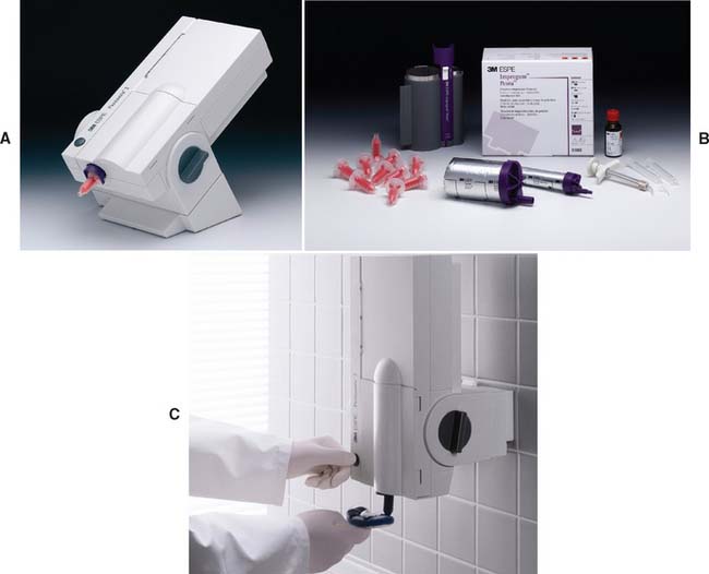
Machine mixing technique
An alternative method for improving impression mixing is to use a machine mixer* (Fig. 14-29). This system is convenient and produces void-free impressions.
Evaluation
The impression must be inspected for accuracy when it is removed (Fig. 14-30). (Magnification is helpful.) If bubbles or voids appear in the margin, the impression must be discarded. An intact, uninterrupted cuff of impression material should be present beyond every margin. Streaks of base or catalyst material indicate improper mixing and may render an impression useless. If the impression passes all these tests, it can then be disinfected (see p. 460) and poured to obtain a die and definitive cast (see Chapter 17).
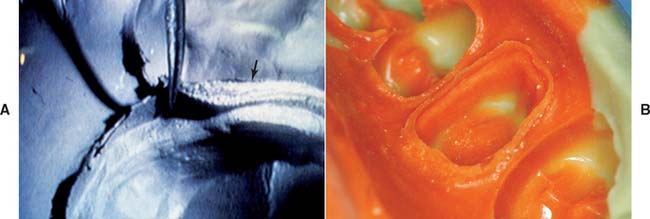
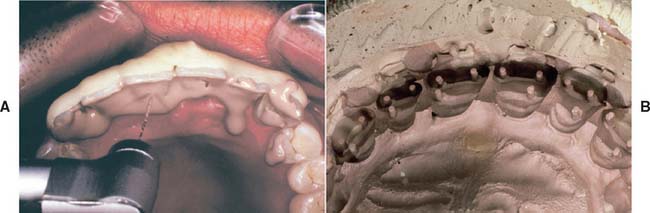
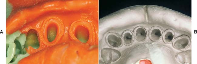
Fig. 14-30 Impression evaluation. A, Low magnification of elastomeric impression. On the left an adequate cuff is formed by material extending beyond the preparation margin. On the right side (arrow) the impression does not extend adequately. B, This impression reproduces an adequate amount of the unprepared tooth structure cervical to the preparation margin.
Reversible Hydrocolloid
Reversible hydrocolloid impression material requires a special conditioning unit (Fig. 14-31), which is made up of three thermostatically controlled water baths:
Step-by-step procedure
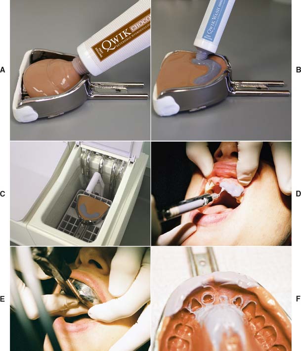
Fig. 14-32 Hydrocolloid impression technique. A, The water-cooled impression tray is loaded with heavy-bodied material. B, The wash hydrocolloid is squeezed onto the tray material in the area of the preparations. C, The filled tray is placed in a tempering bath for the recommended 3 minutes. The entire arch is flooded with water or a surfactant. D, Alternatively, some dentists prefer a syringe technique. E, Water-cooling tubes are connected and then the tray is seated. F, The completed impression. Light-bodied material should have been displaced by the tray material.
(Courtesy of Dux Dental, Oxnard, California.)
Evaluation
A reversible hydrocolloid impression is evaluated in the same manner as polysulfide polymer (Fig. 14-32F). However, the translucency of the material may make small imperfections difficult to detect. If doubt exists, it may be expedient to make a new impression, because this does not require additional tissue displacement and can be easily accomplished.
Closed-Mouth Impression Technique
The closed-mouth impression technique, also called the dual-arch or triple tray technique, is popular for making impressions for single units and less expensive restorations made to conform to the existing occlusion.59,60 The impression is made at maximum intercuspation with a high-viscosity polyether or polyvinylsiloxane impression material supported by a thin mesh in a frame. The impression includes the prepared tooth, the adjacent teeth, and the opposing teeth and records their maximum intercuspation relationship (hence the name “triple tray”). Because the impression is made at the occlusal vertical dimension, the technique facilitates making a highly accurate impression61 and occlusal record. However, the laboratory stages must be performed very carefully and, as no eccentric relationships are recorded, these need to be evaluated and adjusted at restoration delivery.
Step-by-step procedure (Fig. 14-33)
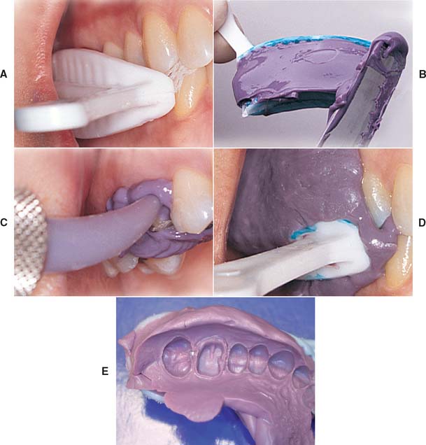
Fig. 14-33 Closed-mouth impression technique. A, The tray is selected and evaluated. B, Loaded tray. C, Impression material delivered by syringe. D, Patient closes into maximum intercuspation. E, Completed impression.
(A to D, Courtesy of Premier Dental Products Co., Plymouth Meeting, Pennsylvania.)
Evaluation
The impression is evaluated for accuracy and detail (see Fig. 14-33E). Ensure that the patient has not closed into the sides or distal bar of the tray.
Special Considerations
Certain modifications of the basic impression technique are sometimes needed, particularly for making impressions with additional retention features such as pinholes and post space.
Pin-retained restorations
Elastomeric impression materials are strong enough to reproduce a pinhole without tearing. However, to avoid bubbles, they must be introduced carefully into the pinhole with a lentulo or cement tube (Fig. 14-34). With reversible hydrocolloid, a special nylon bristle must be used for the impression.
Step-by-step procedure
Lentulo
Prefabricated plastic pin
Post and cores
Elastomeric materials can be successfully used to make impressions of the post space when endodontically treated teeth are being restored. The procedure involves reinforcing the impression with a plastic pin or suitable wire (e.g., orthodontic wire), as described in Chapter 12.
Disinfection
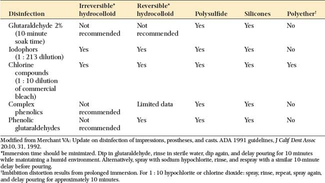
When they are removed from the patient’s mouth, it must be assumed that all impression materials have been in contact with body fluids. They should be disinfected according to the recommended procedures for the material being used. After being removed from the patient’s mouth, the impression is immediately rinsed with tap water and dried with an air syringe. Suitable chemicals should be used, such as glutaraldehyde solutions or iodophor sprays. Table 14-4 shows the most commonly recommended techniques for the materials discussed in this section. Some are perfectly acceptable for one material but unsuitable for others. Because of its tendency to distort and absorb moisture, polyether or “hydrophilic” addition silicone impression materials should be sprayed and stored in a plastic bag rather than submerged and soaked in a glutaraldehyde solution. Disinfection is an essential step for preventing cross-infection and exposure of laboratory personnel. If it is performed properly, disinfection does not affect the accuracy or surface reproduction of the elastomer.62,63
Evaluation
After disinfection, the completed impression (Fig. 14-35) is inspected carefully before the definitive cast is made. An elastomeric impression should be dried before it is evaluated. The following points are then considered:
SUMMARY
An impression or negative likeness of the teeth and surrounding structures is used to obtain a cast, on which the planned restoration is fabricated. A good impression is an exact negative replica of each prepared tooth and must include all of the prepared surfaces and an adequate amount of unprepared tooth structure adjacent to the margin.
Healthy soft tissues and the control of saliva flow are essential for a successful impression. However, caution must be exercised to prevent injury to the gingiva. Cotton rolls, cards, and saliva evacuators are needed for adequate moisture control. Use of a local anesthetic to minimize discomfort and to reduce saliva flow during the impression procedure is recommended.
Mechanical, chemical, and surgical methods for enlargement of the gingival sulcus can be used to obtain access to subgingival margins of prepared teeth. However, a narrow cord impregnated with a mild astringent (e.g., AlCl3) is recommended. To protect the smear layer, excessive contact between hemostatic agents and cut tooth structure should be avoided.
A custom acrylic resin tray should be used when making an impression with any of the elastomeric materials. All impression materials should be rinsed, dried, and disinfected when removed from the mouth. Impressions made with polysulfide polymer should be poured within 1 hour. Impressions made with polyether or addition silicone have high dimensional stability and can be stored considerably longer before pouring. When making pin-retained restorations, a cement tube, lentulo, or nylon bristle is needed for an accurate impression of the pinholes or post spaces. In this technique and others, a good impression is crucial for an accurately fitting restoration.
 GLOSSARY*
ac·cel·er·a·tor \ăk-s l′a-rā′ter\ n (1611): 1: a substance that speeds a chemical reaction 2: in physiology, a nerve, muscle, or substance that quickens movement or response
agar \ā′gar′, ä′gar′\ n (1889): a complex sulfated polymer of galactose units, extracted from Gelidium cartilagineum, Gracilaria confervoides, and related red algae. It is a mucilaginous substance that melts at approximately 100° C and solidifies into a gel at approximately 40° C. It is not digested by most bacteria and is used as a gel in dental impression materials and a solid culture media for microorganisms.
an·es·the·sia \ăn′ s-thē′zha\ n (ca. 1721): loss of feeling or sensation; also spelled anaesthesia
au·to·poly·mer \ô′tō-p l′a-mer\ n: a material that polymerizes by chemical reaction without external heat as a result of the addition of an activator and a catalyst—au·to·poly·mer·i·za·tion \ô′tō-pl′a-mr-zā′shun\ vb
cat·a·lyst \kăt′l-st\ n (1902): a substance that accelerates a chemical reaction without affecting the properties of the materials involved
cau·tery \kô′te-rē\ n, pl -ter·ies (15c): the application of a caustic substance, hot instrument, electric current, or other agent used to burn, scar, or destroy tissue
colloid \kl′oid\: a material in which is suspended a constituent in a finely divided state that is invisible to the eye but capable of scattering light
custom tray \kŭs′tum trā\: an individualized impression tray made from a cast recovered from a preliminary impression. It is used in making a final impression
dimensional stability \d-mn′shun-l sta-bl′-tē\: the ability of a material to retain its size and form
e·las·to·mer \-lăs′ta-mer\ n (ca. 1934): a polymer whose glass transition temperature is below its service temperature (usually room temperature). These materials are characterized by low stiffness and extremely large elastic strains—e·las·to·mer·ic adj
final impression \fī′nal m-prsh′on\: the impression that represents the completion of the registration of the surface or object
functionally generated path \fŭngk′sha-na-lē jn′a-rāt′d păth\: a registration of the paths of movement of the occlusal surfaces of teeth or occlusion rims of one dental arch in plastic or other media attached to the teeth or occlusal rims of the opposing arch
gingival displacement \jn′ja-val ds-plās′ment\: the deflection of the marginal gingiva away from a tooth
hydrocolloid \hī′dra-kl′oid\ n (1916): a colloid system in which water is the dispersion medium; those materials described as a colloid sol with water that are used in dentistry as elastic impression materials—see IRREVERSIBLE H., REVERSIBLE H.
hyperplastic tissue \hī′per-plăs′tik tsh′ōō\: excessive tissue proliferation, usually as a response to chronic irritation
hy·per·tro·phy \hī-pûr′tra-fē\ n (1834): an enlargement or overgrowth of an organ or tissue beyond that considered normal as a result of an increase in the size of its constituent cells and in the absence of tumor formation
im·pres·sion \m-prsh′an\ n (14c): a negative likeness or copy in reverse of the surface of an object; an imprint of the teeth and adjacent structures for use in dentistry—see ALTERED CAST PARTIAL DENTURE I., DENTAL I., DIRECT BONE I., AREA, I. MATERIAL I., TRAY I., MASTER I., PARTIAL DENTURE I., PRELIMINARY I., SECTIONAL I., TUBE I.
impression material \m-prsh′an mă-tîr′ē-al\: any substance or combination of substances used for making an impression or negative reproduction
impression technique \m-prsh′an tk′nēk\ obs: a method and manner used in making a negative likeness (GPT-4)
impression tray \m-orsh′an trā\: 1: a receptacle into which suitable impression material is placed to make a negative likeness 2: a device that is used to carry, confine, and control impression material while making an impression
is·chem·ia \-skē′mē-a\ n (ca. 1860): local and temporary deficiency of blood, chiefly resulting from the contraction of a blood vessel
master impression \măs′tar m-prsh′an\: the negative likeness made for the purpose of fabricating a prosthesis
mon·o·mer \mn′a-mar\ n (1914): a chemical compound that can undergo polymerization; any molecule that can be bound to a similar molecule to form a polymer
ne·cro·sis \na-krō′ss, n-\ n, pl ne·cro·ses \sēz\ (1665): localized death of living tissue
poly·eth·er \pl′ē-ē′thar\ adj: an elastomeric impression material of ethylene oxide and tetra-hydrofluro copolymers that polymerizes under the influence of an aromatic ester
poly·sul·fide \pl′ē-sŭl′fīd\ n (1849): an elastomeric impression material of polysulfide polymer (mercaptan) that cross-links under the influence of oxidizing agents such as lead peroxide
poly(vinyl siloxane) \pl′ē-vī′nal sī-lks′ān\ n: an addition reaction silicone elastomeric impression material of silicone polymers having terminal vinyl groups that cross-link with silanes on activation by a platinum or palladium salt catalyst.
reversible hydrocolloid \r-vûr′sa-bal hī′dra-kl′oid′\: colloidal gels in which the gelation is brought about by cooling and can be returned to the sol condition when the temperature is sufficiently increased
spat·u·la \spăch′a-la\ n (1525): a flat-bladed instrument used for mixing or spreading materials
surface tension \sûr′fas tn′shun\: a property of liquids in which the exposed surface tends to contract to the smallest possible area, as in the spherical formation of drops. This is a phenomenon attributed to the attractive forces, or cohesion, between the molecules of the liquid.
tissue displaceability \tsh′ōō ds-plās′a-bl′-tē\: 1: the quality of oral tissues that permits them to be placed in other than a relaxed position 2: the degree to which tissues permit displacement
tissue displacement \tsh′ōō ds-plās′mant\: the change in the form or position of tissues as a result of pressure. Frequently used to describe gingival tissue placement prior to impression making.
tissue reaction \tsh′ōō rē-ăk′shun\: the response of tissues to an altered condition
vinyl polysiloxane \vī′năl pa-lē′s-lk′sān\ n: an addition reaction silicone elastomeric impression material of silicone polymers having terminal vinyl groups that cross-link with silanes on activation by a platinum or palladium salt catalyst. Called also vinyl(polysiloxane)
STUDY QUESTIONS
1 McCormick JT, et al. Wettability of elastomeric impression materials: effect of selected surfactants. Int J Prosthod. 1989;2:413.
2 Kissov HK, Chalashkanova MI. The impression as a means for analysis of clinical mistakes in fixed prosthodontics. Folia Med (Plovdiv). 2001;43(1—2):84.
3 Council on Dental Therapeutics, American Dental Association. Accepted Dental Therapeutics, 38th ed., Chicago: American Dental Association; 1979:247.
4 Sherman CR, Sherman BR. Atropine sulfate: a current review of a useful agent for controlling salivation during dental procedures. Gen Dent. 1999;47:56.
5 Findlay D, Lawrence JR. An alternative method of assessing changes in salivary flow: comparison of the effects of clonidine and tiamenidine (HOE 440). Eur J Clin Pharmacol. 1978;14:231.
6 Wilson EL, et al. Effects of methantheline bromide and clonidine hydrochloride on salivary secretion. J Prosthet Dent. 1984;52:663.
7 Laufer BZ, et al. The closure of the gingival crevice following gingival retraction for impression making. J Oral Rehabil. 1997;24:629.
8 Bowles WH, et al. Evaluation of new gingival retraction agents. J Dent Res. 1991;70:1447.
9 Land MF, et al. Disturbance of the dentinal smear layer by acidic hemostatic agents. J Prosthet Dent. 1994;72:4.
10 Land MF, et al. Smear layer instability caused by hemostatic agents. J Prosthet Dent. 1996;76:477.
11 Pelzner RB, et al. Human blood pressure and pulse rate response to racemic epinephrine retraction cord. J Prosthet Dent. 1978;39:287.
12 Jokstad A. Clinical trial of gingival retraction cords. J Prosthet Dent. 1999;81:258.
13 Hansen PA, et al. Current methods of finish-line exposure by practicing prosthodontists. J Prosthodont. 1999;8:163.
14 Cranham JC. Predictable impressioning. Dent Equip Mater. May/June 2003:46.
15 Harris HS. Electrosurgery in Dental Practice. Philadelphia: JB Lippincott, 1976.
16 Gnanasekhar JD, al-Duwairi YS. Electrosurgery in dentistry. Quintessence Int. 1998;29:649.
17 Louca C, Davies B. Electrosurgery in restorative dentistry. I. Theory. Dent Update. 1992;19:319.
18 Louca C, Davies B. Electrosurgery in restorative dentistry. II. Clinical applications. Dent Update. 1992;19:364.
19 Podshadley AG, Lundeen HC. Electrosurgical procedures in crown and bridge restorations. J Am Dent Assoc. 1968;77:1321.
20 Maness WL, et al. Histologic evaluation of electrosurgery with varying frequency and waveform. J Prosthet Dent. 1978;40:304.
21 DeVitre R, et al. Biometric comparison of bur and electrosurgical retraction methods. J Prosthet Dent. 1985;53:179.
22 Walter C. Dental treatment of patients with cardiac pacemaker implants. Quintessence Int. 1975;8:57.
23 Krejci RF, et al. Effects of electrosurgery on dog pulps under cervical metallic restorations. Oral Surg. 1982;54:575.
24 Parker S. The use of lasers in fixed prosthodontics. Dent Clin North Am. 2004;48:971.
25 Tjan AH, et al. Clinically oriented evaluation of the accuracy of commonly used impression materials. J Prosthet Dent. 1986;56:4.
26 Setz J, et al. Profilometric studies on the surface reproduction of dental impression materials. Dtsch Zahnarztl Z. 1989;44:587.
27 Luebke RJ, et al. The effect of delayed and second pours on elastomeric impression material accuracy. J Prosthet Dent. 1979;41:517.
28 Eames WB, et al. Elastomeric impression materials: effect of bulk on accuracy. J Prosthet Dent. 1979;41:304.
29 Cullen DR, Sandrik JL. Tensile strength of elastomeric impression materials, adhesive and cohesive bonding. J Prosthet Dent. 1989;62:142.
30 Herfort TW, et al. Tear strength of elastomeric impression materials. J Prosthet Dent. 1978;39:59.
31 Hondrum SO. Tear and energy properties of three impression materials. Int J Prosthodont. 1994;7:517.
32 Harcourt JK. A review of modern impression materials. Aust Dent J. 1978;23:178.
33 Fusayama T, et al. Accuracy of the laminated single impression technique with silicone materials. J Prosthet Dent. 1974;32:270.
34 Tjan AH. Effect of contaminants on the adhesion of light-bodied silicones to putty silicones in putty-wash impression technique. J Prosthet Dent. 1988;59:562.
35 Henry PJ, Harnist DJR. Dimensional stability and accuracy of rubber impression materials. Aust Dent J. 1974;19:162.
36 Mansfield MA, Wilson HJ. Elastomeric impression materials: a method of measuring dimensional stability. Br Dent J. 1975;139:267.
37 Nally FF, Storrs J. Hypersensitivity to a dental impression material: a case report. Br Dent J. 1973;134:244.
38 Lacy AM, et al. Time-dependent accuracy of elastomer impression materials. II. Polyether, polysulfides, and polyvinylsiloxane. J Prosthet Dent. 1981;45:329.
39 Sivers JE, Johnson GK. Adverse soft tissue response to impression procedures: report of a case. J Am Dent Assoc. 1988;116:58.
40 Peregrina A, et al. Effect of two types of latex gloves and surfactants on polymerization inhibition of three polyvinylsiloxane impression materials. J Prosthet Dent. 2003;90:289.
41 Tseng KC, et al: Effect of dithiocarbamate on polymerization of polyvinylsiloxane impression materials [Abstract 1645]. Presented at American Association of Dental Research/International Association of Dental Research Annual Session, Baltimore, March 9—12, 2005.
42 Peregrina A, et al. Effect of two types of latex gloves and surfactants on polymerization inhibition of three polyvinylsiloxane impression materials. J Prosthet Dent. 2003;90:289.
43 Kimoto K, et al. Indirect latex glove contamination and its inhibitory effect on vinyl polysiloxane polymerization. J Prosthet Dent. 2005;93:433.
44 Matis BA, et al. The effect of the use of dental gloves on mixing vinyl polysiloxane putties. J Prosthodont. 1997;6:189.
45 Boening KW, et al. Clinical significance of surface activation of silicone impression materials. J Dent. 1998;26:447.
46 Pratten DH, Craig RG. Wettability of a hydrophilic addition silicone impression material. J Prosthet Dent. 1989;61:197.
47 Oda Y, et al. Evaluation of dimensional stability of elastomeric impression materials during disinfection. Bull Tokyo Dent Coll. 1995;36:1.
48 Millar BJ, et al. In vitro study of the number of surface defects in monophase and two-phase addition silicone impressions. J Prosthet Dent. 1998;80:32.
49 Peregrina A, et al. The effect of different adhesives on vinyl polysiloxane bond strength to two tray materials. J Prosthet Dent. 2005;94:209.
50 Millstein P, et al. Determining the accuracy of stock and custom tray impression/casts. J Oral Rehabil. 1998;25:645.
51 Gordon GE, et al. The effect of tray selection on the accuracy of elastomeric impression materials. J Prosthet Dent. 1990;63:12.
52 Martinez LJ, von Fraunhofer JA. The effects of custom tray material on the accuracy of master casts. J Prosthodont. 1998;7:106.
53 Wirz J, et al. Light-polymerized materials for custom impression trays. Int J Prosthod. 1990;3:64.
54 Bindra B, Heath JR. Adhesion of elastomeric impression materials to trays. J Oral Rehabil. 1997;24:63.
55 Burton JF, et al. The effects of disposable and custom-made impression trays on the accuracy of impressions. J Dent. 1989;17:121.
56 Pagniano RP, et al. Linear dimensional change of acrylic resins used in the fabrication of custom trays. J Prosthet Dent. 1982;47:279.
57 McCabe JF, Carrick TE. Rheological properties of elastomers during setting. J Dent Res. 1989;68:1218.
58 Chong YH, et al. The effect of mixing method on void formation in elastomeric impression materials. Int J Prosthod. 1989;2:323.
59 Wilson EG, Werrin SR. Double arch impressions for simplified restorative dentistry. J Prosthet Dent. 1983;49:198.
60 Donovan TE, Chee WWL. A review of contemporary impression materials and techniques. Dent Clin North Am. 2004;48:445.
61 Ceyhan JA, et al. The effect of tray selection, viscosity of impression material, and sequence of pour on the accuracy of dies made from dual-arch impressions. J Prosthet Dent. 2003;90:143.
62 Drennon DG, et al. The accuracy and efficacy of disinfection by spray atomization on elastomeric impressions. J Prosthet Dent. 1989;62:468.
63 Drennon DG, Johnson GH. The effect of immersion disinfection of elastomeric impressions on the surface detail reproduction of improved gypsum casts. J Prosthet Dent. 1990;63:233.