17 DEFINITIVE CASTS AND DIES
Because direct fabrication of patterns for extracoronal restorations in the mouth is inconvenient, difficult, time consuming, and virtually impossible, practically all wax patterns are made in the laboratory with the indirect technique. This technique requires an accurate reproduction of the prepared tooth, the surrounding soft tissues, and the adjacent and opposing teeth. A cast-and-die system captures the necessary information so that it can be transferred to the laboratory.
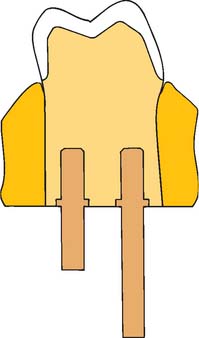
The definitive cast (or master or working cast) is the replica of the prepared teeth, ridge areas, and other parts of the dental arch. The die is the positive reproduction of the prepared tooth and consists of a suitable hard substance of sufficient accuracy (usually an improved stone, resin, or metal) (Fig. 17-1).
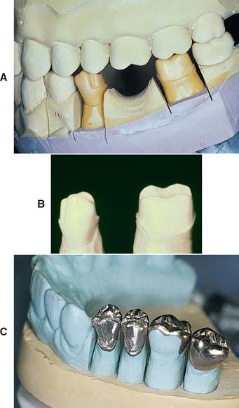
Fig. 17-1 Removable die system. A, Definitive cast. B, The individual dies. C, Epoxy die.
(C, Courtesy of Dr. J. H. Bailey.)
The accuracy of a cast and die is a function of the completeness and accuracy of the impression. The cast cannot contain more information than the impression from which it was made.
This chapter describes the requirements of a cast-and-die system and correlates these with the available materials. The procedures are generally straightforward, but the steps must be followed carefully if the intended prosthesis is to be successful.
PREREQUISITES
The cast that will be used to make the fixed restoration must meet certain requirements. It must reproduce all details captured in the impression and should be free of defects. Depending on their location, however, minor imperfections may be acceptable (Fig. 17-2). The cast must meet certain requirements:
MATERIALS SCIENCE
Gypsum
The two crucial characteristics of cast-and-die materials, dimensional accuracy and resistance to abrasion while the wax pattern is being formed, are adequately achieved with gypsum. This material is inexpensive, is easy to use, and produces consistent results. Manufactured in enormous quantities for industrial use, it can easily be modified for dental use.
Dental gypsum products are available in five forms (American Dental Association [ADA] types I to V), defined as impression plaster; model plaster; dental stone; high-strength dental stone; and high-strength, high-expansion stone. The gypsum components are identical chemically. The setting reaction results from the hydration of calcium sulfate hemihydrate:
CaSO4 • ½H2O + 1½H2O → CaSO4 • 2H2O
The hemihydrate is manufactured by heating the dihydrate under controlled conditions to drive off some of the water of crystallization (a process called calcination). The differences between the various types of dental gypsum are attributable to calcination. The physical properties of die stone are improved over those of dental stone and plaster because less water is needed to obtain a sufficiently fluid mix.*
Hand mixing of gypsum products is easy, but results are better when the mixing is done mechanically in a vacuum. Porosity is reduced, with a concomitant increase in strength, after only 15 seconds of mechanical mixing. Newly poured casts should be left undisturbed for at least 30 minutes; superior results are achieved at 1 hour, although these times may vary among brands.
Surface detail reproduction is acceptable with type IV and type V gypsum products. The materials are capable of reproducing a 20-μm-wide line as prescribed by ADA specification No. 19.1 However, not all brands of die stone are compatible with all brands of impression material,2,3 and if poor surface detail reproduction is experienced, an alternative product should be selected.
With some techniques (e.g., when a cast is prepared for duplication), it is necessary to soak the set gypsum in water. However, although it appears to be insoluble, the gypsum slowly dissolves, which ruins the surface detail of the cast. If soaking is required, it should be done in water saturated with plaster slurry and only long enough to achieve the desired degree of wetting.
Gypsum’s greatest disadvantage is its relatively poor resistance to abrasion. Attempts to overcome this have included the use of so-called “gypsum hardeners.” Although these materials (e.g., colloidal silica) have relatively little effect on the hardness of the stone, they improve abrasion resistance (some by as much as 100%).4 Their use is accompanied by a slight increase in setting expansion, but such is probably not clinically significant. An alternative approach5 is to impregnate the surface of the die with a low-viscosity resin such as cyanoacrylate. As mentioned earlier, abrasion resistance is the physical property most improved by this technique. Care is needed when the resin is selected and applied so that the resin film will have no significant thickness.6 Experts continue their efforts to improve the properties of die stone. One approach is to apply additives used in industrial applications (e.g., concrete manufacture) to dental gypsum products.7 Another is the use of a gum arabic, calcium hydroxide mixture.8 Resin-strengthened gypsum products such as ResinRock,* with high strength and low expansion,9 are also popular and are particularly suitable for casts for implant restorations (see Chapter 13).
Additional, even stronger die materials are also available. These include resin and electroplated dies.
Resin
Resins are used as a die material to overcome the low strength and abrasion resistance of die stone. Most available resin die materials are epoxy resins, but polyurethane is also used. Epoxy resin is well known as a household and industrial adhesive. It can be cured at room temperature without expensive or complicated equipment, and it yields a form that is reasonably stable dimensionally. Its abrasion resistance is many times greater than that of gypsum products. However, it is more expensive than gypsum, and it undergoes some shrinkage during polymerization.
Epoxy resins suitable for fabrication of precision dies are available, although there is a great deal of variability among brands.10 The amount of shrinkage upon polymerization is quantitatively about equal to the expansion with gypsum. Polymerization shrinkage is less of a problem with newer formulations11 and polyurethane resin.12 When used with poly (vinyl siloxane), contemporary resin systems produce complete arch casts with similar dimensional accuracy to traditional die stone.13 In general, detail reproduction is better14; however, prostheses fabricated on resin dies tend to fit more tightly than those made on gypsum.15
Certain impression materials (i.e., polysulfide and hydrocolloid) are not compatible with resin. However, good results are achieved with silicone and polyether.
Electroplated Dies
Besides resin, electroplating can be used to overcome the poor abrasion resistance of gypsum. This technique16 has been in use for many years and involves the deposition of a coat of pure silver or copper on the impression. The areas to be plated are first coated with finely powdered silver or graphite to make them conduct electricity, and the impression is then placed in an electroplating bath. A layer of pure metal is deposited on the impression and is supported with type IV stone or resin.
Although electroplating has been in use for some time, several problems remain. Variable degrees of distortion commonly occur, and the technique must be performed slowly; otherwise, distortions in the metal subsequently stress the impression. The time necessary to produce a cohesive film of metal (typically 8 hours) is ample for the development of dimensional changes in the impression. However, when made properly, an electroplated die can be as accurate as a stone die,17,18 although not all impression materials are suitable for plating. Because of their low surface energies, silicone impression materials are difficult to electroplate evenly. Some brands, however, are easier to plate than others.19 Polyether impressions, because of their hydrophilic nature, imbibe water and become distorted; they therefore cannot be plated accurately. Polysulfide polymers can be silver plated, but it is much more difficult to copper plate them. The main drawback of silver plating is the use of a cyanide solution, which requires special precautions because of its extreme toxicity.
Flexible Die Materials
Flexible die materials are similar to heavy-bodied silicone or polyether impression materials (see Chapter 14) and have been used to make interim restorations20,21 or indirect composite resin inlays or onlays22,23 chairside. The advantages of the flexible material over a stone die include more rapid setting and the ease of removal of the interim restoration or inlay. When choosing materials for flexible dies, the dentist must be sure to select a compatible combination of impression and die materials that provides good surface details. One study24 revealed that the best detail reproduction was obtained when Impregum F die material* was combined with Extrude Light impression material.†
SELECTION CRITERIA
Choosing one cast-and-die system over another depends on several factors:
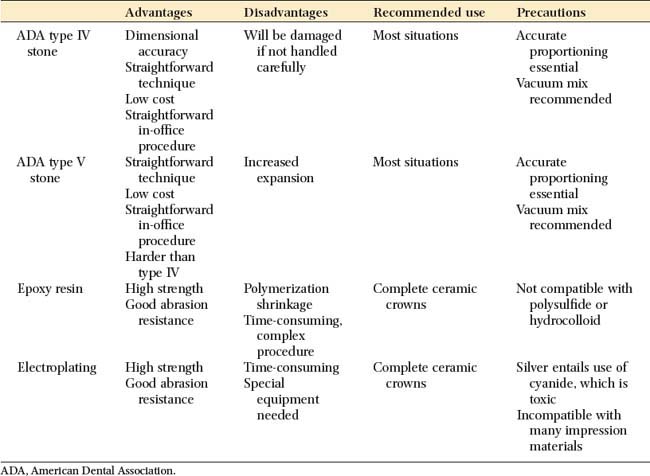
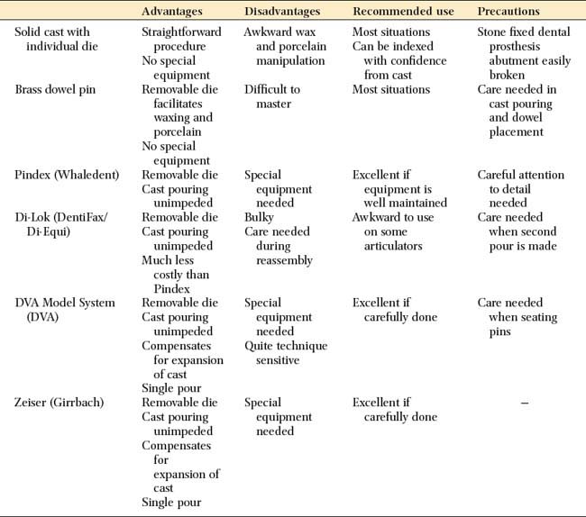
The advantages and disadvantages of the available materials are summarized in Table 17-1.
Available Methods
Removable dies
In a removable die system (see Fig. 17-1), the die is an integral component of the definitive cast and can be lifted from the cast to facilitate access. Precise relocation of the die in the definitive cast is crucial to this system’s success and is usually accomplished with brass pins or dowels (Fig. 17-5). When a single dowel is used, it should have at least one flat surface to provide resistance against rotation. Alternative methods (e.g., the popular Pindex* system [Fig. 17-6]), use multiple or interlocking dowels to ensure such resistance.
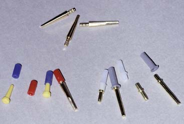
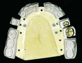
Fig. 17-6 Removable dies made with the Pindex (Whaledent) dowel system (see Fig. 17-21).
(Courtesy of Coltène/Whaledent AG, Altstatten, Switzerland.)
The cast is made in two pours of type IV or V stone† of contrasting colors: the first forms the teeth, and the second forms the base of the cast. The area to be removed is coated with a separating agent before the second layer is poured. In other areas, undercuts are provided to prevent unwanted separation. The location and orientation of the dowels are critical; if they are improperly placed, the dowels do not allow the die of the prepared teeth to be withdrawn from the cast (Fig. 17-7).
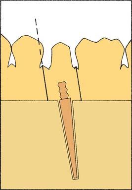
Fig. 17-7 Incorrect alignment of the dowel pin prevents removal of the die. The proximal surface of the adjacent tooth blocks die removal (dotted line).
In normal situations, dowels are positioned in the stone before it is set. However, drilling the cast and cementing the pins into the set stone are also possible.25
The Pindex system is designed to facilitate this latter technique. All removable die systems depend on careful execution so that the die will separate cleanly and return to place accurately. In one study, investigators found similar accuracy with four removable die systems, although the Pindex system showed the least horizontal movement, and the brass dowel pins produced the least occlusogingival reseating discrepancy.26
Solid cast with individual die
The solid cast-and–individual die system, also referred to as the multiple-pour technique, has certain advantages over the removable die system; its primary advantage is its simplicity. It may also be slightly more accurate.27 When the impression is judged to be satisfactory, it is poured in type IV or V stone in the area of the preparation or preparations only. When set, it is separated. A second pour is then made of the entire arch. (Sometimes the second pour is used for an additional set of individual dies for polishing, and the solid cast is obtained from a third pour.)
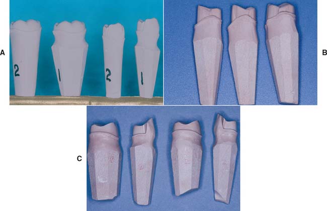
The first pour, which is the most accurate, is trimmed into a die with a handle of sufficient length (similar to a tooth root [Fig. 17-8]). The complete arch cast (second pour) is mounted on an articulator. The wax pattern is started on the initial pour (the die) and is then transferred to the articulated cast for refinement of axial contours and occlusal anatomy (see Chapter 18). When completed, this pattern is returned to the die so that the margins can be readapted immediately before investing.
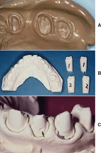
Fig. 17-8 A, An accurate impression is essential for successful fixed prostheses. B, The first and second pours have been sectioned into individual dies. The third pour will be the definitive cast. C, Small defects (arrow) can sometimes be overcome, but any voids make the laboratory phase much more difficult.
An advantage of the solid cast–individual die system is that the definitive cast requires only minimum trimming. Because the gingival tissues around the prepared teeth are left intact, they can be used as a guide when contouring the restorations. Disadvantages of the solid cast technique include the following:
Alternative die systems
The Di-Lok* technique (Fig. 17-9) involves the use of a specially articulated tray for precise reassembly of a sectioned definitive cast. The impression is poured, and the cast is trimmed into a horseshoe configuration that fits in the special tray. The tray is filled with a second mix, and the cast is seated. When the stone has set, the tray is disassembled, saw cuts are made on each side of the preparation, and the resulting die is trimmed. The cast and die can be reassembled in the tray, which is then mounted on an articulator. A disadvantage of this system is that the overall size of the tray can make articulation and manipulation awkward and difficult.
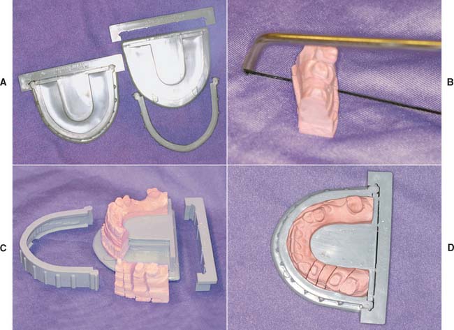
Fig. 17-9 The Di-Lok system. A, The system involves the use of specially segmented trays. With a single-pour technique, the impression is formed in the usual way, and the Di-Lok tray is filled. Then the tray is inserted into the impression while the stone is still wet. After the die stone has fully set, the locking and curved arms of the tray are removed. The cast can then be removed by tapping the anterior pad of the tray base. B, The dies are sectioned by sawing three-fourths through the stone and are separated by breaking the remaining stone base. C, Trimmed dies. D, Assembled cast ready for articulating.
(Courtesy of DentiFax/Di-Equi, Buffalo, New York.)
The DVA Model System* (Fig. 17-10) and the Zeiser model system† (Fig. 17-11) use a precision drill and special baseplates that are aligned and drilled to provide die removal. These systems offer the advantage of allowing for the expansion of stone, which is relieved by the saw cuts.
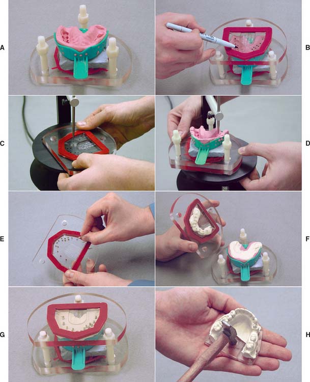
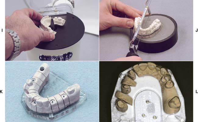
Fig. 17-10 DVA Model System. A, Trimmed impression on alignment fixture. B, Marking dowel pin locations on clear plate. C, Drilling holes for dowel pins as marked. D, Alternatively, the holes can be drilled with the top/base plate positioned on the underside of the fixture base. The pointer identifies the pin location. E, Inserting dowels in the baseplate. An adhesive is not required. F, The impression is poured and stone is placed around the dowel pins. G, The alignment fixture is replaced over poured impression. H, Set cast is removed from the baseplate with gentle tapping.
I, The cast is trimmed. J, Cast is sectioned. K and L, Definitive casts trimmed with the DVA Model System.
(A to K, Courtesy of Dental Ventures of America, Inc., Corona, California; L, courtesy of Dr. A. G. Wee.)
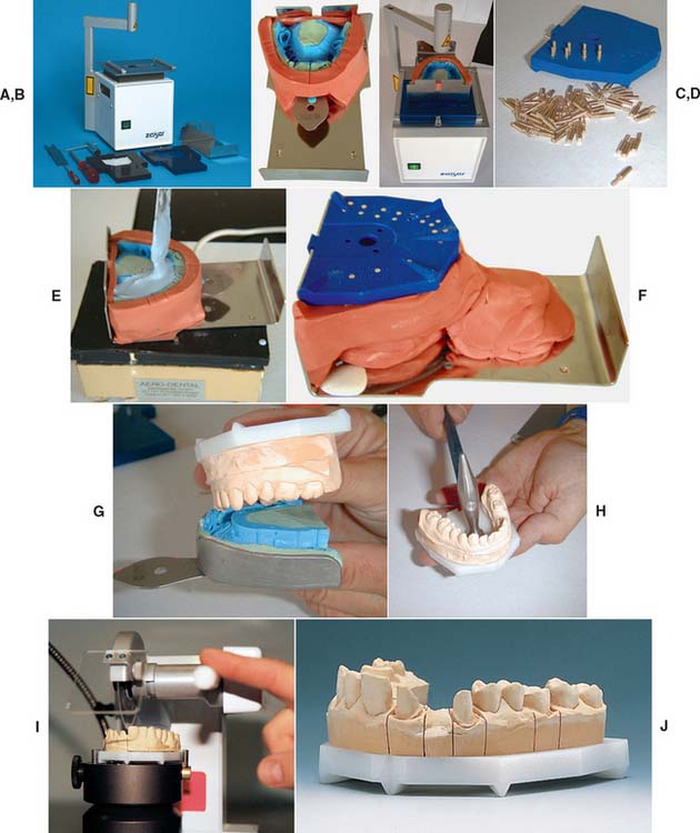
Fig. 17-11 A, Zeiser model system. B, The impression is leveled, blocked out with silcone putty, and positioned over the baseplate. C, The pin locations are determined and the pinholes drilled in the base. D, Pins are inserted into the base. The impression is poured (E) and the base inverted into the stone (F). G and H, The cast is separated from the impression when set and then separated from the base. I, A precision saw aids sectioning. J, The sectioned cast.
(Courtesy of Amann Girrbach GmbH, Koblach, Austria.)
Choice of Definitive Cast-and-Die System
The choice of a specific technique relies on operator preference and an assessment of each method’s advantages and disadvantages. If they are used properly, all the available systems achieve clinically acceptable accuracy.28 When establishing a new relationship with a dental technician, it is important to determine which cast-and-die systems are preferred and why the technician has chosen them. Close cooperation between the dentist and technician is a key factor in fixed prosthodontics.
The solid cast technique simplifies cast-and-die fabrication, but it makes the waxing and porcelain stages more difficult. However, there is no need for special equipment, and the soft tissues immediately adjacent to the preparation are not removed (which facilitates contouring the gingival areas of the restorations). The use of a solid definitive cast precludes errors caused by incomplete seating of a removable die. In practice, this means that the components of a fixed dental prosthesis (FDP) can be indexed from the cast for soldering; on the other hand, it also means that if an FDP is not accurately fabricated, the stone abutment teeth can be easily broken off, which makes subsequent steps more difficult.
The first pour from an elastomeric impression is the most accurate, and it is essential to readapt the margins of the wax pattern on the first-pour die immediately before the pattern is invested.
A dowel-and–removable die system’s main advantage is that it requires less manipulation of the wax pattern, which thus reduces the chances of breakage during transfer. In addition, the handling of porcelain restorations is easier, particularly if a porcelain labial margin is used. For these reasons, most technicians believe that the extra steps involved in making a cast with dowels and a removable die are worthwhile.
Nevertheless, the procedures are technically quite difficult. It is not rare to encounter dies that do not seat properly or that have poorly placed dowels. Difficulty also may be encountered in sawing the die out of the cast. Interproximal margins can easily be damaged during this procedure, particularly if clearance between a proximal preparation margin and the adjacent tooth is minimal.
In the Pindex system, a special drilling unit is used to ensure accurate pin placement. Careful model trimming of the initially poured cast is necessary before the holes for the pins are drilled. If the trimming is done properly, highly accurate and stable removable dies result; however, the cost of the additional equipment must be considered.
The advantages and disadvantages of these cast-and-die systems are summarized in Table 17-2.
TECHNIQUE
The techniques for pouring stone dies are similar for most of the popular systems. To avoid repetition, the procedure involving single dowel pins is described in detail, with an emphasis on the differences between the solid cast (multiple-pour) system and the Pindex system.
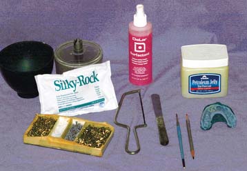
Armamentarium (Fig. 17-12)
After the impression has been removed from the patient’s mouth, it is washed under running tap water, blown dry, inspected, and disinfected (see Chapter 14). When it is judged to be satisfactory, it is taken to the laboratory, where the necessary armamentarium should have been prepared for use before impression making. A vacuum mixer (e.g., the Vac-U-Spat*) is strongly recommended. At this time the impression can be sprayed with a surfactant or, in the case of hydrocolloid, placed in a K2SO4 solution (if recommended by the manufacturer).
Step-by-Step Procedure
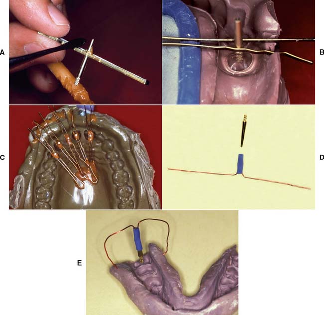
Fig. 17-13 Positioning dowel pins before cast pouring can be accomplished with bobby pins and sticky wax (A to C) or with prefabricated wire-tube aid (D and E).
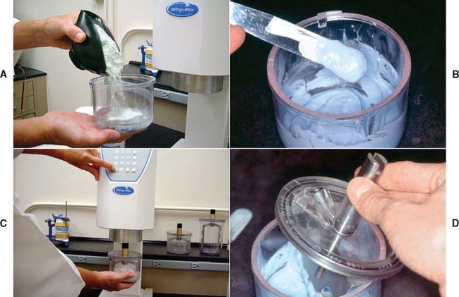
Fig. 17-14 Vacuum mixing type IV stone. A, The mixing bowl is rinsed and excess water shaken out. Measured distilled water is poured into the bowl, and weighed powder is added, or premeasured envelopes are used. The powder/liquid ratio should be according to the manufacturer’s recommended proportions. B, The mixture is spatulated by hand for approximately 60 seconds or until all powder is incorporated. C, The mixture is then mechanically spatulated under vacuum for an additional 20 to 30 seconds. D, The vacuum is broken slowly, excess mixture is removed from paddles, and the impression is poured.
(Courtesy of Whip Mix Corporation, Louisville, Kentucky.)
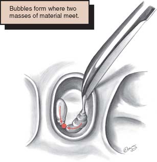
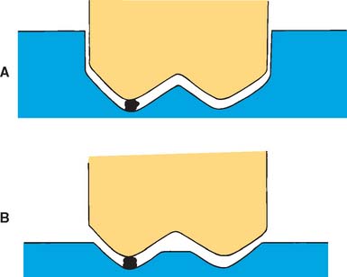
Fig. 17-15 Incorrect technique for pouring an impression. An air bubble (arrows) is trapped if two masses of stone are allowed to meet.
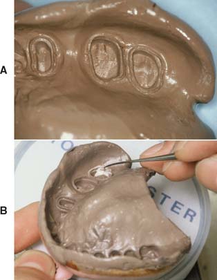
Fig. 17-16 Pouring an impression. A and B, To avoid trapping air, start with a very small amount of stone.
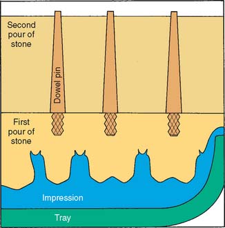
Fig. 17-17 Dowel pins must be carefully positioned so the first pour of stone completely covers the knurled head; otherwise, the parts do not separate cleanly. However, the stone should not extend onto the shaft and reduce stability.
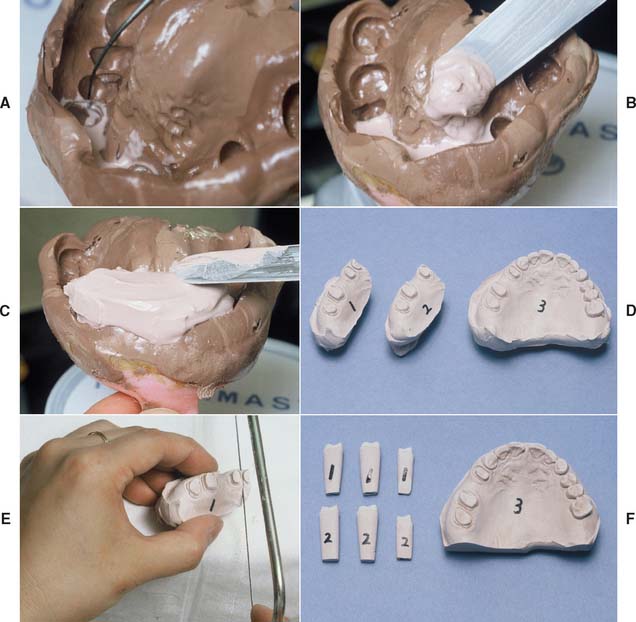
Fig. 17-18 Pouring an impression for individual dies and solid cast (multiple-pour system). A, Be sure that the critical margin area is covered. B, Stone added in the preparation area only. C, Sufficient bulk for the die handles. D, Pours 1 and 2 (individual dies) and 3 (definitive cast). E, Sectioning the individual dies. F, The trimmed dies and definitive cast before articulation.
Solid Cast-Multiple Pour System
For individual die pours, the stone mass must be built up to a height of approximately 25 mm to obtain a die handle of adequate length. The occlusal surfaces of teeth immediately adjacent to the preparation will be filled with stone, but this is of no concern (see Fig. 17-18). When the first pour has set, the cast is separated and repoured. The first pour is then sectioned into individual dies.
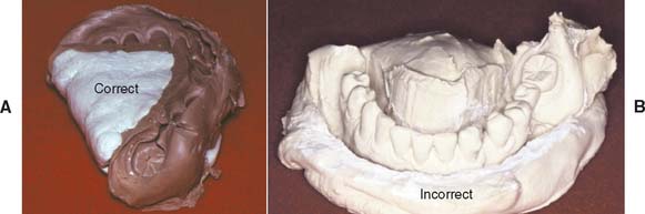
Fig. 17-20 A, Use a molding material to block out the lingual aspect before pouring a mandibular impression. B, Otherwise, excess stone will have to be ground away to obtain access to the lingual surfaces, which is a tedious process.
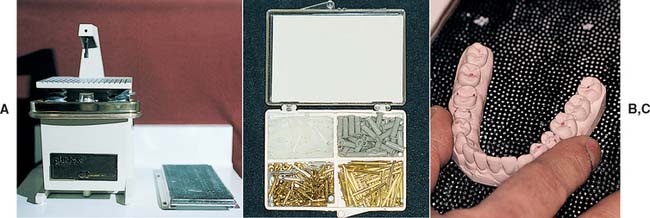
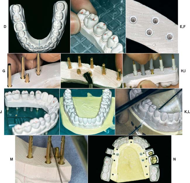
Fig. 17-21 The Pindex system consists of a special drill press (A) and brass dowels and plastic sleeves (B). C, The impression is poured in stone, separated when set, and trimmed to a horseshoe shape. The base must be absolutely flat (a trimmer is provided).
D, The location of each dowel is marked on the occlusal surface. Two dowels are needed to stabilize each segment. (Alternative single pins are available for small preparations.) E, The cast is positioned on the drill stage; a light indicates the location of the drill. The cast is held firmly and the lever depressed; this activates the drill, which penetrates into the cast. F, Each hole should be cleanly drilled; a hand reamer is available if necessary. G, The pins are tried in and cemented in place. For accessibility, the short locating dowels should be used on the lingual surface. H, The assembly is coated with petrolatum to ensure clean separation. I, The plastic sleeves are positioned. J, The assembly is placed in the special mold. K, The second pour of stone is made into the mold. After some stone has been painted between the pins, the first pour is placed into this mix. L, Sawing the dies. M, With the Pindex system, it is sometimes helpful to remove the first pour, use it as a block, and commence sawing from the base. Marking all the saw cuts with a pencil is recommended. N, The Pindex cast after sectioning.
(A to M, Courtesy of Dr. J.O. Bailey; N, Courtesy of Coltène/Whaledent AG, Altstatten, Switzerland.)
Pindex* System
When the Pindex system is being used, the first pour of stone is removed from the impression once it has set. The base is then ground flat in a plane that must be perpendicular to the intended position of the Pindex pins. The periphery of the cast is trimmed to fit in a special mold. After the cast is dried, the location of the pins is marked, and their holes are drilled with a special drill press. The pins are cemented in place with cyanoacrylate resin, special sleeves are positioned over the cemented pins, and the cast is positioned in the second pour that is made in the mold (see Fig. 17-21).
Sawing between adjacent prepared teeth is difficult, particularly with small anterior teeth. If this procedure is not performed carefully, the saw cuts can contact the dowel pin, leading to an unusable die. When the Pindex system is used, it is advantageous to remove the part of the first pour that contains the adjacent prepared teeth in one piece before making the critical saw cuts. Then the cuts can be carefully marked and started from the base and the tooth side (see Fig. 17-21M). When sawing from the base, it is important to protect the fragile dies with a soft cloth.
* Coltène/Whaledent, Inc., Cuyahoga Falls, Ohio.
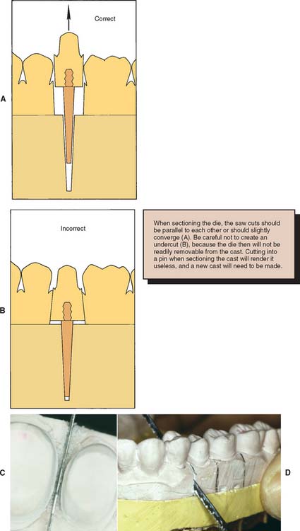
Fig. 17-22 Sectioning removable dies. A, The saw cuts should converge slightly toward the dowel; otherwise, the die will be locked in by undercuts (B). C, Mark the intended saw cuts in pencil and carefully position the saw blade. It must not touch the prepared tooth. D, Saw completely through the first pour. Finishing the cut short of the second pour will prevent a clean separation.
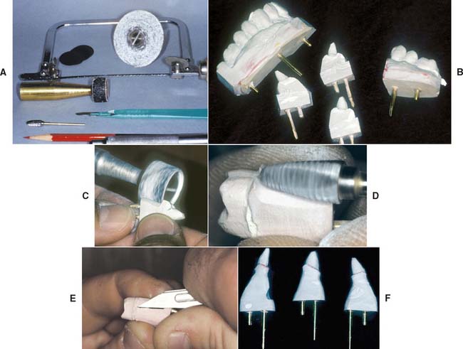
Fig. 17-23 Trimming dies. A, Armamentarium. B, Sectioned dies. In this instance, the Pindex system has been used. C, Bulk trimming is accomplished with an Arbor band on a lathe equipped with efficient dust collection. D, An acrylic-trimming bur is used near the margin. E, A sharp scalpel is used to trim to final contour, working away from the margin. F, The trimmed dies.
(B, C, and F, Courtesy of Dr. W. V. Campagni.)
All excess stone, with the exception of the critical few millimeters immediately adjacent and cervical to the margin, should be removed with an Arbor band or another cutter in a lathe. The stone that is closer to the margin is removed with a large carbide bur. (Easy access to the margin is mandatory for waxing.) Any residual flash is trimmed away with a sharp scalpel. The margin must not be touched. A binocular microscope is helpful during this step. It is important not to create a ditch apical to the margin, which could lead to poor gingival contour in the completed restoration (Fig. 17-24).
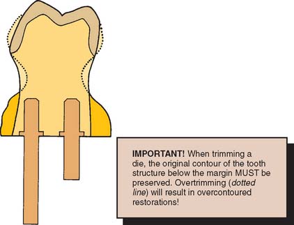
Fig. 17-24 Excessive trimming leads to a bulky crown, because the trimmed die acts as a guide to gingival contour when the restoration is being waxed.
When die trimming is completed, the dies are repositioned in the definitive cast, and their accurate and precise repositioning is verified. The definitive cast is then mounted on an articulator. Trimmed dies must be handled carefully. To minimize potential breakage, they should be secured in a container lined with foam plastic, gauze, or cotton.
MOUNTING CASTS ON AN ARTICULATOR
The articulation of diagnostic casts is discussed in Chapter 2. The technique for mounting a solid definitive (master) cast is identical. The procedure for attaching a definitive cast with removable dies to an articulator differs only in that access must be allowed to the area of the base into which the dowels penetrate. This expedites removal of the dowels (Fig. 17-25).
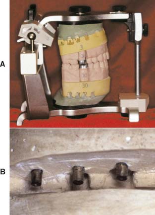
Fig. 17-25 A, Definitive cast attached to an articulator. B, To facilitate removal, the mounting should allow access to the end of each dowel. This is achieved by adding wax or weather stripping to the tips of the pins.
Definitive Casts versus Diagnostic Casts
The accuracy of the casts and their mounting is even more crucial for definitive casts than for diagnostic casts. Although diagnostic casts can still provide the necessary information even when mounted slightly inaccurately, definitive casts must be precisely mounted if lengthy chairside adjustment is to be avoided.
Diagnostic casts are most effectively mounted with a centric relation (CR) record (see Chapter 2). This allows the practitioner to visualize the full range of mandibular movement for occlusal diagnosis. The CR record is made at an increased vertical dimension (see Chapter 2). Closing the articulator upon removal of the record induces error if an arbitrary facebow is used.34 There is a slight error even if a kinematic facebow is used.35 Although such errors are probably not clinically significant with diagnostic casts, they are significant when definitive casts are involved, because the degree of inaccuracy is transferred to restorations fabricated and adjusted on the casts. Whenever possible, definitive casts should be mounted with a record made at the occlusal vertical dimension, by using maximum intercuspation (MI) of unprepared teeth.36 If this is not possible, a kinematic facebow recording is recommended. Problems associated with mounting casts with a CR record by using an arbitrary facebow were analyzed by Weinberg.37 He calculated that a 3-mm thick record can create an occlusal discrepancy in the first molar region of 0.2 mm when the arbitrary axis differs from the true hinge axis by 5 mm (a common error).
In addition, an elastomeric (rather than an irreversible hydrocolloid) impression should be made for the opposing cast. The elastomer’s improved precision results in a more accurate opposing cast, which reduces the need to adjust the restoration at evaluation.
Reorganized Occlusion
The decision to reorganize a patient’s occlusion (e.g., by making CR coincide with MI) is made at the treatment-planning stage (see Chapter 3). Treat-ment steps may then include occlusal adjustment of the existing dentition by selective reshaping (see Chapter 6) and reorganization of the anterior (incisal) guidance before tooth preparation for definitive cast restorations.
The following question should be asked during treatment planning: Is there any discernible pathologic process that may have arisen from malocclusion? In the presence of wear facets, widened periodontal ligament spaces, and muscle tenderness, the potential benefits of occlusal adjustment should be weighed. Another question must also be asked: Will reorganization of the occlusion benefit the patient? If the answer is yes, occlusal adjustment can be performed (see Chapter 6), after which definitive tooth preparation for fixed prosthodontics should be initiated.
The definitive casts can then be related at the occlusal vertical dimension with one of several techniques. Autopolymerizing resin may be used to record the relationship (Fig. 17-26). Alter-native materials include impression plaster, zinc oxide–eugenol impression paste on a suitable carrier (e.g., autopolymerizing acrylic resin or gauze), and some of the stiffer elastomers (polyether or poly[vinyl siloxane]).
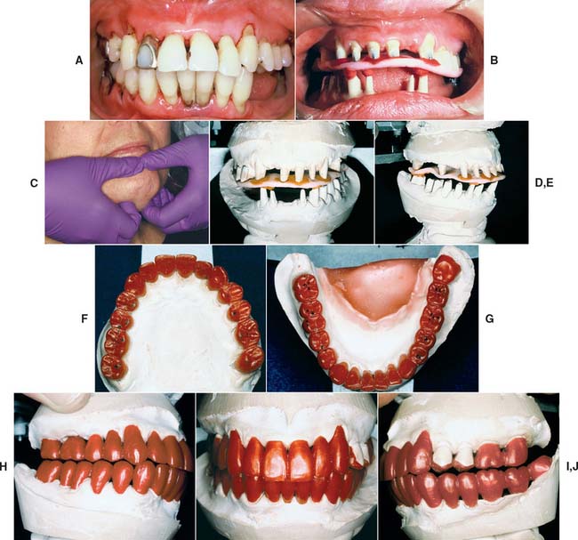
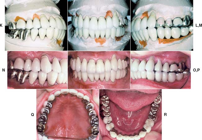
Fig. 17-26 Mounting definitive casts on the articulator. A, When a dentition requires extensive fixed prosthodontic care, accuracy of the articulation is essential for successful treatment. B, Recording centric relation at the occlusal vertical dimension minimizes the error inherent in a facebow transfer. Autopolymerizing acrylic resin was used as the recording medium. C, Manipulation of the mandible into centric relation. D and E, Definitive casts articulated with the CR record interposed. F to J, Restorations waxed to anatomic contour, with anterior guidance. K to M, Metal-ceramic restorations on the definitive cast. N to R, The completed restorations (see Fig. 32-44).
These records are optimal if they include only the cusp tips (Fig. 17-27). If more detail of the grooves is inadvertently captured, it should be carefully trimmed away. Otherwise, the cast will not seat properly and the restoration will be in supraclusion.
Conformative Occlusion
On many occasions, a cast restoration that conforms to the patient’s existing occlusion is made, even if a discrepancy exists between CR and MI positions. Typically, if no significant signs of clinical pathology processes are detected, fabricating simple prostheses in the stable MI position is acceptable. The objective is to maintain rather than reorganize a healthy masticatory apparatus.
When a patient has a symptom-free occlusion and requires relatively few cast restorations (i.e., when only a small part of the dentition needs to be restored), the MI position is the most desirable treatment. Therefore, in many patients who need only one or two single crowns (or a small FDP), the best restorations conform with their existing occlusion.
Articulating a definitive cast for a restoration that is to be waxed conformatively poses certain problems. If the cast is mounted with a CR record (as described for diagnostic casts in Chapter 2), the MI position is not reproduced accurately enough for precise waxing because it is in a translated mandibular position. This position cannot be reached with absolute precision on a semiadjustable articulator. In addition, during closing of the instrument, the stone cast can be easily damaged.
Probably the most practical solution is to articulate the definitive cast in maximum intercuspation by using a small interocclusal record (e.g., with poly[vinyl siloxane]) interposed between the tooth preparation and the opposing arch in the closed position (Fig. 17-28). At evaluation, after the restoration has been fabricated, the patient’s CR closure is examined clinically to ascertain that the restoration conforms to the preexisting occlusion. No premature contacts should occur on the new restoration. In CR closure, new occlusal interferences can be introduced on the restoration, and the discrepancy between CR and MI may be effectively increased, which leads to new problems (Fig. 17-29). It is then necessary to adjust the restoration to allow the original closing movement of the patient and to provide a smooth transition from the CR to the MI position.
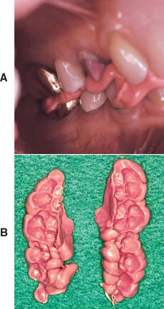
Fig. 17-28 A, Conformative interocclusal record made with poly(vinyl siloxane) polymer. B, The records before trimming.
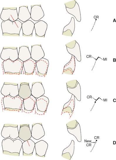
Fig. 17-29 When providing a restoration that conforms to an existing occlusion, it is important to assess both centric relation (CR) and maximum intercuspation (MI) carefully. A, Before treatment, the CR contact in this patient was on the first molar (arrows). B, Preoperative MI. C, The new restoration conforms to MI satisfactorily, but notice that a new CR interference (D, arrow) has been created.
Verification of Mounting
It is essential to check the accuracy of the articulation before proceeding with the laboratory phase of treatment. For less complex fixed prosthodontics, this can be accomplished simply by comparing the occlusal contacts in the patient’s mouth with those made by the casts. (Mylar shim stock or articulating film is suitable.) Occlusal wax (see Chapter 6) is also useful. For more extensive procedures, a second occlusal record is needed that can be compared with the first by using a split-cast mounting technique (Fig. 17-30) or a system such as the Denar Vericheck* (see Fig. 2-26).
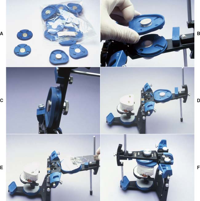
Fig. 17-30 A, Magna-Split system mounting procedure. B and C, In this system, indexed magnetic plastic mounting plates are used to facilitate split-cast mounting. D to F, The system used to attach the maxillary cast. The second record is confirmed if the indices align precisely.
(Courtesy of Panadent Corporation, Grand Terrace, California.)
TECHNIQUE FOR CLOSED-MOUTH IMPRESSIONS
The closed-mouth impression technique, also called the dual-arch or triple-tray technique, is popular for making impressions for single units and limited restorations made to conform to the existing occlusion38,39 (see Chapter 14). The importance of the laboratory stages cannot be overstressed. The procedure is different depending on the articulator used. This description is for the V2 Quadrant Articulator (Fig. 17-31).†
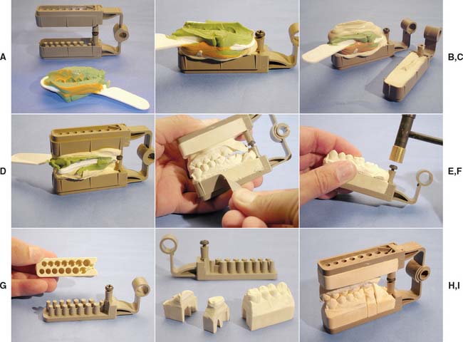
Fig. 17-31 The closed-mouth impression technique using the V2 Quadrant Articulator. A, Trim the double-sided impression flat and parallel to the occlusal plane. B, Pour the prepared tooth side of the impression and the articulator base with die stone. C, Invert the impression and align it onto the articulator base. D, Pour the opposing side of the impression and articulator base. Engage the hinge and close the articulator. E, Once the die stone has fully set, remove the base wall formers. F and G, Eject the die side of the cast by grasping the cast and tapping the base. H and I, Section and trim the cast. The individual dies can be accurately returned to the articulator.
(A to I, Courtesy of Monotrac Articulation, Salt Lake City, Utah.)
Step-by-Step Procedure
SUMMARY
Accurate definitive casts and dies are essential to successful cast restorations. There are various materials and techniques that provide an extremely precise reproduction of the prepared teeth. Type IV stone is recommended in most instances, although it requires careful handling to avoid chipping or abrading margins. Epoxy resin and electroplated silver or copper are durable alternatives. The die of the prepared tooth can be made removable by the use of dowels or the more convenient Pindex system. Alternatively, a solid definitive cast and separate die can be used. Whatever system is chosen, it must articulate precisely with an accurately made opposing cast.
 GLOSSARY*
block out \bl k out\ adj: 1: elimination of undesirable undercuts on a cast, 2: the process of applying wax or another similar temporary substance to undercut portions of a cast so as to leave only those undercuts essential to the planned construction of a prosthesis. A blocked out cast may also include other surface modifications needed relative to the construction of the prosthesis
calcium sulfate plaster \kă′sē-um sŭl′fāt′ plăs′ter\: compounds occurring in anhydrous form as anhydrite, and in the natural form as gypsum or gypsum dehydrate. The term “plaster” also applies to a mixture consisting of water and calcium sulfate hemihydrate (CaSo4. ½H2O)
2cast \kăst\n (14c): a life-size likeness of some desired form. It is formed within or is a material poured into a matrix or impression of the desired form—see DENTAL C., DIAGNOSTIC C., FINAL C., PRELIMINARY C., REFRACTORY C., REMOUNT C.
castable \kăst′a-bl\n (1998): any refractory material that has a bonding agent added and can be mixed with water or other liquid agents and poured in a mold to set
cy·ano·acryl·ate \sī′a-nō-ăk′ra-lāt\ n (20c): a single component, moisture activated, thermoplastic group of adhesives characterized by rapid polymerization and excellent bond strength
definitive cast \d -fn′-tv kăst\: a replica of the tooth surfaces, residual ridge areas, and/or other parts of the dental arch and/or facial structures used to fabricate a dental restoration or prosthesis; called also final cast
dental cast \d n′tl kăst\: a positive life size reproduction of a part or parts of the oral cavity
dental plaster \dn′tl plăs′ter\: the beta-form of calcium sulfate hemihydrate. It is a fibrous aggregate of fine crystals with capillary pores that are irregular in shape and porous in character
dental stone \dn′tl stōn\: the alpha-form of calcium sulfate hemihydrate with physical properties superior to the beta-form (dental plaster). The alpha-form consists of cleavage fragments and crystals in the form of rods or prisms, and is therefore more dense than the beta-form
die \dī\ n (14c): the positive reproduction of the form of a prepared tooth in any suitable substance
dowel pin \dou′al pn\: a metal pin used in stone casts to remove die sections and replace them accurately in the original position
e·lec·tro·plat·ing \-lk′tro-plā′tng\ vt (ca. 1864): the process of covering the surface of an object with a thin coating of metal by means of electrolysis
epoxy resin die \p′k′sē, -pk′- rz′n dī\: a reproduction formed in epoxy resin
gyp·sum \jp′sum\ n (14c): the natural hydrated form of calcium sulfonate, CaSO4 2H2O gypsum dehydrate
master cast : see DEFINITIVE CAST
1mount·ing \moun′tng\ v: the laboratory procedure of attaching a cast to an articulator or cast relater
2mount·ing \moun′-tng\ n: the relationship of dental casts to each other and the instrument to which they are attached; see also—SPLIT-CAST M.
plas·ter \plăs′tar\ n: a paste-like composition (usually of water, lime, and sand) that hardens on drying and is used for coating walls, ceilings, and partitions—slang: in dentistry, a colloquial term applied to dental plaster of paris
split-cast method \splt-kăst mth′ad\ obs: 1: a procedure for placing indexed casts on an articulator to facilitate their removal and replacement on the instrument 2: the procedure of checking the ability of an articulator to receive or be adjusted to a maxillomandibular relation record (GPT-4)
split-cast mounting \splt-kăst moun′tng\: a method of mounting casts wherein the dental cast’s base is sharply grooved and keyed to the mounting ring’s base. The procedure allows verifying the accuracy of the mounting, ease of removal and replacement of the casts
surface tension \sûr′fas tn′shun\: a property of liquids in which the exposed surface tends to contract to the smallest possible area, as in the spherical formation of drops. This is a phenomenon attributed to the attractive forces, or cohesion, between the molecules of the liquid.
tin·foil \tn′foil′\ n (15c): 1: paper thin metal sheeting usually of a tin-lead alloy or aluminum (a misnomer) 2: a base-metal foil used as a separating material between the cast and denture base material during flasking and polymerizing
vacuum mixing \väk′yōō-um mks′ng\: a method of mixing a material such as plaster of paris or casting investment below atmospheric pressure
STUDY QUESTIONS
1 American Dental Association, Council on Dental Materials and Devices. Specification no. 19 for non-aqueous, elastomeric dental impression materials. J Am Dent Assoc. 1977;98:733.
2 Schelb E, et al. Compatibility of type IV dental stone with polysulfide impression materials. J Prosthodont. 1992;1:32.
3 Omana HM, et al. Compatibility of impressions and die stone material. Oper Dent. 1990;15:82.
4 Toreskog S, et al. Properties of die materials: a comparative study. J Prosthet Dent. 1966;16:119.
5 Fukui H, et al. Effectiveness of hardening films on die stone. J Prosthet Dent. 1980;44:57.
6 Campagni WV, et al. Measurement of coating agents used for surface protection of stone dies. J Prosthet Dent. 1986;55:470.
7 Zakaria MR, et al. The effects of a liquid dispersing agent and a microcrystalline additive on the physical properties of type IV gypsum. J Prosthet Dent. 1988;60:630.
8 Alsadi S, et al. Properties of gypsum with the addition of gum arabic and calcium hydroxide. J Prosthet Dent. 1996;76:530.
9 Wee AG, et al. Evaluation of the accuracy of solid implant casts. J Prosthodont. 1998;7:161.
10 Yaman P, Brandau HE. Comparison of three epoxy die materials. J Prosthet Dent. 1986;55:328.
11 Chaffee NR, et al. Dimensional accuracy of improved dental stone and epoxy resin die materials. I. Single die. J Prosthet Dent. 1997;77:131.
12 Schaffer H, et al. Distance alterations of dies in sagittal direction in dependence of the die material. J Prosthet Dent. 1989;61:684.
13 Chaffee NR, et al. Dimensional accuracy of improved dental stone and epoxy resin die materials. II. Complete arch form. J Prosthet Dent. 1997;77:235.
14 Derrien G, Le Menn G. Evaluation of detail reproduction for three die materials by using scanning electron microscopy and two-dimensional profilometry. J Prosthet Dent. 1995;74:1.
15 Nomura GT, et al. An investigation of epoxy resin dies. J Prosthet Dent. 1980;44:45.
16 Stackhouse JA. Electrodeposition in dentistry: a review of the literature. J Prosthet Dent. 1980;44:259.
17 Crispin BJ, et al. Silver-plated dies. II. Marginal accuracy of cast restorations. J Prosthet Dent. 1984;51:768.
18 Cassimaty EM, Walton TR. Effect of three variables on the accuracy and variability of electroplated copper dies. Int J Prosthodont. 1996;9:547.
19 Crispin BJ, et al. Silver-plated dies. I. Platability of impression materials. J Prosthet Dent. 1984;51:631.
20 Nash RW, Rhyne KM. New flexible model technique for fabricating indirect composite inlays and onlays. Dent Today. 1990;9:26.
21 Roberts DB. Flexible casts used in making indirect interim restorations. J Prosthet Dent. 1992;68:372.
22 Rada RE. In-office fabrication of indirect composite-resin restorations. Pract Periodont Aesthet Dent. 1992;4:25.
23 Trushkowsky RD. One-visit composite onlay utilizing a new flexible model material. Am J Dent. 1997;1:55.
24 Gerrow JD, Price RB. Comparison of the surface detail reproduction of flexible die material systems. J Prosthet Dent. 1998;80:485.
25 Smith CD, et al. Fabrication of removable stone dies using cemented dowel pins. J Prosthet Dent. 1979;41:579.
26 Serrano JG, et al. An accuracy evaluation of four removable die systems. J Prosthet Dent. 1998;80:575.
27 Aramouni P, Millstein P. A comparison of the accuracy of two removable die systems with intact working casts. Int J Prosthodont. 1993;6:533.
28 Covo LM, et al. Accuracy and comparative stability of three removable die systems. J Prosthet Dent. 1988;59:314.
29 Chong YH, et al. Relationship between contact angles of die stone on elastomeric impression materials and voids in stone casts. Dent Mater. 1990;6:162.
30 Lepe X, et al. Effect of mixing technique on surface characteristics of impression materials. J Prosthet Dent. 1998;79:495.
31 Vassilakos N, Fernandes CP. Surface properties of elastomeric impression materials. J Dent. 1993;21:297.
32 Boening KW, et al. Clinical significance of surface activation of silicone impression materials. J Dent. 1998;26:447.
33 Balshi TJ, Mingledorff EB. Matches, clips, needles, or pins. J Prosthet Dent. 1975;34:467.
34 Walker PM. Discrepancies between arbitrary and true hinge axes. J Prosthet Dent. 1980;43:279.
35 Bowley JF, et al. Reliability of a facebow transfer procedure. J Prosthet Dent. 1992;67:491.
36 Peregrina A, Reisbick MH. Occlusal accuracy of casts made and articulated differently. J Prosthet Dent. 1990;63:422.
37 Weinberg LA. An evaluation of the face-bow mounting. J Prosthet Dent. 1961;11:32.
38 Wilson EG, Werrin SR. Double arch impressions for simplified restorative dentistry. J Prosthet Dent. 1983;49:198.
39 Donovan TE, Chee WWL. A review of contemporary impression materials and techniques. Dent Clin North Am. 2004;48:445.