12 RESTORATION OF THE ENDODONTICALLY TREATED TOOTH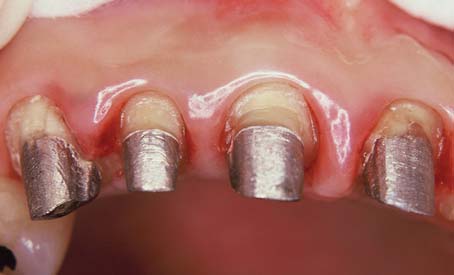
An endodontically treated tooth should have a good prognosis. It can resume full function and serve satisfactorily as an abutment for a fixed dental prosthesis (FDP) or a removable partial dental prosthesis. However, special techniques are needed to restore such a tooth. Usually a considerable amount of tooth structure has been lost because of caries, endodontic treatment, and the placement of previous restorations. The loss of tooth structure makes retention of subsequent restorations more problematic and increases the likelihood of fracture during functional loading.
Two factors influence the choice of technique: the type of tooth (whether it is an incisor, canine, premolar, or molar) and the amount of remaining coronal tooth structure. The latter is probably the most important indicator in determining the prognosis.
A number of different clinical techniques have been proposed to solve these problems, and opinions vary about the most appropriate one. Experimental data have improved the understanding of the difficulties inherent in restoring endodontically treated teeth. This chapter offers a rational and practical approach to the challenge.
TREATMENT PLANNING
Because of extensive caries or periodontal disease, removal of a tooth may be more sensible than endodontically treating it, although a severely damaged tooth occasionally can be restored after orthodontic repositioning or root resection (Fig. 12-1; see also Fig. 16-7). This should be done if loss of the tooth will significantly jeopardize the patient’s occlusal function or the total treatment plan, particularly if dental implants are not an option. When the decision is made to treat the tooth endodontically, consideration must have been given to its subsequent restoration. Before being restored, teeth that have been endodontically treated must be carefully evaluated for the following1:
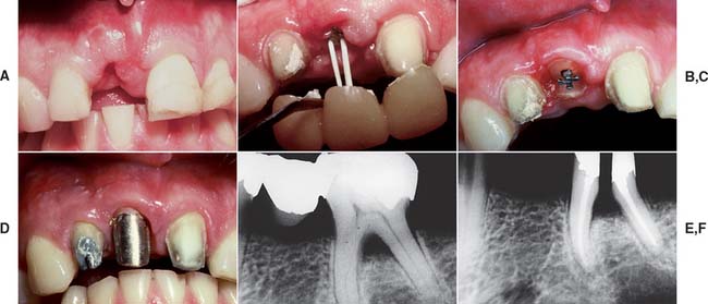
Fig. 12-1 A to D, A severely damaged tooth can sometimes be retained after orthodontic extrusion (see Chapter 6). E and F, Plaque control around periodontally compromised teeth may be improved after hemisectioning (see Chapter 5).
(E and F, Courtesy of Dr. H. Kahn.)
Inadequate root fillings should be re-treated before fixed prosthodontic treatment is begun. If doubt remains, the tooth should be observed for several months until there is definite evidence of success or failure.
If the coronal structures are largely intact and loading is favorable, as on anterior teeth that are farther removed from the fulcrum (see Chapter 4), a simple filling can be placed in the access cavity (Fig. 12-2A). However, if a substantial amount of coronal structure is missing, a cast post and core is indicated instead (Fig. 12-2B). Molars are often restored with amalgam or a combination of one or more cemented posts and amalgam or composite resin (Fig. 12-2C and D).
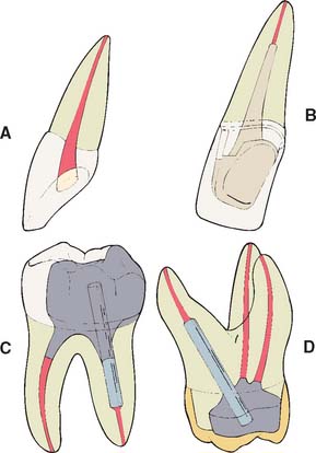
Fig. 12-2 A, An anterior tooth with an intact clinical crown can be predictably restored with a composite restoration in the access cavity. B, When most coronal tissue is missing, a cast post and core is indicated to obtain optimal tooth preparation form. C, In mandibular molars, an amalgam foundation is retained by a cemented prefabricated post in the distal canal. D, In maxillary molars, the palatal canal is most often used.
Although one-piece post-crowns were once made, such prostheses are of only historical interest. Superior results are obtained with a two-step technique (Fig. 12-3) consisting of initial placement of a post and core foundation followed by placement of a separately fabricated crown. Most often a metal post is used, which provides the necessary retention for the core. The core replaces any lost coronal tooth structure, allowing optimal tooth preparation geometry to be achieved. Thus, the shape of the residual coronal tooth structure, combined with the core, should result in an ideal shape for the preparation (Fig. 12-4).
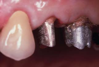
Fig. 12-3 The first molar and second premolar have been restored with post and cores. Note the margins, optimally located on sound tooth structure, cervical to the castings.
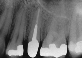
Fig. 12-4 The second premolar has been restored with a cast post and core, before a metal-ceramic crown.
(Courtesy of Dr. R. Webber.)
Prefabricated metal, carbon fiber, ceramic, and glass fiber posts are available. The last two options provide esthetic alternatives to metal posts.2,3 Typically, prefabricated posts are used in a two-step procedure: first the post is cemented, after which a plastic core material such as composite resin, amalgam, or glass ionomer is applied. After shaping of the core and remaining tooth structure to optimal crown preparation form, a crown is fabricated in the conventional manner.
A cast post and core needs to be slightly undersized compared with the canal to achieve optimal internal seating, whereas the crown needs to be slightly larger to achieve optimal seating (see Chapter 7). Thus, it is easier to achieve a satisfactory marginal adaptation because the expansion rate of the two castings can be controlled individually. An added benefit is that it is possible to fabricate a replacement crown, if necessary, without the need for post removal, which may jeopardize the prognosis of the tooth. Finally, a path of placement different from the one selected for the post and core may be selected for the crown. This is often helpful when the tooth is restored to serve as an abutment for an FDP.
Clinical Failure
Morphologic and functional differences between anterior teeth and posterior teeth necessitate that they be treated differently after endodontic therapy, mainly because different loading considerations apply.
In one retrospective analysis4 involving 638 patients, investigators evaluated 788 post and cores: 456 custom cast post and cores and 332 foundations with ParaPosts. Four to five years after cementation, reported failure rates in male patients were significantly higher than in female patients, and failure rates after age 60 were three times as high as failure rates for younger patients. Maxillary failure rates (15%) were three times as high as mandibular failure rates (5%) and more prevalent in lateral incisors, canines, and premolars than in central incisors and molars. Failure rate under FDPs was significantly lower than under single crowns. The latter finding may have been caused by load reduction resulting from bracing by the FDP. No correlation was apparent between failure and reduced marginal height of the encasing bone. Custom cast post and cores exhibited slightly higher failure rates than did amalgam foundations. This observation was also made by Sorensen and Martinoff.5 However, Torbjörner and colleagues4 suggested that custom cast post and cores tend to be used more often in teeth that already have considerably weakened root structure. Thus, regardless of the technique selected for subsequent restoration, the teeth themselves are already more prone to failure. Distal cantilevers appear to contribute to post and core failure in endodontically treated abutment teeth that support the cantilever.
Most of the failures just discussed are influenced by load. In general, as loading increases, failure rates appear to increase concomitantly. Failure has been shown to occur at lower loads as teeth are loaded less parallel to their long axes,6 which suggests that clinical failure occurs more readily under lateral loading.
In the planning of the restoration of endodontically treated teeth, the practitioner must account for the strength of the remaining tooth structure, weighed carefully against the load to which the restored tooth will be subjected.
Considerations for Anterior Teeth
Endodontically treated anterior teeth do not always need complete coverage by placement of a complete crown, except when plastic restorative materials have limited prognosis (e.g., if the tooth has large proximal composite restorations and unsupported tooth structure). Many otherwise intact teeth function satisfactorily with a composite resin restoration.
Although it is commonly believed, it has not been demonstrated experimentally that endodontically treated teeth are weaker or more brittle than vital teeth. Their moisture content, however, may be reduced.7 Laboratory testing8 has actually revealed a resistance to fracture similar between untreated and endodontically treated anterior teeth. Nevertheless, clinical fracture does occur, and attempts have been made to strengthen the tooth by removing part of the root canal filling and replacing it with a metal post. In reality, placement of a post requires the removal of additional tooth structure (Box 12-1), which is likely to weaken the tooth.
Box 12-1 Disadvantages to the Routine Use of a Cemented Post
Placing the post requires an additional operative procedure.
Preparing a tooth to accommodate the post entails removal of additional tooth structure.
It may be difficult to restore the tooth later, when a complete crown is needed, because the cemented post may have failed to provide adequate retention for the core material.
The post can complicate or prevent future endodontic re-treatment that may be necessary.
Cementing a post in an endodontically treated tooth is a fairly common clinical procedure, despite the paucity of data to support its success. In fact, a laboratory study9 and two stress analyses10,11 have determined that no significant reinforcement results. This might be explained by the hypothesis that when the tooth is loaded, stresses are greatest at the facial and lingual surfaces of the root and an internal post, being only minimally stressed, does not help prevent fracture (Fig. 12-5). Results of other studies, however, contradict this assumption.8,12 Cemented posts may further limit or complicate endodontic re-treatment options if these are necessary. In addition, if coronal destruction occurs, post removal may be necessary to provide adequate support for a future core.
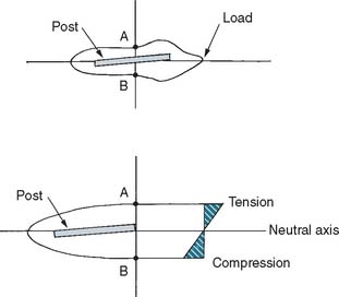
Fig. 12-5 Experimental stress distributions in an endodontically treated tooth with a cemented post. When the tooth is loaded, the lingual surface (A) is in tension, and the facial surface (B) is in compression. The centrally located cemented post lies in the neutral axis (i.e., not in tension or compression).
(Redrawn from Guzy GE, Nicholls JI: In vitro comparison of intact endodontically treated teeth with and without endo-post reinforcement. J Prosthet Dent 42:39, 1979.)
For these reasons, a metal post is not recommended in anterior teeth that do not require complete coverage restorations. This view is supported by a retrospective study13 that did not show any improvement in prognosis for endodontically treated anterior teeth restored with a post. In another study, post placement did not influence the position or angle of radicular fracture.14 A conflicting report however, suggests that endodontically treated teeth not crowned after obturation were lost six times more frequently than teeth that were crowned after obturation.15
Discoloration in the absence of significant tooth loss may be more effectively treated by bleaching16 than by the placement of a complete crown, although not all stained teeth can be bleached successfully. Resorption can be an unfortunate side effect of nonvital bleaching.17 However, when loss of coronal tooth structure is extensive or the tooth will be serving as an FDP or partial removable dental prosthetic abutment, a complete crown becomes mandatory. Retention and support then must be derived from within the canal, because a limited amount of coronal dentin remains once the reduction for complete coverage has been completed. Coupled with the loss of internal tooth structure necessary for endodontic treatment, the remaining walls become thin and fragile (Fig. 12-6), which often necessitates their reduction in height.
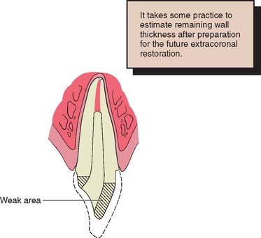
Fig. 12-6 Cross section through a central incisor. The dotted line indicates the original tooth contour before preparation for a metal-ceramic restoration. Even with minimum reduction for the extracoronal restoration, the facial wall is weakened and would not be able to support a prosthesis successfully. The sharp lingual wall complicates pattern fabrication.
Considerations for Posterior Teeth
Posterior teeth are subject to greater loading than are anterior teeth because of their closer proximity to the transverse horizontal axis. This, combined with their morphologic characteristics (having cusps that can be wedged apart), makes them more susceptible to fracture. Careful occlusal adjustment reduces potentially damaging lateral forces during excursive movements. Nevertheless, endodontically treated posterior tooth should receive cuspal coverage to prevent biting forces from causing fracture. Possible exceptions are mandibular premolars and first molars with intact marginal ridges and conservative access cavities not subjected to excessive occlusal forces (i.e., posterior disclusion in conjunction with normal muscle activity).
Complete coverage is recommended on teeth with a high risk of fracture. This is especially true for maxillary premolars, which have been shown to have fairly high failure rates if restored with two or three surface amalgam restorations.18 Complete coverage gives the best protection against fracture, because the tooth is completely encircled by therestoration. However, when a metal-ceramic crown is to be used, considerable tooth reduction is required, which results in further weakening of the remaining tooth structure. In general, when significant coronal tooth loss has occurred, a cast post and core (Fig. 12-7) or an amalgam foundation restoration is needed.
PRINCIPLES OF TOOTH PREPARATION
Many of the principles of tooth preparation discussed in Chapter 7 apply equally to the preparation of endodontically treated teeth, although certain additional concepts must be understood in order to avoid failure.
Conservation of Tooth Structure
Preparation of the canal
In creating post space, great care must be used to remove only minimal tooth structure from the canal (Fig. 12-8). Excessive enlargement can perforate or weaken the root, which then may split during post cementation or subsequent function. The thickness of the remaining dentin is the prime variable in fracture resistance of the root. Experimental impact testing of teeth with cemented posts of different diameters7 showed that teeth with a thicker (1.8 mm) post fractured more easily than those with a thinner (1.3 mm) one.
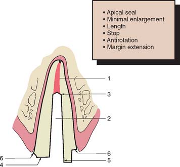
Fig. 12-8 Faciolingual cross-section through a maxillary central incisor prepared for a post and core. Six features of successful design are identified: 1, adequate apical seal; 2, minimum canal enlargement (no undercuts remaining); 3, adequate post length; 4, positive horizontal stop (to minimize wedging); 5, vertical wall to prevent rotation (similar to a box); and 6, extension of the final restoration margin onto sound tooth structure.
Photoelastic stress analysis also has shown that internal stresses are reduced with thinner posts. The root can be compared to a ring. The strength of a ring is proportional to the difference between the fourth powers of its internal and external radii. This implies that the strength of a prepared root comes from its periphery, not from its interior, and so a post of reasonable size should not weaken the root significantly.19 Nevertheless, it is difficult to enlarge a root canal uniformly and to judge with accuracy how much tooth structure has been removed and how thick the remaining dentin is. Most roots are narrower mesiodistally than faciolingually and often have proximal concavities that cannot be seen on a standard periapical radiograph. Experimentally, most root fractures originate from these concavities, because the remaining dentin thickness is minimal.20 Therefore, the root canal should be enlarged only enough to enable the post to fit accurately and yet passively while ensuring strength and retention. Along the length of a tapered post space, enlargement seldom needs to exceed what would have been accomplished with one or two additional file sizes beyond the largest size used for endodontic treatment. Because of the more coronal position of the post space, a much larger file must be used to accomplish this (Fig. 12-9).
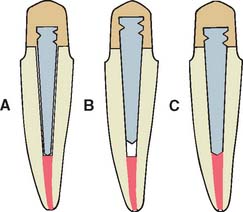
Fig. 12-9 Use of a prefabricated post entails enlarging the canal one or two file sizes to obtain a good fit at a predetermined depth. A, Incorrect; the prefabricated post is too narrow. B, Incorrect; the prefabricated post does not extend to the apical seal. C, Correct; the prefabricated post is fitted by enlarging the canal slightly.
Preparation of coronal tissue
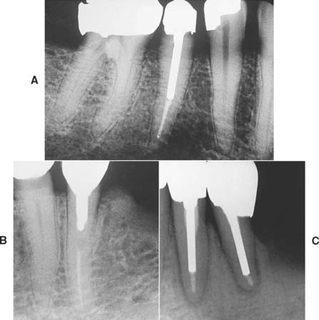
Endodontically treated teeth often have lost much coronal tooth structure as a result of caries, as a result of previously placed restorations, or in preparation of the endodontic access cavity. However, if a cast core is to be used, further reduction is needed to accommodate a complete crown and to remove undercuts from the chamber and internal walls. This may leave very little coronal dentin. Every effort should be made to save as much of the coronal tooth structure as possible, because this helps reduce stress concentrations at the gingival margin.21 The amount of remaining tooth structure is probably the most important predictor of clinical success. If more than 2 mm of coronal tooth structure remains, the post design probably has a limited role in the fracture resistance of the restored tooth.22,23 The once common clinical practice of routine coronal reduction to the gingival level before post and core fabrication is outmoded and should be avoided (Fig. 12-10). Extension of the axial wall of the crown apical to the missing tooth structure provides what is known as a restoration with a ferrule, which is defined as a metal band or ring used to fit the root or crown of a tooth, as opposed to a crown that merely encircles core material (Fig. 12-11). This is thought to help bind the remaining tooth structure together, simultaneously preventing root fracture during function.24-26 Although there is evidence that preserving as much coronal tooth structure as possible enhances prognosis, it is less clear whether the prognosis is improved by creation of a ferrule in an extensively damaged tooth through a surgical crown-lengthening procedure. In this latter circumstance, although the crown lengthening allows fabrication of a crown with a ferrule, it also leads to a much less favorable crown/root ratio and therefore to increased leverage on the root during function (Fig. 12-12).
Fig. 12-10 A, It is preferable to maintain as much coronal tooth structure as possible, provided it is sound and of reasonable strength. B, Extensive caries has resulted in the loss of all coronal tooth structure. This is less desirable than the situation in A, because greater forces are transmitted to the root.
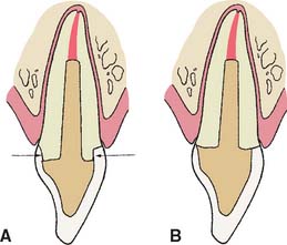
Fig. 12-11 Extending a preparation apically creates a ferrule and helps prevents fracture of an endodontically treated tooth during function. A, Preparation with a ferrule (arrows). B, Preparation without a ferrule.

Fig. 12-12 Effect of apical preparation on crown/root ratio. A, Schematic of extensively damaged premolar tooth. Apical extension of the gingival margin would encroach on the biologic width (Chapter 5). This preparation has no ferrule. C, crown length; R, root length. B, Creating a ferrule with orthodontic extrusion (see Fig. 6-21) reduces root length (R′), whereas crown length remains unchanged. C, Surgical crown lengthening also reduces root length (R′) but increases crown length (C′). This results in a much less favorable crown/root ratio, which may, in fact, weaken the restoration.
(Courtesy of Dr. A. G. Gegauff. From Gegauff AG: Effect of crown lengthening and ferrule placement on static load failure of cemented cast post-cores and crowns, J Prosthet Dent 84:169, 2000.)
One laboratory study showed that creating a ferrule through surgical crown lengthening resulted in a weaker, rather than a stronger, restored tooth.27 In comparison, creating a ferrule with orthodontic extrusion may be preferred, because even though theroot is effectively shortened, the crown is not lengthened (see Fig. 12-12B).
Retention Form
Anterior teeth
Simultaneous dislodgment of an anterior crown with the post and core that retains it is frequently seen clinically and results from inadequate retention form of the prepared tooth.13,28 The normal faciolingual convergence of anterior teeth, coupled with smaller tooth size, complicates achieving such retention form. Post retention is affected by the preparation geometry, post length, post diameter, post surface texture, and the luting agent.
Preparation geometry
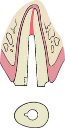
Some canals, particularly in maxillary central incisors, have a nearly circular cross-section (see Table 12-3). These can be prepared with a twist drill or reamer to provide a cavity with parallel walls or minimal taper, allowing the use of a preformed post of corresponding size and configuration. Conversely, canals with elliptical cross-sections must be prepared with a restricted amount of taper (usually 6 to 8 degrees) to ensure adequate retention and eliminate undesired undercuts. This is analogous to an extracoronal preparation (see Chapter 7). With extracoronal preparations, retention increases rapidly as vertical wall taper is reduced (see Chapter 7). Although retention can be further increased by use of a threaded post, which screws into dentin, this procedure is not recommended because of residual stress in the dentin. If the procedure is used, however, threaded posts must be “backed off” to ensure passivity; otherwise, the root will fracture.
Table 12-3 ROOT CANAL CONFIGURATIONS
| Circular | Elliptical | |
|---|---|---|
| Buccolingual | Mesiodistal | |
| Maxillary central incisor | ||
| Maxillary first premolar (two roots) | ||
| Mandibular second premolar | Maxillary second premolar | |
| Maxillary molars (distobuccal roots) | Maxillary molars (palatal roots) | |
From Weine FS: Endodontic Therapy, 4th ed, pp 225–269. St. Louis, Mosby, 1989.
In accordance with this explanation, laboratory testing29-31 has confirmed that parallel-sided posts are more retentive than tapered posts and that threaded posts are the most retentive (Fig. 12-13). However, these comparisons are relevant only if the post fits the root canal properly, because retention is proportional to the total surface area.
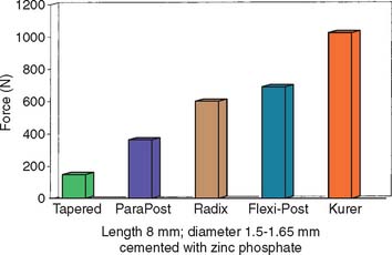
Fig. 12-13 Comparison of forces needed to remove different prefabricated post systems.
(Redrawn from Standlee JP, Caputo AA: The retentive and stress distributing properties of split threaded endodontic dowels. J Prosthet Dent 68:436, 1992.)
Circular parallel-sided post systems are effective only in the most apical portion of the post space, because the majority of prepared post spaces demonstrate considerable flare in the occlusal half. Similarly, when the root canal is elliptical, a parallel-sided post is not effective unless the canal is considerably enlarged, which would significantly weaken the root unnecessarily (Fig. 12-14).
Post length
Studies29,31,32 have shown that as post length increases, so does retention. However, the relationship is not necessarily linear (Fig. 12-15). A post that is too short will fail (Fig. 12-16), whereas one that is too long may damage the seal of the root canal fill or risk root perforation if the apical third is curved or tapered (Fig. 12-17). Absolute guidelines for optimal post length are difficult to define. Ideally, the post should be as long as possible without jeopardizing the apical seal or the strength or integrity of the remaining root structure. Most endodontic texts advocate maintaining a 5-mm apical seal. However, if a post is shorter than the coronal height of the clinical crown of the tooth, the prognosis is considered unfavorable, because stress is distributed over a smaller surface area, thereby increasing the probability of radicular fracture. A short root and a tall clinical crown present the clinician with the dilemma of having to compromise the mechanics, the apical seal, or both. Under such circumstances, an apical seal of 3 mm is considered acceptable.
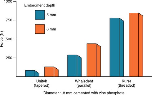
Fig. 12-15 Effect of the depth of embedding a post on its retentive capacity.
(Data from Standlee JP, et al: Retention of endodontic dowels: effects of cement, dowel length, diameter, and design. J Prosthet Dent 39:401, 1978.)
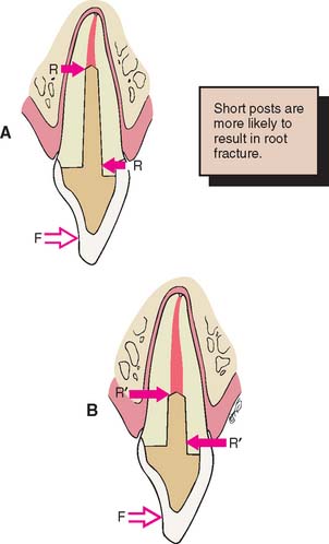
Fig. 12-16 Faciolingual longitudinal sections through a maxillary central incisor. A, With a post of the correct length, a force (F) applied near the incisal edge of the crown generates a resultant couple (R). B, When the post is too short, this couple is greater (R′), which leads to the increased possibility of root fracture.
Post diameter
Increasing the post diameter in an attempt to increase retention is not recommended because the results are minimal retentive gain and unnecessary weakening of the remaining root. Although one group of investigators33 reported that increasing the post diameter increased retention, other reports do not confirm this.29,30 Empirical evidence suggests that the overall prognosis is good when post diameter does not exceed one third of the cross-sectional root diameter.
Post surface texture
A serrated or roughened post is more retentive than a smooth one,30 and controlled grooving of the post and root canal34 (Fig. 12-18) considerably increases the retention of a tapered post.
Luting agent
In considering traditional cements, the choice of luting agent seems to have little effect on post retention35,36 or the fracture resistance of dentin.37 However, adhesive resin luting agents (see Chapter 31) have the potential to improve the performance of post and core restorations; laboratory studies have shown improved retention.38,39 Resin cements may be indicated if a post becomes dislodged. Resin cements are affected by eugenol-containing root canal sealers, which should be removed by irrigation with ethanol or etching with 37% phosphoric acid if the adhesive is to be effective.40 Zinc phosphate and glass ionomer have comparable retentive properties, whereas polycarboxylate and composite resin cements have slightly less.41 Some resin and glass ionomer cements have demonstrated significantly higher retention than resin-ionomer cements,42 although the choice of luting agent may become more important if the post has a poor fit within the canal.43 A post and core should be remade if any rotation or wobble is present.
Posterior teeth
Relatively long posts with a circular cross-section provide good retention and support in anterior teeth but should be avoided in posterior teeth, which often have curved roots and elliptical or ribbon-shaped canals (Fig. 12-19). For these teeth, retention is better provided by two or more relatively short posts in the divergent canals.
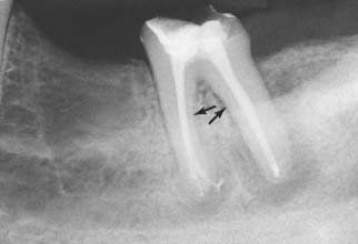
Fig. 12-19 When preparing posterior teeth for intracoronal retention, the practitioner must be careful to avoid perforation, especially on the distal surface of mesial roots and the mesial surface of distal roots, where residual tooth structure is normally thinnest and where concavities are often present (arrows).
When amalgam is used as the core material, it can be condensed either around cemented metal posts or directly into short, prepared post spaces. If a reasonable amount of coronal tissue remains, use of a single metal post that is cemented in the largest canal can provide adequate retention for the core material. When more than 3 to 4 mm of coronal tooth structure with reasonable wall thickness remains, use of a post in the root canals for retention is not necessary, and this reduces the risk of perforation.44 When a post is not used, the chamber must provide adequate retention for the core material. It may then be advantageous to prepare several short divergent post spaces into which the core material extends. Use of the canals for retention can provide good results,45 although once a complete crown has been provided, the strength of the tooth is not dramatically influenced by differences in technique.
Mandibular premolars and molars with a reasonable amount of remaining coronal tooth structure, when coupled with a circumferential cervical band of tooth structure with restricted taper of about 2 mm, can often be restored with amalgam directly condensed into the chamber. Core buildups in molars with one or more missing cusps benefit from one or more cemented posts around which the amalgam can be condensed. The posts provide the additional retention, which was compromised because of the missing tooth structure. In mandibular molars, the larger distal canal is recommended for post placement. In maxillary molars, the palatal canal is used (see Fig. 12-2C and D).
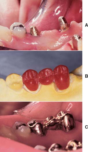
Although it is possible to restore a severely compromised molar with three or more missing cusps with multiple posts and amalgam, the tooth’s overall importance must be assessed, as the prognosis of such teeth is often guarded. If retaining the tooth is crucial and optimal strength is needed, a multipiece cast core can be used (made in sections that have different paths of withdrawal) (Fig. 12-20). An alternative preparation method for a posterior tooth is selecting the canals that are widest (normally the palatal of maxillary molars and the distal of mandibular molars) for the major post and then preparing short auxiliary post spaces in the other canals with the same path of withdrawal (Fig. 12-21).
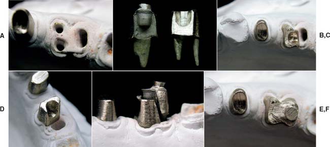
Fig. 12-20 A to F, Cast cores for posterior teeth can be made in interlocking sections, with each section having its own path of withdrawal.
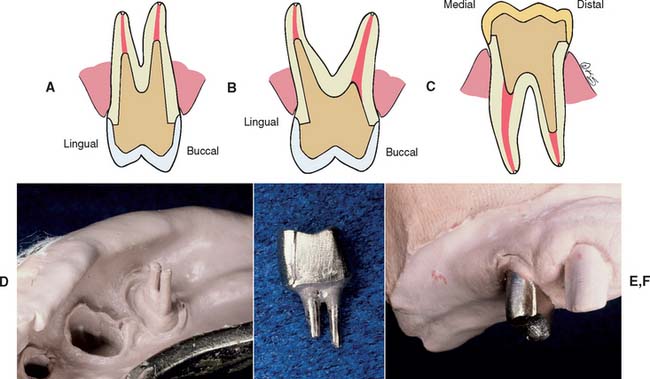
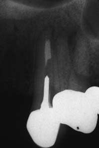
Fig. 12-21 Single-piece castings can be made by selecting the larger-diameter canal and extending a second post for a limited distance into the smaller canal. A, A maxillary first premolar. B, A maxillary first molar. C, A mandibular first molar. D to F, Post and core provided for a maxillary first premolar by the indirect technique.
Resistance Form
Stress distribution
One of the functions of a post and core is to improve resistance to laterally directed forces by distributing them over as large an area as possible. However, excessive internal preparation of the root weakens it, and the risk of failure increases. The post design should distribute stresses as evenly as possible. The incidence of radicular fracture increases with the use of threaded posts that actively engage radicular dentin, and threaded flexible posts do not appear to reduce stress concentrations during function.
The influence of post design on stress distribution has been tested with photoelastic materials,20,32,46-48 strain gauges,49,50 and finite element analysis.51,52 From these laboratory studies, the following conclusions have been drawn:
Rotational resistance
To minimize the risk of dislodgment, it is important that preparation geometry prevents a post with a circular cross-section from rotating during function (Fig. 12-22). This usually does not present a problem when sufficient coronal tooth structure remains, because rotation is prevented by a vertical coronal wall. Where coronal dentin has been completely lost, a small groove placed in the canal wall can serve as an antirotational element. The groove is normally located where the root is bulkiest, usually on its lingual aspect. Alternatively, rotation can be prevented by an auxiliary pin in the root face. Rotation of a threaded post can also be prevented31 by preparing a small cavity (half in the post, half in the root) and condensing amalgam into it after the post is cemented.
PROCEDURES
Tooth preparation for endodontically treated teeth can be considered a three-stage operation:
Removal of the Endodontic Filling Material
The root canal system should first be completely filled; space should then be made for a post, thus ensuring that lateral canals are sealed. A post cannot be placed if the canal is filled with a full-length silver point, so these must be removed and the tooth retreated with gutta-percha. It is not advisable to shorten previously cemented silver points, because leakage will result even if only a short portion is removed.53,54
There are two commonly used methods to remove gutta-percha (Fig. 12-23): (1) using a warmed endodontic plugger, and (2) using a rotary instrument, sometimes in conjunction with chemical agents. Although more time consuming, the warmed endodontic plugger is preferred because it eliminates the possibility that the rotary instrument will inadvertently damage the dentin. If it is more convenient, the gutta-percha can be removed with a warmed condenser immediately after obturation. This does not disturb the apical seal.55,56 This method offers the additional advantage of allowing the operator to work in an area where the root canal anatomy is still familiar.
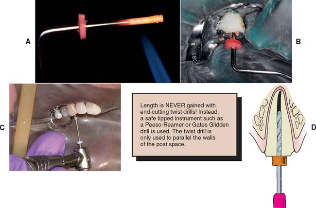
Fig. 12-23 Gutta-percha can be removed from the canal with a heated endodontic plugger. (A and B), a non–end-cutting bur (C) (e.g., a Gates Glidden drill). A ParaPost drill (D) can be used to parallel the post space wall (with a rubber stop to ensure accuracy of the preparation depth).
(A and B, Courtesy of Dr. D. A. Miller.)
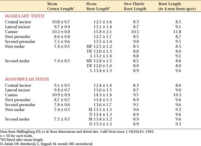
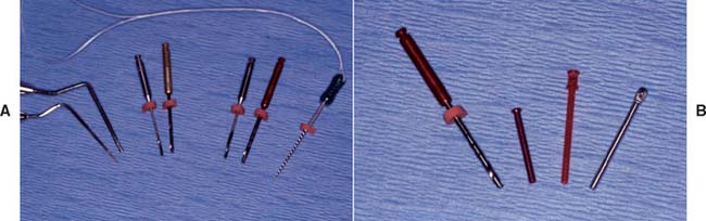
Fig. 12-24 Commonly used instruments for gutta-percha removal and canal enlargement. A, Endodontic pluggers, two sizes of Peeso-Reamers with corresponding twist drills, and endodontic file. Note attached floss as a safety precaution. B, The ParaPost twist drill corresponds in size to an aluminum post used to fabricate interim restorations, a plastic post for patterns, and a stainless-steel or titanium post.
(Courtesy of Dr. J. A. Nelson.)
Of importance: End-cutting instruments should never be used to gain length because root perforation will result!
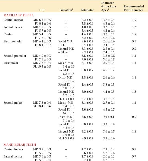
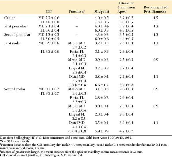
The post should be no more than one-third the root diameter,1,59 with the root and walls at least 1 mm thick. Obviously, for deciding on appropriate post diameters, a knowledge of average root dimensions is important. These have been calculated60 and are presented in Table 12-2. Knowledge of root canal cross-section also is significant in post selection. Prefabricated posts are circular in cross-section, but many root canals are elliptical, which makes uniform reduction with a drill impossible. Canal shapes are summarized in Table 12-3.
Enlargement of the Canal
Before enlargement of the canal, the type of post system to be used for fabrication of the post and core must be chosen.
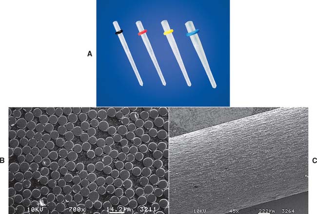
The advantages and disadvantages of different post types are summarized in Table 12-4. Because no system has universal application, being familiar with more than one technique is a significant advantage. A wide range of prefabricated posts are available. They come in many shapes and sizes and have varying radiopacity that may assist in their identification (Table 12-5 and Figs. 12-25 and 12-26).
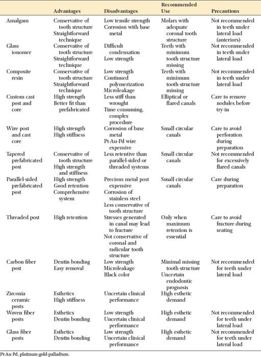
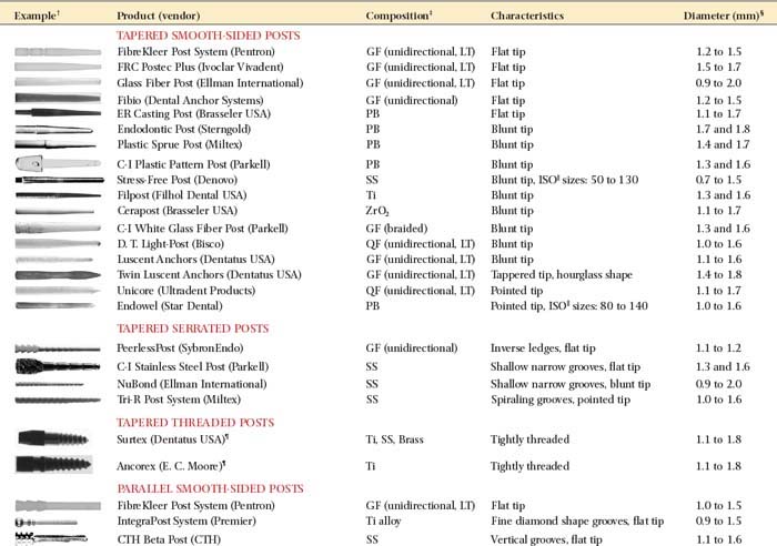
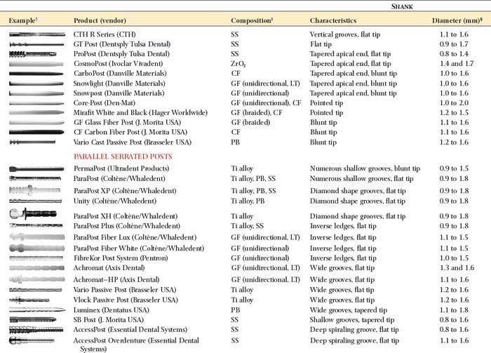
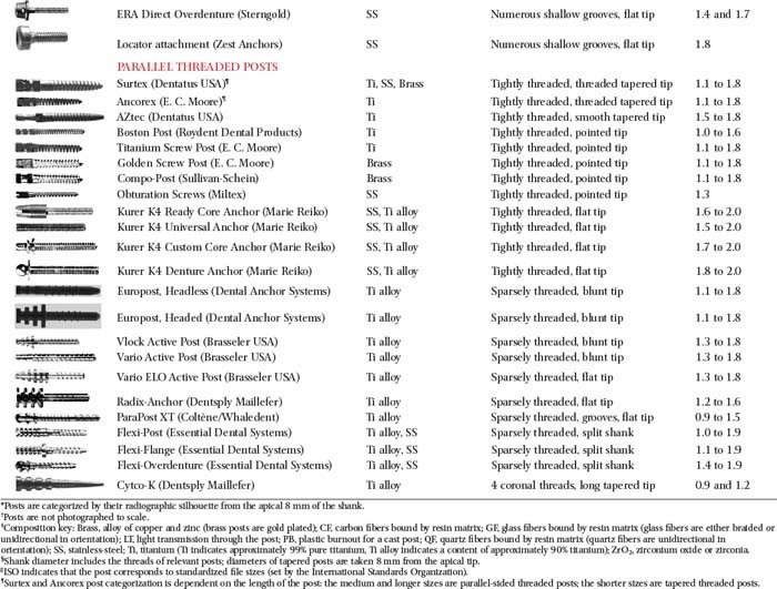
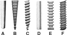
Fig. 12-25 Classification of prefabricated posts. A, Tapered smooth posts. B, Tapered serrated posts. C, Tapered threaded posts. D, Parallel-sided smooth posts. E, Parallel-sided serrated posts. F, Parallel-sided threaded posts.
(Redrawn from Shillingburg HT, Kessler JC: Restoration of the Endodontically Treated Tooth. Chicago, Quintessence Publishing, 1982.)
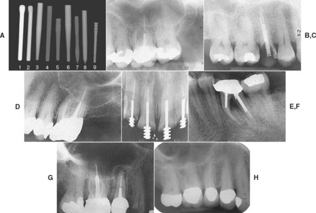
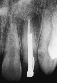
Fig. 12-26 The various endodontic posts encountered in clinical practice present with varying degrees of radiopacity. Dentists accustomed to seeing traditional stainless steel and titanium posts may be deceived by more recently introduced systems. A, Nine representative posts: (1) ParaPost stainless steel (Coltène/Whaledent); (2) ParaPost titanium (Coltène/Whaledent); (3) FRC Postec Plus (Ivoclar Vivadent); (4) Glass Fiber Post (Ellman International); (5) Glass Fiber C-I Post (Parkell); (6) D. T. Light-Post (Bisco); (7) Twin Luscent Anchors (Dentatus USA); (8) Unicore (Ultradent Products); (9) PeerlessPost (SybronEndo). The pure carbon fiber posts (not included in A) are completely radiolucent. The type of cement that is used plays a role in the radiopacity of the post (see Fig. 31-6). B to I, Radiographs of the six categories: B, Endowel (Star Dental), tapered and smooth sided. C, Unimetric (DENTSPLY), tapered and serrated. D, Surtex (Dentatus USA), tapered and threaded. E, CTH Beta Post (CTH), parallel-sided and smooth. F, ParaPost (Coltène/Whaledent) (two sizes), parallel-sided and serrated. G, Flexi-Post (Essential Dental Systems) (in the right maxillary first molar), parallel-sided and threaded (note the split shank). H, ParaPost Fiber Lux (Coltène/Whaledent) cemented with RelyX Luting (3M ESPE). Note the radiolucency of the post in comparison with the radiopacity of the gutta-percha endodontic fill.
(B, Courtesy of Dr. D. A. Miller and Dr. H. W. Zuckerman; C, courtesy of Dr. I. A. Roseman; D, courtesy of Dr. F. S. Weine and Dr. S. Strauss; E, courtesy of Dr. J. F. Tardera; F, courtesy of Dr. J. L. Wingo; G, courtesy of Dr. L. R. Farsakian; H, courtesy of Dr. D. A. Miller and Dr. G. Freebeck.)
The diameters of popular prefabricated posts are given in Table 12-6. Parallel-sided prefabricated posts are recommended for conservatively prepared root canals in teeth with roots of circular cross-section. Excessively flared canals (e.g., those found in young persons or in individuals after re-treatment of an endodontic failure) are most effectively managed with a custom post. However, situations should be evaluated on an individual basis.

Prefabricated posts
Of importance: If careful measurement techniques have been followed, radiographs are not normally necessary to verify the post space preparation.
Most of the time, a preformed parallel-sided post fits only in the most apical portion of the canal. Modified posts are available with tapered ends, and these conform better to the shape of the canal, although they have slightly less retention than parallel-sided posts do, particularly when restoring shorter roots.32 In the absence of a vertical stop on sound tooth structure, such posts can also create an undesirable wedging effect.
Custom-made posts
Preparation of the Coronal Tooth Structure
After the post space has been prepared, the remaining coronal tooth structure is reduced for the extracoronal restoration. Specific reduction depends on the type of crown that is planned. When esthetic requirements apply, as for anterior teeth, metal-ceramic crowns or all-ceramic crowns are indicated. (see Chapters 9, 11, 24, and 25).
Post Fabrication
Prefabricated posts
Technique simplicity and treatment expediency are advantages of prefabricated posts. A post is selected to match the dimensions of the canal, and only minimum adjustment is needed to seat it to the full depth of the post space. The coronal part of the post may have an inadequate fit because the root canal has been flared. This can be corrected by adding material when the core is made.
Available materials (see Table 12-5)
Prefabricated parallel-sided posts are made of platinum-gold-palladium (Pt-Au-Pd), nickel-chromium (Ni-Cr), cobalt-chromium (Co-Cr), or stainless steel wire. Serrated posts come in stainless steel, titanium, or nonoxidizing noble alloy. Tapered posts are available in Au-Pt, Ni-Cr, and titanium alloys. All these posts have a high modulus of elasticity and an elongated grain structure, which contribute to their more suitable physical properties in comparison to cast posts. Essentially, they are more rigid.
Failure of posts cast in type III gold when loaded at a 45-degree angle has been attributed to bending.62 Although posts cast in stiffer (type IV) gold or Ni-Cr alloys can be expected to resist bending better, prefabricated posts should possess even more desirable physical properties, although their properties can deteriorate when a core is cast to a wrought post.63
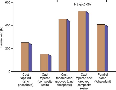
Fiber composite posts have increased in popularity. These posts consist of bundles of stretched aligned glass or carbon fibers* embedded in a resin matrix. The resulting post is strong but has significantly less stiffness and strength than do ceramic and metal posts.64 Preliminary retrospective study of the carbon fiber system appears promising65 (Fig. 12-30). However, in a laboratory study in which teeth restored with carbon fiber posts and composite-resin foundations were compared with teeth restored with custom post and cores cast in type III alloy, there were significantly higher fracture thresholds for the cast post and cores.66 One advantage of a fiber composite posts is their ease of its removal for re-treatment. The preferred technique involves drilling in an apical direction. The very strong carbon fibers prevent the drill from tracking laterally, avoiding penetration of the dentin and preventing the post from shattering easily into small fragments (Fig. 12-31).
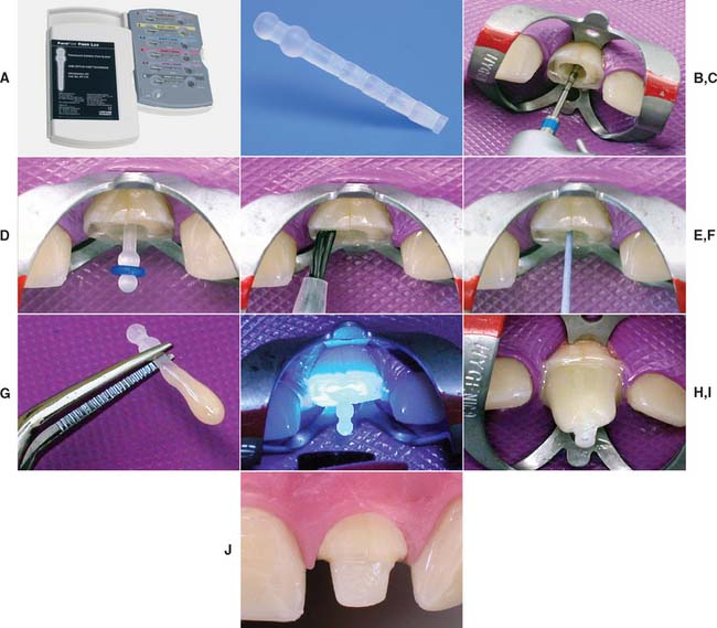
Fig. 12-30 Fiber composite posts. A and B, The ParaPost Fiber Lux system is available in various sizes. C, Gutta-percha is removed with hot instruments or a Gates Glidden drill. The canal is prepared sequentially with the drills provided by the manufacturer. D, The post is seated in the canal. E, The canal is prepared by etching and priming according to the manufacturer’s recommendations. F, The luting resin is introduced into the canal with a paper point. G, The post is coated with resin luting agent, seated and the resin polymerized (H). The translucent post allows light transmission to the luting agent. I, The core is built up with the recommended core resin. J, The preparation is finalized.
(Courtesy of Coltène/Whaledent AG, Altstatten, Switzerland.)
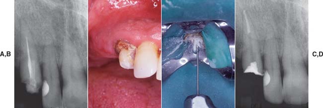
Fig. 12-31 A, Maxillary canine requires fiber post removal for endodontic re-treatment B, Composite resin core is removed first. C, Gates Glidden drill used to remove the fiber post. D, Endodontically re-treated tooth before fabrication of new post and core and extracoronal restoration. If concern exists about the long-term prognosis of an endodontically treated tooth, a carbon fiber post should be considered. The chief disadvantage of a carbon fiber post is its black appearance, which presents an esthetic problem (as can metal posts).
(Courtesy Dr. D.A. Miller.)
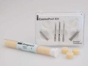
Manufacturers have developed high-strength ceramic67,68 (zirconia) posts† (Fig. 12-32) and ceramic composite‡ (Fig. 12-33) and woven fiber (e.g., polyethylene) posts,§ all of which have excellent esthetic properties (see also Chapters 25 and 27). Ceramic is very strong and rigid; woven fiber is less strong and more flexible.69 Because the systems are relatively new, judging how well the foundations will perform in clinical practice is difficult, but they should be considered when esthetic demands are high.
Corrosion resistance
Several reports70-72 have linked root fracture to corrosion of base metal prefabricated post and core systems. In one study,67 a report on 468 teeth with vertical or oblique root fracture, investigators attributed 72% of these failures to electrolytic action of dissimilar metals used for the post and the core (reaction occurring between tin in the amalgam core and stainless steel, German silver, or brass in the post). The authors suggested that volume changes produced by corrosion products split the root. Although possible fracture mechanisms have been suggested,68,69 these studies are confusing cause with effect: The corrosion may have occurred after root fracture rather than causing it.
Further study is needed to answer the question conclusively. However, in the meantime, avoiding the use of potentially corrodible dissimilar metals for post, core, and crown is recommended.
Custom-made posts
A custom-made cast post and core can be cast from a direct pattern fabricated in the patient’s mouth, or an indirect pattern can be fabricated in the dental laboratory. A direct technique with autopolymerizing or light-polymerized resin is recommended for single canals with good clinical access, whereas an indirect procedure is more appropriate for multiple canals or when access is more problematic. As an alternative to autopolymerizing resin, thermoplastic resin can be used.
Direct procedure
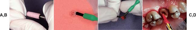
Fig. 12-34 A to D, Fabrication of an acrylic resin pattern for a custom-made post.
(Courtesy of Dr. R. Webber.)
The post pattern is complete when it can be inserted and removed easily without binding in the canal. Once the pattern has been made, additional resin or light-polymerized resin* is added for the core.
Pattern fabrication with thermoplastic resin. (Fig. 12-35)
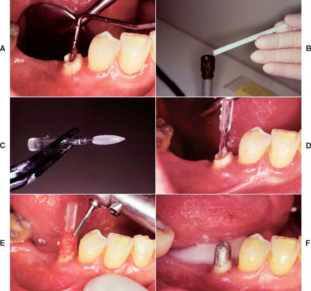
Fig. 12-35 The Merritt EZ Cast Post system. A, The canal is lubricated and excess lubricant removed with paper points. The post was previously trimmed until its beveled portion protruded about 1.5 to 2 mm above the tooth preparation. B, A stick of the thermoplastic material is heated. C, The plastic rod is covered for about two thirds of the anticipated post length. D, The coated post is inserted and can be removed in 5 to 10 seconds. E, After any protrusions have been removed, the core is built from autopolymerizing resin and trimmed to ideal tooth preparation form. F, The completed custom post and core.
(From Rosenstiel SF, et al: Custom-cast post fabrication with a thermoplastic material. J Prosthet Dent 77:209, 1997.)
Indirect procedure
Any elastomeric material will make an accurate impression of the root canal (Fig. 12-36A) if a wire reinforcement is placed to prevent distortion.
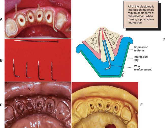
Access for waxing is generally adequate without placement of dowel pins or sectioning of the cast.
Core Fabrication
The core of a post and core restoration replaces missing coronal tooth structure and, combined with the remaining coronal tissue, forms the shape of the optimal tooth preparation. It can be shaped in resin or wax and added to the post pattern before the assembly is cast in one piece. It is cast directly onto a prefabricated post. Some concern arises that the casting process may unfavorably affect the physical properties of wrought metal posts. A third alternative is to make the core from a plastic restorative material, such as amalgam, or from composite resin or glass ionomer.
Plastic filling materials
The advantages of amalgam, glass ionomer, or resin62,73,74 include the following:
Disadvantages include the following:
Amalgam cores are suitable for restoring posterior teeth, particularly when some coronal structure remains. The procedure described by Nayyar and associates,45 with amalgam also used for the posts, is conservative of tooth structure. The cores are placed during the same appointment as the root canal obturation, because then the teeth are still isolated by the rubber dam, the practitioner is still familiar with the root canal structure, and the cores can serve as a support for the interim restoration (Fig. 12-38).
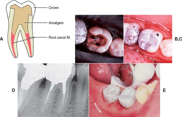
Fig. 12-38 A to E, Retention for an amalgam core can be obtained from the root canal system, preserving as much tooth structure as possible.
(B to D, Courtesy Dr. M. Padilla.)
Step-by-step procedure for amalgam (see also Chapter 6)
Cast metal
Cast metal cores have the following advantages:
Direct procedure for single-root teeth
Direct patterns can be formed by combining a prefabricated post with autopolymerizing resin. Alternatively, a thermoplastic material can be used to create a post pattern,80 and the core portion can be developed in autopolymerizing resin, light polymerized resin, or wax.
Pattern fabrication with autopolymerizing resin
Direct pattern for multiroot teeth
A direct pattern (Fig. 12-40) can be used for multiroot posterior teeth, although limited access may make the indirect approach easier. A single-piece core with auxiliary posts is used, as opposed to the multisection core recommended for indirect posterior cast post and cores. The core is cast directly onto the post of one canal. (The other canals already have prefabricated posts that pass through holes in the core.)
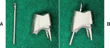
Fig. 12-40 A direct post and core for posterior teeth can be made by cementing a prefabricated post through a casting. Here the two buccal canals (A and B) had a common path of withdrawal and could be incorporated into the core casting. More typically, only one canal has a fixed post, and the others are cemented through the core.
The procedure is simple, as long as smooth parallel-sided or tapered posts are used:
Indirect pattern for posterior teeth (Fig. 12-41)
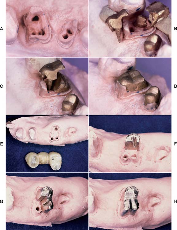
Fig. 12-41 A to D, Multipiece post and cores can be made by the indirect technique, waxing each section to ensure that no undercuts are created. E to H, Alternatively, interlocking sections can be made, but this complicates the laboratory phase.
Using dovetails to interlock the sections makes the procedure more complicated and is probably of limited benefit, especially because the final buildup is held together by the fixed cast restoration.
Interim Restorations (see Chapter 15)
To reduce the need for endodontic re-treatment, endodontically treated teeth should be restored as soon as practical after completion of the endodontic procedure. Zinc oxide–eugenol (ZOE) luting materials have been used for many years to achieve a seal before initiation of prosthetic treatment, However, such ZOE materials have been shown to leak at the dentin-material interface.83
Thus, if definitive restoration of the tooth is delayed, it is appropriate to etch and seal the access cavity with an adhesive resin to reduce the risk of microleakage. However, teeth in the esthetic zone often require a well-adapted interim restoration.
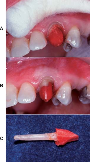
Such interim restorations prevent drifting of the tooth itself and of opposing or adjacent teeth after completion of endodontics (Fig. 12-42). Of particular importance are good proximal contacts to prevent tooth migration that leads to unwanted root proximity. If a cast post and core is made, the tooth will require an interim restoration while the post and core is being fabricated. This can be retained by fitting a wire (e.g., a paper clip or orthodontic wire) into the prepared canal. The restoration is then conveniently fabricated with autopolymerizing resin by the direct technique.
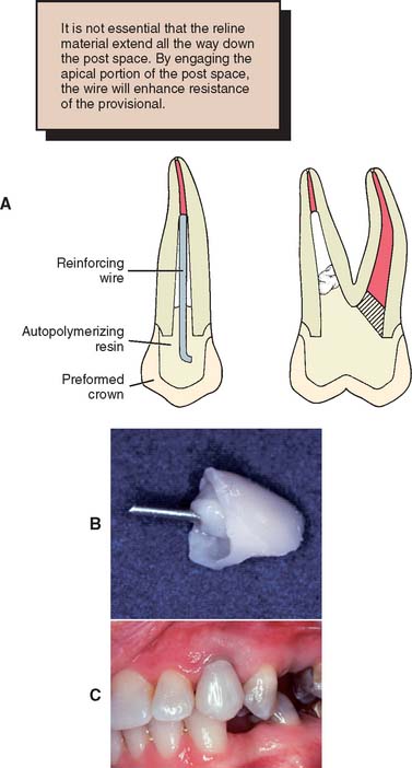
Fig. 12-42 A to C, Interim restorations made for endodontically treated teeth by lining a polycarbonate crown with autopolymerizing resin. The post is made of metal wire (orthodontic wire or a paper clip; see Chapter 15).
(A, From Taylor GN, Land MF: Restoring the endodontically treated tooth and the cast dowel. In Clark JW, ed: Clinical Dentistry, vol 4. New York, Harper & Row, 1985.)
Investing and Casting
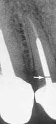
A cast post and core should fit somewhat loosely in the canal. A tight fit may cause root fracture. The casting should be slightly undersized, which can be accomplished by restricting expansion of the investment (i.e., by omitting the usual ring liner or casting at a lower mold temperature [see Chapter 22]). An accelerated casting technique may facilitate the laboratory phase.83 The casting alloy should have suitable physical properties. Extra-hard partial dental prosthetic gold (American Dental Association type IV) or Ni-Cr alloys have high moduli of elasticity and are suitable for cast posts (see Chapter 19). A sound casting technique is essential because any undetected porosity could lead to a weakened casting that might fail in function (Fig. 12-43).
Casting a core onto a prefabricated post avoids such problems of porosity, but the preheating temperature of the investment mold should be restricted if recrystallization of the wrought post84 is to be avoided. The latter would adversely affect its physical properties.
Evaluation
The practitioner must be particularly careful that casting defects do not interfere with seating of thepost; otherwise, root fracture will result. Post and cores should be inserted with gentle pressure. However, the marginal fit of a cast foundation is not as crucial as that of other cast restorations, because the margins will be covered by the final casting. Air-abrading the surface to a matte finish may help detect interferences at try-in (Fig. 12-44).
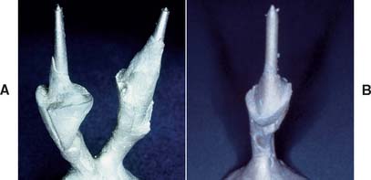
Fig. 12-44 A, The fitting surface of the casting must be carefully evaluated. B, Nodules, as can be seen here, could easily lead to root fracture and tooth loss.
The shape of the foundation is evaluated and adjusted as necessary.
Cementation
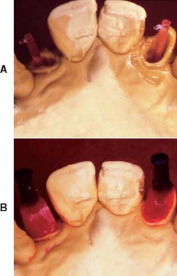
The luting agent must fill all dead space within the root canal system (Fig. 12-45). Voids may be a cause of periodontal inflammation via the lateral canals.
A rotary (lentulo) paste filler or cement tube (Fig. 12-46) is used to fill the canal with cement. The post and core is inserted gently to reduce hydrostatic pressure, which could cause root fracture. If a parallel-sided post is being used, a groove should be placed along the side of the post to allow for improved escape of excess cement. Use of venting procedures has also been shown to reduce the necessary seating force, although the latter is probably cement specific.85
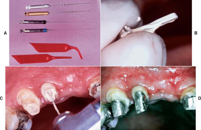
Fig. 12-46 A, Lentulo rotary paste fillers or a cement tube are used to fill the post space completely. B, The post is first coated with cement. C, The canal is filled with cement. D, To avoid the risk of fracture, the post and core is very gently seated. A small cement line is not usually significant, because dissolution is prevented by the presence of the definitive restoration.
(B to D, Courtesy of Dr. M. Padilla.)
Removal of Existing Posts
On occasion, an existing post and core must be removed (e.g., for re-treatment of a failed root canal filling). Patients must understand in advance that post removal is a risky process and occasionally results in radicular fracture. If sufficient length of post is exposed coronally, the post can be retrieved with thin-beaked forceps. Vibrating the post first with an ultrasonic scaler weakens brittle cement and facilitates removal. A thin scaler tip or special post removal tip is recommended (Fig. 12-47). Although histologic examination with animal models reveals no harmful effect in the periodontal tissues,86 ultrasonic removal is slower than other methods and may result in an increased number of canal and intradentin cracks.87 Alternatively, a post puller can be used.88 This device consists of a vise to grip the post and legs that bear on the root face. A screw activates the vise and extracts the post.
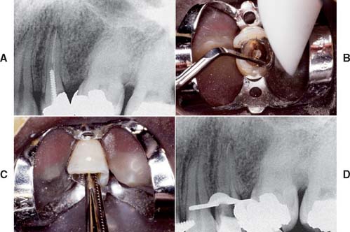
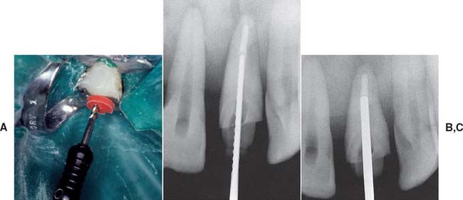
Fig. 12-47 Post removal by ultrasonic device. A, Preoperative radiograph of the left maxillary first premolar with a parallel-sided threaded post that had to be removed for endodontic retreatment. B, After the coronal portion of the post has been well isolated, the tip of the ultrasonic device is placed against it, and energy is applied to disrupt the cement interface. Note the suction tip, which removes water spray used with the ultrasonic handpiece. C, After a time, the post becomes loose within the canal and can be retrieved by forceps. D, Radiograph of the premolar after post removal.
(Courtesy of Dr. L. L. Lazare.)
A post that has fractured within the root canal cannot be removed with a post puller or forceps. The post can be drilled out, but great care is needed to avoid perforation. The technique is best limited to relatively short fractured posts (Fig. 12-48).
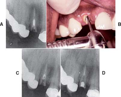
Fig. 12-48 Post removal by high-speed bur. A, Preoperative radiograph of the right maxillary lateral incisor, in which both the crown and part of a post have been fractured off. A portion of the Kurer-type, parallel-sided, threaded post remains within the canal. B, Because of the large diameter of the post and its position within the canal, a high-speed handpiece was chosen to drill it out. C, Radiograph to verify the correct orientation of the bur’s progress inside the canal. With this method of post removal, the operator must be extremely careful not to let the high-speed bur contact the canal wall, which would seriously compromise tooth structure. D, Radiograph of the incisor after post removal and re-treatment.
(Courtesy of Dr. D. A. Miller.)
Another means of handling an embedded fractured post (described by Masserann89 in 1966) is to use special hollow end-cutting tubes (or trephines) to prepare a thin trench around the post (Fig. 12-49). This technique has shown success.90 Retrieval can be facilitated by using an adhesive to attach a hollow tube extractor91 or by using a threaded extractor92 (Fig. 12-50).
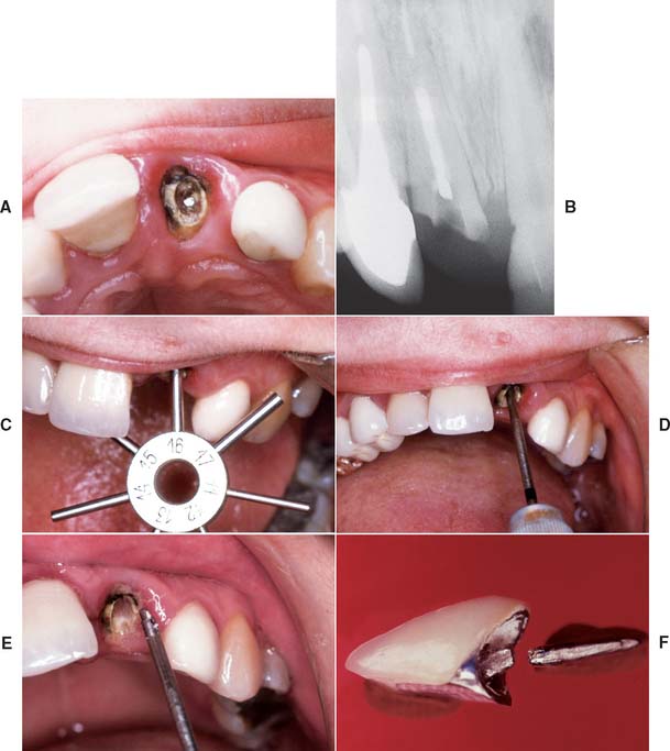
Fig. 12-49 Masserann technique for the removal of fractured posts. A and B, Maxillary incisor with a post that has fractured inside the canal. C, The diameter of the post is gauged with a sizing tool. D, The selected trephine is carefully rotated counterclockwise to create a narrow channel around the post. E, When the instrument has removed sufficient material, the post is recovered. F, The fractured crown and post after removal.
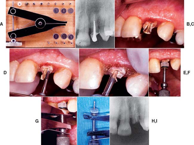
Fig. 12-50 Post removal by extractor. A, The Thomas (Gonon) post-removing system. It includes pliers, trephine burs, mandrels, and washers. B, Preoperative radiograph of the left maxillary lateral incisor with a post. C, Note the flared shape of the post in this preoperative view and the height of the surrounding tooth structure. D, A high-speed bur is used to free the post from coronal tooth structure and parallel its sides. (Note: An ultrasonic device may be used at this point to disturb the cement interface.) E, A trephine bur machines the post to the correct diameter and places threads for the mandrel. F, The mandrel is threaded onto the post with special washers, which distribute the forces from the extractor evenly over the tooth. G, The beaks of the pliers are fitted onto the mandrel; the knob of the pliers is then rotated, which separates the beaks, and the post is extruded from the tooth. H, The removed post, still attached to the mandrel and pliers. I, Radiograph of the lateral incisor after post removal.
(Courtesy of Dr. D. A. Miller.)
SUMMARY
Although the restoration of endodontically treated teeth has been rationalized considerably by laboratory research data, information from controlled long-term clinical trials is still necessary and difficult to obtain. Different clinical procedures have been advocated, many of which are successful if properly used. Where the crown is preserved and circumferentially largely intact, an anterior tooth can be safely restored with a plastic filling. To prevent fracture of posterior teeth, cast restorations providing cuspal coverage are recommended.
Preserving as much tooth structure as possible is important, particularly within the root canal, in which the amount of remaining dentin may be difficult to assess.
A post and core is used to provide retention and support for a cast restoration. It should be of adequate length for good stress distribution but not so long that it jeopardizes the apical seal. The safest method to create post space is to use a heated endodontic plugger to remove the gutta-percha. Anterior teeth, particularly those with flared or elliptical canals, should be built up with a custom cast post and core, which offers great strength, although prefabricated posts can be used successfully when adequate retention and resistance form for the plastic material can be obtained. Esthetic post materials should be considered if a dark post would prevent fabrication of an esthetic restoration. Amalgam core material can be used satisfactorily on posterior teeth when one or more cusps have been lost, although a casting may be preferred if substantial coronal tooth structure is missing.
 GLOSSARY*
anatomic crown \ăn′a-t m′
m′ k kroun\: the portion of a natural tooth that extends coronal from the cementoenamel junction—called also anatomical crown
a·nu·lar \ăn′ya-ler\ n (1571): a term used to describe a ring like anatomic structure
apex \ā′p ks′\ n, pl apex·es or api·ces (1601): 1: the uppermost point; the vertex 2: in dentistry, the anatomic end of a tooth root
autopolymerizing resin \ô′tō-pl-a-mr-ī′zing rz′n\: a resin whose polymerization is initiated by a chemical activator
avul·sion \a-vŭl′shun\ n (1622): a forcible separation or detachment, as in a tearing away of a body part surgically or accidentally
dow·el \dou′al\ n, obs (13c): a post usually made of metal that is fitted into a prepared root canal of a natural tooth. When combined with an artificial crown or core, it provides retention and resistance for the restoration—See POST
e·las·tic \-lăs′tk\ adj (1653): susceptible to being stretched, compressed, or distorted and then tending to resume the original shape
elastic modulus \-lăs′tk mj′a-lus\: the stiffness or flexibility of a material within the elastic range. Within the elastic range, the material deforms in direct proportion to the stress applied as represented by Hooke’s law
ex·po·sure \k-spō′zher\ n (1606): 1: the act of laying open, as a surgical or dental exposure 2: in radiology, a measure of the roentgen rays or gamma radiation at a certain place based on its ability to cause ionization. The unit of exposure is the roentgen, called also exposure dose—see ROENTGEN RAY
fer·rule \fr′al\ n (15c): 1: a metal band or ring used to fit the root or crown of a tooth 2: any short tube or bushing for making a tight joint
mo·o·mer \mn′a-mar\ n (1914): a chemical compound that can undergo polymerization; any molecule that can be bound to a similar molecule to form a polymer
polymerization \pa-l′ar-ī-zā′shun\ n (1872): the forming of a compound by the joining together of molecules of small molecular weights into a compound of large molecular weight
rad·ic·u·lar \ră-d-kyōō′lar\ adj (1830): pertaining to the root of a tooth
res·in \rz′n\ n (14c): 1: any of various solid or semisolid amorphous natural organic substances that usually are transparent or translucent and brown to yellow; usually formed in plant secretions; are soluble in organic solvents but not water; are used chiefly in varnishes, inks, plastics, and medicine; and are found in many dental impression materials 2: a broad term used to describe natural or synthetic substances that form plastic materials after polymerization. They are named according to their chemical composition, physical structure, and means for activation of polymerization—see AUTOPOLYMERIZING R., COPOLYMER R.
root \rōōt, r
t\ n (bef. 12c): the portion of the tooth apical to the cementoenamel junction that is normally covered by cementum and is attached to the periodontal ligament and hence to the supporting bone
stress \strs\ n (14c): force per unit area; a force exerted on one body that presses on, pulls on, pushes against, or tends to invest or compress another body; the deformation caused in a body by such a force; an internal force that resists an externally applied load or force. It is normally defined in terms of mechanical stress, which is the force divided by the perpendicular cross sectional area over which the force is applied—see COMPRESSIVE S., SHEARING S., TENSILE S.
wax pattern \wăks păt′urn\: a wax form that is the positive likeness of an object to be fabricated
STUDY QUESTIONS
1 Johnson JK, et al. Evaluation and restoration of endodontically treated posterior teeth. J Am Dent Assoc. 1976;93:597.
2 Kakehashi Y, et al. A new all-ceramic post and core system: clinical, technical, and in vitro results. Int J Periodontics Restorative Dent. 1998;18:586.
3 Blitz N. Adaptation of a fiber-reinforced restorative system to the rehabilitation of endodontically treated teeth. Pract Periodont Aesthet Dent. 1998;10:191.
4 Torbjörner A, et al. Survival rate and failure characteristics for two post designs. J Prosthet Dent. 1995;73:439.
5 Sorensen JA, Martinoff JT. Clinically significant factors in dowel design. J Prosthet Dent. 1984;52:28.
6 Loney RW, et al. The effect of load angulation on fracture resistance of teeth restored with cast post and cores and crowns. Int J Prosthodont. 1995;8:247.
7 Helfer AR, et al. Determination of the moisture content of vital and pulpless teeth. Oral Surg Oral Med Oral Pathol. 1972;34:661.
8 Trabert KC, et al. Tooth fracture: a comparison of endodontic and restorative treatments. J Endodont. 1978;4:341.
9 Guzy GE, Nicholls JI. In vitro comparison of intact endodontically treated teeth with and without endo-post reinforcement. J Prosthet Dent. 1979;42:39.
10 Hunter AJ, et al. Effects of post placement on endodontically treated teeth. J Prosthet Dent. 1989;62:166.
11 Ko CC, et al. Effects of posts on dentin stress distribution in pulpless teeth. J Prosthet Dent. 1992;68:421.
12 Kantor ME, Pines MS. A comparative study of restorative techniques for pulpless teeth. J Prosthet Dent. 1977;38:405.
13 Sorensen JA, Martinoff JT. Intracoronal reinforcement and coronal coverage: a study of endodontically treated teeth. J Prosthet Dent. 1984;51:780.
14 Lu YC. A comparative study of fracture resistance of pulpless teeth. Chin Dent J. 1987;6:26.
15 Aquilino SA, Caplan DJ. Relationship between crown placement and the survival of endodontically treated teeth. J Prosthet Dent. 2002;87:256.
16 Warren MA, et al. In vitro comparison of bleaching agents on the crowns and roots of discolored teeth. J Endodont. 1990;16:463.
17 Madison S, Walton R. Cervical root resorption following bleaching of endodontically treated teeth. J Endodont. 1990;16:570.
18 Hansen EK, et al. In vivo fractures of endodontically treated posterior teeth restored with amalgam. Endod Dent Traumatol. 1990;6:49.
19 McKerracher PW. Rational restoration of endodontically treated teeth. I. Principles, techniques, and materials. Aust Dent J. 1981;26:205.
20 Felton DA, et al. Threaded endodontic dowels: effect of post design on incidence of root fracture. J Prosthet Dent. 1991;65:179.
21 Henry PJ. Photoelastic analysis of post core restorations. Aust Dent J. 1977;22:157.
22 Assif DF, et al. Photoelastic analysis of stress transfer by endodontically treated teeth to the supporting structure using different restorative techniques. J Prosthet Dent. 1989;61:535.
23 Milot P, Stein RS. Root fracture in endodontically treated teeth related to post selection and crown design. J Prosthet Dent. 1992;68:428.
24 Sorensen JA, Engelman MJ. Ferrule design and fracture resistance of endodontically treated teeth. J Prosthet Dent. 1990;63:529.
25 Libman WJ, Nicholls JI. Load fatigue of teeth restored with cast posts and cores and complete crowns. Int J Prosthodont. 1995;8:155.
26 Isidor F, et al. The influence of post length and crown ferrule length on the resistance to cyclic loading of bovine teeth with prefabricated titanium posts. Int J Prosthodont. 1999;12:78.
27 Gegauff AG. Effect of crown lengthening and ferrule placement on static load failure of cemented cast post-cores and crowns. J Prosthet Dent. 2000;84:169.
28 Turner CH. Post-retained crown failure: a survey. Dent Update. 1982;9:221.
29 Standlee JP, et al. Retention of endodontic dowels: effects of cement, dowel length, diameter, and design. J Prosthet Dent. 1978;39:401.
30 Ruemping DR, et al. Retention of dowels subjected to tensile and torsional forces. J Prosthet Dent. 1979;41:159.
31 Kurer HG, et al. Factors influencing the retention of dowels. J Prosthet Dent. 1977;38:515.
32 Cooney JP, et al. Retention and stress distribution of tapered-end endodontic posts. J Prosthet Dent. 1986;55:540.
33 Krupp JD, et al. Dowel retention with glass-ionomer cement. J Prosthet Dent. 1979;41:163.
34 Wood WW. Retention of posts in teeth with nonvital pulps. J Prosthet Dent. 1983;49:504.
35 Hanson EC, Caputo AA. Cementing mediums and retentive characteristics of dowels. J Prosthet Dent. 1974;32:551.
36 Chapman KW, et al. Retention of prefabricated posts by cements and resins. J Prosthet Dent. 1985;54:649.
37 Driessen CH, et al. The effect of bonded and nonbonded posts on the fracture resistance of dentin. J Dent Assoc S Afr. 1997;52:393.
38 Mendoza DB, Eakle WS. Retention of posts cemented with various dentinal bonding cements. J Prosthet Dent. 1994;72:591.
39 O’Keefe KL, et al. In vitro bond strength of silica-coated metal posts in roots of teeth. Int J Prosthod. 1992;5:373.
40 Tjan AH, Nemetz H. Effect of eugenol-containing endodontic sealer on retention of prefabricated posts luted with adhesive composite resin cement. Quintessence Int. 1992;23:839.
41 Radke RA, et al. Retention of cast endodontic posts: comparison of cementing agents. J Prosthet Dent. 1988;59:318.
42 Love RM, Purton DG. Retention of posts with resin, glass ionomer and hybrid cements. J Dent. 1998;26:599.
43 Assif D, et al. Retention of endodontic posts with a composite resin luting agent: effect of cement thickness. Quintessence Int. 1988;19:643.
44 Kane JJ, et al. Fracture resistance of amalgam coronal-radicular restorations. J Prosthet Dent. 1990;63:607.
45 Nayyar A, et al. An amalgam coronal-radicular dowel and core technique for endodontically treated posterior teeth. J Prosthet Dent. 1980;43:511.
46 Mentink AG, et al. Qualitative assessment of stress distribution during insertion of endodontic posts in photoelastic material. J Dent. 1998;26:125.
47 Standlee JP, et al. The retentive and stress-distributing properties of a threaded endodontic dowel. J Prosthet Dent. 1980;44:398.
48 Thorsteinsson TS, et al. Stress analysis of four prefabricated posts. J Prosthet Dent. 1992;67:30.
49 Dérand T. The principal stress distribution in a root with a loaded post in model experiments. J Dent Res. 1977;56:1463.
50 Leary JM, et al. Load transfer of posts and cores to roots through cements. J Prosthet Dent. 1989;62:298.
51 Peters MCRB, et al. Stress analysis of a tooth restored with a post and core. J Dent Res. 1983;62:760.
52 Yaman SD, et al. Analysis of stress distribution in a maxillary central incisor subjected to various post and core applications. J Endodont. 1998;24:107.
53 Zmener O. Effect of dowel preparation on the apical seal of endodontically treated teeth. J Endodont. 1980;6:687.
54 Neagley RL. The effect of dowel preparation on the apical seal of endodontically treated teeth. Oral Surg Oral Med Oral Pathol. 1969;28:739.
55 Schnell FJ. Effect of immediate dowel space preparation on the apical seal of endodontically filled teeth. Oral Surg Oral Med Oral Pathol. 1978;45:470.
56 Bourgeois RS, Lemon RR. Dowel space preparation and apical leakage. J Endodont. 1981;7:66.
57 Gegauff AG, et al. A comparative study of post preparation diameters and deviations using ParaPost and Gates-Glidden drills. J Endodont. 1988;14:377.
58 Hussey DL, et al. Thermographic assessment of heat generated on the root surface during post space preparation. Int Endodont J. 1997;30:187.
59 Caputo AA, Standlee JP. Pins and posts: why, when, and how. Dent Clin North Am. 1976;20:299.
60 Shillingburg HT, et al. Root dimensions and dowel size. Calif Dent Assoc J. 1982;10(10):43.
61 Abou-Rass M, et al. Preparation of space for posting: effect on thickness of canal walls and incidence of perforation in molars. J Am Dent Assoc. 1982;104:834.
62 Perez Moll JF, et al. Cast gold post and core and pin-retained composite resin bases: a comparative study in strength. J Prosthet Dent. 1978;40:642.
63 Phillips RW. Skinner’s Science of Dental Materials, 9th ed., Philadelphia: WB Saunders; 1991:550.
64 Asmussen E, et al. Stiffness, elastic limit, and strength of newer types of endodontic posts. J Dent. 1999;27:275.
65 Frederiksson M, et al. A retrospective study of 236 patients with teeth restored by carbon fiber epoxy resin posts. J Prosthet Dent. 1998;80:151.
66 Martinez-Insua A, et al. Comparison of the fracture resistances of pulpless teeth restored with a cast post and core or carbon-fiber post with a composite core. J Prosthet Dent. 1998;80:527.
67 Kakehashi Y, et al. A new all-ceramic post and core system: clinical, technical, and in vitro results. Int J Periodontics Restorative Dent. 1998;18:586.
68 Ahmad I. Zirconium oxide post and core system for the restoration of an endodontically treated incisor. Pract Periodont Aesthet Dent. 1999;11:197.
69 Sirimai S, et al. An in vitro study of the fracture resistance and the incidence of vertical root fracture of pulpless teeth restored with six post-and-core systems. J Prosthet Dent. 1999;81:262.
70 Rud J, Omnell KA. Root fractures due to corrosion: diagnostic aspects. Scand J Dent Res. 1970;78:397.
71 Angmar-Manansson B, et al. Root fracture due to corrosion. I. Metallurgical aspects. Odontol Rev. 1969;20:245.
72 Silness J, et al. Distribution of corrosion products in teeth restored with metal crowns retained by stainless steel posts. Acta Odontol Scand. 1979;37:317.
73 Chan RW, Bryant RW. Post-core foundations for endodontically treated posterior teeth. J Prosthet Dent. 1982;48:401.
74 Lovdahl PE, Nicholls JI. Pin-retained amalgam cores vs. cast-gold dowel-cores. J Prosthet Dent. 1977;38:507.
75 Reagan SE, et al. Effects of cyclic loading on selected post-and-core systems. Quintessence Int. 1999;30:61.
76 Foley J, et al. Strength of core build-up materials in endodontically treated teeth. Am J Dent. 1997;10:166.
77 Kovarik RE, et al. Fatigue life of three core materials under simulated chewing conditions. J Prosthet Dent. 1992;68:584.
78 Oliva RA, Lowe JA. Dimensional stability of composite used as a core material. J Prosthet Dent. 1986;56:554.
79 Larson TD, Jensen JR. Microleakage of composite resin and amalgam core material under complete cast crowns. J Prosthet Dent. 1980;44:40.
80 Rosenstiel SF, et al. Custom-cast post fabrication with a thermoplastic material. J Prosthet Dent. 1997;77:209.
81 Waldmeier MD, Grasso JE. Light-cured resin for post patterns. J Prosthet Dent. 1992;68:412.
82 Zmener O, et al. Coronal microleakage of three temporary restorative materials: an in vitro study. J Endodont. 2004;30:582.
83 Campagni WV, Majchrowicz M. An accelerated technique for the casting of post and core restorations. J Prosthet Dent. 1991;66:155.
84 Brunell G. Casting and microstructure of post and core at different mold temperatures. Acta Odontol Scand. 1982;40:241.
85 Wilson PR. Low force cementation. J Dent. 1996;24:269.
86 Yoshida T, et al. An experimental study of the removal of cemented dowel-retained cast cores by ultrasonic vibration. J Endodont. 1997;23:239.
87 Altshul JH, et al. Comparison of dentinal crack incidence and of post removal time resulting from post removal by ultrasonic or mechanical force. J Endodont. 1997;23:683.
88 Warren SR, Gutmann JL. Simplified method for removing intraradicular posts. J Prosthet Dent. 1979;42:353.
89 Masserann J. The extraction of posts broken deeply in the roots. Actual Odontostomatol. 1966;75:329.
90 Williams VD, Bjorndal AM. The Masserann technique for the removal of fractured posts in endodontically treated teeth. J Prosthet Dent. 1983;49:46.
91 Gettleman BH, et al. Removal of canal obstructions with the Endo Extractor. J Endodont. 1991;17:608.
92 Machtou P, et al. Post removal prior to retreatment. J Endodont. 1989;15:552.