chapter 18

Bisecting Technique

Outline

BASIC CONCEPTS

Terminology

Principles of Bisecting Technique

Receptor Stabilization

Receptors Used in Bisecting Technique

Position-Indicating Device Angulation

Rules of Bisecting Technique

STEP-BY-STEP PROCEDURES

Patient Preparation

Equipment Preparation

Exposure Sequence for Receptor Placements

Receptor Placement for Bisecting Technique

ADVANTAGES AND DISADVANTAGES

Advantages of Bisecting Technique

Disadvantages of Bisecting Technique

Learning Objectives

After completion of this chapter, the student will be able to do the following:

• Define the key terms associated with the bisecting technique

• State the rule of isometry

• State the basic principles of the bisecting technique and illustrate the location of the receptor, tooth, imaginary bisector, central ray, and position-indicating device (PID)

• List the beam alignment devices that can be used with the bisecting technique

• Describe the receptor size used with the bisecting technique

• Describe the correct and incorrect horizontal angulation

• Describe correct and incorrect vertical angulation

• State each of the recommended vertical angulation ranges used for periapical exposures in the bisecting technique

• State the basic rules of the bisecting technique

• Describe patient and equipment preparations necessary before using the bisecting technique

• Discuss the exposure sequence used for the 14 periapical receptor placements used in the bisecting technique

• Describe each of the 14 periapical receptor placements recommended for use in the bisecting technique

• List the advantages and disadvantages of the bisecting technique

Key Terms

Angle

Angulation

Angulation, horizontal

Angulation, vertical

Beam alignment device

Bisect

Bisecting technique

Bisector, imaginary

Central ray

Elongation

Exposure sequence

Foreshortening

Hypotenuse

Isometry

Isometry, rule of

Long axis (tooth)

Receptor placement

Teeth, anterior

Teeth, posterior

Triangle

Triangle, equilateral

Triangle, right

Triangles, congruent

The dental radiographer must master a variety of intraoral imaging techniques. As discussed in Chapter 17, the paralleling technique is one method for exposing periapical and bite-wing images. Another intraoral method for exposing periapical images is the bisecting technique. Before the dental radiographer can use this technique, an understanding of the basic concepts, including terminology and principles, is necessary. In addition, the dental radiographer must comprehend patient preparation, equipment preparation, exposure sequencing, and receptor placement procedures used in the bisecting technique.

The purpose of this chapter is to present basic concepts and to describe patient preparation, equipment preparation, and receptor placement procedures used in the bisecting technique. This chapter also describes the advantages and disadvantages of the bisecting technique and reviews helpful hints.

Basic Concepts

The bisecting technique (also known as the bisecting-angle technique or bisection-of-the-angle technique) is another method that can be used to expose periapical images.

Terminology

An understanding of the following basic terms is necessary before describing the bisecting technique:

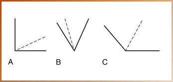
Angle: In geometry, a figure formed by two lines diverging from a common point (Figure 18-1, A).

image

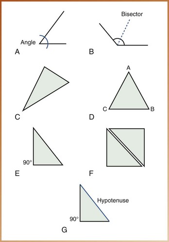
FIGURE 18-1 A, An angle is formed by two lines that diverge from a common point. B, A bisector divides an angle into equal angles. C, A triangle. D, An equilateral triangle has three equal sides (AB = BC = CA). E, A right triangle has one 90-degree angle. F, Congruent triangles are identical. G, The hypotenuse is the side of a right triangle opposite the right angle.

Bisect: To divide into two equal parts (noun, bisector) (Figure 18-1, B).

Triangle: In geometry, a figure formed by connecting three points not in a straight line by three straight-line segments (Figure 18-1, C). A triangle has three angles.

Triangle, equilateral: In geometry, a triangle with three equal sides (Figure 18-1, D).

Triangle, right: In geometry, a triangle with one 90-degree angle (right angle) (Figure 18-1, E).

Triangles, congruent: Triangles that are identical and correspond exactly when superimposed (Figure 18-1, F).

Hypotenuse: In geometry, the side of a right triangle opposite the right angle (Figure 18-1, G).

Isometry: Equality of measurement.

Long axis of the tooth: An imaginary line that divides the tooth longitudinally into two equal halves (Figure 18-2).

image

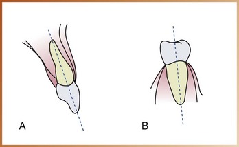
FIGURE 18-2 A, The long axis of the maxillary incisor divides the tooth into two equal halves. B, The long axis of a mandibular premolar divides the tooth into two equal halves.

Central ray: The central portion of the primary beam of x-radiation.

Principles of Bisecting Technique

The bisecting technique is based on a simple geometric principle known as the rule of isometry. The rule of isometry states that two triangles are equal if they have two equal angles and share a common side (Figure 18-3). In dental imaging, this geometric principle is applied to the bisecting technique to form two imaginary equal triangles (Figure 18-4). The bisecting technique can be described as follows:

image

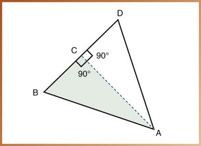
FIGURE 18-3 Angle A is bisected by line AC. Line AC is perpendicular to line BD. Angle BAC is equal to angle DAC. Angle ACB is equal to angle ACD. According to the rule of isometry, triangle BAC (shaded) is equal to triangle DAC.

image

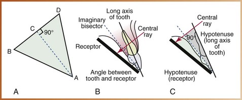
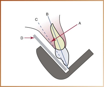
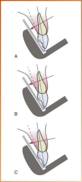
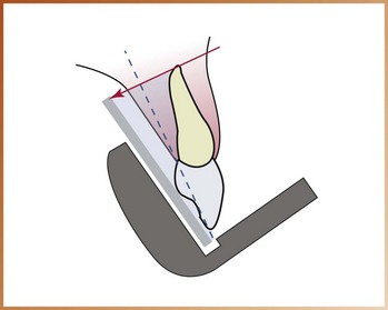
FIGURE 18-4 A, The receptor (line BA) is placed along the lingual surface of the tooth. At the point where the receptor contacts the tooth, the plane of the receptor and the long axis of the tooth (DA) form an angle (BAD). The imaginary bisector divides this angle into two equal angles (BAC and DAC). The central ray (BD) is directed perpendicular to the imaginary bisector and completes the third sides (BC and CD) of the two triangles. B, The central ray is directed at a right angle to the imaginary bisector. C, The two imaginary triangles that result are right triangles and congruent. The hypotenuse of each triangle is represented by the long axis of the tooth and the plane of the receptor.

1. The receptor must be placed along the lingual surface of the tooth.

2. At the point where the receptor contacts the tooth, the plane of the receptor and the long axis of the tooth form an angle.

3. The dental radiographer must visualize a plane that divides in half, or bisects, the angle formed by the receptor and the long axis of the tooth. This plane is termed the imaginary bisector. The imaginary bisector creates two equal angles and provides a common side for the two imaginary equal triangles.

4. The dental radiographer must then direct the central ray of the x-ray beam perpendicular to the imaginary bisector. When the central ray is directed at an angle of 90 degrees to the imaginary bisector, two imaginary equal triangles are formed.

5. The two imaginary triangles that result are right triangles and are congruent. The hypotenuse of one imaginary triangle is represented by the long axis of the tooth; the other hypotenuse is represented by the plane of the receptor.

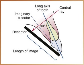
When the rule of isometry is followed strictly, the dental image of the tooth will be accurate. When the angle formed by the plane of the receptor and the long axis of the tooth is bisected, and the x-ray beam is directed at a right angle to the imaginary bisector, the actual tooth and the dental image of the tooth will be of the same length (Figure 18-5).

image

FIGURE 18-5 The image on the receptor is equal to the length of the tooth when the central ray is directed at 90 degrees to the imaginary bisector. A tooth and its image will be equal in length when two equal triangles are formed that share a common side (imaginary bisector).

Receptor Stabilization

In the bisecting technique, beam alignment devices may be used to position and stabilize the receptor.

Beam Alignment Devices

Beam alignment devices are used to position an intraoral receptor in the mouth and maintain it in position during exposure (see Chapter 6). Examples of commercially available intraoral beam alignment devices that can be used with the bisecting technique include the following:

• Rinn BAI instruments (Dentsply, Rinn Corporation, Elgin, IL). The bisecting angle instrument (BAI) includes plastic bite-blocks, plastic aiming rings, and metal indicator arms. To reduce the amount of radiation received by the patient, snap-on ring collimators can be added to the plastic aiming rings. BAIs have been designed to aid in the determination of horizontal and vertical angulations, minimize distortion from film bending, and prevent cone-cuts (Figure 18-6, A).

image

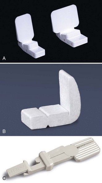
FIGURE 18-6 A, Rinn bisecting angle bite-blocks used with the bisecting technique. B, Stabe disposable film holders (bite-blocks). C, EEZEE-Grip (Snap-A-Ray) intraoral receptor holder.

• Stabe bite-block (Rinn). This device can be used with the paralleling technique or the bisecting technique. For use with the bisecting technique, the scored front section is removed, and the receptor is placed as close to the teeth as possible (Figure 18-6, B).

• EEZEE-Grip receptor holder (Rinn). Formerly known as Snap-A-Ray, this device is used to stabilize a receptor in either the paralleling technique or the bisecting technique (Figure 18-6, C).

The Stabe bite-block is disposable and is designed for one-time use only. BAIs and the EEZEE-Grip film holder are reusable and must be sterilized after each use.

BAIs with collimators are the recommended devices for the bisecting technique because (1) aiming rings are included that aid in the alignment of the position-indicating device (PID), and (2) collimators significantly reduce the amount of patient exposure to x-radiation. BAIs are simple to assemble and position. For information about the use of BAIs or other devices available for the bisecting technique, the dental radiographer should refer to the manufacturer’s instructions.

Receptors Used in Bisecting Technique

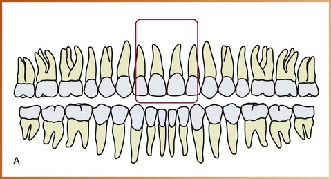
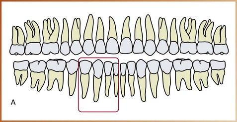
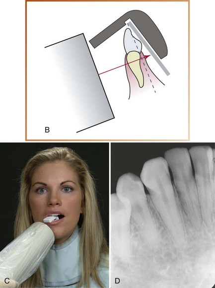
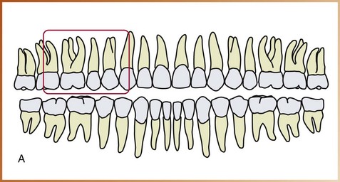
Traditionally, a size 2 intraoral receptor is used with the bisecting technique. In the anterior regions, a size 2 receptor is always placed with the long portion of the receptor in a vertical (upright) direction. In the posterior regions, a size 2 receptor is always placed with the long portion of the receptor in a horizontal (sideways) direction.

Position-Indicating Device Angulation

In the bisecting technique, the angulation of the PID is critical. Angulation is a term used to describe the alignment of the central ray of the x-ray beam in horizontal and vertical planes. Angulation can be varied by moving the PID in either a horizontal direction or a vertical direction. The use of BAIs with aiming rings dictates the proper PID angulation. However, when a bite-block or other device without an aiming ring is employed, the dental radiographer must determine both horizontal and vertical angulations.

Horizontal Angulation

Horizontal angulation refers to the positioning of the PID and the direction of the central ray in a horizontal, or side-to-side, plane (Figure 18-7). The horizontal angulation does not differ according to the technique used; paralleling, bisecting, and bite-wing techniques all use the same principles of horizontal angulation.

image

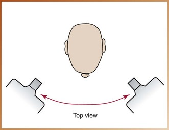
FIGURE 18-7 Horizontal angulation of the position-indicating device (PID) refers to PID placement in a side-to-side (ear-to-ear) direction. (From Haring JI, Lind LJ: Radiographic interpretation for the dental hygienist, Philadelphia, 1993, Saunders.)

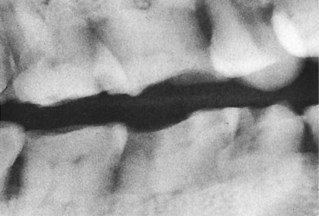
Correct Horizontal Angulation: With correct horizontal angulation, the central ray is directed perpendicular to the curvature of the arch and through the contact areas of the teeth (Figure 18-8). As a result, the contact areas on the dental image appear “opened.”

image

FIGURE 18-8 Correct horizontal angulation.

Incorrect Horizontal Angulation: Incorrect horizontal angulation results in overlapped (“unopened”) contact areas (Figure 18-9). An image with overlapped interproximal contact areas cannot be used to examine the interproximal areas of the teeth and is thus nondiagnostic (Figure 18-10).

image

FIGURE 18-9 Incorrect horizontal angulation.

image

FIGURE 18-10 Overlapped contacts. (From Haring JI, Lind LJ: Radiographic interpretation for the dental hygienist, Philadelphia, 1993, Saunders.)

Vertical Angulation

Vertical angulation refers to the positioning of the PID in a vertical, or up-and-down, plane (Figure 18-11). Vertical angulation is measured in degrees and is registered on the outside of the tubehead. The vertical angulation differs according to the imaging technique used, as follows:

image

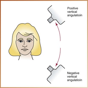
FIGURE 18-11 Vertical angulation of the position-indicating device (PID) refers to PID placement in an up-and-down (head-to-toe) direction. (From Haring JI, Lind LJ: Radiographic interpretation for the dental hygienist, Philadelphia, 1993, Saunders.)

• With the paralleling technique, the vertical angulation of the central ray is directed perpendicular to the receptor and the long axis of the tooth (see Chapter 17).

• With the bisecting technique, the vertical angulation is determined by the imaginary bisector; the central ray is directed perpendicular to the imaginary bisector.

• With the bite-wing technique, the vertical angulation is predetermined; the central ray is directed at +10 degrees to the occlusal plane (see Chapter 19).

Correct Vertical Angulation: Correct vertical angulation results in a dental image that is of the same length as that of the tooth. Table 18-1 lists recommended vertical angulation ranges for the bisecting technique.

TABLE 18-1

Recommended Vertical Angulation Ranges: Bisecting Technique

  Maxillary Teeth: Vertical Angulation (degrees) Mandibular Teeth: Vertical Angulation (degrees)
Canines +45 to +55 −20 to −30
Incisors +40 to +50 −15 to −25
Premolars +30 to +40 −10 to −15
Molars +20 to +30 −5 to 0

Incorrect Vertical Angulation: Incorrect vertical angulation results in a radiographic image that is not of the same length as that of the tooth; instead, the image appears longer or shorter. Elongated or foreshortened images are not diagnostic.

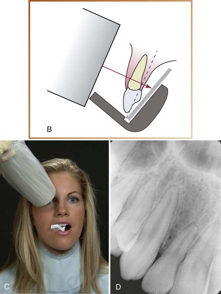
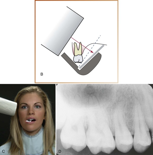
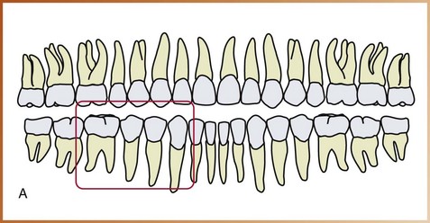
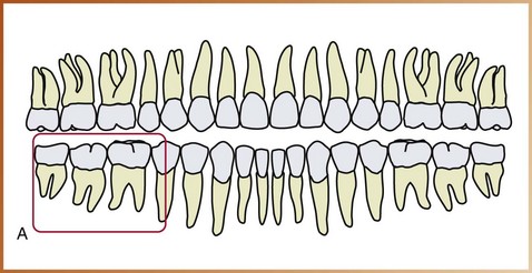
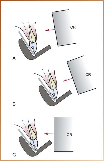
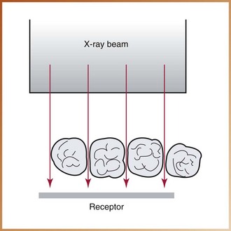
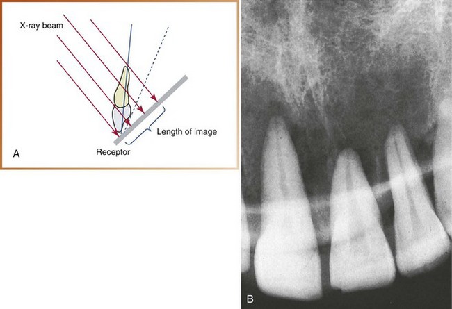
Foreshortened Images: Foreshortened images refer to radiographic images that appear shortened. Foreshortening of images results from excessive vertical angulation. When the vertical angulation is too steep, the image of the tooth appears shorter than the actual tooth (Figure 18-12). Foreshortening also occurs if the central ray is directed perpendicular to the plane of the receptor rather than to the imaginary bisector.

image

FIGURE 18-12 A, If the vertical angulation is too steep, the image is shorter than the actual tooth. B, Foreshortened images. (From Haring JI, Lind LJ: Radiographic interpretation for the dental hygienist, Philadelphia, 1993, Saunders.)

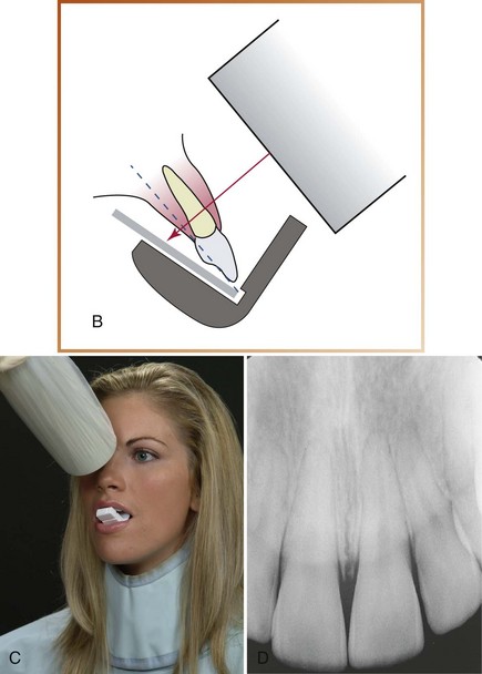
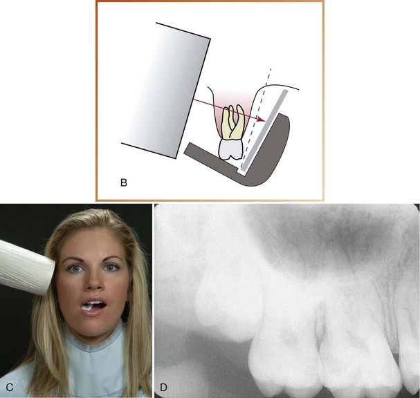
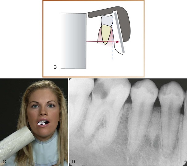
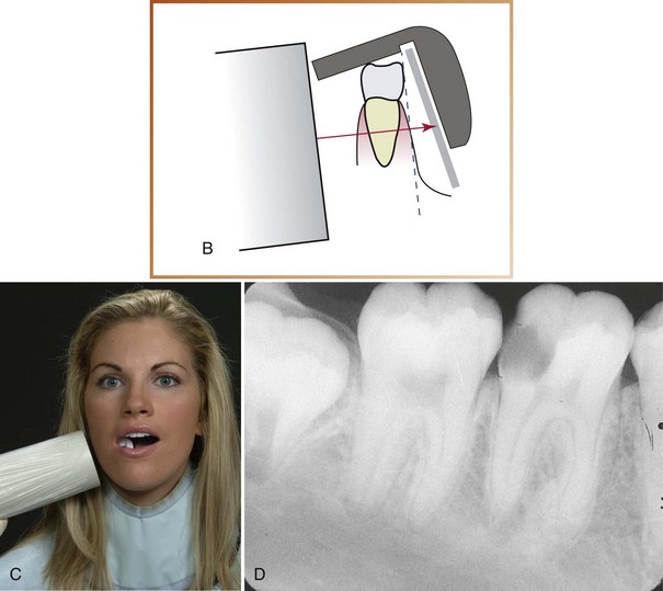
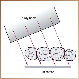
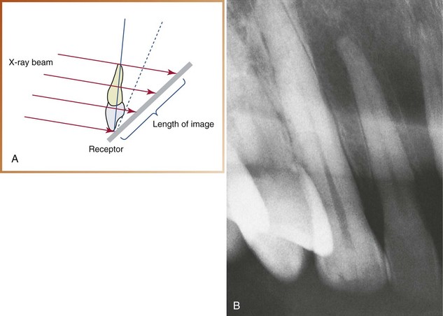
Elongated Images: Elongated images refer to images of the teeth that appear too long. Elongation of images results from insufficient vertical angulation. When the vertical angulation is too flat, the image of the tooth appears longer than the actual tooth (Figure 18-13). Elongation also occurs if the central ray is directed perpendicular to the long axis of the tooth rather than to the imaginary bisector.

image

FIGURE 18-13 A, If the vertical angulation is too flat, the image is longer than the actual tooth. B, Elongated images. (From Haring JI, Lind LJ: Radiographic interpretation for the dental hygienist, Philadelphia, 1993, Saunders.)

Rules of Bisecting Technique

Five basic rules should be followed when using the bisecting technique.

1. Receptor placement. The receptor must be positioned to cover the prescribed area of the tooth to be examined. Specific placements are described in the procedures.

2. Receptor position. The receptor must be placed against the lingual surface of the tooth. The occlusal end of the receptor must extend approximately one eighth of an inch beyond the incisal or occlusal surfaces (Figure 18-14). The apical end of the receptor must rest against the palatal or alveolar tissues.

image

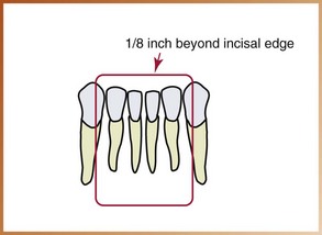
FIGURE 18-14 Approximately one eighth of an inch of the receptor must appear beyond the incisal edges of the teeth.

3. Vertical angulation. The central ray of the x-ray beam must be directed perpendicular (at a right angle) to the imaginary bisector that divides the angle formed by the receptor and the long axis of the tooth.

4. Horizontal angulation. The central ray of the x-ray beam must be directed through the contact areas between teeth.

5. Receptor exposure. The x-ray beam must be centered on the receptor to ensure that all areas of the receptor are exposed. Failure to center the x-ray beam results in a partial image or a cone-cut.

Step-By-Step Procedures

Step-by-step procedures for the exposure of periapical images using the bisecting technique include patient preparation, equipment preparation, and receptor placement methods. Before exposing any receptors using the bisecting technique, infection control procedures (as detailed in Chapter 15) must be completed.

Patient Preparation

After completion of infection control procedures and preparation of the treatment area and supplies, the patient should be seated. After seating the patient, and before the exposure of any periapical images the dental radiographer must prepare the patient for receptor exposure (Procedure 18-1).

PROCEDURE 18-1   Patient Preparation for Bisecting Technique

1. Briefly explain the procedure to the patient before the procedure begins.

2. Position the patient upright in the chair. The level of the chair must be adjusted to a comfortable working height.

3. Adjust the headrest to support the patient’s head. The patient’s head must be positioned such that the arch that is being imaged is parallel to the floor and the midsagittal plane is perpendicular to the floor.

4. Place and secure the lead apron with thyroid collar over the patient.

5. Remove all objects from the patient’s mouth (e.g., dentures, retainers, chewing gum) that may interfere with the procedure. Eyeglasses must also be removed.

Equipment Preparation

After patient preparation, the dental radiographer must complete equipment preparations before exposing any periapicals (Procedure 18-2).

PROCEDURE 18-2   Equipment Preparation for Bisecting Technique

1. Set the exposure factors (kilovoltage, milliamperage, and time) on the x-ray unit according to the recommendations of the receptor manufacturer. Either a short (8-inch) or long (16-inch) position-indicating device (PID) may be used with the bisecting technique; typically, the short PID is preferred.

2. If using a beam alignment device with the bisecting technique, open the sterilized package containing the device, and assemble it over a covered work area.

Exposure Sequence for Receptor Placements

When using the bisecting technique, an exposure sequence, or definite order for periapical receptor placements and exposures, must be followed. The dental radiographer must have an established exposure routine to prevent errors and use time efficiently. Working without an exposure sequence may result in omitting an area or exposing an area twice.

Anterior Exposure Sequence

When exposing periapical receptors with the bisecting technique, always begin with the anterior teeth (canines and incisors). The rationale for beginning in the anterior region is that anterior placements are less likely to cause the patient to gag. Once the gag reflex has been stimulated, the patient may gag on projections that could normally be tolerated. Management of the patient with a hypersensitive gag reflex is discussed in Chapter 24.

With size 2 receptors, a total of six anterior placements are used in the bisecting technique: three maxillary exposures and three mandibular exposures. The recommended anterior periapical exposure sequence for the bisecting technique is as follows (Table 18-2):

TABLE 18-2

Exposure Sequence for Anterior Receptor Placement: Bisecting Technique

image

1. Begin with the maxillary right canine (tooth No. 6).

2. Expose all the maxillary anterior teeth from right to left.

3. End with the maxillary left canine (tooth No. 11).

4. Next, move to the mandibular arch.

5. Begin with the mandibular left canine (tooth No. 22).

6. Expose all the mandibular anterior teeth from left to right.

7. Finish with the mandibular right canine (tooth No. 27).

As previously discussed in Chapter 17, when the dental radiographer works from right to left in the maxillary arch and then from left to right in the mandibular arch, no wasted movement or shifting of the PID occurs (see Figure 17-10). In addition, when working from right to left and then from left to right, the teeth are exposed in ascending numerical order. This exposure sequence allows the dental radiographer easily to keep track of the last exposure if the procedure is interrupted.

Posterior Exposure Sequence

After anterior exposures, the posterior teeth (premolars and molars) are exposed. In each quadrant, always expose the premolar receptor first and then the molar receptor. The rationale for exposing the premolar placement first is as follows:

• Premolar placement is easier for the patient to tolerate.

• Premolar exposure is less likely to evoke the gag reflex.

Eight posterior receptor placements are used in the bisecting technique: 4 maxillary exposures and 4 mandibular exposures. The recommended posterior periapical exposure sequence for the bisecting technique is as follows (Table 18-3):

TABLE 18-3

Exposure Sequence for Posterior Receptor Placement: Bisecting Technique

image

1. Begin with the maxillary right quadrant.

2. Expose the premolar receptor (teeth Nos. 4 and 5) first and then the molar receptor (teeth Nos. 1, 2, and 3).

3. Move to the mandibular right quadrant.

4. Expose the premolar receptor (teeth Nos. 28 and 29) first and then the molar receptor (teeth Nos. 30, 31, and 32).

5. Move to the maxillary left quadrant.

6. Expose the premolar receptor (teeth Nos. 12 and 13) first and then the molar receptor (teeth Nos. 14, 15, and 16).

7. Finish with the mandibular left quadrant.

8. Expose the premolar receptor (teeth Nos. 20 and 21) first, and then finish the posterior periapical placements with exposure of the molar receptor (teeth Nos. 17, 18, and 19).

Receptor Placement for Bisecting Technique

In a complete mouth radiographic series (CMRS) using the bisecting technique, each periapical exposure has a prescribed placement. Receptor placement, or the specific area where the receptor must be positioned before exposure, is dictated by the teeth and surrounding structures that must be included on the resultant dental image. Prescribed placements for the anterior teeth are detailed in Box 18-1 and illustrated in Figure 18-15. Posterior placements are detailed in Box 18-2 and illustrated in Figure 18-16.

BOX 18-1   Prescribed Placements for Anterior Periapical Receptors

Bisecting Technique

Exposure of Maxillary Canine

The entire crown and root of the canine, including the apex and the surrounding structures, must be seen on this image. The interproximal alveolar bone and mesial contact of the canine must also be visible. The lingual cusp of the first premolar usually obscures the distal contact of the canine.

Exposure of Maxillary Incisor

The entire crowns and roots of all four maxillary incisors, including the apices of the teeth and the surrounding structures, must be seen on this image. The interproximal alveolar bone between the central incisors and the central and lateral incisors must also be visible.

Exposure of Mandibular Canine

The entire crown and root of the canine, including the apex and the surrounding structures, must be seen on this image. The interproximal alveolar bone and mesial and distal contacts must also be visible.

Exposure of Mandibular Incisor

The entire crowns and roots of the four mandibular incisors, including the apices of the teeth and the surrounding structures, must be seen on this image. The contacts between the central incisors and between the central and lateral incisors must also be visible. In most cases, it is not necessary to see the distal contacts of the lateral incisors.

BOX 18-2   Prescribed Placements for Posterior Periapical Receptors

Bisecting Technique

Exposure of Maxillary Premolar

All crowns and roots of the first and second premolars and first molar, including the apices, alveolar crests, contact areas, and surrounding bone, must be seen on this image. In addition, the distal contact of the maxillary canine must be visible in this projection.

Exposure of Maxillary Molar

All crowns and roots of the first, second, and third molars, including the apices, alveolar crests, contact areas, surrounding bone, and tuberosity region, must be seen on this image. In addition, the distal contact of the maxillary second premolar must be visible in this projection.

Exposure of Mandibular Premolar

All crowns and roots of the first and second premolars and first molar, including the apices, alveolar crests, contact areas, and surrounding bone, must be seen on this image. In addition, the distal contact of the mandibular canine should be visible in this projection.

Exposure of Mandibular Molar

All crowns and roots of the first, second, and third molars, including the apices, alveolar crests, contact areas, and surrounding bone, must be seen on this image. In addition, the distal contact of the mandibular second premolar must be visible in this projection.

image

FIGURE 18-15 Prescribed placements for anterior periapicals. A, Exposure of the maxillary right canine. B, Exposure of the maxillary incisor. C, Exposure of the maxillary left canine. D, Exposure of the mandibular right canine. E, Exposure of the mandibular incisor. F, Exposure of the mandibular left canine.

image

FIGURE 18-16 Prescribed placements for posterior periapicals. A, Exposure of the maxillary right molar. B, Exposure of the maxillary right premolar. C, Exposure of the maxillary left premolar. D, Exposure of the maxillary left molar. E, Exposure of the mandibular right molar. F, Exposure of the mandibular right premolar. G, Exposure of the mandibular left premolar. H, Exposure of the mandibular left molar.

The specific placements described in this chapter are for a 14-receptor periapical series using size 2 receptors for all anterior and posterior exposures. Variations in the placement or the number of total receptors used may be recommended by other reference sources or individual practitioners (Box 18-3).

BOX 18-3   Guidelines for Receptor Placement with Bisecting Technique

1. When using film, the white side of the film always faces the teeth.

2. Anterior receptors are always placed vertically.

3. Posterior receptors are always placed horizontally.

4. The incisal or occlusal edge of the receptor must extend approximately one eighth of an inch beyond the teeth.

5. When positioning the receptor, always center the receptor over the area to be examined (as defined in the prescribed placements).

Anterior Placement

Anterior placements include the following:

• Two maxillary canine exposures (Procedure 18-3)

PROCEDURE 18-3   Maxillary Canine Exposure

Bisecting Technique (Figure 18-17)

1. Center the receptor on the maxillary canine.

image

image

FIGURE 18-17 Exposure of the maxillary canine. A, Receptor placement.B, Relationship of the receptor, teeth, imaginary bisector, and central ray. C, Exposure of the receptor. D, Resultant image.

2. Position the lower edge of the receptor parallel to the occlusal plane so that one eighth of an inch extends below the incisal edge of the canine.

3. Instruct the patient to “slowly close” on the bite-block or beam alignment device.

4. If not using a beam alignment device, establish the correct vertical angulation by bisecting the angle and directing the central ray perpendicular to the imaginary bisector.

5. If not using a beam alignment device, establish the correct horizontal angulation by directing the central ray between the contacts of the canine and the first premolar.

6. Position the position-indicating device (PID) using the correct vertical and horizontal angulations. Center the PID over the receptor to avoid cone-cutting.

7. Expose the receptor.

• One maxillary incisor exposure (Procedure 18-4)

PROCEDURE 18-4   Maxillary Incisor Exposure

Bisecting Technique (Figure 18-18)

1. Center the receptor on the contact between the two maxillary central incisors.

image

image

FIGURE 18-18 Exposure of the maxillary incisor. A, Receptor placement.B, Relationship among the receptor, teeth, imaginary bisector, and central ray. C, Exposure of the receptor. D, Resultant image.

2. Position the lower edge of the receptor parallel to the occlusal plane so that one eighth of an inch extends below the incisal edges of the teeth.

3. Instruct the patient to “slowly close” on the bite-block or beam alignment device.

4. If not using a beam alignment device, establish the correct vertical angulation by bisecting the angle and directing the central ray perpendicular to the imaginary bisector.

5. If not using a beam alignment device, establish the correct horizontal angulation by directing the central ray between the contacts of the central incisors.

6. Position the position-indicating device (PID) using the correct vertical and horizontal angulations. Center the PID over the receptor to avoid cone-cutting.

7. Expose the receptor.

• Two mandibular canine exposures (Procedure 18-5)

PROCEDURE 18-5   Mandibular Canine Exposure

Bisecting Technique (Figure 18-19)

1. Center the receptor on the mandibular canine.

image

image

FIGURE 18-19 Exposure of the mandibular canine. A, Receptor placement.B, Relationship among the receptor, teeth, imaginary bisector, and central ray. C, Exposure of the receptor. D, Resultant image.

2. Position the upper edge of the receptor parallel to the occlusal plane so that one eighth of an inch extends above the incisal edge of the canine.

3. Instruct the patient to “slowly close” on the bite-block or beam alignment device.

4. If not using a beam alignment device, establish the correct vertical angulation by bisecting the angle and directing the central ray perpendicular to the imaginary bisector.

5. If not using a beam alignment device, establish the correct horizontal angulation by directing the central ray between the contacts of the canine and first premolar.

6. Position the position-indicating device (PID) using the correct vertical and horizontal angulations. Center the PID over the receptor to avoid cone-cutting.

7. Expose the receptor.

• One mandibular incisor exposure (Procedure 18-6)

PROCEDURE 18-6   Mandibular Incisor Exposure

Bisecting Technique (Figure 18-20)

1. Center the receptor on the contact between the two mandibular central incisors.

image

image

FIGURE 18-20 Exposure of the mandibular incisor. A, Receptor placement.B, Relationship among the receptor, teeth, imaginary bisector, and central ray. C, Exposure of the receptor. D, Resultant image.

2. Position the upper edge of the receptor parallel to the occlusal plane so that one eighth of an inch extends above the incisal edges of the teeth.

3. Instruct the patient to “slowly close” on the bite-block or beam alignment device.

4. If not using a beam alignment device, establish the correct vertical angulation by bisecting the angle and directing the central ray perpendicular to the imaginary bisector.

5. If not using a beam alignment device, establish the correct horizontal angulation by directing the central ray between the contacts of the central incisors.

6. Position the position-indicating device (PID) using the correct vertical and horizontal angulations. Center the PID over the receptor to avoid cone-cutting.

7. Expose the receptor.

Size 2 receptor is used for all anterior placements and is positioned vertically.

Posterior Placement

Posterior placements include the following:

• Two maxillary premolar exposures (Procedure 18-7)

PROCEDURE 18-7   Maxillary Premolar Exposure

Bisecting Technique (Figure 18-21)

1. Center the receptor on the maxillary second premolar; the front edge of the receptor should be aligned with the midline of the maxillary canine.

image

image

FIGURE 18-21 Exposure of the maxillary premolar. A, Receptor placement.B, Relationship among the receptor, teeth, imaginary bisector, and central ray. C, Exposure of the receptor. D, Resultant image.

2. Position the lower edge of the receptor parallel to the occlusal plane so that one eighth of an inch extends below the occlusal edges of the teeth.

3. Instruct the patient to “slowly close” on the bite-block or beam alignment device.

4. If not using a beam alignment device, establish the correct vertical angulation by bisecting the angle and directing the central ray perpendicular to the imaginary bisector.

5. If not using a beam alignment device, establish the correct horizontal angulation by directing the central ray between the contacts of the premolars.

6. Position the position-indicating device (PID) using the correct vertical and horizontal angulations. Center the PID over the receptor to avoid cone-cutting.

7. Expose the receptor.

• Two maxillary molar exposures (Procedure 18-8)

PROCEDURE 18-8   Maxillary Molar Exposure

Bisecting Technique (Figure 18-22)

1. Center the receptor on the maxillary second molar; the front edge of the receptor should be aligned with the midline of the maxillary second premolar.

image

image

FIGURE 18-22 Exposure of the maxillary molar. A, Receptor placement.B, Relationship among the receptor, teeth, imaginary bisector, and central ray. C, Exposure of the receptor. D, Resultant image.

2. Position the lower edge of the receptor parallel to the occlusal plane so that one eighth of an inch extends below the occlusal edges of the teeth.

3. Instruct the patient to “slowly close” on the bite-block or beam alignment device.

4. If not using a beam alignment device, establish the correct vertical angulation by bisecting the angle and directing the central ray perpendicular to the imaginary bisector.

5. If not using a beam alignment device, establish the correct horizontal angulation by directing the central ray between the contacts of the molars.

6. Position the position-indicating device (PID) using the correct vertical and horizontal angulations. Center the PID over the receptor to avoid cone-cutting.

7. Expose the receptor.

Charting a Full-Mouth Series

image

• Two mandibular premolar exposures (Procedure 18-9)

PROCEDURE 18-9   Mandibular Premolar Exposure

Bisecting Technique (Figure 18-23)

1. Center the receptor on the mandibular second premolar; the front edge of the receptor should be aligned with the midline of the mandibular canine.

image

image

FIGURE 18-23 Exposure of the mandibular premolar. A, Receptor placement.B, Relationship among the receptor, teeth, imaginary bisector, and central ray. C, Exposure of the receptor. D, Resultant image.

2. Position the upper edge of the receptor parallel to the occlusal plane so that one eighth of an inch extends above the occlusal edges of the teeth.

3. Instruct the patient to “slowly close” on the bite-block or beam alignment device.

4. If not using a beam alignment device, establish the correct vertical angulation by bisecting the angle and directing the central ray perpendicular to the imaginary bisector.

5. If not using a beam alignment device, establish the correct horizontal angulation by directing the central ray between the contacts of the premolars.

6. Position the position-indicating device (PID) using the correct vertical and horizontal angulations. Center the PID over the receptor to avoid cone-cutting.

7. Expose the receptor.

• Two mandibular molar exposures (Procedure 18-10)

PROCEDURE 18-10   Mandibular Molar Exposure

Bisecting Technique (Figure 18-24)

1. Center the receptor on the mandibular second molar; the front edge of the receptor should be aligned with the midline of the mandibular second premolar.

image

image

FIGURE 18-24 Exposure of the mandibular molar. A, Receptor placement.B, Relationship among the receptor, teeth, imaginary bisector, and central ray. C, Exposure of the receptor. D, Resultant image.

2. Position the upper edge of the receptor parallel to the occlusal plane so that one eighth of an inch extends above the occlusal edges of the teeth.

3. Instruct the patient to “slowly close” on the bite-block or beam alignment device.

4. If not using a beam alignment device, establish the correct vertical angulation by bisecting the angle and directing the central ray perpendicular to the imaginary bisector.

5. If not using a beam alignment device, establish the correct horizontal angulation by directing the central ray between the contacts of the molars.

6. Position the position-indicating device (PID) using the correct vertical and horizontal angulations. Center the PID over the receptor to avoid cone-cutting.

7. Expose the receptor.

8. An example of a charting note for a full-mouth series using the bisecting technique is given below:

Size 2 receptor is used for all posterior placements and is positioned horizontally.

Advantages and Disadvantages

As with all intraoral techniques, the bisecting technique has both advantages and disadvantages. The disadvantages of the bisecting technique, however, outweigh the advantages. Therefore, the paralleling technique is preferred over the bisecting technique for the exposure of periapical images and should be used whenever possible.

Advantages of Bisecting Technique

The primary advantage of the bisecting technique is that it can be used without a beam alignment device when the anatomy of the patient (shallow palate, bony growths, sensitive mandibular premolar areas) precludes the use of such a device. Another advantage is decreased exposure time. When a short (8-inch) PID is used with the bisecting technique, a shorter exposure time is recommended.

Disadvantages of Bisecting Technique

The primary disadvantage of the bisecting technique is dimensional distortion. The disadvantages of the bisecting technique can be summarized as follows:

1. Image distortion. Distortion occurs when a short PID is used; a short PID causes increased divergence of x-rays, resulting in image magnification. Distortion also occurs when a tooth (three-dimensional structure) is projected onto a receptor (two-dimensional structure); structures that are farther away from the receptor appear more elongated than those closer to the receptor.

2. Angulation problems. Without the use of a beam alignment device and aiming ring, it is difficult for the dental radiographer to visualize the imaginary bisector and then determine the vertical angulation. Any error in vertical angulation will result in image distortion (elongation or foreshortening).

Helpful Hints

In using the bisecting technique:

image DO set all exposure factors (kilovoltage, milliamperage, time) before placing any receptors in the mouth.

image DO ask patients to remove all intraoral objects and eyeglasses before placing any receptors in the mouth.

image DO use a definite order (exposure sequence) when exposing receptors to avoid errors and to make use of time in an efficient manner.

image DO explain the procedures that will be performed.

image DO instruct patients on exactly how to stabilize the bite-block and remain still during the exposure.

image DO memorize the recommended vertical angulation ranges for each periapical exposure, and use these ranges as a guide when determining PID placement.

image DO direct the central ray perpendicular to the imaginary bisector.

image DO align the opening of the PID parallel to the imaginary bisector.

image DO use the word please; say, “Open, please.”

image DO use praise; tell cooperative patients how much they are helping you.

image DO NOT bend or crimp a film packet; bending of the film causes image distortion.

image DO NOT use words such as hurt. Instead, inform patients that the procedure will be “momentarily uncomfortable.”

image DO NOT make comments such as “Oops.” Patients will lose confidence in your abilities when they hear such comments.

image DO NOT pick up a receptor if you drop it. Leave it on the floor; it has now become contaminated. Instead, remove it and dispose of it when you clean the treatment area.

image DO NOT allow patients to dictate how you should perform your duties. The dental radiographer must always remain in control of the procedures.

image DO NOT begin with posterior exposures; posterior placements may cause patients to gag. Instead, always begin with anterior exposures.

Summary

• The bisecting technique is a technique used to expose periapical images. This technique is based on the concept of bisecting the angle formed by the receptor and the long axis of the tooth.

• In the bisecting technique, (1) the receptor is placed along the lingual surface of the tooth; (2) at the point where the receptor contacts the tooth, the plane of the receptor and the long axis of the tooth form an angle; (3) an imaginary bisector divides the angle in half, or bisects it; and (4) the central ray of the x-ray beam is directed perpendicular to the imaginary bisector.

• In the bisecting technique, beam alignment devices are used to stabilize the receptor. A variety of beam alignment devices and bite-blocks are commercially available.

• A size 2 intraoral receptor is used with the bisecting technique. For anterior exposures, the receptor is always positioned vertically; for posterior exposures, the receptor is always positioned horizontally.

• Horizontal angulation refers to the positioning of the PID in a side-to-side plane. With correct horizontal angulation, the central ray is directed through the contact areas of the teeth, and thus the contact areas on the image appear “opened.” Incorrect horizontal angulation results in overlapped (“unopened”) contacts.

• Vertical angulation refers to the positioning of the PID in an up-and-down plane. With the bisecting technique, the vertical angulation is determined by the imaginary bisector; the central ray is directed perpendicular to the imaginary bisector. Correct vertical angulation results in a dental image that is of the same length as that of the tooth.

• Incorrect vertical angulation results in a dental image that is not of the same length as that of the tooth. Foreshortening of images occurs with excessive vertical angulation, whereas elongation of images results from insufficient vertical angulation.

• Five basic rules exist for the bisecting technique: (1) The receptor must cover the prescribed area of interest; (2) the receptor must be positioned with one eighth of an inch extending beyond the incisal or occlusal surfaces; (3) the central ray must be directed perpendicular to the imaginary bisector that divides the angle formed by the tooth and the receptor; (4) the central ray must be directed through the contact areas between teeth; and (5) the x-ray beam must be centered over the receptor to ensure that all areas of the receptor are exposed.

• Before receptor exposure using the bisecting technique, the dental radiographer must complete infection control procedures, prepare the treatment area and the supplies, seat the patient, explain the procedures to him or her, make chair and headrest adjustments, place the lead apron on the patient, remove intraoral objects and eyeglasses from the patient, set exposure factors, and assemble the beam alignment devices over a covered work area.

• When using the bisecting technique, the dental radiographer always begins with anterior exposures; anterior exposures are less likely to cause gagging. After anterior exposures, the posterior teeth are radiographed. In each quadrant, the premolar region is always exposed first and then the molar region.

• When exposing a complete mouth radiographic series (CMRS) using bisecting technique, each of 14 periapical exposures has a prescribed placement (see Boxes 18-2 and 18-3 and Figures 18-15 and 18-16).

• The advantages of the bisecting technique are that it can be used without a beam alignment device and that it has a shorter exposure time.

• The disadvantages of the bisecting technique are image distortion and angulation problems.

• The paralleling technique is preferred over the bisecting technique and should be used whenever possible.

Bibliography

Frommer, HH, Savage-Stabulas, JJ, Accessory radiographic techniques: Bisecting technique and occlusal technique. Radiology for the dental professional, ed 9, St. Louis, Mosby, 2011.

Johnson, ON, Thomson, EM, Intraoral radiographic procedures. Essentials of dental radiography for dental assistants and hygienists, ed 8, Upper Saddle River, NJ, Pearson Education, Inc, 2007.

Johnson, ON, Thomson, EM, The periapical examination. Essentials of dental radiography for dental assistants and hygienists, ed 8, Upper Saddle River, NJ, Pearson Education, Inc, 2007.

Miles, DA, Van Dis, ML, Razmus, TF. Intraoral radiographic techniques. In: Basic principles of oral and maxillofacial radiology. Philadelphia: Saunders; 1992.

White, SC, Pharoah, MJ, Intraoral radiographic examinations. Oral radiology: principles and interpretation, ed 6, St. Louis, Mosby, 2009.

Quiz Questions

Matching

For questions 1 to 4, refer to Figure 18-25. Match the letter (A to D) of the item shown with the description below.

image

FIGURE 18-25

________ 1. Plane of the receptor

________ 2. Long axis of the tooth

________ 3. Imaginary bisector

________ 4. Central ray

Identification

For questions 5 to 10, refer to Figures 18-26, 18-27, and 18-28. Write in the letter of the item defined in each question.

image

FIGURE 18-26

image

FIGURE 18-27

image

FIGURE 18-28

________ 5. In Figure 18-26, identify the angle that is bisected correctly.

________ 6. In Figure 18-27, identify the central ray that is correctly positioned perpendicular to the imaginary bisector.

________ 7. In Figure 18-28, identify the position-indicating device (PID) that is aligned correctly.

________ 8. In Figure 18-28, identify the vertical angulation that results in foreshortening.

________ 9. In Figure 18-28, identify the vertical angulation that results in elongation.

________ 10. In Figure 18-28, identify the correct vertical angulation.

Fill in the Blank

11. What happens to the dental image when a short (8-inch) PID is used?

_____________________________________________

12. Which size receptor is used with the bisecting technique?

_____________________________________________

13. Which beam alignment device is recommended for use with the bisecting technique because it aids in the alignment of the PID and reduces patient exposure?

_____________________________________________

14. How is the patient’s head positioned before exposing maxillary periapicals with the bisecting technique?

_____________________________________________

15. How is the patient’s head positioned before exposing mandibular periapicals with the bisecting technique?

_____________________________________________

Multiple Choice

________ 16. Which of the following describes the proper direction of the central ray in the bisecting technique?

a. 90 degrees to the long axis of the tooth

b. 90 degrees to the receptor and long axis of the tooth

c. 90 degrees to the receptor

d. 90 degrees to the imaginary bisector

________ 17. Which of the following describes the distance between the receptor and the tooth in the bisecting technique?

a. The receptor is placed as close as possible to the tooth.

b. The receptor is placed away from the tooth and toward the middle of the oral cavity.

c. The receptor is placed parallel to the tooth.

d. None of the above.

________ 18. Which of the following are advantages of the bisecting technique?

a. increased accuracy

b. simplicity of use

c. shorter exposure time

1) 1, 2, and 3

2) 1 and 2

3) 2 and 3

4) 3 only

________ 19. The disadvantages of the bisecting technique outweigh the advantages.

a. true

b. false

Essay

20. State the rule of isometry.

21. Discuss the significance of the shaded areas in Figure 18-29.

image

FIGURE 18-29

22. State the five rules of the bisecting technique.

23. Discuss the patient and equipment preparations that must be completed before using the bisecting technique.

24. Discuss the exposure sequence for the 14 periapical placements using the bisecting technique.

25. Describe each of the 14 periapical placements recommended for use with the bisecting technique.

26. Describe correct and incorrect horizontal angulation.

27. State the recommended vertical angulations for each maxillary periapical exposure using the bisecting technique.

28. State the recommended vertical angulations for each mandibular periapical exposure using the bisecting technique.