After completion of this chapter, the student will be able to do the following:
• Define the key terms associated with the paralleling technique
• State the basic principle of the paralleling technique and illustrate the placement of the receptor, beam alignment device, position-indicating device (PID), and central ray
• Discuss how object–receptor distance affects the radiographic image and how target–receptor distance is used to compensate for such changes
• List the beam alignment devices that can be used with the paralleling technique
• Describe why a beam alignment device is necessary with the paralleling technique
• Identify and label the parts of the Rinn XCP instruments
• Describe the different sizes of receptors used with the paralleling technique and how each receptor is placed in the bite-block
• State the five basic rules of the paralleling technique
• Describe the patient and equipment preparations that are necessary before using the paralleling technique
• Discuss the exposure sequence for 15 periapical receptor placements using the paralleling technique
• Describe each of the 15 periapical receptor placements recommended for use with the XCP instruments
• Summarize the guidelines for periapical receptor positioning
• Explain the modifications in the paralleling technique that are used for a patient with a shallow palate, bony growths, or a sensitive premolar region
• List the advantages and disadvantages of the paralleling technique
In dentistry, the radiographer must master a variety of intraoral radiographic techniques. The paralleling technique is an important technique used to obtain periapical images. Before the dental radiographer can use the paralleling technique, an understanding of the basic concepts and required equipment is necessary. In addition, the dental radiographer must understand patient preparation, equipment preparation, exposure sequencing, and the receptor placement procedures used in the paralleling technique.
The purpose of this chapter is to present basic concepts and to describe patient preparation, equipment preparation, and receptor placement procedures used in the paralleling technique. This chapter also describes modifications of this technique that can be used in patients with certain anatomic conditions, outlines the advantages and disadvantages of the paralleling technique, and reviews helpful hints.
The paralleling technique (also known as the extension cone paralleling [XCP] technique, right-angle technique, and long-cone technique) is one method that can be used to expose periapical and bite-wing image receptors. Before the dental radiographer can competently perform the paralleling technique, a thorough understanding of the terminology, principles, and basic rules governing this technique is necessary. Knowledge of the beam alignment devices and receptors used with the paralleling technique is also required.
An understanding of the following basic terms is necessary before describing the paralleling technique:
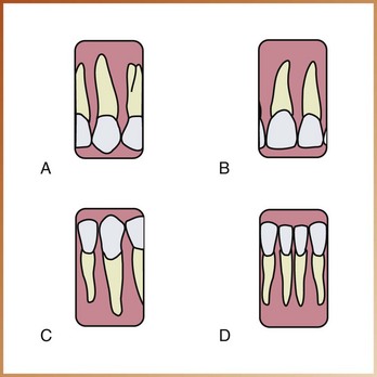
Parallel: Moving or lying in the same plane, always separated by the same distance and not intersecting (Figure 17-1, A)
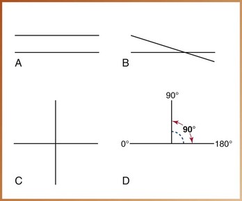
FIGURE 17-1 A, Parallel lines are always separated by the same distance and do not intersect. B, Intersecting lines cross one another. C, Perpendicular lines intersect one another to form right angles. D, A right angle measures 90 degrees and is formed by two perpendicular lines.
Intersecting: To cut across or through (Figure 17-1, B)
Perpendicular: Intersecting at or forming a right angle (Figure 17-1, C)
Right angle: An angle of 90 degrees formed by two lines perpendicular to each other (Figure 17-1, D)
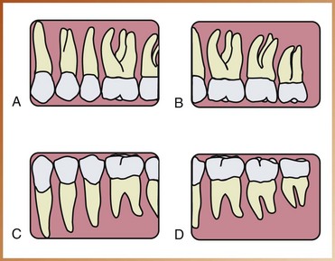
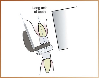
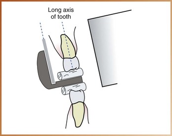
Long axis of the tooth: An imaginary line that divides the tooth longitudinally into two equal halves (Figure 17-2)
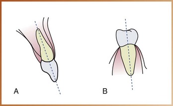
FIGURE 17-2 A, The long axis of the maxillary incisor divides the tooth into two equal halves. B, The long axis of a mandibular premolar divides the tooth into two equal halves.
Central ray: The central portion of the primary beam of x-radiation
As the term paralleling indicates, this technique is based on the concept of parallelism. The basic principles of the paralleling technique can be described as follows (Figure 17-3):
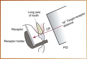
FIGURE 17-3 Positions of the receptor, teeth, and central ray (CR) of the x-ray beam in the paralleling technique. The receptor and the long axis of the tooth are parallel. The central ray is perpendicular to the tooth and the receptor. An increased target–receptor distance (16 inches) is required. PID, position-indicating device.
1. The receptor is placed in the mouth parallel to the long axis of the tooth being radiographed.
2. The central ray of the x-ray beam is directed perpendicular (at a right angle) to the receptor and the long axis of the tooth.
3. A beam alignment device must be used to keep the receptor parallel with the long axis of the tooth. The patient cannot hold the receptor in this manner.
To achieve parallelism between the receptor and the tooth, the receptor must be placed away from the tooth and toward the middle of the oral cavity. Because of the anatomic configuration of the oral cavity (e.g., curvature of palate), the object–receptor distance (distance between receptor and tooth) must be increased to keep the receptor parallel with the long axis of the tooth (Figure 17-4). Because the receptor is placed away from the tooth, image magnification and loss of definition result. As discussed in Chapter 8, increased object–receptor distance results in increased image magnification.
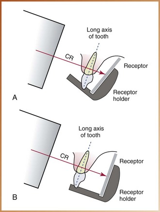
FIGURE 17-4 A, The receptor is placed close to the tooth and is not parallel to the long axis of the tooth. B, Increased object–receptor distance. The receptor is placed away from the tooth and is now parallel with the long axis of the tooth. CR, central ray.
To compensate for image magnification, the target–receptor distance (distance between source of x-rays and receptor) must also be increased to ensure that only the most parallel rays will be directed at the tooth and the receptor. As a result, a long (16-inch) target–receptor distance must be used with the paralleling technique. The paralleling technique is sometimes referred to as the “long-cone technique”; long refers to the length of the cone, or position-indicating device (PID), that is used. The use of a long target–receptor distance in the paralleling technique results in less image magnification and increased definition.
The American Dental Association (ADA) and the American Academy of Oral and Maxillofacial Radiology recommend the use of a rectangular collimator to reduce the amount of radiation the patient receives. Limiting the size of the x-ray beam not only reduces the amount of skin that is exposed but also results in a significant reduction of radiation to the patient, by as much as 70%. The receptor placement procedures are illustrated with a rectangular collimator attached to the end of the PID.
The paralleling technique requires the use of a beam alignment instrument to position the receptor parallel to the long axis of the tooth. Beam alignment devices are used to position an intraoral receptor in the mouth and maintain the receptor in position during exposure (see Chapter 6). Examples of commercially available intraoral beam alignment devices include the following:
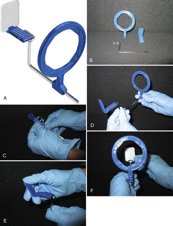
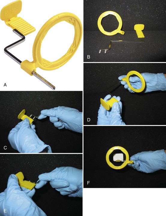
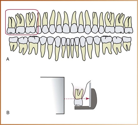
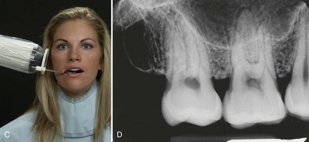
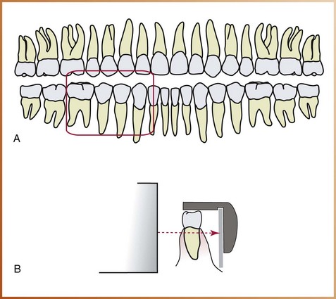
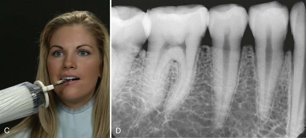
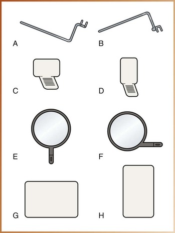
• Rinn XCP instruments (Dentsply Rinn Corporation, Elgin, IL). The XCP (extension cone paralleling) instruments include plastic bite-blocks, plastic aiming rings, and metal indicator arms (Figure 17-5, A). The plastic bite-blocks and aiming rings are color-coded to aid in assembly: blue instruments are used in the anterior regions, yellow instruments are used in the posterior regions, red instruments are used for bite-wing projections, and torquoise instruments are used in endodontic procedures. To reduce the amount of radiation the patient receives, a snap-on ring collimator can be added to the plastic aiming ring.
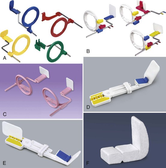
FIGURE 17-5 Beam alignment devices. A, XCP instruments: blue instruments are used in the anterior region, yellow instruments are used in the posterior region, red instruments are used in the bite-wing technique, and torquoise instruments are used for endodontic procedures. B, Rinn XCP-ORA beam alignment devices provide accurate positioning in a system with one ring and one arm for anterior, posterior, and bite-wing projections. C, The Rinn Flip-Ray system uses a rotating bite-block and ring to eliminate multiple beam alignment devices. D, E, The EEZEE Grip (formerly Snap-A-Ray) Xtra intraoral receptor holder is color coded for the anterior and posterior regions. F, An example of a disposable Stabe bite-block. (A, D, E, Courtesy Dentsply Rinn Corporation, Elgin IL.)
• Rinn XCP-ORA instruments have a universal ring and arm positioning system to accommodate anterior, posterior and bitewing projections (Figure 17-5, B).
• The Rinn Flip-Ray system uses a rotating bite-block and ring to eliminate multiple positioning parts.
• EEZEE-Grip receptor holder, formerly known as the Snap-A-Ray. This receptor-holding device can be used in both anterior and posterior areas (Figures 17-5, D and E).
• Stable bite blocks. The Stable bite block is a disposable receptor holder, and is designed for one time use only (Figure 17-5, F).
Some film holders are disposable (e.g., Stabe bite-block) and are designed for one-time use only. Other film holders are reusable (e.g., XCP instruments, Precision film holders, EEZEE-Grip film holder, hemostat with bite-block) and must be sterilized after each use. Additional beam alignment devices for use with imaging receptors will be discussed in Chapter 25, Digital Imaging).
Of all the film holders listed, the Rinn XCP beam alignment instruments with snap-on ring collimators and the Precision film holders are recommended for exposure of periapical receptors. These beam alignment devices are recommended because both include aiming rings that aid in the alignment of the PID with the receptor, and both significantly reduce the amount of patient exposure to radiation. These instruments are simple to position and easy to sterilize. Although only the Rinn XCP beam alignment instruments are illustrated in this text, the same principles apply to all the film holders listed.
The size of the intraoral receptor used with the paralleling technique depends on the teeth being radiographed, as follows:
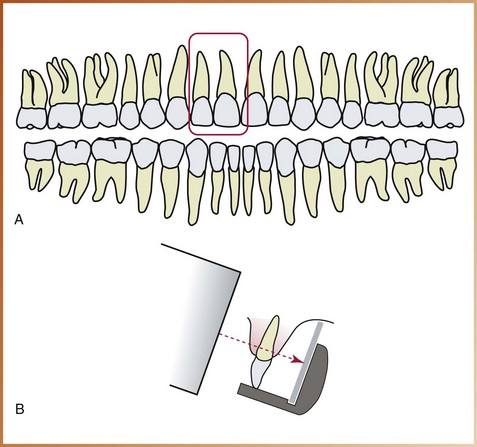
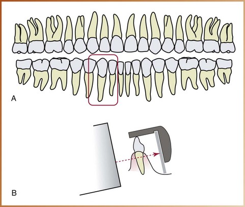
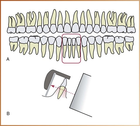
• In the anterior regions, size 1 receptor is used; this narrow size is needed to permit placement high in the palate without bending or curving. Size 1 is always positioned with the long portion of the receptor in a vertical (upright) direction.
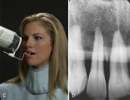
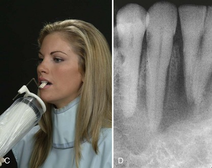
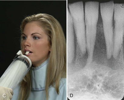
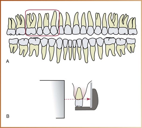
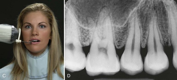
• In the posterior regions, size 2 receptor is used. Size 2 is always placed with the long portion of the receptor in a horizontal (sideways) direction.
Five basic rules should be followed when using the paralleling technique.
1. Receptor placement. The receptor must be positioned to cover the prescribed area of teeth to be examined. Specific placements are detailed in the Procedures sections of this chapter.
2. Receptor position. The receptor must be positioned parallel to the long axis of the tooth. The receptor and beam alignment device must be placed away from the teeth and toward the middle of the oral cavity (see Figure 17-3).
3. Vertical angulation. The central ray of the x-ray beam must be directed perpendicular (at a right angle) to the receptor and the long axis of the tooth (see Figure 17-3).
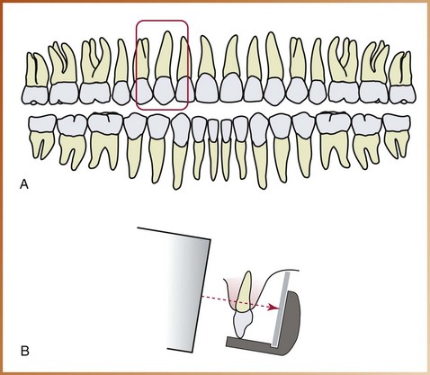
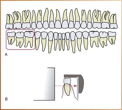
4. Horizontal angulation. The central ray of the x-ray beam must be directed through the contact areas between teeth (Figure 17-6).
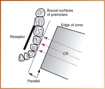
FIGURE 17-6 In this diagram, x-rays pass through the contact areas of the premolars because the central ray (CR) is directed through the contacts and perpendicular to the receptor. If the central ray is not directed through the contacts, overlap of the premolar contacts occurs.
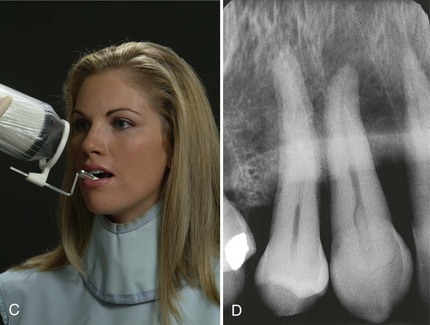
5. Film receptor exposure. The x-ray beam must be centered on the receptor to ensure that all areas are exposed. Failure to center the x-ray beam results in a partial image on the receptor or a “cone-cut.” Cone-cuts can be produced with either a round PID or a rectangular PID. (Figure 17-7). Cone-cuts are discussed in Chapter 20.
Step-by-step procedures for the exposure of periapical receptors using the paralleling technique include patient preparation, equipment preparation, and receptor placement methods. Exposure of bite-wing receptors using the paralleling technique is discussed in Chapter 19. Before exposing any receptors using the paralleling technique, infection control procedures (as detailed in Chapter 15) must be completed.
After completion of infection control procedures and preparation of the treatment area and supplies, the patient should be seated. After seating the patient, the dental radiographer must prepare the patient before the exposure of any receptors (Procedure 17-1).
After patient preparation, equipment must also be prepared before the exposure of any receptors (Procedure 17-2).
When using the paralleling technique, an exposure sequence, or definite order for periapical receptor placement and exposure, must be followed. The dental radiographer must have an established exposure routine to prevent errors and to use time efficiently. Working without an exposure sequence may result in omitting an area or in exposing an area to x-radiation twice.
When exposing periapical receptors with the paralleling technique, always begin with the anterior teeth (canines and incisors), for the following reasons:
• The receptor (size 1) used for anterior exposures is small, less uncomfortable, and easier for the patient to tolerate.
• The more tolerable anterior placements allow the patient to become accustomed to the beam alignment device used in the paralleling technique.
• Anterior placements are less likely to cause the patient to gag. Once the gag reflex is stimulated, the patient may gag on receptor placements that might normally be tolerated. Management of the patient with a hypersensitive gag reflex is discussed in Chapter 24.
With the size 1 receptor, a total of 7 anterior placements may be used in the paralleling technique: 4 maxillary exposures and 3 mandibular exposures. If size 2 receptor is used instead, 6 anterior placements are used: 3 maxillary exposures and 3 mandibular exposures. The authors recommend the use of size 1 receptors; the recommended anterior periapical exposure sequence for the Rinn XCP beam alignment instruments illustrated in this text is as follows (Table 17-1):
TABLE 17-1
Exposure Sequence for Anterior Receptor Placements (with Rinn XCP Instruments): Paralleling Technique
1. Assemble the anterior XCP instrument.
2. Begin with the maxillary right canine (tooth No. 6).
3. Radiograph all the maxillary anterior teeth from right to left.
4. End with the maxillary left canine (tooth No. 11).
5. Next, move to the mandibular arch.
6. Begin with the mandibular left canine (tooth No. 22).
7. Radiograph all the mandibular anterior teeth from left to right.
8. Finish the anterior periapical exposures with the mandibular right canine (tooth No. 27).
When the dental radiographer works from right to left in the maxillary arch and then from left to right in the mandibular arch, no wasted movement or shifting of the PID occurs (Figure 17-10).
FIGURE 17-10 When exposing maxillary anterior receptors, work from the right to the left. Then, expose the mandibular anterior receptors from the left to the right. No unnecessary movements of the PID result.
In addition, when working from right to left and then from left to right, teeth are radiographed in ascending numerical order, as follows:
This exposure sequence allows the dental radiographer to keep track of the last exposure easily even when interruptions occur during the procedure.
After the anterior exposures are completed, the posterior teeth (premolars and molars) are radiographed. In each quadrant, always expose the premolar receptor first and then the molar receptor, for the following reasons:
• Premolar placement is easier for the patient to tolerate.
• Premolar placement is less likely to evoke the gag reflex.
Eight posterior placements may be used in the paralleling technique: 4 maxillary exposures and 4 mandibular exposures. The recommended exposure sequence for the posterior receptor placements varies, depending on the beam alignment device used. The recommended posterior periapical exposure sequence for the Rinn XCP beam alignment instruments illustrated in this text is as follows (Table 17-2):
TABLE 17-2
Exposure Sequence for Posterior Receptor Placements (with Rinn XCP Instruments): Paralleling Technique
1. Begin with the maxillary right quadrant.
2. Assemble the posterior XCP instrument for this area.
3. Expose the premolar receptor (teeth Nos. 4 and 5) first, and then expose the molar receptor (teeth Nos. 1, 2, and 3).
4. Without reassembling the XCP instrument, move to the mandibular left quadrant.
5. Expose the premolar receptor (teeth Nos. 20 and 21) first, and then expose the molar receptor (teeth Nos. 17, 18, and 19).
6. Move to the maxillary left quadrant and reassemble the posterior XCP instrument over a covered work surface for this area.
7. Expose the premolar receptor (teeth Nos. 12 and 13) first, and then the molar receptor (teeth Nos. 14, 15, and 16).
8. Finish with the mandibular right quadrant.
9. Expose the premolar receptor (teeth Nos. 28 and 29) first, and then end the posterior periapical exposures with the exposure of the molar receptor (teeth Nos. 30, 31, and 32).
In a complete mouth radiographic series (CMRS) using the paralleling technique, each periapical exposure has a prescribed placement. Receptor placement, or the specific area where the receptor must be positioned before exposure, is dictated by the specific teeth and their surrounding structures that must be included on the resultant image. Prescribed receptor placements for the anterior teeth are described in Box 17-1 and illustrated in Figure 17-11. Posterior placements are described in Box 17-2 and illustrated in Figure 17-12.
FIGURE 17-11 Prescribed placements for anterior periapical receptors. A, Exposure of the maxillary canine. B, Exposure of the maxillary lateral and central incisors. C, Exposure of the mandibular canine. D, Exposure of the mandibular lateral and central incisors.
FIGURE 17-12 Prescribed placements for posterior periapical receptors. A, Exposure of the maxillary premolar. B, Exposure of the maxillary molar. C, Exposure of the mandibular premolar. D, Exposure of the mandibular molar.
The specific placements described in this chapter are for a 15-receptor periapical series using size 1 receptors for anterior exposures and size 2 receptors for posterior exposures. Variations in placement or the number of total receptors may be recommended by other reference sources or individual practitioners. Box 17-3 lists guidelines for periapical positioning used with the paralleling technique.
The anterior XCP instrument is used for all anterior receptor placements. After the anterior XCP instrument has been assembled, a size 1 receptor is inserted vertically into the bite-block and secured in the slot. Anterior placements typically include the following:
• Two maxillary canine exposures (Procedure 17-3)
• Two maxillary incisor exposures (Procedure 17-4)
• Two mandibular canine exposures (Procedure 17-5)
• One mandibular incisor exposure (Procedure 17-6)
The posterior XCP instrument is used for all posterior receptor placements. After the posterior XCP instrument has been assembled, a size 2 receptor is inserted horizontally into the bite-block and secured in the slot. Posterior placements typically include the following:
• Two maxillary premolar exposures (Procedure 17-7)
• Two maxillary molar exposures (Procedure 17-8)
• Two mandibular premolar exposures (Procedure 17-9)
• Two mandibular molar exposures (Procedure 17-10)
Modifications in the paralleling technique may be used to accommodate variations in anatomic conditions. Such modifications may be necessary when a patient has a shallow palate, bony growths, or a sensitive mandibular premolar region.
Parallelism between the receptor and the long axis of the tooth is difficult to accomplish in a patient with a shallow palate (roof of the mouth), also known as a low palatal vault. In a patient with a shallow palate, tilting of the bite-block occurs, which results in a lack of parallelism between the receptor and the long axis of the tooth. If the lack of parallelism between the receptor and the long axis of the tooth does not exceed 20 degrees, the resultant image is generally acceptable (Figure 17-21). When the lack of parallelism is greater than 20 degrees, a modification in technique is necessary, as follows:
FIGURE 17-21 Tilting of the bite-block results in a lack of parallelism between the receptor and the long axis of the tooth. When the lack of parallelism is less than 20 degrees (as shown in this diagram), the image is generally acceptable.
• Cotton rolls. To position the receptor parallel to the long axis of the tooth, two cotton rolls can be placed, one on each side of the bite-block (Figure 17-22). As a result, however, periapical coverage is reduced.
FIGURE 17-22 Two cotton rolls can be used to position the receptor parallel to the long axis of the tooth.
• Vertical angulation. To compensate for the lack of parallelism, the vertical angulation can be increased by 5 to 15 degrees more than the XCP instrument indicates. However, image distortion occurs as a result.
A torus (plural, tori) is a bony growth seen in the oral cavity. A maxillary torus (torus palatinus) is a nodular mass of bone seen along the midline of the hard palate (Figure 17-23). Mandibular tori (singular, torus mandibularis) are bony growths along the lingual aspect (tongue side) of the mandible (Figure 17-24). When using the paralleling technique, maxillary and mandibular tori can cause problems with receptor placement, and modifications in technique are necessary, as follows:
• For maxillary torus, the receptor must be placed on the far side of the torus (not on the torus) and then exposed (Figure 17-25, A). Periapical radiographs illustrate the radiopaque borders of a maxillary torus (Figure 17-25, B).
FIGURE 17-25 A, If a maxillary torus is present, the receptor must be placed on the far side of the torus and then exposed. B, Periapical radiographs reveal a maxillary torus as seen by the radiopaque areas superior to the apices of the teeth. (B, from White SC, Pharoah MJ: Oral radiology: principles and interpretation, ed 5, St. Louis, 2004, Mosby.)
• For mandibular tori, the receptor must be placed between the tori and the tongue (not on the tori) and then exposed (Figure 17-26, A). Mandibular tori are also seen radiographically as dense radiopacities (Figure 17-26, B).
FIGURE 17-26 A, If mandibular tori are present, the receptor must be placed on the far side of the tori and then exposed. B, Bilateral mandibular tori are seen as dense radiopacities in the region of the canine and the first premolar. (B, from White SC, Pharoah MJ: Oral radiology: principles and interpretation, ed 5, St. Louis, 2004, Mosby.)
The anterior floor of the mouth area can be a very sensitive region. When periapical placements cause discomfort in the mandibular premolar region, a modification in technique is necessary, as follows:
• Receptor placement. The receptor must be placed under the tongue to avoid impinging on muscle attachments and the sensitive lingual gingiva. When inserting the beam alignment device into the mouth, the receptor is tipped away from the tongue and toward the teeth being examined while the bite-block is placed firmly on the mandibular premolars. When the patient closes on the bite-block, the receptor is moved into the proper position (Figure 17-27).
FIGURE 17-27 Positioning of the XCP instrument in the sensitive mandibular premolar area. A, The receptor is tipped away from the tongue while the bite-block is placed firmly on the mandibular premolars. B, When the patient closes on the bite-block, the receptor is moved into proper position.
• Film. The lower edge of the film can be gently curved, or softened, to prevent discomfort. Bending or creasing the film, however, must be avoided.
As with all intraoral techniques, the paralleling technique has both advantages and disadvantages. The advantages of the paralleling technique, however, outweigh the disadvantages.
The primary advantage of the paralleling technique is that it produces a radiographic image without dimensional distortion. In addition, it is uncomplicated and can be easily repeated when serial radiographs are indicated. The advantages of the paralleling technique can be summarized as follows:
• Accuracy. The paralleling technique produces an image that has dimensional accuracy; the image is highly representative of the actual tooth. The radiographic image is free of distortion and exhibits maximum detail and definition.
• Simplicity. The paralleling technique is simple and is easy to learn and use. The use of a beam alignment device eliminates the need for the dental radiographer to determine horizontal and vertical angulations and also eliminates the chances of dimensional distortion.
• Duplication. The paralleling technique is easy to standardize and can be accurately duplicated, or repeated, when serial radiographs are indicated. As a result, comparisons of serial radiographs exposed using the paralleling technique have great validity.
The primary disadvantage of the paralleling technique is receptor placement. Patient discomfort may also be a problem. The disadvantages of the paralleling technique can be summarized as follows:
• Receptor placement. Because a beam alignment device must be used with the paralleling technique, receptor placement may be difficult for the dental radiographer. Difficulties may be encountered with the pediatric patient or with adult patients who have a small mouth or a shallow palate. Such placements become less problematic as the dental radiographer becomes more proficient at using the paralleling technique.
• Discomfort. The beam alignment device used to position the receptor in the paralleling technique may impinge on the oral tissues and cause discomfort for the patient.
In using the paralleling technique:
DO set all exposure factors (kilovoltage, milliamperage, time) before placing any receptors in the mouth.
DO ask patients to remove all intraoral objects and eyeglasses before placing any receptors in the mouth.
DO use a definite order (exposure sequence) when exposing receptors to avoid errors and to make efficient use of time.
DO place each film in the bite-block with the “dot in the slot.” The identification dot must be located at the occlusal or incisal end of the film; this facilitates film mounting and ensures that the dot will not interfere with the diagnosis in the periapical area.
DO explain the radiographic procedures that will be performed; instruct patients on how to close and remain still during the exposure.
DO communicate clearly with patients; patients are more likely to be tolerant of discomfort when they understand why a receptor must be placed in a specific area.
DO use the word please; say, “Open, please.”
DO use praise; tell cooperative patients how much they are helping you.
DO instruct patients to “slowly close”; when patients close slowly, the musculature relaxes and thus discomfort is reduced.
DO align the PID such that the opening of the PID and the rectangular collimator are flush with the aiming ring of the XCP instrument.
DO NOT bend or crimp a film packet; excessive film bending causes distortion of the image.
DO NOT use words such as hurt. Instead, inform patients that the procedure will be “momentarily uncomfortable.”
DO NOT make comments such as “Oops” or other statements that indicate a lack of control in a situation. Patients will lose confidence in your abilities when they hear such comments.
DO NOT pick up a receptor if you drop it. Leave it on the floor, as it has now become contaminated. Instead, remove it and dispose of it when you clean the treatment area.
DO NOT allow patients to dictate how you should perform your duties. Some patients need to be handled firmly. The dental radiographer must always remain in control of the procedures.
DO NOT begin with posterior exposures; posterior placements may cause patients to gag. Instead, always begin with anterior exposures.
DO NOT position receptors on top of a torus (or tori); the apical regions of the teeth will not be seen on the resultant radiograph. Instead, always position receptors behind the torus (or tori).
• In the paralleling technique used to obtain periapical and bite-wing images, the receptor is placed in the mouth parallel to the long axis of the tooth, and the central ray is directed perpendicular to the receptor and the long axis of the tooth. To achieve parallelism between the receptor and the tooth, the receptor must be placed away from the tooth and toward the middle of the oral cavity.
• In the paralleling technique, a beam alignment device must be used to position the receptor parallel to the long axis of the tooth. A variety of beam alignment devices are commercially available.
• The sizes of intraoral receptors used in the paralleling technique depend on the teeth being radiographed. With anterior teeth, size 1 receptors are typically used; with posterior teeth, size 2 receptors are typically used.
• The five basic rules with regard to the paralleling technique are as follows: (1) The receptor must cover the prescribed area of interest; (2) the receptor must be positioned parallel to the long axis of the tooth; (3) the central ray must be directed perpendicular to the receptor and the long axis of the tooth; (4) the central ray must be directed through the contact areas between teeth; and (5) the x-ray beam must be centered over the receptor to ensure that all areas of the receptor are exposed.
• Before the radiographic procedure using the paralleling technique begins, ensure that you take all infection control measures, prepare the treatment area and the supplies, seat the patient and explain the radiographic procedures to him or her, make the necessary chair and headrest adjustments, place the lead apron on the patient, remove any intraoral objects and eyeglasses, set the exposure factors, and assemble the beam alignment devices.
• When using the paralleling technique, always begin with anterior exposures (easier for patient to tolerate, more comfortable, less likely to cause gagging), and then move on to the posterior regions. In each quadrant, always expose the premolar receptor first and then the molar receptor.
• In a complete mouth radiographic series (CMRS) using paralleling technique, each periapical exposure has a prescribed receptor placement (see Boxes 17-1 and 17-2 and Figures 17-11 and 17-12).
• Modifications in paralleling technique may be necessary when a patient has a low or shallow palate, bony growths, or a sensitive mandibular premolar region.
• The advantages of the paralleling technique include the following: (1) it produces images with dimensional accuracy, (2) it is simple and easy to learn and use, (3) it is easy to standardize, and (4) it can be accurately repeated.
• The disadvantages of the paralleling technique are as follows: (1) placements of receptors may be difficult for the dental radiographer and (2) the beam alignment device may cause patient discomfort.
ADA Council on Scientific Affairs. An update on radiographic practices: information and recommendations. J Am Dent Assoc. 2001;132:234.
Frommer, HH, Savage-Stabulas, JJ, Intraoral technique: the paralleling method. Radiology for the dental professional, ed 9, St. Louis, Mosby, 2011.
Johnson, ON, McNally, MA, Essay, CE, Intraoral radiographic procedures. Essentials of dental radiography for dental assistants and hygienists, ed 6, Norwalk, CT, Appleton & Lange, 1999.
Johnson, ON, McNally, MA, Essay, CE, The periapical examination. Essentials of dental radiography for dental assistants and hygienists, ed 6, Norwalk, CT, Appleton & Lange, 1999.
Miles, DA, Van Dis, ML, Jensen, CW, Williamson, GF, Intraoral radiographic technique. Radiographic imaging for dental auxiliaries, ed 4, Philadelphia, Saunders, 2009.
Miles, DA, Van Dis, ML, Razmus, TF. Intraoral radiographic techniques. In: Basic principles of oral and maxillofacial radiology. Philadelphia: Saunders; 1992.
White, SC, Pharoah, MJ, Intraoral radiographic examinations. Oral radiology: principles and interpretation, ed 6, St. Louis, Mosby, 2009.
For questions 1 to 8, refer to Figure 17-28. Match the letters (A to H) of the appropriate items with the descriptions below:
FIGURE 17-28
9. What happens to the image when the object–receptor distance is increased?
10. What piece of equipment is required to hold the receptor parallel to the long axis of the tooth in the paralleling technique?
11. What do the letters X, C, and P refer to?
12. What size receptor is typically used with the anterior XCP instrument?
13. What size receptor is used with the posterior XCP instrument?
14. Which beam alignment devices are recommended for use with the paralleling technique to reduce radiation exposure of the patient?
15. How is the patient’s head positioned before exposing receptors?
________ 16. Why is an increased target–receptor distance required in the paralleling technique?
________ 17. Which of the following describes the relationship of the central ray to the receptor in the paralleling technique?
a. 20 degrees to the long axis of the tooth
b. 90 degrees to the receptor and long axis of the tooth
c. 75 degrees to the long axis of the tooth
d. 15 degrees to the receptor and the long axis of the tooth
________ 18. Which of the following definitions is incorrect?
a. parallel: always separated by the same distance
b. intersecting: to cut through
________ 19. Which of the following describes the relationship between the receptor and the long axis of the tooth in the paralleling technique?
a. The receptor and the tooth are parallel to each other.
b. The receptor and the tooth are at right angles to each other.
c. The receptor and the tooth are perpendicular to each other.
________ 20. Which of the following describes the distance between the receptor and the tooth in the paralleling technique?
a. The receptor is placed as close as possible to the tooth.
b. The receptor is placed away from the tooth and toward the middle of the oral cavity.
________ 21. Which of the following about receptor placement is correct?
a. Anterior receptors are placed horizontally.
b. Anterior receptors are placed vertically.
________ 22. Which of the following about the exposure sequence for periapical receptors is incorrect?
a. Anterior receptors are always exposed before posterior receptors.
b. Either anterior or posterior receptors may be exposed first.
c. In posterior quadrants, the premolar receptor is always exposed before the molar receptor.
d. When exposing anterior receptors, work from the patient’s right to left in the maxillary arch, and then work from left to right in the mandibular arch.
________ 23. Which of the following about the lack of parallelism between the receptor and the long axis of the tooth is correct?
a. If the lack of parallelism is greater than 30 degrees, the image is generally acceptable.
b. If the lack of parallelism is less than 20 degrees, the image is generally acceptable.
c. If the lack of parallelism is less than 50 degrees, the image is generally acceptable.
d. If the lack of parallelism is greater than 50 degrees, the image is generally acceptable.
________ 24. Which of the following are advantages of the paralleling technique?
________ 25. The advantages of the paralleling technique outweigh the disadvantages.
26. State the basic principle of the paralleling technique.
27. Describe why a beam alignment device must be used in the paralleling technique.
28. State the five rules of the paralleling technique.
29. Discuss the patient and equipment preparations that must be completed before using the paralleling technique.
30. Discuss the exposure sequence for 15 periapical receptor placements using the paralleling technique.
31. Describe each of the 15 periapical receptor placements that are recommended for use with the XCP instruments.
32. Summarize the guidelines for periapical receptor positioning with the paralleling technique.
33. Explain the modifications in the paralleling technique that are used for a shallow palate, bony growths, or a sensitive premolar region.