Basic Concepts
The bite-wing technique (also known as the interproximal technique) is a method used to examine the interproximal surfaces of teeth. Before the dental radiographer can competently use this technique, a thorough understanding of the terminology, principles, and basic rules of the bite-wing technique is necessary. In addition, a knowledge of the beam alignment devices, sizes of receptors, and angulations of the position-indicating device (PID) used with the bite-wing technique is also required.
Terminology
An understanding of the following basic terms is necessary before describing the bite-wing technique:
Interproximal: Between two adjacent surfaces.
Interproximal examination: Intraoral examination used to inspect the crowns of both maxillary and mandibular teeth on a single image.
Bite-wing receptor: Type of receptor used in interproximal examination. The bite-wing receptor has a “wing,” or tab, and the patient “bites” on the wing to stabilize the receptor.
Alveolar bone: Bone that supports and encases the roots of teeth (Figure 19-1).
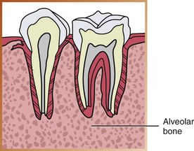
FIGURE 19-1 Alveolar bone. (Adapted from Haring JI, Lind LJ: Radiographic interpretation for the dental hygienist, Philadelphia, 1993, Saunders.)
Crestal bone: Coronal portion of alveolar bone found between teeth; also known as the alveolar crest (Figure 19-2).

FIGURE 19-2 Crestal bone is the most coronal portion of alveolar bone found between teeth. (Adapted from Haring JI, Lind LJ: Radiographic interpretation for the dental hygienist, Philadelphia, 1993, Saunders.)
Contact areas: The area of a tooth that touches an adjacent tooth; the area where adjacent tooth surfaces contact each other (Figure 19-3).
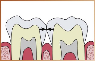
FIGURE 19-3 Contact areas are areas where adjacent tooth surfaces contact each other. (From Haring JI, Lind LJ: Radiographic interpretation for the dental hygienist, Philadelphia, 1993, Saunders.)
Horizontal bite-wing: The bite-wing receptor is placed in the mouth with the long portion of the receptor in a horizontal direction.
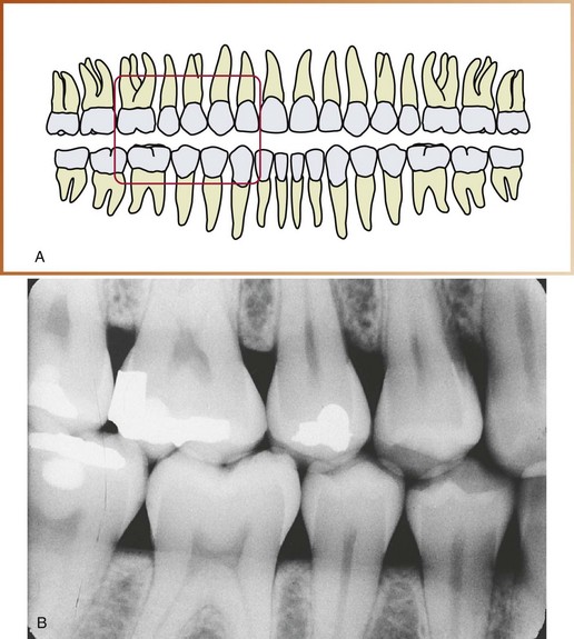
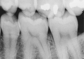
Opened contacts: On a dental image, opened contacts appear as thin radiolucent lines between adjacent tooth surfaces (Figure 19-4).
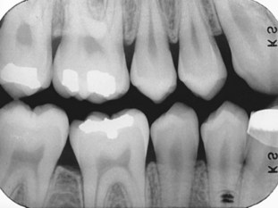
FIGURE 19-4 The opened contacts in the premolar region appear as thin radiolucent lines. Note that the occlusal plane is positioned horizontally along the midline of the long axis of the image. (From Haring JI, Lind LJ: Radiographic interpretation for the dental hygienist, Philadelphia, 1993, Saunders.)
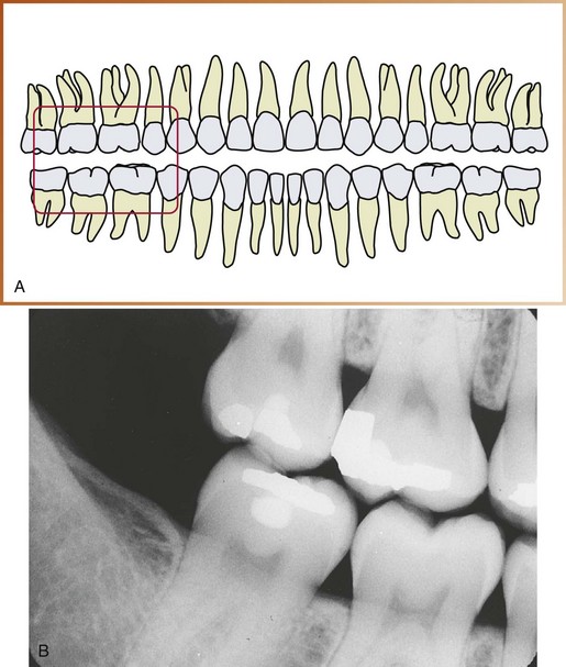
Overlapped contacts: On a dental image, the area where the contact area of one tooth is superimposed over the contact area of an adjacent tooth is referred to as overlapped contacts (Figure 19-5).
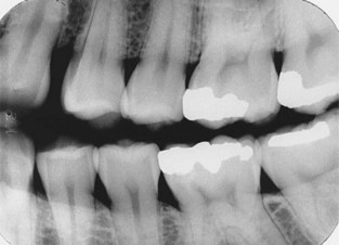
FIGURE 19-5 A nondiagnostic bite-wing image with overlapped interproximal contacts. (From Haring JI, Lind LJ: Radiographic interpretation for the dental hygienist, Philadelphia, 1993, Saunders.)
Vertical bite-wing: The bite-wing receptor is placed in the mouth with the long portion of the receptor in a vertical direction.
Principles of Bite-Wing Technique
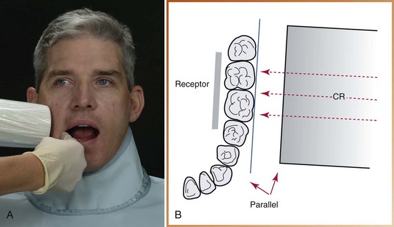
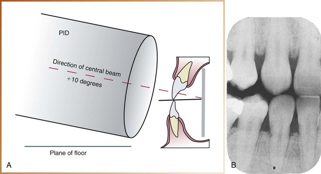
The basic principles of the bite-wing technique can be described as follows (Figure 19-6):
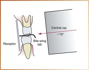
FIGURE 19-6 Positions of the receptor, bite-wing tab, and central ray in the bite-wing technique. The receptor is parallel to the crowns in the maxillary and mandibular teeth. The central ray is directed downward (+10 degrees of vertical angulation).
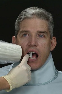
1. The receptor is placed in the mouth parallel to the crowns of both maxillary and mandibular teeth.
2. The receptor is stabilized when the patient bites on the bite-wing tab or the bite-wing beam alignment device.
3. The central ray of the x-ray beam is directed through the contacts of teeth, using a vertical angulation of +10 degrees.
Beam Alignment Device and Bite-Wing Tab
In the bite-wing technique, either a beam alignment device or a bite-wing tab is used to stabilize the receptor.
Bite-Wing Beam Alignment Device
A beam alignment device is a device used to position an intraoral receptor in the mouth and maintain the receptor in position during the radiographic procedure (see Chapter 6). Beam alignment devices eliminate the need for the patient to stabilize the receptor with a bite-wing tab. An example of a commercially available intraoral bite-wing beam alignment device is the XCP bite-wing instrument; this instrument may be used to stabilize the bite-wing receptor in a horizontal or vertical direction.
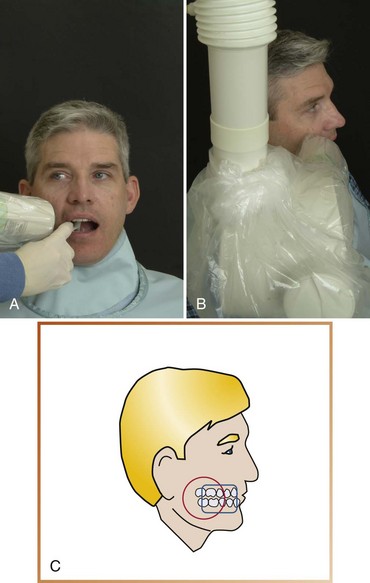
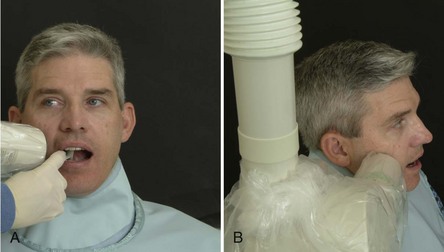
• Rinn XCP bite-wing instruments (Rinn Corporation, Elgin, IL). The XCP bite-wing instruments include plastic horizontal and vertical bite-blocks, plastic aiming rings, and metal indicator arms (Figure 19-7, A, B). To reduce the amount of radiation the patient receives, a snap-on ring collimator can be added to the plastic aiming ring. These beam alignment devices are reusable and must be sterilized after each use.
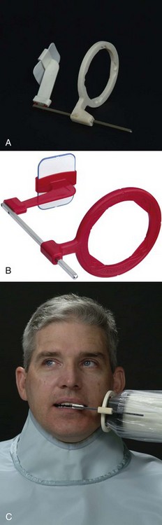
FIGURE 19-7 A, Beam alignment device for horizontal bite-wings. Note external localizing ring used for the position-aiming tube of the x-ray machine to ensure that the entire receptor is covered by the x-ray beam. B, Beam alignment device for vertical bite-wings. C, Rectangular collimation used with a bite-wing exposure.
The Rinn XCP bite-wing instruments with collimators are recommended for bite-wing exposures. These devices include aiming rings that assist in the alignment of the PID and collimators, significantly reducing the amount of radiation exposure. These instruments are simple to position and easy to sterilize. As mentioned in Chapter 17, the American Dental Association (ADA) and the American Academy of Oral and Maxillofacial Radiology recommend the use of a rectangular collimator to reduce the amount of radiation the patient receives (Figure 19-7, C). For information about the use of the Rinn XCP bite-wing instruments, the dental radiographer should refer to the instructions provided by the manufacturer.
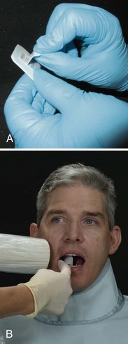
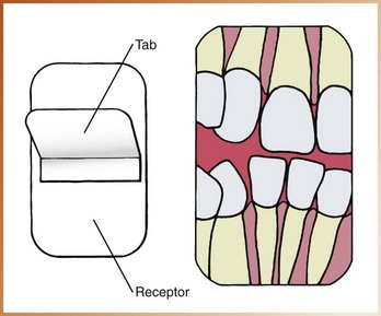
Bite-Wing Tab
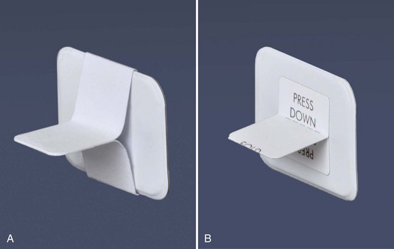
As an alternative to a beam alignment device, a receptor can be fitted with a bite-wing tab (also called a bite loop or bite tab). The bite-wing tab is a heavy paperboard tab or loop that is fitted around an intraoral receptor and is used to stabilize the receptor during the procedure (Figure 19-8, A). When using film, the bite-wing is oriented in the bite loop so that the tab portion extends from the white side (tube side) of the film. Bite-wing receptors may be purchased with the tabs attached, or they may be constructed by assembling a periapical receptor and a bite-wing tab. Bite-wing tabs may be used on horizontal or vertical bite-wing projections. Bite loops are available in various sizes; adhesive bite tabs are also available (Figure 19-8, B).
Bite-Wing Receptors
As described in Chapter 7, three sizes of bite-wing receptors (0, 2, and 3) are available. Figure 7-14 (pp. 69–70) summarizes the measurements and uses of these receptors.
• Size 0 is used to examine the posterior teeth of children with primary dentitions. This receptor is always placed with the long portion of the receptor in a horizontal (sideways) direction.
• Size 2 is used to examine the posterior teeth in adults and may be placed horizontally or vertically. For most bite-wing exposures, a size 2 receptor is placed with the long portion of the receptor in a horizontal direction. When a vertical posterior bite-wing exposure is indicated, a size 2 receptor is placed with the long portion of the receptor in a vertical direction.
• Size 3 is longer and narrower than the standard size 2 receptor and is used only for bite-wing exposures. One receptor is exposed on each side of the arch to examine all the premolar and molar contact areas. A size 3 receptor is placed with the long portion of the receptor in a horizontal direction.
In the adult patient, a size 2 receptor is recommended for bite-wing exposures. The size 3 receptor is not recommended. With a size 3 receptor, overlapped contacts often result because of the difference in the curvature of the arch between the premolar and molar areas. In addition, the crestal bone areas may not be adequately seen on the dental images of patients with bone loss because of the narrow shape of the receptor.
Position-Indicating Device Angulation
In the bite-wing technique, the angulation of the PID is critical. As defined in Chapter 18, angulation is a term used to describe the alignment of the central ray of the x-ray beam in both horizontal and vertical planes. Angulation can be varied by moving the PID in a horizontal or vertical direction. Use of the XCP bite-wing instruments with aiming rings dictates the proper PID angulation. However, when a bite-wing tab is used, the dental radiographer must determine both horizontal and vertical angulations.
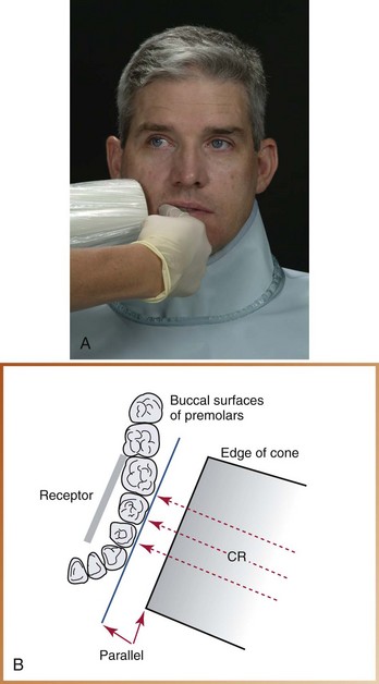
Horizontal Angulation
As described in Chapter 18, horizontal angulation refers to the positioning of the central ray in a horizontal, or side-to-side, plane (see Figure 18-7). The bite-wing, paralleling, and bisecting techniques all use the same principles of horizontal angulation.
Correct Horizontal Angulation: With correct horizontal angulation, the central ray is directed perpendicular to the curvature of the arch and through the contact areas of teeth (see Figure 18-8). As a result, the contact areas on the exposed image appear “opened” and can be examined for evidence of caries (see Figure 19-4).
Incorrect Horizontal Angulation: Incorrect horizontal angulation results in overlapped (“unopened”) contact areas (see Figure 18-9). An image with overlapped interproximal contact areas cannot be used to examine the interproximal areas of teeth for evidence of caries (see Figure 19-5).
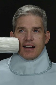
Vertical Angulation
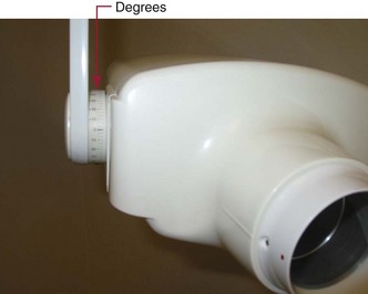
As described in Chapter 18, vertical angulation refers to the positioning of the PID in a vertical, or up-and-down, plane (Figure 19-9). Vertical angulation may be positive or negative and is measured in degrees as viewed on the outside of the tubehead (Figure 19-10). If the PID is positioned above the occlusal plane and the central ray is directed downward, the vertical angulation is termed positive (+). If the PID is positioned below the occlusal plane and the central ray is directed upward, the vertical angulation is termed negative (−).
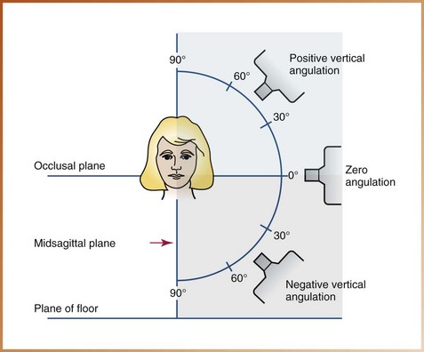
FIGURE 19-9 All vertical angulations above the occlusal plane are termed positive. Vertical angulations below the occlusal plane are termed negative. Zero angulation is achieved when the position-indicating device (PID) and the central ray are parallel to the floor.
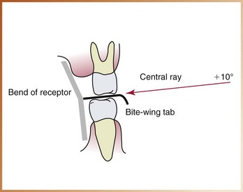
Correct Vertical Angulation: When a bite-wing tab is used, a vertical angulation of +10 degrees is recommended for the bite-wing image. The +10-degree vertical angulation is used to compensate for the slight bend of the upper portion of the receptor and the slight tilt of maxillary teeth (Figure 19-11).
Incorrect Vertical Angulation: Incorrect vertical angulation used in the exposure of a bite-wing results in a distorted image. For example, if a negative vertical angulation is used, the occlusal surfaces of maxillary teeth are evident, and the apical regions of mandibular teeth are seen (Figure 19-12). A bite-wing image exposed with an excessive negative vertical angulation is nondiagnostic.
Rules of Bite-Wing Technique
Five basic rules must be followed when using the bite-wing technique.
1. Receptor placement. The bite-wing receptor must be positioned to cover the prescribed area of teeth to be examined. Specific placements are detailed in the procedures described in the next section.
2. Receptor position. The bite-wing receptor must be positioned parallel to the crowns of both maxillary and mandibular teeth. The receptor must be stabilized when the patient bites on the bite-wing tab or on the bite-wing beam alignment device.
3. Vertical angulation. When a bite-wing tab is used, the central ray of the x-ray beam must be directed at +10 degrees (see Figure 19-6).
4. Horizontal angulation. When a bite-wing tab is used, the central ray of the x-ray beam must be directed through the contact areas between teeth.
5. Receptor exposure. The x-ray beam must be centered on the receptor to ensure that all areas of the receptor are exposed. Failure to center the x-ray beam results in a partial image on the bite-wing receptor or a cone-cut.