Exposure and Technique Errors
After completion of this chapter, the student will be able to do the following:
• Define the key terms associated with exposure and technique errors
• Identify and describe the appearance of the following errors: unexposed receptor, film exposed to light, underexposed receptor, and overexposed receptor
• Describe horizontal and vertical angulation
• Identify and describe the appearances of the following periapical technique errors: incorrect horizontal angulation, incorrect vertical angulation (foreshortened images and elongated images), and incorrect beam alignment (cone-cut images)
• Describe and identify proper receptor placement for bite-wing radiographs
• Identify and describe the appearances of the following bite-wing technique errors: incorrect horizontal angulation, incorrect vertical angulation, and incorrect position-indicating device (PID) alignment (cone-cut images)
• Identify and describe the appearances of the following miscellaneous technique errors: film bending, film creasing, phalangioma, double exposure, movement, and reversed film
While radiographs are taken to benefit the patient, the dental radiographer must remember that only diagnostic images are useful. A diagnostic dental radiograph is one that has been properly placed, exposed, processed, and retrieved; errors in any one of these areas may result in nondiagnostic images. In many instances, nondiagnostic radiographs must be retaken. Retakes result in additional exposure of the patient to ionizing radiation, which is harmful to the patient.
The dental radiographer must have a working knowledge of receptor exposure, technique, and processing errors; processing errors are discussed in Chapter 9. The purpose of this chapter is to describe exposure problems and errors in periapical, bite-wing, and miscellaneous techniques.
Receptor Exposure Errors
Receptor exposure errors that result in nondiagnostic images include unexposed, overexposed, and underexposed receptors, and film that is accidentally exposed to light. All these errors produce images that are too light or too dark. The dental radiographer must be able to recognize exposure errors, identify their causes, and know the necessary steps to correct such problems.
Exposure Problems


Time and Exposure Factor Problems
Underexposed Receptor
Appearance: The image appears light (Figure 20-4).
Periapical Technique Errors
Just as exposure errors may result in nondiagnostic radiographs, errors in technique may also result in nondiagnostic images. Periapical technique errors include problems with receptor placement, angulation, and beam alignment. The dental radiographer must be able to recognize periapical technique errors, identify their causes, and know the necessary steps to correct such problems.
Receptor Placement Problems
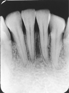
As described in Chapter 16, the periapical image shows the entire tooth, including the apex and surrounding structures (Figure 20-5). For a periapical image to be considered diagnostic, receptor placement must be correct. Specific periapical placements for incisors, canines, premolars, and molars are described in Chapters 17 and 18. Each periapical receptor must be positioned in a certain way to show specific teeth and related anatomic structures. In addition, the edge of the periapical receptor must be placed parallel to the incisal or occlusal surfaces of the teeth and extend one eighth of an inch beyond the incisal or occlusal surfaces.
Incorrect Receptor Placement
A nondiagnostic periapical image may result from improper placement of a receptor over the area of interest, inadequate coverage of the apical regions, or a dropped receptor corner.
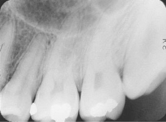
Appearance: No apices are seen on the image (Figure 20-6).
Cause: The receptor was not positioned in the patient’s mouth to cover the apical regions of teeth. As a result, no apical structures appear on the radiograph, and an excessive margin of receptor edge exists (which appears as a black band). This error occurs with both the paralleling technique and the bisecting technique.
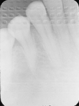
Appearance: The occlusal plane appears tipped or tilted (Figure 20-7).
Cause: The edge of the receptor was not placed parallel to the incisal–occlusal surfaces of teeth. As a result, the occlusal plane appears tipped on the radiograph. If the patient is not instructed to close on the bite block to hold the receptor firmly against the tooth, a corner of the receptor may drop or slip.
Angulation Problems
Angulation is a term used to describe the alignment of the central ray of the x-ray beam in the horizontal and vertical planes. Angulation can be varied by moving the position-indicating device (PID) in either a horizontal or vertical direction. Horizontal angulation refers to the positioning of the PID in a horizontal, or side-to-side, plane. Vertical angulation refers to the positioning of the PID in a vertical, or up-and-down, plane. Correct horizontal and vertical angulations of periapical images are described in Chapter 18.
Incorrect Horizontal Angulation
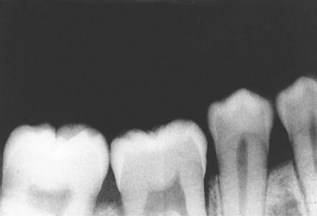
Appearance: Overlapped contacts are seen on the image (Figure 20-8).
Cause: The central ray was not directed through the interproximal spaces. As a result, the proximal surfaces of adjacent teeth appear overlapped in the periapical image. Overlapped contacts prevent examination of the interproximal areas. This error occurs with both the paralleling technique and the bisecting technique.
Incorrect Vertical Angulation
Incorrect vertical angulation results in a radiographic image that is not of the same length as that of the tooth; instead, the image appears either longer or shorter. Elongated or foreshortened images are nondiagnostic.
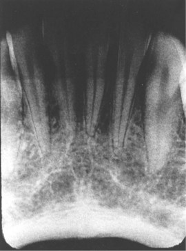
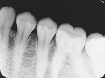
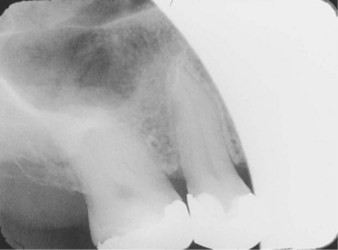
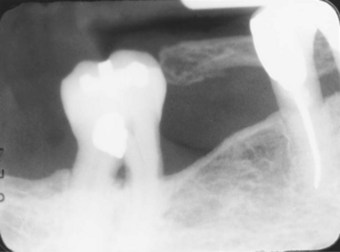
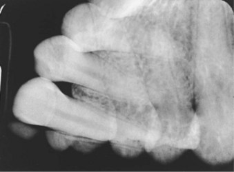
Appearance: Teeth appear short with blunted roots on the image (Figure 20-9).
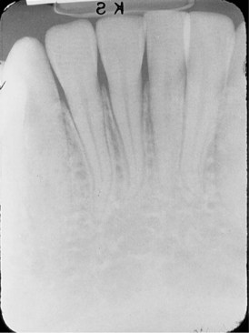
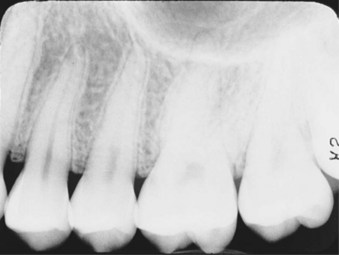
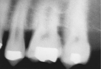
Appearance: Teeth appear long and distorted on the image (Figure 20-10).

Position-Indicating Device (PID) Alignment Problems
If the PID is misaligned and the x-ray beam is not centered over the receptor, a partial image is seen on the resultant radiograph. The PID, or “cone,” is said to “cut” the image. A cone-cut appears as a clear, unexposed area on a dental radiograph and may occur with a rectangular or round PID.
Cone-Cut with Beam Alignment Device
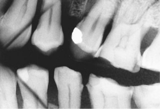
Appearance: A clear (unexposed) area is seen on the image (Figure 20-11).
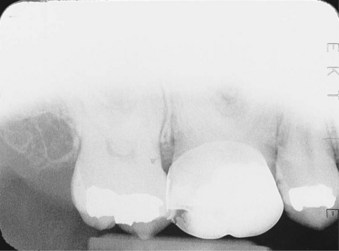
Cause: The PID was not properly aligned with the periapical beam alignment device, and the x-ray beam did not expose the entire receptor. As a result, a clear, unexposed area resembling the outline of the PID is seen on the radiograph.
Correction: To avoid a cone-cut on a periapical receptor when using a beam alignment device, position the PID carefully. If a beam alignment device with an aiming ring is used, make certain that the PID and the aiming ring are aligned. If an aiming ring is not used, make certain that the x-ray beam is centered over the receptor.
Cone-Cut without Beam Alignment Device
Appearance: A clear (unexposed) area is seen on the image (Figure 20-12).
Bite-Wing Technique Errors
Just as errors in the periapical technique may result in nondiagnostic images, errors in the bite-wing technique may also result in images that are nondiagnostic. Bite-wing technique errors include problems with receptor placement, angulation, and beam alignment. The dental radiographer must be able to recognize bite-wing technique errors, identify their causes, and know the necessary steps to correct such problems.
Receptor Placement Problems
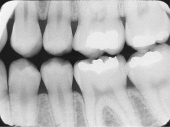
As described in Chapter 19, the bite-wing image includes the crowns of both maxillary and mandibular teeth, the interproximal contact areas, and crestal bone. For a bite-wing image to be considered diagnostic, receptor placement must be correct. Specific bite-wing placements for premolars and molars are described in Chapter 19. In addition to placement over the prescribed areas, the radiograph must show an occlusal plane that is positioned horizontally, along the long axis of the receptor.
Premolar Bite-Wing: The premolar bite-wing must be positioned such that the resulting image shows both maxillary and mandibular premolars and the distal contact areas of both canines (Figure 20-13). To ensure that the distal surfaces of the canines are evident on the resulting radiograph, the receptor must be positioned such that the front edge of the receptor is aligned with the midline of the mandibular canine.
Molar Bite-Wing: The molar bite-wing must be positioned such that the resulting image shows both maxillary and mandibular molars. The molar bite-wing must be centered over the mandibular second molar (Figure 20-14). To ensure correct placement, the receptor must be positioned such that the front edge of the receptor is aligned with the midline of the mandibular second premolar.
Incorrect Receptor Placement
Incorrect bite-wing receptor placement may result in absence of specific teeth or tooth surfaces on an image, a tipped occlusal plane, overlapped interproximal contacts, or a distorted image. Such errors may render a bite-wing image nondiagnostic.
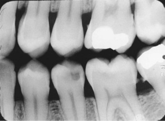
Appearance: The distal surfaces of canines are not visible on the image (Figure 20-15).
Appearance: The third molar regions are not visible on the image (Figure 20-16).
Angulation Problems
To produce diagnostic bite-wing radiographs, the dental radiographer must be prepared to choose the correct horizontal and vertical angulations. Correct horizontal and vertical angulations of bite-wing images are described in Chapter 19. Incorrect horizontal angulation results in overlapped interproximal contacts, and incorrect vertical angulation results in distorted images.
Incorrect Horizontal Angulation
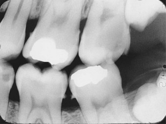
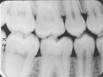
Appearance: Overlapped contacts are seen on the image (Figure 20-17).
Cause: The central ray was not directed through the interproximal spaces. As a result, the proximal surfaces of adjacent teeth appear overlapped in the bite-wing image. Overlapped contacts prevent examination of the interproximal areas.
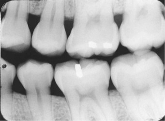
Correction: To avoid overlapped contacts on a bite-wing image, direct the x-ray beam through the interproximal regions. When the contacts are opened, a thin radiolucent line is seen between the proximal surfaces of teeth. The use of Rinn bite-wing instruments minimizes errors in horizontal angulation.
Incorrect Vertical Angulation
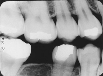
Appearance: Images appear distorted on the radiograph (Figure 20-18).
PID Alignment Problems
As previously described, if the PID is misaligned and the x-ray beam is not centered over the receptor, a partial image, known as a cone-cut, is seen on the bite-wing radiograph.
Cone-Cut with Beam Alignment Device
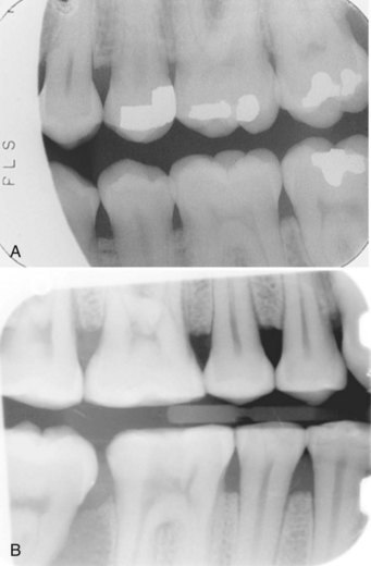
Appearance: A clear (unexposed) area is seen on the image (Figure 20-19, A). A cone-cut can also occur with a rectangular collimator and is seen as a clear area on the image (Figure 20-19, B).
Cone-Cut without Beam Alignment Device
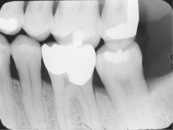
Appearance: A clear (unexposed) area is seen on the image (Figure 20-20).
Miscellaneous Technique Errors
Miscellaneous technique errors, which may be seen on both periapical and bite-wing radiographs, include film bending, film creasing, phalangioma, double exposure, patient movement, and the reversed film. The dental radiographer must be able to recognize these miscellaneous errors, identify their causes, and know the necessary steps to correct such problems.
Film Bending
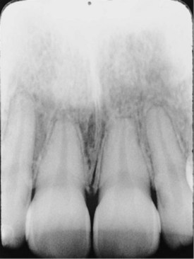
Appearance: Images appear stretched and distorted (Figure 20-21).
Cause: The film was bent excessively because of the curvature of the patient’s hard palate. As a result, stretched and distorted images are seen on the radiograph.
Correction: To avoid film bending, always check film placement before exposure. If the film is bent because of the curvature of the hard palate, cotton rolls can be used with the paralleling technique, or the bisecting technique can be used. Film-holding devices are helpful in preventing film bending.
Film Creasing
Appearance: A thin radiolucent line is seen on the image (Figure 20-22).
Phalangioma
Appearance: An image of the patient’s finger is seen on the radiograph (Figure 20-23).
Cause: The patient’s finger was incorrectly positioned in front of the receptor instead of behind it. As a result, an image of the patient’s finger is seen on the radiograph. The term phalangioma was coined by Dr. David F. Mitchell of the Indiana University School of Dentistry; the term refers to the distal phalanx of the finger whose image is seen in the radiograph. (A phalanx [plural, phalanges] is any bone of a finger or toe.) This error occurs when the finger-holding method is used with the bisecting technique; this technique is not recommended by the authors of this textbook.
Double Exposure
Appearance: A double image is seen on the radiograph (Figure 20-24).
Cause: The same receptor was exposed twice in the patient’s mouth. As a result, a double image is seen on the radiograph. A double exposure is a serious error and necessitates two retakes, one each for the two areas previously radiographed.
Correction: To avoid a double exposure, always separate exposed and unexposed receptors. Once a receptor has been exposed, place it in a designated area (e.g., a disposable cup or bag) away from unexposed receptors. If care is always taken to separate exposed receptors from unexposed receptors, this error will not occur.
Movement
Appearance: Blurred images are seen on the radiograph (Figure 20-25).
Cause: Either the tubehead or the patient moved during the exposure of the receptor. As a result, blurred images are seen on the radiograph.
Correction: To prevent movement errors, stabilize the tubehead and the patient’s head before exposing the receptor, and instruct the patient to remain still. Never expose a receptor when a tubehead is drifting or a patient is moving. Reposition the tubehead, the patient, the receptor, or the PID, as necessary, and then expose the receptor.
Reversed Film
Appearance: Light images with a herringbone pattern are seen on the radiograph (Figure 20-26).
Cause: The film was placed in the mouth backward (reversed) and then exposed. The x-ray beam was attenuated by the lead foil backing in the film packet; consequently, a decreased amount of the x-ray beam exposed the film. As a result, light images with a herringbone pattern (also known as the tire-track pattern) are seen on the radiograph. The herringbone pattern on the radiograph is representative of the actual pattern embossed on the lead foil (see Chapter 7).
Summary
• The dental radiographer must have a working knowledge of exposure technique errors that result in nondiagnostic images. (Processing errors are discussed in Chapter 9.)
• Exposure problems include receptors that are not exposed, accidentally exposed to white light, overexposed, or underexposed. All these errors produce nondiagnostic radiographs that are too light or too dark.
• Periapical and bite-wing technique errors include receptor placement, angulation, and PID alignment problems.
• Miscellaneous technique errors include film bending, film creasing, phalangioma, double exposure, patient movement, and the reversed film.
• The dental radiographer must be able to recognize and identify the causes of exposure technique errors. In addition, the dental radiographer must know the necessary steps to correct such errors.
Haring, JI, Lind, LJ. Film exposure, processing and technique errors. In: Radiographic interpretation for the dental hygienist. Philadelphia: Saunders; 1993.
Johnson, ON, Thomson, EM, Identifying and correcting faulty radiographs. Essentials of dental radiography for dental assistants and hygienists, ed 8, Upper Saddle River, NJ, Pearson, 2007.
Miles, DA, Van Dis, ML, Razmus, TF. Intraoral radiographic techniques. In: Basic principles of oral and maxillofacial radiology. Philadelphia: Saunders; 1992.
Miles, DA, Van Dis, ML, Williamson, GF, Jensen, CW, Technique/processing errors and troubleshooting. Radiographic imaging for the dental team, ed 4, St. Louis, Saunders, 2009.
White, SC, Pharoah, MJ, Processing x-ray film. Oral radiology: Principles and interpretation, ed 6, St. Louis, Mosby, 2009.
Identification
For questions 1 to 10, refer to Figures 20-27 through 20-36. Identify the exposure technique error seen in each radiograph.
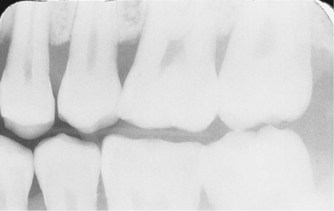
FIGURE 20-27
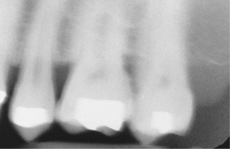
FIGURE 20-28
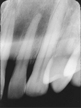
FIGURE 20-29
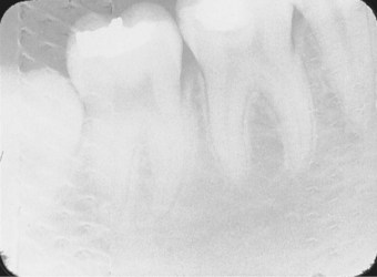
FIGURE 20-30
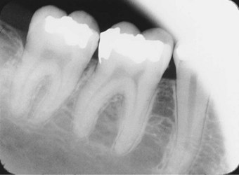
FIGURE 20-31
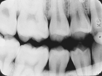
FIGURE 20-32
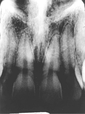
FIGURE 20-33
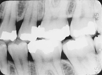
FIGURE 20-34
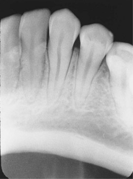
FIGURE 20-35
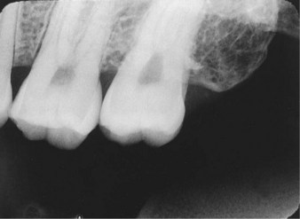
FIGURE 20-36
1. _____________________________________________
2. _____________________________________________
3. _____________________________________________
4. _____________________________________________
5. _____________________________________________
6. _____________________________________________
7. _____________________________________________
8. _____________________________________________
Multiple Choice
________ 16. Too much vertical angulation results in images that are:
________ 17. Too little vertical angulation results in images that are:
________ 18. Incorrect horizontal angulation results in images that are:
________ 19. Which of the following errors can occur with the bite-wing technique?
________ 20. Which of the following errors can occur with the bisecting technique?