Casting and Soldering Procedures
Casting is the process by which a wax pattern of a restoration is converted to a replicate in a dental alloy. The casting process is used to make dental restorations such as inlays, onlays, crowns, bridges, and removable partial dentures. Because castings must meet stringent dimensional requirements, the casting process is extremely demanding. In dentistry, virtually all casting is done using some form or adaptation of the lost-wax technique. The lost-wax technique has been used for centuries, but its use in dentistry was not common until 1907, when W.H. Taggart introduced his technique with the casting machine.
Soldering is a method of joining two or more cast or wrought pieces using another alloy called a solder. Like casting, soldering in dentistry must ensure that the dimensions of soldered pieces are maintained to a high degree of accuracy. Casting and soldering techniques use many of the same laboratory equipment and materials.
This chapter will discuss casting and soldering techniques. These techniques use several materials that are discussed in detail in other chapters. Alloys for casting have been previously discussed in Chapters 15 and 16. Die materials and investments have been discussed in Chapter 13, and waxes in Chapter 14. This chapter will focus on techniques used to work with these materials, beginning with an overview of the lost-wax casting process, then reviewing each step in this process: waxing, spruing, investing, burnout, and casting. Finally, some general considerations for dental soldering will be presented. The techniques of casting and soldering are complex and vary considerably for different alloy types, and this chapter is not intended to be a comprehensive discussion of these techniques. For further details, the reader is referred to books on casting and soldering techniques in the dental and metallurgical literature.
CASTING
The lost-wax technique is so named because a wax pattern of a restoration is invested in a ceramic material, then the pattern is burned out (“lost”) to create a space into which molten metal is placed or cast. The entire lost-wax casting process is diagrammed in Fig. 17-1. A wax pattern is first formed on a die of the tooth to be restored or, occasionally, directly on the tooth. All aspects of the final restoration are incorporated into the wax pattern, including the occlusion, proximal contacts, and marginal fit. Once the wax pattern is completed, a sprue is attached, which serves as a channel for the molten metal to pass from the crucible into the restoration. Next, the pattern and sprue are invested in a ceramic material, and the invested pattern is heated until all remnants of the wax are burned away. After burnout, molten metal is cast into the void created by the wax pattern and sprue. Once the investment is broken away, the rough casting is pickled to removed oxides. Finally, the sprue is removed and the casting is polished and delivered to the patient. If all steps have been done well, the final restoration will require minimal modification during cementation into the patient’s mouth.
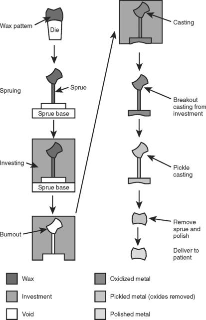
FIGURE 17-1 The lost-wax casting process. A wax pattern of the final restoration is made on a die (a replicate of the prepared tooth). A sprue is attached, and the wax pattern is removed from the die and attached to a sprue base and casting ring. The sprue and pattern are invested and the sprue base is removed. The casting ring is placed in an oven to burn out the wax (hence, the term lost wax). Metal is melted and cast into the void in the investment created by the wax pattern. After the metal has solidified, the investment is removed and the casting pickled to remove oxides. Finally, the sprue is removed and the casting is polished, cleaned, and delivered to the patient. Note the angles on the sprue base should be rounded.
Dimensional Changes in the Lost-Wax Technique
If materials used during the casting process didn’t shrink or expand, the size of the final cast restoration would be the same as the original wax pattern. However, dimensional changes occur in most of the steps in Fig. 17-1 and, in practice, the final restoration may not be exactly the same size as the pattern. The management of these dimensional changes is complex, but can be summarized by the equation:
wax shrinkage + metal shrinkage = wax expansion + setting expansion + hygroscopic expansion + thermal expansion
This equation balances the shrinkage (left side of equation) against the expansion (right side of equation) that occurs during the casting process. If the final restoration is to fit the die, the shrinkage and expansion during the casting process must be equal.
Shrinkage forces in the casting process come from two sources: wax and metal. Although the die restricts the wax from shrinking to a large degree while the pattern is on the die, residual stresses may be incorporated into the pattern and released during investing, when the pattern is removed from the die. Furthermore, if the investing is done at a temperature lower than that at which the wax pattern was formed, the wax will shrink significantly because of the high coefficient of thermal expansion of waxes (see Chapter 14). Metal shrinkage occurs when the molten metal solidifies, but this shrinkage is normally compensated by introducing more metal as the casting solidifies. However, once the entire casting has reached the solidus temperature of the alloy, shrinkage will occur as the casting cools to room temperature. As for wax, the metallic shrinkage that occurs below the solidus is caused by the coefficient of thermal expansion for the alloy. Cooling shrinkage may reach 2.5% for an alloy that cools from a high solidus temperature (1300° to 1400° C), depending on the coefficient of thermal expansion of the alloy. A typical shrinkage range for most alloys is 1.25% to 2.5%. Furthermore, because the casting is solid at this point, the only possible compensation mechanism is to start with a void space that is 1.25% to 2.5% too large. Thus, shrinkage of wax and metal must be compensated with expansion in the investment if the casting is to have the appropriate dimensions. Figure 17-2 shows a casting that was too small because of inadequate compensation of the solidification shrinkage of the alloy.
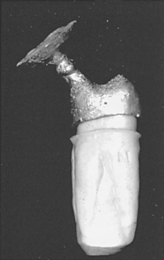
FIGURE 17-2 A casting that is too small and will not seat on the tooth because there was inadequate compensation of solidification shrinkage of the alloy. As the picture shows, the degree of misfit can be substantial. (Courtesy Dr. Carl W. Fairhurst, Medical College of Georgia School of Dentistry.)
Sources for expansion of the investment are listed in the equation previously presented and come from two sources: expansion of the wax pattern or expansion of the investment itself. Investment expansion may be setting, hygroscopic, or thermal; these phenomena are discussed in detail in Chapter 13. The relative contributions of these three expansions are not important as long as the total expansion is sufficient to balance the shrinkage of metal previously discussed. Expansion of the wax pattern before investing is theoretically possible, but impractical because of the release of residual stresses that distort the pattern (see Chapter 14). Thus, in the shrinkage-expansion equation, the primary shrinkage comes from cooling of the solidified casting, and this shrinkage must be compensated by an appropriate total expansion of the investment.
Accuracy of the Lost-Wax Technique
A casting should be as accurate as possible, although a tolerance of ±0.05% for an inlay casting is acceptable. If the linear dimension of an average dental inlay casting is assumed to be 4 mm, ±0.05% of this value is equal to only ±2 μm, which suggests that if two castings made for the same tooth have a variation of 4 μm, the difference may not be noticeable. To visualize this dimension, recall that the thickness of an average human hair is about 40 μm. Therefore, the tolerance limits of a dental casting are approximately one tenth the thickness of a human hair. To obtain castings with such small tolerance limits, rigid requirements must be placed not only on the investment material but also on the impression materials, waxes, and die materials. Naturally, technical procedures and the proper handling of these materials are equally important. The values for the setting, hygroscopic, and thermal expansions of investment materials may vary from one product to another, and slightly different techniques may be used with different investments. In each case, the values obtained for any one property should be reproducible from one batch to another and from one casting to another.
FORMATION OF THE WAX PATTERN
The fabrication of a restoration in wax is convenient because it involves few materials and is inexpensive, fast, reversible, and customizable. However, the properties of wax, such as its high coefficient of thermal expansion and tendency to flow and harbor residual stresses, must be kept in mind. These properties are reviewed in detail in Chapter 14. Failure to accommodate for these properties will result in inaccurate castings. There are two fundamental ways to prepare a wax pattern for a dental restoration. In the direct method, the pattern is prepared on the tooth in the mouth. This method can only be used for small inlay restorations. In the indirect method, a model (die) of the tooth is first made, and the pattern is made on the die. The indirect method is used for all types of restorations. Each of these techniques will be discussed at length.
Direct Wax Patterns
As mentioned in Chapter 14, the wax for a direct wax pattern must be heated sufficiently to have adequate flow and plasticity under compression to reproduce all details of the cavity walls. Adequate compression of the wax is required in forming direct wax patterns. Also, overheating of the wax should be avoided because of possible tissue damage and discomfort to the patient, as well as the difficulty encountered in compression of very fluid wax when it is overheated.
When wax is heated to the proper working temperature of approximately 50° to 52° C for a short period, the previously induced stress from manufacturing and handling tends to be dissipated. A stress-free piece of wax at the proper consistency should be obtained so that the pattern, when formed under pressure, remains relatively stress free. Thus, minimal distortion results when the pattern is subsequently removed from the tooth. This heating and annealing of the wax before insertion into the cavity preparation are accomplished most easily and effectively in a small dry-heat oven. A nonuniform consistency and possible volatilization of some of the wax mass tend to result from excessively heating the wax over a Bunsen burner flame. Although wax may be annealed in water that is at a proper temperature, it should not be stored for long periods under these conditions. Prolonged heating of the wax in water, especially at high temperatures, may result in a crumbly mass.
Because wax has a rather low thermal conductivity, cooling from the working temperature to mouth temperature occurs slowly, and ample time for cooling should be allowed. The decrease in temperature of the wax to mouth temperature results in a contraction. This contraction is offset to some degree when the pattern is held under pressure until mouth temperature is reached, because the compression stresses tend to be released, to some degree, when the wax is removed from the prepared tooth. However, the degree and distribution of these stresses vary from one pattern to another. Although these induced stresses are undesirable, their presence is unavoidable.
Because carving a wax pattern directly in the mouth demands a high degree of dexterity, any property that makes manipulation easier is desirable. Therefore, ANSI/ADA Specification No. 4 (ISO 15854) for inlay wax states that the wax color should contrast with the hard and soft tissues of the mouth; the wax should soften without becoming flaky; and the wax should not show appreciable chipping or flaking when trimmed to a fine margin. Carving instruments that have been sufficiently warmed are desirable to soften, but not melt, the wax as the marginal adaptation and contour are developed. The warm instrument brings the portion of the wax that is being manipulated to its proper working temperature, so that less stress is induced in these areas. A cool carving instrument burnishing over or cutting through the wax introduces tensile and compressive stresses into the pattern, which are detrimental to the ultimate fit of the casting.
Indirect Wax Patterns
When a wax pattern is formed by the indirect method, a metal or stone die is used, which is the positive replica of the prepared tooth and at least some of its surrounding structure. This tooth replica permits the pattern to be formed outside the mouth. Forming the wax pattern on a die permits a change in the type of wax and certain manipulative procedures that are necessary for the direct technique. The convenience provided by the indirect method makes the property of wax flow less critical, because the pattern may be removed from the die at a lower temperature and with greater ease.
Some laboratories will coat the die with a die spacer on stone dies to allow space for the cement in the final restoration. The spacer is brushed onto the die as a viscous liquid, then allowed to dry before applying wax lubricant and wax. The thickness of the spacer, which can be difficult to control, ranges from 10 to 30 μm and is a function of the manipulative technique. Die spacers should not be used to compensate for improper manipulation of the other materials in the casting process, nor should they be used on the margins of the restoration.
When adapting wax to stone or some metal dies, some form of lubricant must be used to release the wax pattern from the die. In the mouth no such lubricant is required because a thin film of saliva or dentinal fluid serves as a lubricant. A variety of fluids is currently available to prevent the attachment of the wax to the die. These fluids produce a separator film of minimum thickness. An excess of separator is to be avoided because it leads to inaccuracies in the wax pattern and a poor surface of the cast alloy.
The wax may be adapted to the die either by flowing small melted increments from a spatula to build up the desired contour or by the compression method, as is suggested in the direct technique. By either method the temperature of a stone die is of little concern in wax adaptation because the stone is a poor thermal conductor. Likewise, the temperature of a metal die is not critical when compression of the wax is used to form the pattern. However, this temperature is critical when molten increments are used to build up the pattern because the manner of solidification of the wax depends on the temperature of the metal die.
When molten wax flows onto a cool metal die, the wax immediately adjacent to the die solidifies rapidly because the heat from the molten wax is rapidly dissipated. The wax adjacent to the air stays molten for a period; as it solidifies and contracts, it pulls the previously congealed wax away from the metal, as shown in Fig. 17-3, A. Conversely, if the metal die is warmed throughout to near body temperature, the wax solidifies more evenly throughout its mass, resulting in better adaptation, as shown in Fig. 17-3, B. The die can be warmed by placing it under an electric lamp or with the carving instruments on an electric heating pad at a suitable temperature. The indirect wax pattern is carved with a warm instrument, as is the direct pattern, again to minimize the formation of stresses in the wax.

FIGURE 17-3 Improper manipulation of the wax pattern can cause the pattern to distort significantly. A, The wax was cooled too quickly and residual stresses have been released, causing the pattern to pull away from the die. B, A proper cooling rate and manipulation results in a pattern that remains adapted to the die.
Because of the basic physical nature of wax, distortion of the pattern is a continual hazard. Not only does wax have one of the highest coefficients of thermal expansion of any dental material, it also possesses a relatively low softening temperature, which may cause stress release or flow to occur. Stresses are easily induced in forming any pattern; in fact, the formation of a completely stress-free wax pattern would appear improbable. However, with knowledge of the physical characteristics of the wax, an operator can minimize the stresses in the pattern by applying the appropriate manipulative procedures.
SPRUING THE WAX PATTERN
The purpose of the sprue is to provide a conduit for the molten metal to reach the void formed by the wax pattern after burnout. Proper spruing technique and sprue design are critical to the successful casting of the restoration. Before spruing, the wax pattern is generally briefly removed from the die. After the die is cleaned and relubricated, the pattern is replaced on the die and the margins of the restoration are finalized. The type, number, location of attachment, diameter, length, and direction of the sprues are all important to the success of the casting.
Several types of materials are used for sprues, depending on the type of restoration being cast. For small inlays, a hollow-metal sprue may be used. The metal is stronger than a comparably sized wax sprue. The core of the hollow pin should be filled with sticky wax to preclude sucking of the pattern wax into the sprue when attaching the sprue to the pattern. Of course, the metallic sprue cannot be burned out, but must be carefully removed after investing of the pattern. Round wax is a commonly used sprue material for many restorations of all sizes. Wax has the advantages of being inexpensive, easy to manipulate, easy to burn out, and available in a variety of diameters. Wax sprues can also be easily designed for complex castings that require multiple sprues and vents. Plastic sprues have also been used for casting. Plastic has the rigidity of metal, an advantage, but can still be burned out, although longer burnout times may be required than with wax.
For most common crowns and inlays, a single sprue is sufficient. However, bridges and removable partial dentures may require multiple sprues in a complex configuration (Fig. 17-4). Sprues of small diameter may also be attached to the pattern to act as vents to enhance the displacement of gases from the mold during the entry of the molten metal. Two sprues in the configuration of a “Y” may also be used on some relatively small restorations to prevent warpage of the wax pattern susceptible to distortion. The Y-sprue design is often used on MOD inlay restorations.
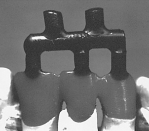
FIGURE 17-4 A complex sprue design for a three-unit fixed partial denture. The restoration is on the bottom (lighter colored wax). Each unit has a sprue feeding to it from a horizontal feeder bar. Two large diameter sprues feed into the feeder bar; to encourage turbulence of the molten metal, they are purposely not aligned with the unit sprues. The use of complex arrangements such as this ensures that the molten metal will cause the sprue bar area to become hotter and freeze last. Note that the attachments of the sprues to the individual units are broad and flared. (Courtesy Carl W. Fairhurst, Medical College of Georgia School of Dentistry.)
The location of the sprue attachment to the wax pattern is paramount for proper casting. In general, the sprue should be attached to the bulkiest portion of the wax pattern, as shown in Fig. 17-5. Placing the sprue away from the fine margins minimizes distortion of this delicate area of the pattern. When attaching the sprue, the point of contact should be flared, as shown in insert x of Fig. 17-5, B. This allows more even flow of the metal into the mold and less porosity in the casting at the point of contact. In addition, not flaring the sprue connections, as shown in insert y, results in the formation of sharp projections of investment that can break off and incorporate into the metal during casting. The direction of the sprue is another factor to consider. In general, the sprue should be directed toward the margins such that it minimizes the turbulence of the flow of the molten metal and favors the fine margins of the wax pattern. Finally, the point of attachment of the sprue should be selected, keeping in mind that the contour of the restoration will be altered by the sprue’s presence. Although the contour can be restored once the casting is complete, such recontouring is often much more difficult in metal.
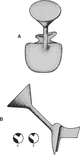
FIGURE 17-5 Diagram showing the position and area of attachment of a single sprue to a small inlay restoration pattern. The location (A), diameter, length, and angle of the sprue (B) are critical to preserving the proper freezing order during casting. Furthermore, the attachment of the sprue to the restoration is critical. In x, the sprue is attached with rounded corners to avoid turbulence and the risk of invest-ment fracture. In y, the sharp corners of attachment are not desirable.
The diameter of the sprue, in conjunction with the pressure of the casting machine and density of the molten metal, controls the rate of flow of the molten metal into the mold cavity. The larger the diameter of the sprue and the higher the density of the molten metal, the faster the molten metal should enter the mold cavity. However, the mold cavity is filled with various gases before the entry of the molten metal, and the mold cavity cannot be filled completely unless all gases are driven out through the pores of the investment. As mentioned in Chapter 13, a requirement of dental investments is that they be sufficiently porous to allow gases to escape. Thus, not only do the sprue diameter and pressure of the casting machine have an effect on the rate of filling the mold cavity, but the rate of elimination of gases from the mold cavity also has an effect. Incomplete castings may result from using a sprue with a diameter that is too small. In this case, the molten metal may solidify in the sprue area before completely filling the mold cavity. The proper sprue diameter for dental castings, depending on the size of the wax pattern, may vary between 6 and 12 gauge (4.1 and 2.0 mm, respectively). Theoretically, the diameter of the sprue should be larger than the thickest part of the wax pattern; however, practically it could be slightly smaller.
The length of the sprue is also important to ensure a good casting. The wax pattern should be positioned approximately 6 mm from the end of the casting ring (Fig. 17-6). This position provides sufficient thickness of investment to contain the molten metal and reduces the amount of investment through which gases must escape. Positioning the pattern close to the surface also ensures that the casting cools more rapidly than the more centrally located sprue. When this is done, the metal in the sprue remains liquid and flows to the casting until the casting is completely solidified.
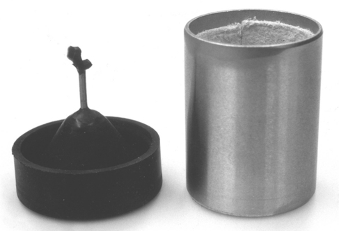
FIGURE 17-6 Picture of an inlay restoration on a single sprue pin (left). The single sprue pin is attached to the sprue base. Next, the casting ring lined with a ceramic paper (right) will be placed onto the sprue base and the pattern will be invested. Once the investment has set, the metallic sprue pin will be removed before burnout of the pattern.
Once the sprue is attached to the restoration, the other end of the sprue is attached to a sprue base usually made of hard rubber (see Fig. 17-6). As with the attachment of the sprue to the restoration, the base-sprue attachment should avoid sharp corners to ensure smooth, nonturbulent flow of the metal into the pattern during casting. Sharp corners may also encourage fracture of pieces of the investment during casting, sending these pieces of investment into the mold and possibly the restoration. Once the pattern has been completely sprued on the base, it is ready for investing.
INVESTING THE WAX PATTERN
Investing is the process by which the sprued wax pattern is embedded in a material called an investment. The investment must be able to withstand the heat and forces of casting, yet must conform to the pattern in a way such that the size and surface detail are exactly reproduced. In dentistry, gypsum- and phosphate-bonded investment materials are the two types of materials used for this purpose; details about the composition, setting reaction, and expansion properties of these materials are covered in Chapter 13. After spruing, the pattern appears as shown in Fig. 17-6 (left). A casting ring is added to contain the investment while the investment material is poured carefully around the pattern.
For the setting and hygroscopic expansion of an investment to take place more uniformly, some allowance must be made for the lateral expansion of the investment. Solid rings do not permit the investment to expand laterally during the setting and hygroscopic expansions of the mold. To overcome this lateral restriction, a ceramic paper liner is placed inside the ring. A drawing of the sprue base, wax pattern, inlay ring, and liner in position is shown in Fig. 17-7. The ceramic paper liner is cut to fit the inside of the metal ring and is held in place with the finger. The ring containing the liner is then dipped into water until the liner is completely wet and water is dripping from it. The ring is shaken gently to remove the excess water. After the liner has been soaked, it should not be touched or adapted further with a finger because this reduces its cushioning effect, which is needed for the lateral expansion of the investment. A liner that is about 3 mm short at each end of the ring is preferred. When the liner is equally short at each end of the ring, the investment is locked into the ring, and uniform expansion of the cavity form occurs.
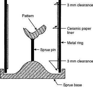
FIGURE 17-7 Cross-sectional diagram of the assembled sprue-based and metal casting ring shown in Fig. 17-6. A single sprue connects the sprue base to the inlay pattern. After investing but before burnout, this metallic sprue pin will be removed. If the sprue is made of wax, its removal is not necessary. The ceramic liner is 3 mm short of the top and bottom of the ring to lock in the investment during burnout and casting.
During investing, the water-based gypsum material must flow around the pattern and capture every surface detail. However, the wax surfaces generally are not easily wetted by water. The surface of a wax pattern that is not completely wetted with investment results in surface irregularities in the casting that destroy its accuracy. These irregularities can be minimized by applying a surface-active wetting agent on the wax. The function of the wetting agent is to reduce the contact angle of a liquid with the wax surface. Wetting agents also remove any oily film that is left on the wax pattern from the separating medium. The spreading of water is illustrated by the comparison in Fig. 17-8, which shows silhouettes of advancing water droplets on a polished inlay wax surface, A, and on the same surface treated with the surface-active agent before the water droplet was applied, B. In B, the agent was applied and blotted dry with lens paper. The contact angles are 98 degrees for the plain wax surface and 61 degrees for the treated wax surface. The lower contact angle indicates that the treated wax surface has an affinity for water, which results in the investment being able to spread more easily over the wax. Because the surface-active agents are quite soluble, rinsing the wax pattern with water after the application defeats the purpose of their use, as shown in Fig. 17-8, C. The same wax as was used in Fig. 17-8, B, was rinsed with tap water and blotted dry. The contact angle in this case was 91 degrees, closely approaching that of the original untreated wax surface.
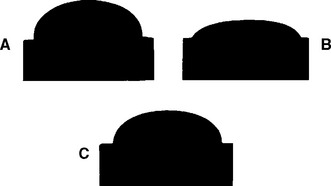
FIGURE 17-8 Diagram illustrating the contact angle of a liquid like water on the wax pattern. In A, the water has a high contact angle and does not wet the wax well. In B, a wetting agent was applied, which decreases the contact angle and improves the wetting. In C, the contact angle is increased again because the wetting agent was rinsed off. For successful investing, the water-based investment must wet the wax pattern well.
The distortion of the wax pattern after its removal from the die is a function of the temperature and time interval before investing. The nearer the room temperature approaches the softening point of the wax, the more readily internal stresses are released. Also, the longer a pattern is allowed to stand before investing, the greater the deformation that may occur, even at room temperature. A pattern should therefore be invested as soon as possible after it is removed from the die, and it should not be subjected to a warm environment during this interval. In any case, a pattern should not stand for more than 20 to 30 minutes before being invested. Once it is properly invested and the investment has set, there is no danger of further pattern distortion, even if it remains for some hours before the final stages of wax elimination (burnout) and casting.
Investment Techniques
During investing of the pattern, the correct water/powder ratio of the investment mix, a required number of spatulation turns, and a proper investing technique are essential to obtain acceptable casting results. The two methods of investing the wax pattern are hand investing and vacuum investing. In both cases, the proper amount of investment powder and water should be used, following the manufacturer’s instructions exactly. The water is added first, followed by the slow addition of the powder to encourage the removal of air from the powder. The powder and liquid are mixed briefly with a plaster spatula until all the powder is wetted.
In hand investing, the cover of the bowl containing the investment mix is placed over the bowl (Fig. 17-9). The cover contains a mechanical mixer, and the mixing is done by hand, usually for 100 turns of the spatulator. The setting rate of an investment depends on the number of spatulation turns, which also affects the hygroscopic expansion. The investment, after being spatulated, is placed on the vibrator to eliminate some of the air bubbles from the mix and to collect all the mix from the sides of the rubber bowl into the center. The sprue base, which holds the sprue and wax pattern, is held with one hand, and the investment is painted over the wax pattern with a camel-hair brush. In painting the pattern, the investment should be teased ahead of the brush to prevent incorporation of air adjacent to the pattern. Furthermore, to avoid distorting the pattern, the brush itself should not touch the pattern. After the painting is completed, the pattern is vibrated very gently with the sprue base held firmly with the fingers and the underside of the hand resting on the vibrator. This method relieves any minor air bubbles that might have been trapped around the wax pattern.
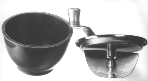
FIGURE 17-9 A device for hand mixing investment. The hand mechanical spatula is placed over the bowl and the investment is then mixed before pouring it into the casting ring.
After the pattern has been painted with investment, the mixed investment is poured into the ring, which is held at a slight angle so the investment flows slowly down its side to fill from the bottom to the top. In this manner, the possibility of trapping air in the ring or around the pattern is reduced to a minimum. It is often helpful to hold the assembled ring and the sprue base in one hand, which rests gently on a vibrator, while the investment is being poured into the ring. When the ring is completely filled, it is leveled with the top by the edge of a plaster spatula. The filled ring is then set aside for the investment to set completely, which usually requires 45 to 60 minutes. When a phosphate-bonded investment is used, the ring is slightly overfilled, the top of the ring is not leveled off, and the investment is allowed to set. After the investment has set, the excess investment is ground off using a model trimmer. This procedure is necessary because a nonporous, glassy surface results, which must be ground off to improve the permeability of the investment and allow for gases to readily escape from the mold during casting.
In vacuum investing, special equipment is used to facilitate the investing operation. A popular vacuum machine used in dentistry is shown in Fig. 17-10. With this equipment, the powder and water (or special liquid) are mixed under vacuum and the mixed investment is permitted to flow into the ring and around the wax pattern with the vacuum present. Although vacuum investing does not remove all the air from the investment and the ring, the amount of air is usually reduced enough to obtain a smooth adaptation of the investment to the pattern. Vacuum investing often yields castings with improved surfaces when compared with castings produced from hand-invested patterns. The degree of difference between the two procedures depends largely on the care used in hand investing. Whether hand- or vacuum-investing procedures are used in filling the casting ring, the investment should be allowed to harden in air before burnout of the wax.
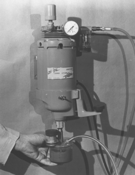
FIGURE 17-10 A powered vacuum unit for investing. The investment powder and liquid are added to the mixing bowl and mixed with a spatula to ensure wetting of the powder. A vacuum line is then attached to the mixing bowl and the top of the power unit. The casting ring is inverted and attached to the mixing container. The power is switched on, and the mixing bowl is attached to the bottom of the mixer, causing the mixing blades to rotate in the bowl. After mixing 10 to 15 seconds, the mixing bowl is inverted such that the investment slowly enters the casting ring. Vibration is applied by the lever protruding from the right side of the mixer. Alternatively, the mixer may be removed from the mixing bowl after mixing and the investment poured by hand into the ring.
BURNOUT OF THE WAX PATTERN
After the wax pattern has been invested, it should be set aside until the investment has hardened, usually 45 to 60 minutes. The metallic ring is placed directly into the burnout oven to begin eliminating wax from the mold. As discussed previously, investment must withstand the impact force exerted by the molten metal when it enters the hot mold during casting. These forces can be considerable. The metallic ring will support the investment as the molten metal enters the mold (Fig. 17-11). In spite of the support given by the ring, it is imperative that the investment be mixed properly and allowed to set completely so it will obtain a sufficient strength.
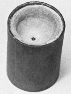
FIGURE 17-11 A casting ring that has been filled with investment, before burnout. The wax sprue is visible as a small dark dot in the middle of the investment. The casting ring is inverted and the sprue base has been removed. This ring is ready for burnout.
During burnout, the mold is placed in an oven to completely eliminate the wax, thereby forming a cavity into which the molten metal is cast. During wax elimination, the investment expands thermally, which is necessary to compensate for the casting shrinkage. Although wax melts at a comparatively low temperature, its complete elimination requires much higher temperatures. Usually, if elimination is not complete, small bits of the wax residue are retained in the fine margins of the mold and prevent the formation of a complete casting. When the molten metal enters the sprue hole, the resulting force causes the air in the mold cavity to be driven out through the pores of the investment, thus the mold cavity is filled completely. This process takes less than a second. The presence of any foreign material in the mold cavity slows or possibly prevents the air or other gases from being driven out of the mold before the molten metal solidifies. As a result, the castings may be incomplete or the margins irregular, in which case the casting should be repeated, starting with a new wax pattern.
Because waxes are organic materials, they are composed of carbon, hydrogen, oxygen, and nitrogen. When heated to higher temperatures, any organic material decomposes and forms carbon dioxide (CO2), water (H2O), or nitrogen oxide (NO2), all of which are gases and can be easily eliminated. However, formation of these gases depends on the presence of a sufficient supply of oxygen, the relatively high temperature of the oven, and adequate heating time of the ring. If insufficient oxygen is available to the wax in the mold cavity, the temperature of the oven is not high enough, or the wax pattern is heated for only a short time, incomplete reaction between the wax and oxygen may result. The internal walls of mold cavities placed in a room-temperature oven, set at 500° C, and left for different times are shown in Fig. 17-12. The longer the ring remained in the oven, the better the elimination of carbon residue from the mold cavity. Castings made under these four conditions showed that for conditions seen in Fig. 17-12, A and B, the castings were not complete, and part of the pattern did not cast. For the condition seen in Fig. 17-12, C, depending on the total amount of wax used, the number of investment rings in the oven at the same time, and other such variables, the castings were either incomplete (as shown in A and B) or appeared complete but had short and rounded margins. These results indicated that elimination of gases from mold cavities was rather slow because of the presence of carbon deposits, and the molten alloy solidified before all the gases around the marginal area could escape. For all three conditions, the surfaces of the castings were black and could not be cleaned by normal pickling (deoxidization) action. This black color indicated that the surfaces were covered with fine particles of carbon residue, because the acid in pickling solutions is not effective in dissolving or removing carbon particles. Castings made under the condition shown in Fig. 17-12, D, were complete, with sharp margins, and on pickling the casting surfaces had a typical yellow color. These experiments demonstrate the importance of adequate burnout time.
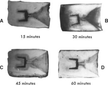
FIGURE 17-12 Effect of burnout time of wax in investment molds on the presence of carbon residue. Each mold was placed in a room-temperature furnace that was then set at 500° C, heated for the times indicated (A to D), and sectioned to examine the internal appearance. Notice the dark gray area of carbon residue around the mold cavity in C even after 45 minutes of heating.
A satisfactory way of eliminating the wax pattern is to set the mold in the furnace with the sprue hole placed downward at first, so most of the wax drains out and is eliminated as a liquid. The ring is then inverted with the sprue hole placed upward. In this position the oxygen in the oven atmosphere can circulate more readily into the cavity, react with the wax, and form gases rather than the fine carbon that interferes with the venting of the mold cavity. The lower the mold temperature and larger the wax pattern, the longer the mold should be left in the oven. For a 500° C oven temperature and larger wax patterns, the mold should remain in the oven for approximately 1 hour, with the sprue hole placed downward during half of this time and upward during the other half. If more than one ring is placed in an oven, a longer period is required for wax elimination. The general rule is to add 5 minutes to the burnout time for every extra ring placed in the oven at 500° C. With an oven temperature of 600° to 700° C, a shorter time may be sufficient to completely eliminate the wax.
Investment materials are poor heat conductors, which results in a temperature difference between the inner core and the outside portion of the mold. Although this difference is relatively great at the beginning of the burnout, it diminishes as time progresses and is zero at the time of casting. The difference in temperature between the inner and outer portions of the mold are even greater if the mold is placed in a hot oven or if the heating rate of the oven is too rapid. The outside of the mold, being exposed to a higher temperature, expands somewhat more than does the inner part. This expansion may cause the mold to crack during heating. Because of the high thermal expansion of investments containing cristobalite, these temperature differences may be especially important. For best results, this type of investment should always be placed into a room-temperature oven and the oven temperature increased slowly. These temperature differences do not affect quartz-containing investments, probably because their rate of thermal expansion is slower than that of cristobalite investments.
When the wax pattern is completely eliminated and the mold has reached the casting temperature, the gold alloy is melted by an appropriate method and cast into the mold cavity immediately upon removal of the mold from the burnout oven. However, the investment should never be allowed to cool before casting because the expansion of the investment during burnout is essentially irreversible (see Chapter 13). If the mold cools before it is cast, the only recourse is to discard the mold and start over by making a new wax pattern.
CASTING PROCEDURE
Several types and designs of casting machines are used to make dental castings. All casting machines accelerate the molten metal into the mold either by centrifugal force or air pressure. Numerous modifications and variations of these methods are used in different machines. The selection of the casting and melting techniques is heavily influenced by the type of alloy and restoration to be cast.
A variety of centrifugal machines are available. Some spin the mold in a plane parallel to the table top on which the machine is mounted, whereas others rotate in a plane vertical to the table top. Some are spring-driven, and others are operated by electric power. An electric heating unit is attached to some machines to melt the alloys before spinning the mold to throw in the metal. Others have a refractory crucible in which the alloy is melted by a torch before the casting operation is completed. Each of these machines depends on the centrifugal force applied to the molten metal to cause it to completely fill the mold with properly melted metal (Fig. 17-13). Concerning the quality of the casting, a preference for either machine is not known. The main advantage of the centrifugal machines is the simplicity of design and operation, with the opportunity to cast both large and small castings on the same machine. Typical examples of centrifugal machines are shown in Fig. 17-14.
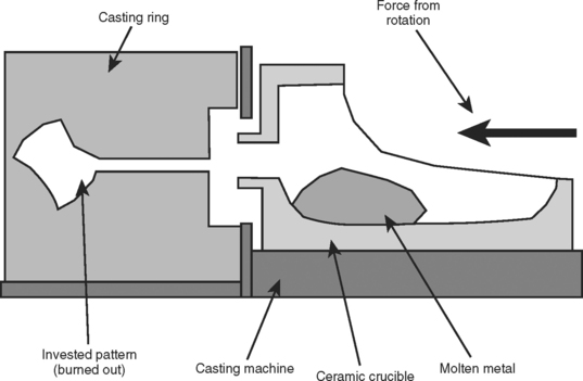
FIGURE 17-13 Diagram showing the relationship between the ceramic crucible used to melt the alloy and the casting ring in a centrifugal casting machine. Both the crucible and the ring are placed on the casting machine. Once molten, the metal is rapidly driven centrifugally out of the crucible and into the mold in the casting ring. The traverse of the molten metal takes less than 1 second. The oxidized elements and flux, which are less dense, lag behind the molten metal as slag.
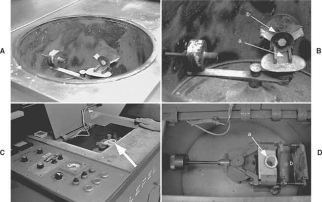
FIGURE 17-14 Pictures of centrifugal casting machines. In A, the centrifugal force is created with a spinning motion powered by a spring and the alloy is heated with a torch. The casting device is in a well to protect the operator from any debris that might fly out during casting. B, A close-up view of the casting machine in A. The crucible (not shown) is placed into the cradle at a, and the casting ring onto the sling at b (see Fig. 17-13). The counterweight of the casting arm is visible at the left, which balances the device as it spins rapidly to centrifugally drive the metal from the crucible into the ring. C, Induction casting machine. In this machine, the metal is melted by an electric current, so no casting torch is necessary. The crucible is visible in the casting well (arrow). D, A close-up view of the casting apparatus in C. The crucible is visible at a, and the ring (not shown) is placed into the space at b. The spinning motion is motor driven, not spring-driven as in A. The counterweight is visible at the left.
With the air pressure type of machine, either compressed room air or some other gas, such as carbon dioxide or nitrogen, can be used to force the molten metal into the mold. The air pressure is applied to the molten metal through a suitable valve mechanism. This type of machine is satisfactory only for making small castings.
Casting machines, both the centrifugal and gas pressure, are available with an attached vacuum system designed to assist the molten metal in filling the mold. In some castings, the added vacuum may be advantageous, but in general, this addition shows little evidence of producing superior quality castings.
Melting the Alloy
To cast a metal restoration, a suitable torch or other heating equipment to melt the alloy is necessary. Various devices are available for each of these operations. The most common method of heating dental alloys for full cast-metal restorations is by using a gas-air torch. A properly adjusted torch develops an adequate temperature for melting dental alloys whose melting ranges are between 870° and 1000° C. Completing the melting operation promptly also depends on the proper adjustment of the torch flame. Poorly adjusted flames can waste time during melting and considerably damage the alloy through excessive oxidation or gas inclusion. Small and irregularly shaped flames should not be used to melt moderate or large quantities of alloy for casting purposes. A well-defined torch flame is the hottest and most effective for such melting operations.
The literature contains many descriptions of the proper flame for heating metals and alloys. One practical method of checking and interpreting the flame condition is to apply the flame to a small piece of copper, approximately the size of a coin, placed on a soldering block. The torch is adjusted as it would be for making a casting and is then directed on the copper. If the copper turns bright and clean as it is heated, the flame and the torch manipulation are correct. If the copper turns to a dark, dull red color, oxidation is occurring and the heating is ineffective. The operator should make the necessary adjustments to eliminate these conditions.
The properly adjusted flame contains well-defined component parts described as inner and outer cones or portions having differing color intensities. For example, the inner, well-defined, light blue central cone is usually accepted as the most effective for heating because it is the least oxidizing portion of the flame. Although an improper flame is the most common cause of oxidation of the base metals in alloys, even a properly adjusted flame causes oxidation if it is held too close to the metal being heated, too far from it, or to one side or another, or if it is moved over the surface or away from the alloy. The dramatic oxidation and ineffective heating that can be seen on the copper are not as evident with noble and high-noble alloys, yet may be observed by the experienced operator who is aware of such conditions.
Modified torches may be used that combine natural gas and oxygen or certain “tank” gases, such as acetylene and oxygen. The natural gas and oxygen combination is mainly used for melting alloys designed for construction of porcelain-metal restorations. The combination of acetylene and oxygen has been used mostly to melt cobalt-chromium and nickel-chromium alloys, which have higher fusion temperatures and are used for removable partial dentures.
Electric melting units of various designs are used in some laboratories to melt the alloys during casting. The advantage of using these units is that slightly less skill is required than is necessary for controlling the torch. However, many of these electric heating units have no limiting controls, and the operator must therefore exercise judgment regarding the proper condition of the alloy to be cast. The electric units are heated either by induction or by resistance heating systems. Those units heated by induction melt alloy much faster than do those heated by torch; if the procedure is not watched closely, the alloy can easily be overheated. An electronic monitor is useful for indicating proper temperature. Melting units with resistance heating take longer to complete the heating and casting operation than do torch-heated units. The slightly longer heating time does not appreciably increase the temperature of the molten alloy, nor does it cause any significant problems.
Regardless of the method of melting the alloy or the type of casting machine used, the following objectives should be kept in mind when casting: (1) the alloy should be heated as quickly as possible to a completely molten condition (above the liquidus temperature); (2) oxidation of the alloy should be prevented by heating the metal with a well-adjusted torch (or other method) and a small amount of flux on the metal surface; and (3) adequate force should be applied to force the well-melted metal into the mold. Finally, after the molten metal is forced into the mold cavity, the casting machine should be allowed to continue to provide pressure on the metal while the metal is solidifying. This pressure encourages complete casting of the margins. Although each of these operations demands care and attention, they are not difficult to master.
SPECIAL CASTING SITUATIONS
Because of the characteristically high melting temperature of the alloys used in ceramic-fused-to-metal restorations, special investments and casting facilities are necessary. Calcium sulfate–bonded investment materials and conventional melting facilities are inadequate for most available alloys because the melting range of the alloys is too high. Generally, phosphate-bonded investments and gas-oxygen torch are used in casting this type of alloy. Phosphate investments are stronger and denser than are gypsum-bonded investments (see Chapter 13). Although the technique for using these special alloys and investments is not complicated or elaborate, the technique recommended by the manufacturers should be followed faithfully to achieve satisfactory surface character and fit of the casting.
Because the phosphate-bonded investment used for ceramic-metal castings is dense, special attention should be given to the manner of spruing of the wax pattern. Proper spruing should facilitate the escape of gases from the mold cavity before the molten metal solidifies completely. The bar type of spruing used for casting these alloys is shown in Fig. 17-4. With this type of spruing, the sprue bar is placed inside the mold as a reservoir to help keep the alloy in the molten stage for a longer time so that a more complete casting can be attained. For single units, the bar is shortened or a ball is used. Note that with a normal spruing method, the pattern is sprued in such a manner as to reduce turbulence in the flow of molten alloy. However, with the bar-spruing method, an attempt is made to increase the turbulence so the investment close to the sprue maintains a higher temperature, which keeps the alloy molten for a longer time. The main disadvantage of the bar type of sprue is the increased amount of alloy required to make castings; for this reason the bar type is not used to make castings of alloys with low melting ranges and gypsum-bonded investments.
If a bar type of sprue is used with a centrifugal casting machine, the casting ring should be placed in the casting machine so the bar sprue is vertical. The leader from the sprue button to the bar should be attached 1 to 2 mm below the top of the bar. In this manner, when the alloy at the tip of the bar sprue freezes, the alloy 1 to 2 mm below the tip remains molten, and feeding from the sprue button to the bar is still possible. The leader from the bar to the wax pattern should be attached to the highest part of the wax pattern. Centrifugal casting machines tend to feed molten alloy straight (as a result of the centrifugal force) and down (from gravity). If the leaders from the sprue button to the bar or from the bar to a one-piece cast bridge are placed in the middle of the bar or bridge, there is a high probability of a miscast. In such a sprue arrangement, the molten alloy must fill the lower portion of the bar and the mold cavity before being forced upward against gravity to fill the upper portion of the bar and the bridge. Proper attachment of the leaders to the bar and to three copings are shown in Fig. 17-4.
Other steps in the investing and casting procedure of ceramic-metal alloys normally include vacuum investing, careful wax elimination, a gas-oxygen torch or other high-temperature melting facility, and centrifugal casting with adequate casting pressure. Special solders may be required with these alloys for certain techniques; with some alloys and solders, the operation requires skilled management only obtained with extensive practical experience.
Casting Co-Cr and Ni-Cr Alloys and Partial-Denture Frameworks
Posterior crowns are often cast in base-metal alloys, but because of their high melting temperatures, phosphate investments are almost always used. Also, as a result of their high freezing temperatures, more shrinkage of the alloy must be compensated for than in gold-based alloys to obtain accurately fitting castings. The extra compensation can be obtained by (1) painting a die spacer (varnish) on the die, but short of the margins, before preparing the wax pattern; or (2) using two layers of ceramic paper liner in the investing ring to make the setting expansion of the investment more effective.
The methods of casting relatively large partial-denture frameworks in base metals differ from the casting of simple restorations such as crowns, although the two operations are similar in principle. In cast partial-denture construction, a suitable cast of refractory material serves as the structure on which the wax pattern is formed. This is done because the wax pattern is too large to be freestanding and must be supported during investing and casting. This refractory cast is prepared by duplicating the master stone model, usually by using the agar duplicating materials described in Chapter 12. Figure 17-15, A, shows a duplicating flask containing the master model before pouring the duplicating material. Fig. 17-15, B, shows the duplicate impression in agar and the separated refractory cast that was prepared in the agar mold.
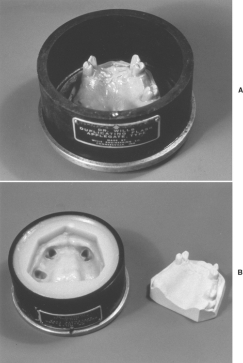
FIGURE 17-15 A duplicating flask used to make a refractory cast onto which a partial denture framework will be waxed and cast. In A, the flask contains the gypsum master cast and is ready to be invested with the agar duplicating material. In B, the agar has set and the original gypsum cast has been removed. The refractory material will then be poured into the mold to create the refractory cast. (Courtesy ER Dootz, Ann Arbor, University of Michigan School of Dentistry.)
Once the refractory cast is prepared, the wax pattern for the partial framework is prepared on the cast and invested, in place, on this cast. Fig. 17-16, A, shows a wax pattern on a refractory cast. Note that the pattern is sprued through the base of the cast. After the wax pattern is formed, the refractory cast with the wax pattern is invested in a casting ring as shown in Fig. 17-16, B, where the sprue button-former has been removed. A gypsum-bonded investment is used when a low-fusing point (<1300° C liquidus) alloy is used, but a phosphate- or silica-bonded investment is used when high-fusing point alloys (>1300° C solidus) are to be cast. The invested pattern is burned out and the investment is heated to the casting temperature, causing thermal expansion. As for any casting, the sum of the setting and thermal expansions compensates for the casting shrinkage of the base metals. A cast restoration is shown in Fig. 17-17.
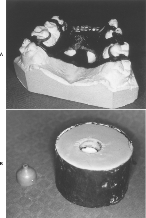
FIGURE 17-16 A, The wax pattern for a partial denture framework has been waxed onto a refractory cast. The sprue for this pattern is through a hole in the base of the cast. B, The wax pattern and refractory cast have been invested and the sprue button-former has been removed. The pattern is now ready for burnout and casting. (Courtesy ER Dootz, Ann Arbor, University of Michigan School of Dentistry.)
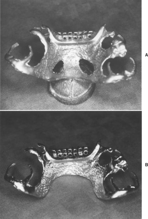
FIGURE 17-17 A, A partial-denture framework has been cast and divested from the investment and refractory cast. The casting button is visible at the bottom of the picture. B, The framework has been polished and the button removed. The framework is now ready to be tried in the mouth. (Courtesy ER Dootz, Ann Arbor, University of Michigan School of Dentistry.)
Because the minor alloying elements of carbon, nitrogen, and oxygen influence the properties of a base metal, it is generally recognized that a pronounced variation in properties can result from the use of variable casting conditions (see Chapter 16). Variables such as mold temperature, temperature of the molten alloy, and the sprue size and arrangement affect the properties of the finished casting as much as does the composition. Therefore, Co-Cr and Ni-Cr alloys are generally considered technique-sensitive. Another reason for this sensitivity is that almost all elements in these alloys, such as chromium, silicon, molybdenum, cobalt, and nickel, react with carbon to form carbides, even though only a relatively small amount of carbon is present in the alloys. Depending on the mold and alloy casting temperature, cooling rate, and other technical variables, carbides of any one of these elements may form, which changes the properties of the alloy. Careful control of manipulative variables in the casting operations is therefore essential.
The alloy melting temperature is an important factor in the selection and control of the melting and casting equipment and in the choice of technique and mold equipment used for the casting of base-metal alloys. Only a base-metal alloy that melts below 1300° C can be cast into a calcium sulfate-bonded investment. It is also possible to cast a low-melting point nickel-chromium alloy against wrought platinum-gold-palladium wire when a flexible partial-denture clasp is required. Because of their higher melting points, other cast base-metal alloys cannot be melted with the conventional blowtorch used for gold-based alloys. It has therefore been necessary to develop special electric or induction melting facilities or, less commonly, to melt the alloy with an oxygen-acetylene torch. Either method is acceptable in the hands of a skillful operator.
Regardless of the method employed to melt the alloy, it is possible to cause severe damage to the properties of a base-metal casting if proper melting practices are not observed. Two sprue buttons from base-metal alloy casting, one sound and free from defects and the other with some porosity and surface irregularities, are shown in Fig. 17-18. More severe damage from excessive overheating and resulting porosities and surface reaction with the mold materials is not uncommon. Castings with poor surface appearance usually also possess inferior physical properties. It is probable that the proper control of the factors related to the casting operation is more important in controlling the properties of the finished structure than are the variations in composition or the choice of different products.
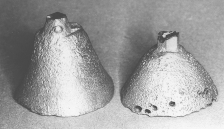
FIGURE 17-18 Sprue buttons from base-metal alloy showing an alloy that was properly heated (left), and one that was slightly overheated (right). Overheating caused the inclusion of several porosities in the alloy.
When casting any of the base metals into molds designed to accommodate the higher melting temperatures of these alloys, certain problems may be encountered that are less common when casting alloys of lower melting temperatures. One problem is that of trapping gases in the mold during the casting process. To have sufficient strength and resistance to thermal shock, some investments for cast base-metal alloys lack sufficient porosity for the rapid escape of gases from the mold cavity when the hot metal enters. Gases may therefore be trapped in the mold cavity and produce voids and casting defects. The effect of such trapped gases on one casting of a cobalt-chromium alloy is clearly shown in Fig. 17-19. The general view of the casting in A shows the location of the defect in a critical area of the appliance. The magnified view of the defective area in B reveals that a large gas bubble became trapped in the molten metal at the time the mold was filled. Before it could be dissipated, the metal solidified. A higher temperature of the casting alloy would have assisted in overcoming this difficulty. Numerous other methods have been proposed to overcome such defects, such as venting to the surface of the mold to permit rapid elimination of gases. Such a method is used in the preparation of cast test bars for specification testing purposes. The skillful spruing and venting of the mold, combined with complete elimination of the wax residue and adequate heating of the metal, tend to reduce this type of defective casting.
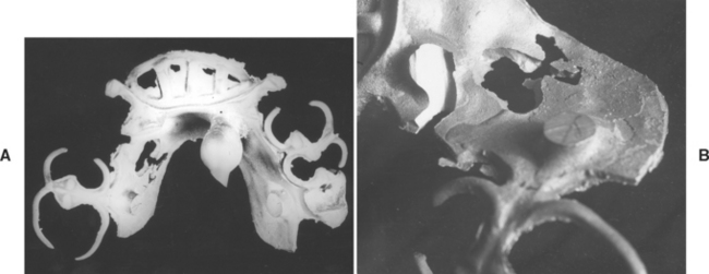
FIGURE 17-19 Pictures of removable partial-denture frameworks with flaws from poor casting techniques. A, The framework has a void in the major connector (left center area). B, A magnified view of the defect in A showing that the defect was caused by metal that was too cold and by gas inclusion in the mold.
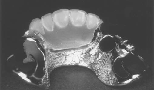
When properly designed and cast, the cast base-metal alloys give acceptable removable partial-denture restorations. A typical appliance of this type, with an acrylic denture base material and artificial teeth attached in the proper relationship is shown in Fig. 17-20. Much clinical study has been given to the choice of clasp material and the proper design of the appliance to give stability and support to the appliance and to the remaining teeth. The mechanics of the design of such restorations are an important aspect of clinical procedures, and rely on the appropriate physical properties of properly cast alloys.
Casting Titanium
Titanium has many desirable properties for use in dentistry, but it is difficult to cast in comparison with the common dental casting alloys because it requires relatively complex and expensive equipment. Two problems in casting titanium are its high melting point and the tendency for the molten metal to become contaminated. The melting point of commercially pure titanium is 1671° C, whereas other dental casting alloys have liquidus temperatures below 1500° C. Titanium readily absorbs several gases when in the molten state. If hydrogen, oxygen, and nitrogen are absorbed, the mechanical properties are adversely affected. To prevent absorption of gases, titanium is cast under the protective atmosphere of argon or in a vacuum. To achieve the high melting temperatures, arc melting in either graphite or water-cooled copper crucibles is used. The casting systems force the metal into the mold using either pressure or centrifugal casting techniques.
The casting design for titanium casting is similar to that of other more common dental alloys. A wax pattern is prepared and sprued, as before, but here only the more temperature resistant investments can be used. Both phosphate-bonded and silica and magnesia investments produce good castings and give casting dimensions that are within the accepted range for base-metal partial-denture and crown castings.
CASTING PROBLEMS
Unless every step in the casting operation is handled properly, the cast restoration may not fit the prepared tooth with the desired accuracy. Naturally, a proper cavity design, an accurate impression of the prepared cavity, a good and accurate die, and proper waxing and investing are all important steps in achieving an acceptable cast restoration. Some common casting problems are described in the following paragraphs and in Fig. 17-21. The complete description of casting problems is beyond the scope of this chapter; detailed information is available in books on casting and metallurgy.
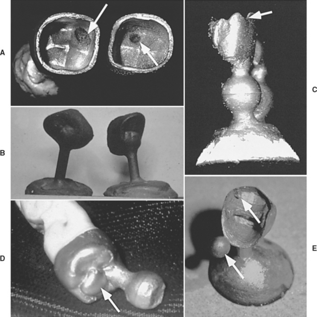
FIGURE 17-21 Pictures of various common casting problems. A, Suckback porosity visible at arrows. B, Dark castings resulting from incomplete burnout of the wax. The black coating is from carbon particles on the alloy and cannot be removed by pickling. C, Incomplete casting of the margins (arrow) and rounded margins. This defect can be caused by inadequate heating of the metal, lack of sufficient porosity in the investment, or inadequate casting pressure (force). D, Positive bubble (arrow) on the external part of the casting was caused by air entrapment during investing. E, Positives on the margins and internal portions of the casting (arrows) caused by air entrapment during investing. Marginal and internal positives are difficult to manage and may require recasting the restoration. (Courtesy Dr. Carl W. Fairhurst, Medical College of Georgia School of Dentistry.)
Improper solidification of metal causes many casting problems. As discussed earlier in this chapter, the shrinkage of wax and alloy is compensated for by various types of expansion of the investment. However, the shrinkage of alloys takes place in two stages as a result of (1) the transformation of the alloy from liquid to solid and (2) the coefficient of expansion of the solid alloy. While the molten alloy is cooling, the temperature eventually reaches the solidification range, causing the alloy to change from a liquid to a solid. This change of state is accompanied by a large shrinkage, which is compensated for only by adhering to a proper casting technique because the expansion of the investment cannot offset such a large shrinkage. The result of not having this expansion is shown in Fig. 17-22. Ideally, molten alloy located farthest from the sprue button should freeze first and molten alloy in the sprue and the sprue button should feed the rest of the pattern, thus compensating for the shrinkage as a result of the change of state.
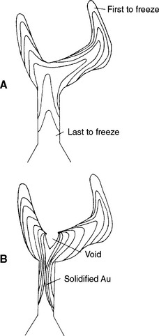
FIGURE 17-22 A, Correct sequence of solidification of an alloy in the investment mold of a full-cast crown. The margins of the casting should freeze first and the button should freeze last. This order allows the molten metal to compensate for the shrinkage realized when each increment of metal goes from the liquid to solid state. B, Incorrect solidification sequence that results in a suckback porosity. The sprue area froze before the cusp area of the crown and the metal in the crown had to feed the shrinking alloy, causing a void in the crown.
As long as the remaining alloy is in the liquid state and the casting machine is rotating, molten alloy will feed the solidified portion of the casting, thereby compensating for the shrinkage. The next layer then solidifies, and this process continues until all the shrinkage resulting from the change of state is compensated for by the available molten alloy in the casting, sprue, and sprue button. If solidification does not occur in this systematic manner and a portion of the alloy in the sprue freezes before the alloy in the casting, what is known as suckback porosity occurs, as shown in Fig. 17-21, A, and Fig. 17-22, B. Expansion of the investment material cannot compensate for this type of porosity.
Improper sprue design can also cause suckback porosity. As seen in Fig. 17-22, molten alloy may enter the mold cavity through a single sprue. Investment at the pulpal floor of a full crown pattern therefore heats up because of the higher temperature of the molten alloy, and it keeps the alloy in this area molten somewhat longer than other areas. Thus if alloy in the sprue solidifies before the alloy in the pulpal floor area, the molten alloy in this area would feed the solidifying alloy in the sprue area. When molten alloy in the pulpal floor area solidifies and shrinks because of the change of state, it cannot be fed. As a result, a large suckback porosity under the sprue occurs. Because the cause of the suckback porosity is the improper sequence in the solidification of the alloy, the precautions in the following paragraphs may help to prevent it.
A Y-shaped sprue can be used instead of a single sprue. In this instance, only half of the molten alloy enters the mold cavity through each leg of the Y-sprue, so the temperature of the investment under the sprue does not rise as high. However, the arms of the Y must be widely separated to prevent the investment between the arms from overheating, which could also cause suckback porosity. If a Y-sprue has already been employed, the diameter of each leg of the Y can be increased or an extra 1 to 2 g of gold alloy can be used, which will keep the alloy in the sprue and the sprue button in the molten state somewhat longer and will better feed the solidifying alloy.
Another possible solution to prevent suckback is to increase the mold temperature from 500° C, which is used with many investments and techniques, to 650° or 700° C. With a higher mold temperature, the difference in temperature between the investment located around the sprue and the investment in the area of the pulpal floor of the full crown is decreased. This decrease helps the molten alloy at the pulpal floor to solidify before the alloy at the sprue. Studies have shown that when a gold alloy with a solidification temperature of 940° C was heated to 1040° C and cast into a mold with a temperature of 500° C, the temperature of the investment 1 mm away from the sprue reached only 585° C, whereas the temperature of the investment 1 mm away from the area of the pulpal floor was as high as 900° C. Thus, the difference between the solidification temperature of the alloy and the temperature of the investment at the pulpal floor was only 40° C, whereas the difference near the sprue was 355° C. Therefore, the molten alloy decreased in temperature faster around the sprue than at the pulpal floor, and the sprue solidified sooner. When the temperature of the mold was increased from 500° to 700° C, the temperature of the investment 1 mm away from the pulpal floor increased from 900° C to 906° to 910° C, whereas the temperature of the investment around the sprue area increased from 585° to 800° C. Thus, the difference between the solidification temperature of the alloy and the temperature of the investment in the area of the pulpal floor was 30° to 35° C, whereas around the sprue it was 140° C. In other words, by increasing the mold temperature before casting, the variation of the mold temperature in different areas after casting is reduced.
Increasing the temperature of the molten alloy or using an extra turn on a centrifugal casting machine in an attempt to drive the alloy more completely into the mold does not help eliminate suckback porosity. In fact, this strategy may increase suckback porosity by increasing the temperature of the investment in local areas as the alloy is driven across the investment at a higher rate. The higher forces of alloy entry also increase the chances of cracking the investment, either from thermal shock or from mechanical failure. Miscasts can be caused by a host of other factors, including incomplete wax elimination, overheating of alloys, insufficient casting pressure, insufficient escape of mold gases, and incorrect spruing. These topics have been discussed in other parts of this chapter.
Other Casting Problems
With calcium sulfate–bonded investments, when the color of a casting is black after removal from the investment, the cause is probably one of the following: (1) the wax was not completely eliminated, (2) the mold remained in the oven too long, (3) the oxidizing flame was used in melting the alloy, or (4) the investment did not contain any deoxidizing agents. As mentioned earlier, when wax is not completely eliminated, very fine particles of carbon cover the investment pores through which the gas in the mold cavity is supposed to escape. Depending on the amount of carbon remaining on the walls of the mold cavity when the molten metal enters, the casting may be complete but black in color (see Fig. 17-21, B), or it may be incomplete (see Fig. 17-21, C). The black color in this instance cannot be cleaned by routine pickling action, which is described later in this chapter, because most pickling solutions are acidic and most acids are not effective in removing carbon from the surface of noble and high-noble alloys.
However, if the black color of the gold casting is removed by the normal pickling procedure, it was caused mainly by copper oxides formed during casting. Most casting investments contain some reducing agents to provide a reducing atmosphere when the molten alloys are entering the mold cavity. If the investment mold is left too long in an oven, all the deoxidizers will be decomposed and eliminated. Thus, when the molten alloy enters the mold cavity, the oxidation of the copper is not prevented, and the casting will be black. Some investments routinely produce blackened castings because the manufacturers do not add any deoxidizing agents. Also, if an oxidizing flame is used in melting the alloy, the casting will be black. Castings that are black because of oxidation of some of the elements in the alloy can easily be cleaned, and the original alloy color can be restored by normal pickling procedures.
Insufficient casting pressure or underheating of alloys usually results in castings with rounded margins (see Fig. 17-21, C). The rounded margins are caused by freezing of the alloy before the gases are forced from the mold cavity. As mentioned previously, the slow escape of mold gases can be caused by the investment being too thick over the end of the ring or by a phosphate-bonded investment that has a glassy surface coating that has not been removed. However, rounded margins can also be caused when the alloy cannot exert enough force while entering the mold cavity. This situation can be caused by an underheated alloy that is too viscous or does not stay in the liquid state long enough to force the gases out and reach the marginal areas of the mold. Alternatively, the rounded margins can be caused when the casting machine is underwound and the force on the molten alloy is insufficient to drive the alloy into the mold before the alloy freezes.
Finally, investment errors can result in miscasts that are apparent only after the casting process is complete. Perhaps the most common problem is the trapping of air in the investment during the investing process (see Fig. 17-21, D, E). These air bubbles may occur on the outside or inside of the casting. If they occur on the outside (see Fig. 17-21, D), they are theoretically removable, but often at great expense of time and money (lost metal). However, the fit of the casting is not affected. If the voids occur on the margins or the inside of the casting (see Fig. 17-21, E), successful removal is extremely difficult and often the restoration will have to be recast.
CLEANING AND PICKLING ALLOYS
The surface oxidation or other contamination of dental alloys is a troublesome occurrence. The oxidation of base metals in most alloys can be kept to a minimum or avoided by using a properly adjusted method of heating the alloy and a suitable amount of flux when melting the alloy (see discussion on fluxes later in this chapter). Despite these precautions, as the hot metal enters the mold, certain alloys tend to become contaminated on the surface by combining with the hot mold gases, reacting with investment ingredients, or physically including mold particles in the metal surface. The surface of most cast, soldered, or otherwise heated metal dental appliances is cleaned by warming the structure in suitable solutions, mechanical polishing, or other treatment of the alloy to restore the normal surface condition.
Surface tarnish or oxidation can be removed by the process of pickling. Castings of noble or high-noble metal may be cleaned in this manner by warming them in a 50% sulfuric acid and water solution (Fig. 17-23). Today, most commercially available pickling solutions are not made of the ordinary inorganic acid solutions and do not release poisonous gases on boiling (as sulfuric acid does). In either case, the casting to be cleaned is placed in a suitable porcelain beaker with the pickling solution and warmed gently, but short of the boiling point. After a few moments of heating, the alloy surface normally becomes bright as the oxides are reduced. When the heating is completed, the acid may be poured from the beaker into the original storage container and the casting is thoroughly rinsed with water. Periodically, the pickling solution should be replaced with fresh solution to avoid excessive contamination.
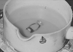
FIGURE 17-23 Pickling an alloy. After casting, the alloy (with sprue attached) is placed into the warmed pickling solution for a few seconds. The pickling solution will reduce oxides that have formed during casting. However, pickling will not eliminate a dark color caused by carbon deposition (see Fig. 17-21, B). The effect of the solution can be seen by comparing the submerged surfaces to those that have still not contacted the solution. (Courtesy Dr. Carl W. Fairhurst, Medical College of Georgia School of Dentistry.)
There are several important notes about pickling. With the diversity of compositions of casting alloys available today, it is prudent to follow the manufacturer’s instructions for pickling precisely, as all pickling solutions may not be compatible with all alloys. Furthermore, the practice of dropping a red-hot casting into the pickling solution should be avoided. This practice may alter the phase structure of the alloy or warp thin castings, and splashing acid may be dangerous to the operator. Finally, steel or stainless steel tweezers should not be used to remove castings from the pickling solutions. The pickling solution may dissolve the tweezers and plate the component metals onto the casting. Rubber-coated or Teflon tweezers are recommended for this purpose.
SOLDERING TECHNIQUES
GENERAL SUGGESTIONS FOR SOLDERING
The details for dental soldering are adequately described in textbooks related to other fields of dentistry. Certain principles of the freehand and investment techniques are emphasized here. For successful soldering, both the technique and the selection of solder are important. Many of the materials and techniques used in casting are also useful in soldering.
Dental solders are supplied in a variety of shapes, such as strips, rods, wires, or cubes, each of which is convenient for certain operations. Thin strips are the conventional form for general applications, and small cubes, approximately 1-mm square, are convenient for soldering a contact area on an inlay or crown. Rods are often notched along two sides, which permits them to hold flux better than a smooth form. Also, when melted, the notched forms do not roll back into a ball as easily as smooth forms. Choosing a particular shape depends on the operation to be performed; each shape is available in a range of fineness.
Proper application of fluxes provides a protective coating that prevents oxidation of the solder and parts being soldered. The flux dissolves surface oxides and allows the melted solder to wet and flow onto the adjoining alloy surfaces. The fluxes used for soldering gold alloys are combinations of borax and boric acid, with potassium fluoride added to some. Too much flux is as undesirable as not enough flux. See the discussion on fluxes at the end of this chapter.
The careful and skillful use of the soldering torch flame is important to a high-quality soldered joint. A well-defined, not-too-large, pointed flame is advisable for the final heating of solder in a localized area, but a larger, less well defined flame of the “brush” type may be used for the initial heating. The flame should not be applied directly to the parts to be joined until the flux has melted and formed a uniform layer over the surface. Applying a hot flame to the flux too quickly causes the flux to form droplets rather than a film. Once the flame has been applied to the spot to be soldered, it should not be withdrawn until soldering is completed. A protective envelope should be created around the spot to be soldered with the reducing portion of the flame. The operation should be completed in the shortest time possible to avoid oxidation of the base metal ingredients of the alloys involved and to prevent damage to the microstructures of the alloys.
Overheating during the soldering operation will cause (1) pits in the solder, (2) penetration or burning through thin sections, and (3) a loss of strength because of diffusion of the solder into the other metals or loss of fibrous microstructure. Underheating will cause pitting from the retention of unmelted flux and failure of the solder to flow and adhere to all surfaces. Good wetting of the surfaces by the solder is imperative for satisfactory joining of the parts. Solder that is not well heated tends to “ball” and fails to spread properly. Both overheating and underheating will result in a weaker solder joint. For this reason, the proper and careful heating and fluxing of the solder are essential.
Sometimes the flow of the solder should be restricted from parts of the restoration, such as the margins or the occlusal grooves. Flow into these areas can be prevented with an antiflux material, which should be applied to the surface before the flux or solder is applied. Solder does not flow into an area contaminated with graphite; a soft lead pencil is therefore an effective antiflux. Other materials, such as rouge (iron oxide) or whiting (calcium carbonate) in an alcohol and water suspension, are effective antifluxes for prolonged heating or high-temperature heating, which can burn off the graphite.
The distance between the parts to be joined can influence the accuracy of the final appliance. If the parts are in intimate contact, they tend to expand and push apart on heating, whereas if the distance is too great, the parts tend to draw together as the solder solidifies. A clearance of a few hundredths of a millimeter (0.13 mm) between the parts to be joined is optimal when using the investment-soldering technique. This thickness can be practically estimated by the thickness of a typical business card. When attempting free hand soldering of wires for orthodontic or other appliances, a closer adaptation of the parts is possible. The shape of the joint and the purpose of the appliance will ultimately determine the appropriate distance between the soldered parts.
Despite certain well-established principles, soldering is an art. The timing and type of heating, selection of the type and shape of the solder, contour of parts to be joined, and application of flux cannot always be dictated by specific rules. Ultimately, the experience of the operator plays a significant role in any successful soldering operation.
INFRARED SOLDERING
Instead of using a torch to provide heat, an infrared heating unit is available specifically for dental soldering. The unit uses the light from a 1000-watt, tungsten-filament, quartz-iodine bulb, which is mounted at the primary focal point of a gold-plated, elliptical reflector. The material to be soldered is placed at the reflector’s secondary focal point, at which the reflected infrared energy of the tungsten light source is focused. This equipment, shown in Fig. 17-24, can be used for the high-temperature soldering of alloys for porcelain-fused-to-metal bridges at 1150° C. The main problem in the use of this unit is locating the focal center of the light on the spot to be soldered. The infrared energy must be focused on the crowns and not on the solder itself. Failure to focus on the right spot on the crown can result in cold joints that are porous.
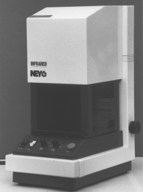
CASTING AND SOLDERING FLUXES
A flux is a substance applied to the surface of molten metal primarily to prevent oxygen from contacting the hot metal and thereby causing oxidation. In addition, flux dissolves oxides that may form while the metal is heated; the resulting solution of oxides or other extraneous matter in the flux constitutes a slag. A flux also facilitates the free flow of solder; it helps solder to wet and spread over the metal surface. For a flux to be effective, it must have a fusion temperature below that of the alloy being heated, but should not burn or volatilize readily.
NOBLE AND HIGH-NOBLE ALLOYS
Borax, or sodium tetraborate ((Na2B4)7 · 10H2O), can dissolve the metal oxides (mainly copper oxides) that occur on noble and high-noble alloys, and therefore is commonly used as a flux in dentistry. Dehydrated sodium tetraborate is known as borax glass and can be used in the dry powder form. When melted, borax glass is a clear, viscous liquid that does not volatilize readily when heated. It can be made more fluid by adding boric acid or other salts, which aid in spreading of the flux on the hot metal surface. Boric acid is not used alone for fluxing purposes, as is sometimes done with borax. Dehydrated borax glass is preferred to the ordinary hydrated borax, which liberates water vapor on being heated and, as a result, effervesces and bubbles up over the surface of the hot meal without forming an effective surface covering.
Fluxes are available in a variety of forms, which are usually designated for specific applications in soldering or casting operations. Liquid flux is principally a solution of borax and boric acid in water, and is applied in soldering operations of orthodontic appliances and bridge structures in which a minimum of flux is desired. A saturated solution, or lower concentration, of the ingredients may be used, and smaller quantities of other salts, such as potassium carbonate or ammonium chloride, may be added to some liquid fluxes. Also available are paste fluxes formed from mixtures of about one-third borax added to a mineral grease, such as petroleum jelly, with other chemicals added as desired. Pastes are convenient for soldering operations in which a large quantity of flux is desired and its application is directed to a specific area. Powder fluxes, which are normally used for metals during the melting for a casting operation, are sprinkled lightly on the metal. Powder fluxes may contain finely divided charcoal or other ingredients mixed with borax and boric acid; this combination gives added protection by producing what is described as a reducing flux. The charcoal not only helps prevent the formation of oxides on the metal surface, but also reduces oxides that have already formed to free metal. Fluxes in the powder form also may contain a very small percentage (1% to 2%) of finely divided silica flour, which holds the molten flux in position on the surface of the hot metal.
CHROMIUM-CONTAINING ALLOYS
When soldering stainless-steel or cast cobalt-based alloys that contain chromium, a special flux is required because borax and boric acid alone do not dissolve chromium oxides. Normally the fluxes for these soldering operations should contain about 50% to 60% potassium fluoride, or another fluoride, mixed with 25% to 35% boric acid (H3BO4), 6% to 8% borax glass, and 8% to 10% potassium or sodium carbonate. An equal mixture of boric acid and the fluoride salt may be formed into a paste for soldering when they are ground together with a few drops of water, which is considered effective in such soldering operations. Other similar compositions have been recommended. Pastes should not be formulated with petroleum grease for these applications because the carbon formed in heating alters the properties of the alloy being soldered or cast.
Choosing the proper flux (borax or fluoride) for the soldering operation is important. The choice of flux is dictated by the type of alloy to be soldered or cast, not by the type of solder used. If the alloy contains chromium, such as stainless steel wires for orthodontics or cobalt-chromium alloys for partial dentures, the proper choice is fluoride flux, regardless of whether gold- or silver-based solder is used. If noble or high-noble alloys are to be soldered, the proper choice is borax flux, regardless of the solder employed.
A principle governing the use of fluxes for any purpose is that neither too much nor too little should be applied to the metal during the heating operation. When too little flux is applied, it tends to burn off and be ineffective; when too much flux is applied, it may become entangled in the molten metal to produce a defect by inclusion.
Anusavice KJ, ed. Phillips’ science of dental materials, ed 11, St Louis: Saunders, 2003.
Asgar, K, Casting restorations. Clark, JW, eds. Clinical dentistry, 4. New York: Harper & Row, 1976.
Craig, RG, Powers, JM, Wataha, JC. Dental materials: properties and manipulation, ed 8. St. Louis: Mosby, 2004.
Dootz, ER. Technology of casting and soldering alloys for metal-ceramic applications. Ceramic Eng Sci Proc. 1985;6:84.
Mackert, JR. An expert system for analysis of casting failures. Int J Prosthodont. 1988;1:268.
O’Brien WJ, ed. Dental materials and their selection, ed 2, Carol Stream, IL: Quintessence, 1997.
Tuccillo, JJ, Nielsen, JP. Sprue design for cast gold alloys. Dent Lab Rev. 1964;39:14. (June), 14 (July)
Wagner, AW. Causes and cures for porosities in dental casting. Quint Dent Technol. 1979;3:57.