Chapter 5 Dental X-ray generating equipment
This chapter summarizes the more important practical aspects of dental X-ray generating equipment. There are several different units available from various manufacturers. They vary in appearance, complexity and cost, but all consist of three main components:
Three modern dental units, suitable for both film and digital imaging are shown in Figure 5.1. Their control panels are shown in Figure 5.6. Dental units can be either fixed (wall-mounted or ceiling-mounted) or mobile (attached to a sturdy frame on wheels).
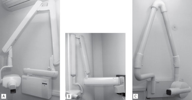
Fig. 5.1 Examples of modern dental X-ray generating equipment showing the tubeheads and positioning arms. A Prostyle Intra® manufactured by Planmeca. B Focus® manufactured by Instrumentarium Imaging. C Heliodent® DS manufactured by Sirona.
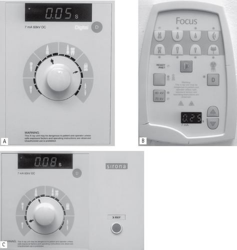
Fig. 5.6 Examples of modern dental X-ray equipment control panels. A Prostyle Intra® manufactured by Planmeca. B Focus® manufactured by Instrumentarium Imaging. C Heliodent® DS manufactured by Sirona. They are all anatomical timers suitable for film and digital (D) imaging.
Ideal requirements
Main components of the tubehead
A diagram of a typical tubehead is shown in Figure 5.2. The main components include:
• The glass X-ray tube, including the filament, copper block and the target (see Ch. 2)
• The step-up transformer required to step-up the mains voltage of 240 volts to the high voltage (kV) required across the X-ray tube
• The step-down transformer required to step-down the mains voltage of 240 volts to the low voltage current required to heat the filament
• A surrounding lead shield to minimize leakage
• Surrounding oil to facilitate heat removal
• Aluminium filtration to remove harmful low-energy (soft) X-rays (see Fig. 5.3)
• The collimator — a metal disc or cylinder with central aperture designed to shape and limit the beam size to a rectangle (the same size as intraoral film) or round with a maximum diameter of 6 cm (see Figs 5.3 and 5.4)
• The spacer cone or beam-indicating device (BID) — a device for indicating the direction of the beam and setting the ideal distance from the focal spot on the target to the skin. The required focus to skin (fsd) distances are:
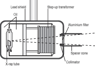
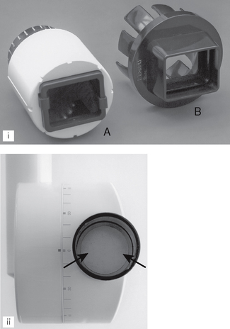
Fig. 5.3 (i) Examples of adaptors/collimators designed to change the shape of the beam from circular to rectangular. A Sirona Heliodent® DS collimator, B Dentsply’s Universal collimator. (ii) Aluminium filter (arrowed) viewed from down the spacer cone on the Sirona Heliodent® DS.
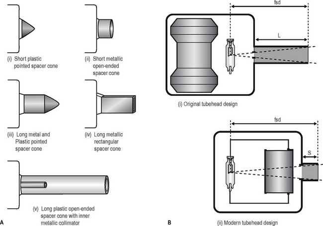
Fig. 5.4A Diagrams showing various designs and shapes of spacer cones or beam-indicating devices. Note: The short plastic pointed spacer cone is NOT recommended. B Diagrams showing (i) the original tubehead design with the X-ray tube at the front of the head, thus requiring a long spacer cone (L) to achieve a near-parallel X-ray beam and the correct focus to skin distance (fsd) and (ii) the modern tubehead design with the X-ray tube at the back of the head, thus requiring only a short spacer cone(S) to achieve the same focus to skin distance (fsd).
It is the length of the focal spot to skin distance (fsd), that is important NOT the physical length of the spacer cone. Various designs are illustrated in Figure 5.4.
Focal spot size and the principle of line focus
As stated in Chapter 1, the focal spot (the source of the X-rays) should be ideally a point source to reduce blurring of the image — the penumbra effect — as shown in Figure 5.5A. However, the heat produced at the target by the bombarding electrons needs to be distributed over as large an area as possible. These two opposite requirements are satisfied by using an angled target and the principle of line focus, as shown in Figure 5.5B.
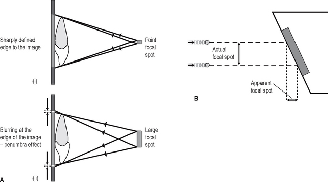
Fig. 5.5A Diagrams showing the effect of X-ray beam source (focal spot) size on image blurring (i) a small or point source, (ii) a large source. B The principle of line focus, diagram of the target and focal spot showing how the angled target face allows a large actual focal spot but a small apparent focal spot.
Main components of the control panel
Examples of three typical control panels are shown in Figure 5.6. The main components include:
Circuitry and tube voltage
The mains supply to the X-ray machine of 240 volts has two functions:
• To generate the high potential difference (kV) to accelerate the electrons across the X-ray tube via the step-up transformer
• To provide the low-voltage current to heat the tube filament via the step-down transformer.
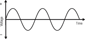
However, the incoming 240 volts is an alternating current with the typical waveform shown in Figure 5.7. Half the cycle is positive and the other half is negative. For X-ray production, only the positive half of the cycle can be used to ensure that the electrons from the filament are always drawn towards the target. Thus, the stepped-up high voltage applied across the X-ray tube needs to be rectified to eliminate the negative half of the cycle. Four types of rectified circuits are used:
The waveforms resulting from these rectified circuits, together with graphic representation of their subsequent X-ray production, are shown in Figure 5.8. These changing waveforms mean that equipment is only working at its optimum or peak output at the top of each cycle. The kilovoltage is therefore often described as the kVpeak or kVp. Thus a 50 kVp half-wave rectified X-ray set only in fact functions at 50 kV for a tiny fraction of the total time of any exposure.
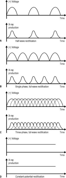
Fig. 5.8 Diagrams showing the waveforms and X-ray production graphs resulting from different forms of rectification.
Modern designs favour constant potential circuitry, often referred to as DC units, which keep the kilovoltage at kVpeak throughout any exposure, thus ensuring that:
Other X-ray generating apparatus
The other common X-ray generating equipment encountered in dentistry includes:
• Panoramic X-ray machines often combined with cephalometric skull equipment (see Ch. 17)
• Skull units, such as the Craniotome® or Orbix® (see Ch. 14)
The main features and practical components of these machines are outlined in later chapters.