Chapter 2 The production, properties and interactions of X-rays
INTRODUCTION
X-rays and their ability to penetrate human tissues were discovered by Röentgen in 1895. He called them X-rays because their nature was then unknown. They are in fact a form of high-energy electromagnetic radiation and are part of the electromagnetic spectrum, which also includes low-energy radiowaves, television and visible light (see Table 2.1).
Table 2.1 The electromagnetic spectrum ranging from the low energy (long wavelength) radio waves to the high energy (short wavelength) X- and gamma-rays
| Radiation | Wavelength | Photon energy |
|---|---|---|
| Radio, television and radar waves | 3 × 10⁴ m to 100 μm | 4.1 × 10⁻¹¹ eV to 1.2 × 10⁻² eV |
| Infra-red | 100 μ m to 700 nm | 1.2 × 10⁻² eV to 1.8 eV |
| Visible light | 700 nm to 400 nm | 1.8 eV to 3.1 eV |
| Ultra-violet | 400 nm to 10 nm | 3.1 eV to 124 eV |
| X-and gamma-rays | 10 nm to 0.01 pm | 124 eV to 124 MeV |
X-rays are described as consisting of wave packets of energy. Each packet is called a photon and is equivalent to one quantum of energy. The X-ray beam, as used in diagnostic radiology, is made up of millions of individual photons.
To understand the production and interactions of X-rays a basic knowledge of atomic physics is essential. The next section aims to provide a simple summary of this required background information.
ATOMIC STRUCTURE
Atoms are the basic building blocks of matter. They consist of minute particles — the so-called fundamental or elementary particles — held together by electric and nuclear forces. They consist of a central dense nucleus made up of nuclear particles — protons and neutrons — surrounded by electrons in specific orbits or shells (see Fig. 2.1).
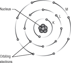
Fig. 2.1 Diagrammatic representation of atomic structure showing the central nucleus and orbiting electrons.
Useful definitions
• Atomic number (Z) — The number of protons in the nucleus of an atom
• Neutron number (N) — The number of neutrons in the nucleus of an atom
• Atomic mass number (A) — Sum of the number of protons and number of neutrons in an atom (A = Z + N)
• Isotopes — Atoms with the same atomic number (Z) but with different atomic mass numbers (A) and hence different numbers of neutrons (N)
• Radioisotopes — Isotopes with unstable nuclei which undergo radioactive disintegration (see Ch. 17).
Main features of the atomic particles
Nuclear particles (nucleons)
Electrons
• Mass = 1/1840 of the mass of a proton
• Charge = negative: –1.6 × 10⁻¹⁹ coulombs
• Electrons move in predetermined circular or elliptical shells or orbits around the nucleus
• The shells represent different energy levels and are labelled K,L,M,N,O outwards from the nucleus
• The shells can contain up to a maximum number of electrons per shell:
• Electrons can move from shell to shell but cannot exist between shells — an area known as the forbidden zone
• To remove an electron from the atom, additional energy is required to overcome the binding energy of attraction which keeps the electrons in their shells.
Summary of important points on atomic structure
• In the neutral atom, the number of orbiting electrons is equal to the number of protons in the nucleus. Since the number of electrons determines the chemical behaviour of an atom, the atomic number (Z) also determines this chemical behaviour. Each element has different chemical properties and thus each element has a different atomic number. These form the basis of the periodic table.
• Atoms in the ground state are electrically neutral because the number of positive charges (protons) is balanced by the number of negative charges (electrons).
• If an electron is removed, the atom is no longer neutral, but becomes positively charged and is referred to as a positive ion. The process of removing an electron from an atom is called ionization.
• If an electron is displaced from an inner shell to an outer shell (i.e. to a higher energy level), the atom remains neutral but is in an excited state. This process is called excitation.
• The unit of energy in the atomic system is the electron volt (eV), 1eV = 1.6 × 10⁻¹⁹ joules.
X-RAY PRODUCTION
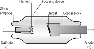
X-rays are produced when energetic (high-speed) electrons bombard a target material and are brought suddenly to rest. This happens inside a small evacuated glass envelope called the X-ray tube (see Fig. 2.2).
Main features and requirements of an X-ray tube
• The cathode (negative) consists of a heated filament of tungsten that provides the source of electrons.
• The anode (positive) consists of a target (a small piece of tungsten) set into the angled face of a large copper block to allow efficient removal of heat.
• A focusing device aims the stream of electrons at the focal spot on the target.
• A high-voltage (kilovoltage, kV) connected between the cathode and anode accelerates the electrons from the negative filament to the positive target. This is sometimes referred to as kVp or kilovoltage peak, as explained later in Chapter 5.
• A current (milliamperage, mA) flows from the cathode to the anode. This is a measure of the quantity of electrons being accelerated.
• A surrounding lead casing absorbs unwanted X-rays as a radiation protection measure since X-rays are emitted in all directions.
Practical considerations
The production of X-rays can be summarized as the following sequence of events:
1. The filament is electrically heated and a cloud of electrons is produced around the filament.
2. The high-voltage (potential difference) across the tube accelerates the electrons at very high speed towards the anode.
3. The focusing device aims the electron stream at the focal spot on the target.
4. The electrons bombard the target and are brought suddenly to rest.
5. The energy lost by the electrons is transferred into either heat (about 99%) or X-rays (about 1%).
6. The heat produced is removed and dissipated by the copper block and the surrounding oil.
7. The X-rays are emitted in all directions from the target. Those emitted through the small window in the lead casing constitute the beam used for diagnostic purposes.
Interactions at the atomic level
The high-speed electrons bombarding the target (Fig. 2.3) are involved in two main types of collision with the tungsten atoms:
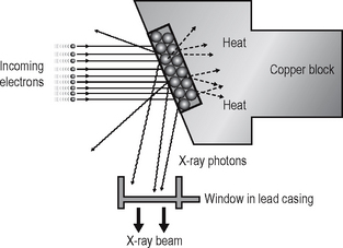
Fig. 2.3 Diagram of the anode enlarged, showing the target and summarizing the interactions at the target.
Heat-producing collisions
• The incoming electron is deflected by the cloud of outer-shell tungsten electrons, with a small loss of energy, in the form of heat (Fig. 2.4A).
• The incoming electron collides with an outer shell tungsten electron displacing it to an even more peripheral shell (excitation) or displacing it from the atom (ionization), again with a small loss of energy in the form of heat (Fig. 2.4B).
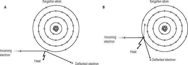
Fig. 2.4A Heat-producing collision: the incoming electron is deflected by the tungsten electron cloud. B Heat-producing collision: the incoming electron collides with and displaces an outer-shell tungsten electron.
Important points to note
• Heat-producing interactions are the most common because there are millions of incoming electrons and many outer-shell tungsten electrons with which to interact.
• Each individual bombarding electron can undergo many heat-producing collisions resulting in a considerable amount of heat at the target.
• Heat needs to be removed quickly and efficiently to prevent damage to the target. This is achieved by setting the tungsten target in the copper block, utilizing the high thermal capacity and good conduction properties of copper.
X-ray-producing collisions
• The incoming electron penetrates the outer electron shells and passes close to the nucleus of the tungsten atom. The incoming electron is dramatically slowed down and deflected by the nucleus with a large loss of energy which is emitted in the form of X-rays (Fig. 2.5A).
• The incoming electron collides with an inner-shell tungsten electron displacing it to an outer shell (excitation) or displacing it from the atom (ionization), with a large loss of energy and subsequent emission of X-rays (Fig. 2.5B).
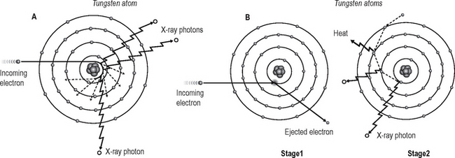
Fig. 2.5A X-ray-producing collision: the incoming electron passes close to the tungsten nucleus and is rapidly slowed down and deflected with the emission of X-ray photons. B X-ray-producing collision: Stage 1 — the incoming electron collides with an inner-shell tungsten electron and displaces it; Stage 2 — outer-shell electrons drop into the inner shells with subsequent emission of X-ray photons.
X-ray spectra
The two X-ray-producing collisions result in the production of two different types of X-ray spectra:
Continuous spectrum
The X-ray photons emitted by the rapid deceleration of the bombarding electrons passing close to the nucleus of the tungsten atom are sometimes referred to as bremsstrahlung or braking radiation. The amount of deceleration and degree of deflection determine the amount of energy lost by the bombarding electron and hence the energy of the resultant emitted photon. A wide range or spectrum of photon energies is therefore possible and is termed the continuous spectrum (see Fig. 2.6).
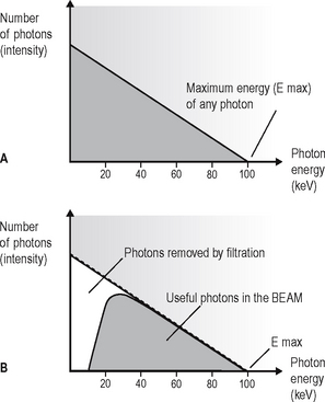
Fig. 2.6A Graph showing the continuous X-ray spectrum at the target for an X-ray tube operating at 100 kV. B Graph showing the continuous spectrum in the emitted beam, as the result of filtration.
Summary of important points
• Small deflections of the bombarding electrons are the most common, producing many low-energy photons.
• Low-energy photons have little penetrating power and most will not exit from the X-ray tube itself. They will not contribute to the useful X-ray beam (see Fig. 2.6B). This removal of low-energy photons from the beam is known as filtration (see later).
• Large deflections are less likely to happen so there are relatively few high-energy photons.
• The maximum photon energy possible (E max) is directly related to the size of the potential difference (kV) across the X-ray tube.
Characteristic spectrum
Following the ionization or excitation of the tungsten atoms by the bombarding electrons, the orbiting tungsten electrons rearrange themselves to return the atom to the neutral or ground state. This involves electron ‘jumps’ from one energy level (shell) to another, and results in the emission of X-ray photons with specific energies. As stated previously, the energy levels or shells are specific for any particular atom. The X-ray photons emitted from the target are therefore described as characteristic of tungsten atoms and form the characteristic or line spectrum (see Fig. 2.7). The photon lines are named K and L, depending on the shell from which they have been emitted.
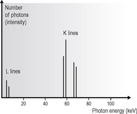
Fig. 2.7 Graph showing the characteristic or line spectrum at the target for an X-ray tube (with a tungsten target) operating at 100kV.
Summary of important points
• Only the K lines are of diagnostic importance since the L lines have too little energy.
• The bombarding high-speed electron must have sufficient energy (69.5kV) to displace a K-shell tungsten electron to produce the characteristic K line on the spectrum. (The energy of the bombarding electrons is directly related to the potential difference (kV) across the X-ray tube, see later.)
• Characteristic K-line photons are not produced by X-ray tubes with tungsten targets operating at less than 69.5 kV — referred to as the critical voltage (Vc).
• Dental X-ray equipment operates usually between 50 kV and 90 kV (see later).
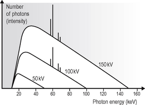
Combined spectra
In X-ray equipment operating above 69.5kV, the final total spectrum of the useful X-ray beam will be the addition of the continuous and characteristic spectra (see Fig. 2.8).
Summary of the main properties and characteristics of X-rays
• X-rays are wave packets of energy of electromagnetic radiation that originate at the atomic level.
• Each wave packet is equivalent to a quantum of energy and is called a photon.
• An X-ray beam is made up of millions of photons of different energies.
• The diagnostic X-ray beam can vary in its intensity and in its quality:
• The factors that can affect the intensity and/or the quality of the beam include:
• In free space, X-rays travel in straight lines.
• Velocity in free space = 3 × 10⁸ m s–1
• In free space, X-rays obey the inverse square law:
Doubling the distance from an X-ray source reduces the intensity to ¼ (a very important principle in radiation protection, see Ch. 8).
• No medium is required for propagation.
• Shorter-wavelength X-rays possess greater energy and can therefore penetrate a greater distance.
• Longer-wavelength X-rays, sometimes referred to as soft X-rays, possess less energy and have little penetrating power.
• The energy carried by X-rays can be attenuated by matter, i.e. absorbed or scattered (see later).
• X-rays are capable of producing ionization (and subsequent biological damage in living tissue, see Ch. 4) and are thus referred to as ionizing radiation.
• X-rays are undetectable by human senses.
• X-rays can affect film emulsion to produce a visual image (the radiograph) and can cause certain salts to fluoresce and to emit light — the principle behind the use of intensifying screens in extraoral cassettes and digital sensors (see Ch. 6).
INTERACTION OF X-RAYS WITH MATTER
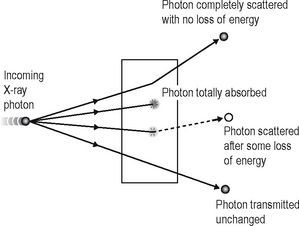
When X-rays strike matter, such as a patient’s tissues, the photons have four possible fates, shown diagrammatically in Figure 2.9. The photons may be:
• Completely scattered with no loss of energy
• Absorbed with total loss of energy
Definition of terms used in X-ray interactions
• Scattering — change in direction of a photon with or without a loss of energy
• Absorption — deposition of energy, i.e. removal of energy from the beam
• Attenuation — reduction in the intensity of the main X-ray beam caused by absorption and scattering
Attenuation = Absorption + Scattering
• Ionization — removal of an electron from a neutral atom producing a negative ion (the electron) and a positive ion (the remaining atom).
Interaction of X-rays at the atomic level
There are four main interactions at the atomic level, depending on the energy of the incoming photon, these include:
• Unmodified or Rayleigh scattering — pure scatter
• Photoelectric effect — pure absorption
Only two interactions are important in the X-ray energy range used in dentistry:
Photoelectric effect
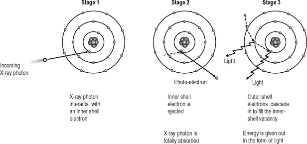
The photoelectric effect is a pure absorption interaction predominating with low-energy photons (see Fig. 2.10).
Summary of the stages in the photoelectric effect
1. The incoming X-ray photon interacts with a bound inner-shell electron of the tissue atom.
2. The inner-shell electron is ejected with considerable energy (now called a photoelectron) into the tissues and will undergo further interactions (see below).
3. The X-ray photon disappears having deposited all its energy; the process is therefore one of pure absorption.
4. The vacancy which now exists in the inner electron shell is filled by outer-shell electrons dropping from one shell to another.
5. This cascade of electrons to new energy levels results in the emission of excess energy in the form of light or heat.
6. Atomic stability is finally achieved by the capture of a free electron to return the atom to its neutral state.
7. The high-energy ejected photoelectron behaves like the original high-energy X-ray photon, undergoing many similar interactions and ejecting other electrons as it passes through the tissues. It is these ejected high-energy electrons that are responsible for the majority of the ionization interactions within tissue, and the possible resulting damage attributable to X-rays.
Important points to note
• The X-ray photon energy needs to be equal to, or just greater than, the binding energy of the inner-shell electron to be able to eject it.
• As the density (atomic number, Z) increases, the number of bound inner-shell electrons also increases. The probability of photoelectric interactions occurring is ∝ Z3. Lead has an atomic number of 82 and is therefore a good absorber of X-rays — hence its use in radiation protection (see Ch. 8). The approximate atomic number for soft tissue is 7 (Z3 = 343) and for bone is 12 (Z3 = 1728) — hence their obvious difference in radiodensity, and the contrast between the different tissues seen on radiographs (see Ch. 24).
• This interaction predominates with low energy X-ray photons — the probability of photoelectric interactions occurring is ∝ 1/kV3. This explains why low kV X-ray equipment results in high absorption (dose) in the patient’s tissues, but provides good contrast radiographs.
• The overall result of the interaction is ionization of the tissues.
• Intensifying screens, described in Chapter 6, function by the photoelectric effect — when exposed to X-rays, the screens emit their excess energy as light, which subsequently affects the film emulsion.
Compton effect
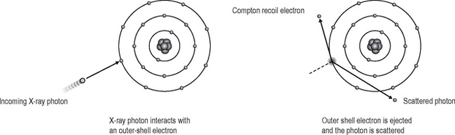
The Compton effect is an absorption and scattering process predominating with higher-energy photons (see Fig. 2.11).
Summary of the stages in the Compton effect
1. The incoming X-ray photon interacts with a free or loosely bound outer-shell electron of the tissue atom.
2. The outer-shell electron is ejected (now called the Compton recoil electron) with loss of some of the energy of the incoming photon, i.e. there is some absorption. The ejected electron then undergoes further ionizing interactions within the tissues (as before).
3. The remainder of the incoming photon energy is deflected or scattered from its original path as a scattered photon.
4. The scattered photon may then:
5. Atomic stability is again achieved by the capture of another free electron.
Important points to note
• The energy of the incoming X-ray photon is much greater than the binding energy of the outer-shell or free electron.
• The incoming X-ray photon cannot distinguish between one free electron and another — the interaction is not dependent on the atomic number (Z). Thus, this interaction provides very little diagnostic information as there is very little discrimination between different tissues on the final radiograph.
• This interaction predominates with high X-ray photon energies. This explains why high-voltage X-ray sets result in radiographs with poor contrast.
• The energy of the scattered photon (Es) is always less than the energy of the incoming photon (E), depending on the energy given to the recoil electron (e):

• Scattered photons can be deflected in any direction, but the angle of scatter (θ) depends on their energy. High-energy scattered photons produce forward scatter; low-energy scattered photons produce back scatter (see Fig. 2.12).
• Forward scatter may reach the film and degrade the image, but can be removed by using an anti-scatter grid (see Ch. 14).
• The overall result of the interaction is ionization of the tissues.
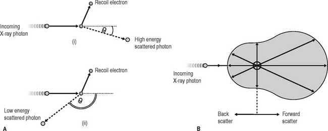
Fig. 2.12A Diagram showing the angle of scatter θ with (i) high- and (ii) low-energy scattered photons. B Typical scatter distribution diagram of a 70 kV X-ray set. The length of any radius from the source of scatter indicates the relative amount of scatter in that direction. At this voltage, the majority of scatter is in a forward direction.