Chapter 1 The radiographic image
INTRODUCTION
The use of X-rays is an integral part of clinical dentistry, with some form of radiographic examination necessary on the majority of patients. As a result, radiographs are often referred to as the clinician’s main diagnostic aid.
The range of knowledge of dental radiography and radiology thus required can be divided conveniently into four main sections:
• Basic physics and equipment — the production of X-rays, their properties and interactions which result in the formation of the radiographic image
• Radiation protection — the protection of patients and dental staff from the harmful effects of X-rays
• Radiography — the techniques involved in producing the various radiographic images
• Radiology — the interpretation of these radiographic images.
Understanding the radiographic image is central to the entire subject. This chapter provides an introduction to the nature of this image and to some of the factors that affect its quality and perception.
NATURE OF THE RADIOGRAPHIC IMAGE
Traditionally the image was produced by the X-rays passing through an object (the patient) and interacting with the photographic emulsion on a film, which resulted in blackening of the film. Film is gradually being replaced by a variety of digital sensors with the image being created in a computer. Those parts of the digital sensor that have been hit by X-rays appear black in the computer-generated image. The extent to which the emulsion or the computer-generated image is blackened depends on the number of X-rays reaching the film or sensor (either device can be referred to as an image receptor), which in turn depends on the density of the object.
However the final image is captured, it can be described as a two-dimensional picture made up of a variety of black, white and grey superimposed shadows and is thus sometimes referred to as a shadowgraph (see Fig. 1.1).
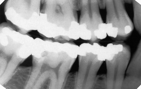
Fig. 1.1 A typical dental radiograph. The image shows the various black, grey and white radiographic shadows.
Understanding the nature of the shadowgraph and interpreting the information contained within it requires a knowledge of the following:
• The three-dimensional anatomical tissues
• The limitations imposed by a two-dimensional picture and superimposition.
The radiographic shadows
The amount the X-ray beam is stopped (attenuated) by an object determines the radiodensity of the shadows:
• The white or radiopaque shadows on an image represent the various dense structures within the object which have totally stopped the X-ray beam.
• The black or radiolucent shadows represent areas where the X-ray beam has passed through the object and has not been stopped at all.
• The grey shadows represent areas where the X-ray beam has been stopped to a varying degree.
The final shadow density of any object is thus affected by:
• The specific type of material of which the object is made
• The thickness or density of the material
• The intensity of the X-ray beam used
• The position of the object in relation to the X-ray beam and image receptor
The effect of different materials, different thicknesses/densities, different shapes and different X-ray beam intensities on the radiographic image shadows are shown in Figures 1.2-1.5.
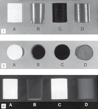
Fig. 1.2 (i) Front view and (ii) plan view of various cylinders of similar shape but made of different materials: A plaster of Paris, B hollow plastic, C metal, D wood. (iii) Radiographs of the cylinders show how objects of the same shape, but of different materials, produce different radiographic images.
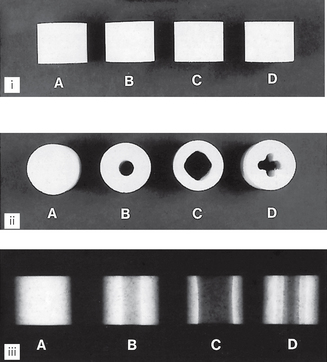
Fig. 1.3 (i) Front view of four apparently similar cylinders made from plaster of Paris. (ii) Plan view shows the cylinders have varying internal designs and thicknesses. (iii) Radiographs of the apparently similar cylinders show how objects of similar shape and material, but of different densities, produce different radiographic images.
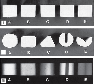
Fig. 1.4 (i) Front view of five apparently similar cylinders made from plaster of Paris. (ii) Plan view shows the objects are in fact different shapes. (iii) Radiographs show how objects of different shape, but made of the same material, produce different radiographic images.
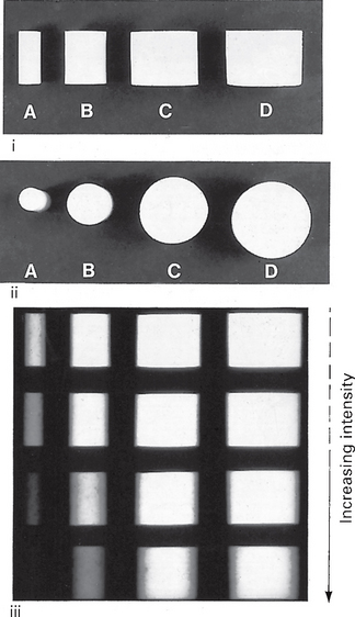
Fig. 1.5 (i) Front view and (ii) plan view of four cylinders made from plaster of Paris but of different diameters. (iii) Four radiographs using different intensity X-ray beams show how increasing the intensity of the X-ray beam causes greater penetration of the object with less attenuation, hence the less radiopaque (white) shadows of the object that are produced, particularly of the smallest cylinder.
The three-dimensional anatomical tissues
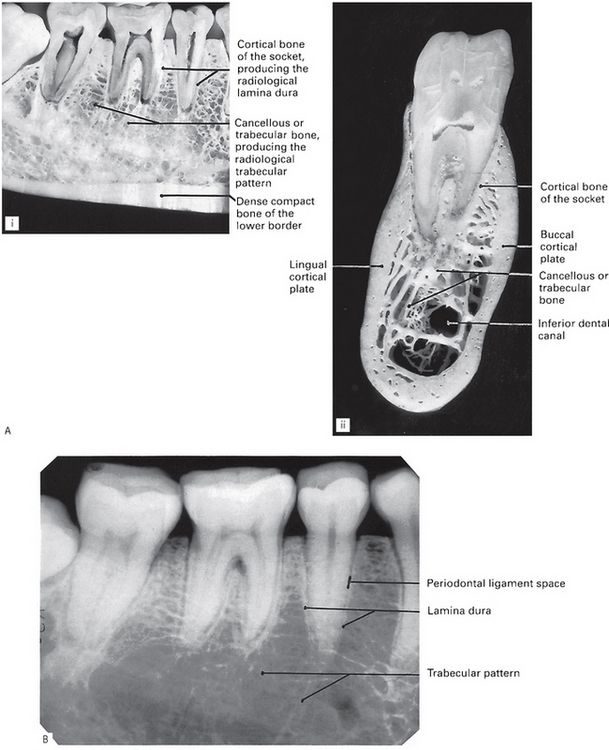
The shape, density and thickness of the patient’s tissues, principally the hard tissues, must also affect the radiographic image. Therefore, when viewing two-dimensional radiographic images, the three-dimensional anatomy responsible for the image must be considered (see Fig. 1.6). A sound anatomical knowledge is obviously a prerequisite for radiological interpretation (see Ch. 20).
The limitations imposed by a two-dimensional image and superimposition
The main limitations of viewing the two-dimensional image of a three-dimensional object are:
• Appreciating the overall shape of the object
• Superimposition and assessing the location and shape of structures within an object.
Appreciating the overall shape
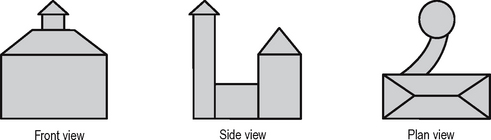
To visualize all aspects of any three-dimensional object, it must be viewed from several different positions. This can be illustrated by considering an object such as a house, and the minimum information required if an architect is to draw all aspects of the three-dimensional building in two dimensions (see Fig. 1.7). Unfortunately, it is only too easy for the clinician to forget that teeth and patients are three-dimensional. To expect one radiograph to provide all the required information about the shape of a tooth or patient is like asking the architect to describe the whole house from the front view alone.
Superimposition and assessing the location and shape of structures within an object
The shadows cast by different parts of an object (or patient) are superimposed upon one another on the final radiograph. The image therefore provides limited or even misleading information as to where a particular internal structure lies, or to its shape, as shown in Figure 1.8.
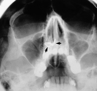
Fig. 1.8 Radiograph of the head from the front (an occipitomental view) taken with the head tipped back, as described later in Chapter 14. This positioning lowers the dense bones of the base of the skull and raises the facial bones so avoiding superimposition of one on the other. A radiopaque (white) object (arrowed) can be seen apparently in the base of the right nasal cavity.
In addition, a dense radiopaque shadow on one side of the head may overlie an area of radiolucency on the other, so obscuring it from view, or a radiolucent shadow may make a superimposed radiopaque shadow appear less opaque.
One clinical solution to these problems is to take two views, at right angles to one another (see Figs 1.9 and 1.10). Unfortunately, even two views may still not be able to provide all the desired information for a diagnosis to be made (see Fig. 1.11).
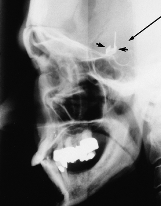
Fig. 1.9 Radiograph of the head from the side (a true lateral skull view) of the same patient shown in Figure 1.8. The radiopaque (white) object (arrowed) now appears intracranially just above the skull base. It is in fact a metallic aneurysm clip positioned on an artery in the Circle of Willis at the base of the brain. The long black arrow indicates the direction of the X-ray beam required to produce the radiograph in Figure 1.8, illustrating how the clip appears to be in the nose.
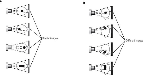
Fig. 1.10 Diagrams illustrating the limitations of a two-dimensional image: A Posteroanterior views of a head containing a variable mass. The mass appears as a similar sized opaque image on the radiograph, providing no differentiating information on its position or shape. B The side view provides a possible solution to the problems illustrated in A.
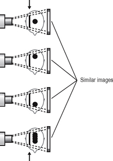
Fig. 1.11 Diagrams illustrating the problems of superimposition. Lateral views of the same masses shown in Figure 1.10 but with an additional radiodense object superimposed (arrowed). This produces a similar image in each case with no evidence of the mass. The information obtained previously is now obscured and the usefulness of using two views at right angles is negated.
These limitations of the conventional radiographic image have very important clinical implications and may be the underlying reason for a negative radiographic report. The fact that a particular feature or condition is not visible on one radiograph does not mean that the feature or condition does not exist, merely that it cannot be seen. Many of the recently developed alternative and specialized imaging modalities described in Chapter 19 have been designed to try to overcome these limitations
QUALITY OF THE RADIOGRAPHIC IMAGE
Overall image quality and the amount of detail shown on a radiographic image depend on several factors, including:
• Contrast — the visual difference between the various black, white and grey shadows
• Image geometry — the relative positions of the film, object and X-ray tubehead
These factors are in turn dependent on several variables, relating to the density of the object, the type of image receptor and the X-ray equipment. They are discussed in greater detail in Chapter 18. However, to introduce how the geometrical accuracy and detail of the final image can be influenced, two of the main factors are considered below.
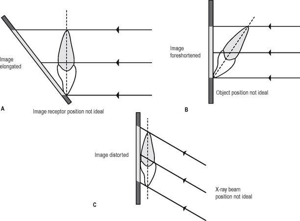
Positioning of the image receptor, object and X-ray beam
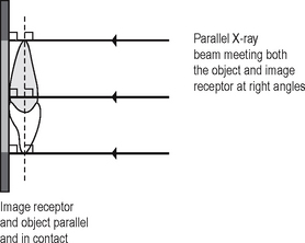
The position of the X-ray beam, object and image receptor needs to satisfy certain basic geometrical requirements. These include:
• The object and the image receptor should be in contact or as close together as possible
• The object and the image receptor should be parallel to one another
• The X-ray tubehead should be positioned so that the beam meets both the object and the image receptor at right angles.
These ideal requirements are shown diagrammatically in Figure 1.12. The effects on the final image of varying the position of the object, image receptor or X-ray beam are shown in Figure 1.13.
X-RAY BEAM CHARACTERISTICS
The ideal X-ray beam used for imaging should be:
• Sufficiently penetrating, to pass through the patient and react with the film emulsion or digital sensor and produce good contrast between the different shadows (Fig. 1.14)
• Parallel, i.e. non-diverging, to prevent magnification of the image
• Produced from a point source, to reduce blurring of the edges of the image, a phenomenon known as the penumbra effect.
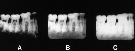
Fig. 1.14 Film-captured radiographs of the same area showing variation in contrast — the visual difference in the black, white and grey shadows due to the penetration of the X-ray beam. A Increased exposure (overpenetration). B Normal exposure. C Reduced exposure (underpenetration).
These ideal characteristics are discussed further in Chapter 5.
PERCEPTION OF THE RADIOGRAPHIC IMAGE
The verb to perceive means to apprehend with the mind using one or more of the senses. Perception is the act or faculty of perceiving. In radiology, we use our sense of sight to perceive the radiographic image, but, unfortunately, we cannot rely completely on what we see. The apparently simple black, white and grey shadowgraph is a form of optical illusion (from the Latin illudere, meaning to mock). The radiographic image can thus mock our senses in a number of ways. The main problems can be caused by the effects of:
Effect of partial images
As mentioned already, the radiographic image only provides the clinician with a partial image with limited information in the form of different density shadows. To complete the picture, the clinician fills in the gaps. Unfortunately, not all clinicians necessarily do this in the same way and may therefore arrive at different conclusions. Three non-clinical examples are shown in Figure 1.15. Clinically, our differing perceptions may lead to different diagnoses.
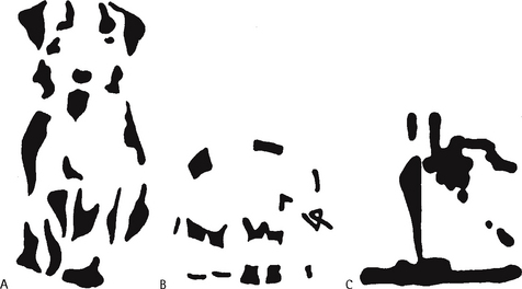
Fig. 1.15 The problem of partial images requiring the observer to fill in the missing gaps. Look at the three non-clinical pictures and what do you perceive? The objects shown are A a dog, B an elephant and C a steam ship. We all see the same partial images, but we don’t necessarily perceive the same objects. Most people perceive the dog, some perceive the elephant while only a few perceive the ship and take some convincing that it is there. Interestingly, once observers have perceived the correct objects, it is impossible to look at the pictures again in the future without perceiving them correctly.
(Figures from: Coren S, Porac C, Ward LM 1979 Sensation and perception. Harcourt Brace and Company, reproduced by permission of the publisher.)
Effect of contrast
The apparent density of a particular radiographic shadow can be affected considerably by the density of the surrounding shadows. In other words, the contrast between adjacent structures can alter the perceived density of one or both of them (see Fig. 1.16). This is of particular importance in dentistry, where metallic restorations produce densely white radiopaque shadows that can affect the apparent density of the adjacent tooth tissue. This is discussed again in Chapter 21 in relation to caries diagnosis.
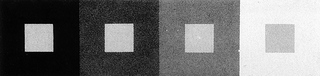
Fig. 1.16 The effect of contrast. The four small inner squares are in reality all the same grey colour, but they appear to be different because of the effect of contrast. When the surrounding square is black, the observer perceives the inner square to be very pale, while when the surrounding square is light grey, the observer perceives the inner square to be dark.
(Figure from: Cornsweet TN 1970 Visual perception. Harcourt Brace and Company, reproduced by permission of the publisher.)
Effect of context
The environment or context in which we see an image can affect how we interpret that image. A non-clinical example is shown in Figure 1.17. In dentistry, the environment that can affect our perception of radiographs is that created by the patient’s description of the complaint. We can imagine that we see certain radiographic changes, because the patient has conditioned our perceptual apparatus.
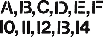
Fig. 1.17 The effect of context. If asked to read the two lines shown here most, if not all, observers would read the letters A,B,C,D,E,F and then the numbers 10,11,12,13,14. Closer examination shows the letter B and the number 13 to be identical. They are perceived as B and 13 because of the context (surrounding letters or numbers) in which they are seen.
(Figure from: Coren S, Porac C, Ward LM 1979 Sensation and perception. Harcourt Brace and Company, reproduced by permission of the publisher.)
These various perceptual problems are included simply as a warning that radiographic interpretation is not as straightforward as it may at first appear.
COMMON TYPES OF DENTAL RADIOGRAPHS
The various radiographic images of the teeth, jaws and skull are divided into two main groups:
• Intraoral — the image receptor is placed inside the patient’s mouth, including:
• Extraoral — the image receptor is placed outside the patient’s mouth, including:
These various radiographic techniques are described later, in the chapters indicated. The approach and format adopted throughout these radiography chapters are intended to be straightforward, practical and clinically relevant and are based upon the essential knowledge required by clinicians. This includes: