Chapter 31 The temporomandibular joint
INTRODUCTION
The temporomandibular joint (TMJ) is one of the most difficult areas to investigate radiographically. This fact is underlined by the many types of investigations that have been developed over the years. Several plain radiographic projections and various modern imaging modalities are used for showing different parts of the complex joint anatomy. The clinical problems are complicated by the broad spectrum of conditions that can affect the joints, which can present with very similar signs and symptoms, and by prolonged searches for objective signs to explain TMJ pain dysfunction.
From the investigative point of view the knowledge required by clinicians includes:
NORMAL ANATOMY
The basic components of the TMJ include:
• The mandibular component, i.e. the head of the condyle
• The temporal component, i.e. the glenoid fossa and articular eminence
• The capsule surrounding the joint (see Figs 31.1 and 31.2).
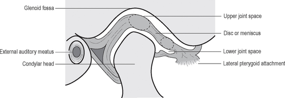
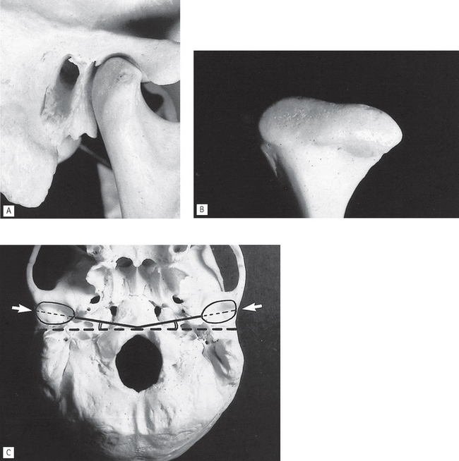
Fig. 31.2 A The bony components of the joint from the side. B The head of the condyle from the anterior aspect. C The base of the skull from below. The glenoid fossae (arrowed) and their angulation to the coronal plane have been drawn in.
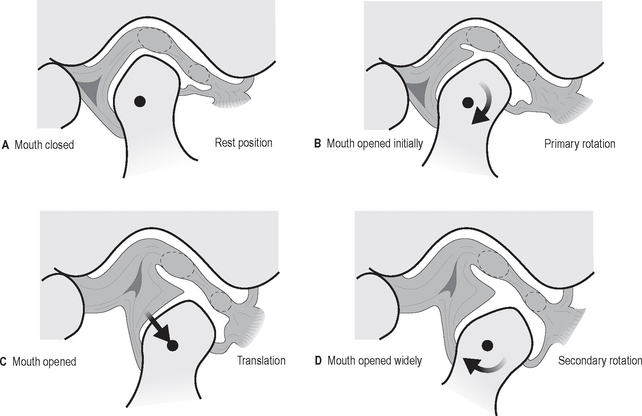
In addition to this knowledge of the static anatomy, clinicians need to be aware of the types and range of joint movements which result in the condyles moving downwards and forwards when patients open their mouths. These include:
• Hinge or rotation of the condyle within the fossa
• Translation or excursive movement of the condyle down the articular eminence. The disc being attached to the condyle also moves forwards as shown in Figure 31.3.
INVESTIGATIONS
Modern imaging of the TMJ is dependent on the facilities available but could include:
Previously described transorbital and trancranial views are now seldom used and are only of historical interest.
Dental panoramic radiography
Technique summary (see Ch. 17 for details)
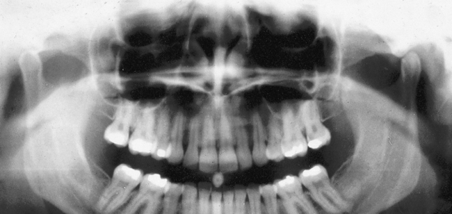
Conventional panoramics usually image both condylar heads, although to guarantee this the technique can be modified by raising the X-ray tubehead and cassette carriage assembly to a slightly higher level in relation to the patient (so-called high panoramic as shown in Fig. 31.4).
Panoramic TMJ programmes
Main indications
The main clinical indications are the same as for a conventional panoramic radiograph. If the equipment includes specific TMJ programmes these should be regarded as the views of choice as additional information can be provided when the mouth is opened.
Technique summary
The technique can be summarized as follows:
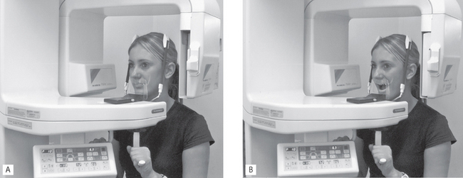
• The patient is positioned with their Frankfurt plane angled 5 degrees downwards within a panoramic unit with their mouth closed but using a special nose/chin support as shown in Figure 31.5A instead of the bite-peg
• The head is accurately positioned using the light beam markers and immobilized using the temple supports
• The distance from the external auditory meatus to the canine light is measured and the anteroposterior position of the chin support adjusted manually to ensure that the condyles appear in the middle of the image
• During the exposure, first the left and then the right condyle is imaged in the closed position
• The equipment automatically returns to the start position
• The patient is instructed to open the mouth, as shown in Figure 31.5B
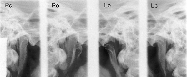
• The left and right condyles are then exposed in the open position and the resultant image is shown in Figure 31.6.
Transpharyngeal radiography
Technique and positioning
This projection can be taken with a dental X-ray set and an extraoral cassette. The technique can be summarized as follows:
1. The patient holds the cassette against the side of the face over the TMJ of interest. The film and the mid-sagittal plane of the head are parallel. The patient’s mouth is open and a bite-block is inserted for stability.
2. The X-ray tubehead is positioned in front of the opposite condyle and beneath the zygomatic arch. It is aimed through the sigmoid notch, slightly posteriorly, across the pharynx at the condyle under investigation, as shown in Figure 31.7. Usually this view is taken of both condyles to allow comparison.
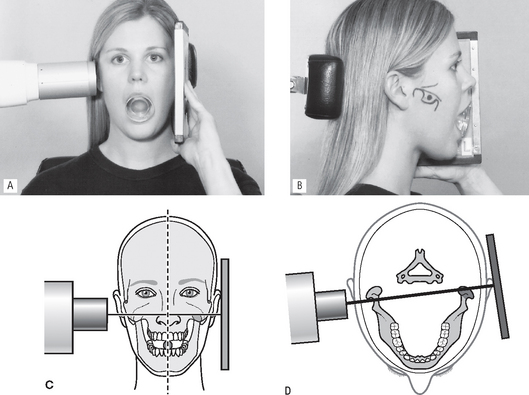
Fig. 31.7 A Positioning for the left transpharyngeal — the patient is holding the film against the left TMJ, the mouth is open and the X-ray beam is aimed across the pharynx. B The side of the face with various anatomical structures — the zygomatic arch, condyle, sigmoid notch and coronoid process — drawn in to clarify the centring point of the X-ray beam which is marked. C Diagram of the positioning from the front showing the film parallel to the mid-sagittal plane and the X-ray beam aimed across the pharynx. D Diagram of the positioning from above, showing the X-ray beam aimed slightly posteriorly across the pharynx.
Diagnostic information
The information provided includes:
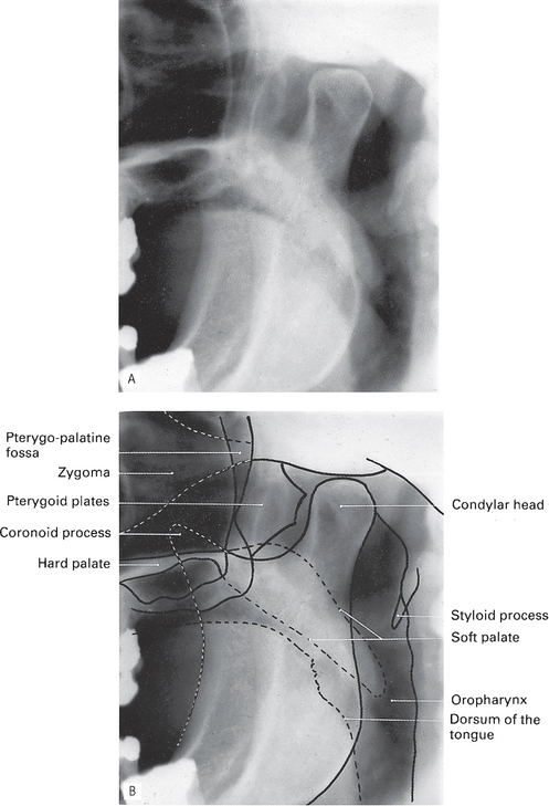
• The shape of the head of the condyle and the condition of the articular surface from the lateral aspect (Fig. 31.8)
Multidirectional tomography
Modern multidirectional tomographic equipment such as the Scanora® unit, described in Chapter 16 enables high resolution tomographic images of the bony elements of the TMJ to be obtained in both the near-sagittal and coronal planes.
Technique summary
The procedure can be summarized as follows:
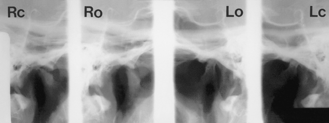
• An initial computer-controlled sagittal orientation programme is selected, which enables the correct angulation for ideal cross-sectional imaging to be assessed, by taking relatively thick (16 mm) tomographic views of the TMJ at four different angles (see Figs 31.9 and 31.10).
• The optimal angulation is chosen, fed into the unit and narrow (2 or 4 mm), detailed, computer-controlled, spiral tomographic cross-sectional slices of the joint are produced, as shown in Figure 31.11A.
• Similarly, coronal orientation and detailed tomographic programmes can be selected to produce narrow (6 mm) coronal tomographic slices, as shown in Figure 31.11B.
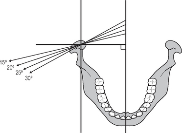
Fig. 31.9 Diagram showing the different angulations of the Scanora® TMJ orientation programme, enabling the correct angulation for detailed cross-sectional tomography to be determined.
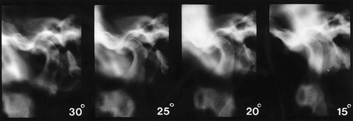
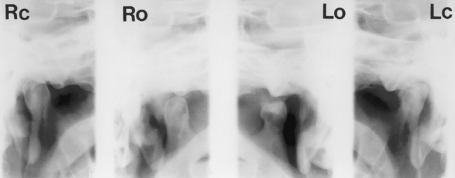
Fig. 31.10 Examples of the 16 mm thick tomographs taken at the four different angulations of the Scanora® orientation programme. The 25° angulation was considered the most satisfactory and used to produce the detailed tomographs shown in Figure 31.11A.
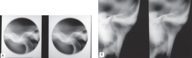
Fig. 31.11 A Two 4-mm thick, near-sagittal, detailed spiral tomographic slices of the left TMJ using the 25° orientation programme. Note the small round collimated beam that is used to restrict the radiation to the exact area of interest. B Two 6-mm thick coronal tomographs of the same left condylar head.
Diagnostic information
Cone beam CT
Cone beam CT (CBCT) described in Chapter 19 is increasingly being used to image the bony elements of the TMJ as shown in Figures 31.12 and 31.13. As with multidirectional tomography, sectional or slice images of all aspects of the joints are produced, but in addition, using appropriate software, 3-D images can be created.
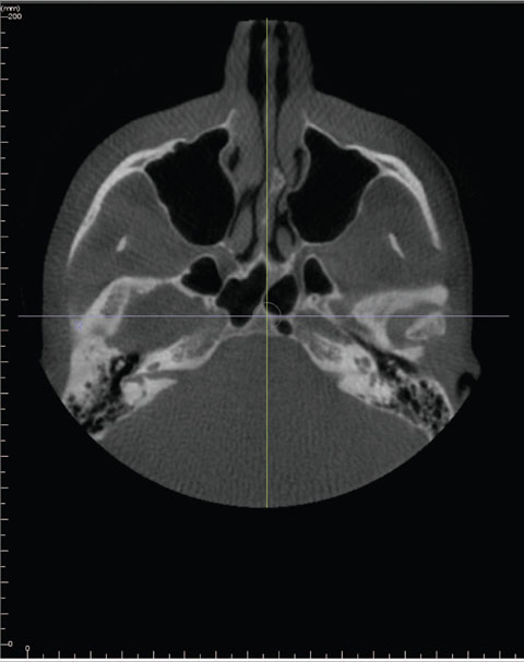
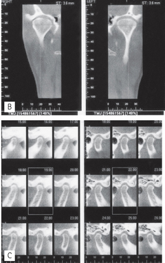
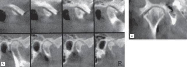
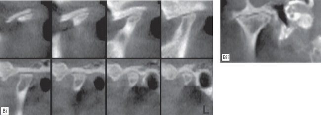
Fig. 31.12 A Axial, B coronal and C various near-sagittal images of normal right and left TMJs obtained using the I-CAT® cone beam CT.
(Reproduced with the kind permission of Imaging Sciences International, Inc.)
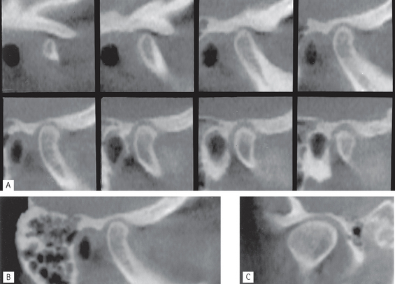
Fig. 31.13 A and B series of near-sagittal and C coronal images of a normal right TMJ obtained using the NewTom® cone beam CT.
(Kindly provided by Prof K. Tsiklakis.)
Main indications
The main clinical indications are the same as for multidirectional tomography and include:
• Full assessment of the whole of the joint to determine the presence and site of any bone disease or abnormality
• To investigate the condyle and articular fossa when the patient is unable to open the mouth
• Assessment of fractures of the condylar head and articular fossa and intracapsular fractures.
Magnetic resonance (MR)
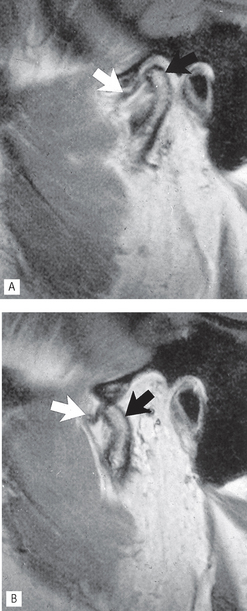
Magnetic resonance imaging described in Chapter 19 is now established as one of the more useful investigations of the bony and soft tissue elements of the TMJ. It is particularly useful for determining the position and form of the disc when the mouth is both open and closed (see Fig. 31.14). As mentioned in Chapter 19, cineloop or pseudodynamic echo sequences are generally used for TMJ imaging:
Computed tomography (CT)
Computed tomography described in Chapter 19, like ordinary tomography, provides sectional or slice images of the joint. The advantages of CT are that it can produce images of the hard and soft tissues in the joint, including the disc, in different planes.
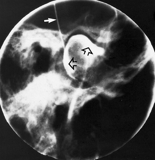
Arthrography
Technique (Fig. 31.15)
This can be summarized as follows:
1. Non-ionic aqueous contrast medium (e.g. iopamidol-Niopam® 370) is injected carefully into the lower joint space, using fluoroscopy to aid the accurate positioning of the needle
2. The primary record is obtained ideally using video-recorded fluorography or cinefluorography which allows imaging of the joint components as they move. Only the lateral aspects of the joints are seen
3. Thin-section, multidirectional (e.g. hypocycloidal) tomography of the joint can also be performed if required, to provide information on the medial and lateral aspects of the joint. Typically, five or six slices, 2–3 mm apart, are used with the patient’s mouth open and closed
4. If further information is required, the contrast medium can be introduced into the upper joint space and the investigation repeated.
Diagnostic information
The information provided includes:
• Dynamic information on the position of the joint components and disc as they move in relation to one another
• Static images of the joint components with the mouth closed and with the mouth open. Any anterior or anteromedial displacement of the disc can be observed
• The integrity of the disc, i.e. the presence of any perforations.
Note: Outlining the lower joint space usually provides the more useful information on the disc.
Arthroscopy
Arthroscopy gives direct visualization of the TMJ and allows certain interventional procedures to be performed; these include:
Arthroscopy is usually considered as the last line of investigation before full surgical exploration of the joint is carried out.
MAIN PATHOLOGICAL CONDITIONS AFFECTING THE TMJ
The main pathological conditions that can affect the TMJ include:
• TMJ pain dysfunction syndrome (myofascial pain dysfunction syndrome)
• Osteoarthritis (osteoarthrosis)
TMJ (myofascial) pain dysfunction syndrome
This is the most common clinical diagnosis applied to patients with pain in the muscles of mastication, often worst in the early morning and evening, with occasional clicking and stiffness. The aetiology is said to include anxiety or depression, malocclusion, or muscle spasm.
Main radiographic features
• Normal condylar head shape and articular surface
• Possible increase or reduction in the overall size of the joint space — an increase in the size of the joint space is only indicative of inflammation
• Possible displacement of the condylar head anteriorly or posteriorly in the glenoid fossa when the mouth is closed and the teeth are in occlusion
Note In their booklet Making Best Use of a Department of Clinical Radiology 5th edn, published in 2003 the Royal College of Radiologists in the UK state that in relation to TMJ dysfunction, radiographs ‘do not often add information as the majority of temporomandibular joint problems are due to soft tissue dysfunction rather than bony changes, which appear late and are often absent in the acute phase’.
Internal derangements
Symptoms include clicking which may be painful, pain from the joint and/or musculature, trismus and hesitation of movement and locking usually with failure of opening. Conventional radiography may have revealed an alteration in the position of the head of the condyle, implying an abnormality in disc position. MRI is the investigation of choice to show:
Osteoarthritis
This degenerative arthrosis increases in incidence with age and commonly causes pain in the stressbearing joints, such as the hips and spine. It is now thought to be a systemic disease, or a complication of internal derangement of a joint, and stress merely causes the affected joint to be painful. Radiographic signs of osteoarthritis of the TMJ are often seen in the elderly, but are frequently of no clinical significance. Symptoms, if they occur, can include painful crepitus and trismus and are usually persistent.
Main radiographic features (see Figs 31.16-31.18)
• Osteophyte (bony spur) formation on the anterior aspect of the articular surface of the condylar head. The radiological appearance of small osteophyte formation is often referred to as lipping; extensive osteophyte formation is referred to as beaking
• Flattening of the head of the condyle on the anterosuperior margin
• Subchondral sclerosis of the condylar head which becomes dense and more radiopaque — a process sometimes referred to as eburnation
• A normal outline to the glenoid fossa though it may also become sclerotic
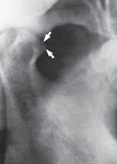
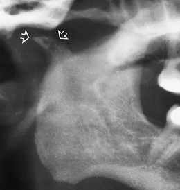
Fig. 31.16 Transpharyngeal of a right condyle showing advanced osteoarthritic change with pronounced anterior osteophyte formation (beaking) (arrowed).
Rheumatoid arthritis
Rheumatoid arthritis is a generalized, chronic inflammatory, connective tissue disease affecting many joints. TMJ involvement can be found, particularly in severe rheumatoid arthritis, but even then TMJ symptoms are usually minor.
Main radiographic features (see Figs 31.19-31.21)
• Flattening of the head of the condyle
• Erosion and destruction of the articular surface of the head of the condyle which may be extensive causing the outline to become irregular
• Occasional osteophyte formation on the condylar head
• Hollowing of the glenoid fossa
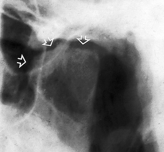
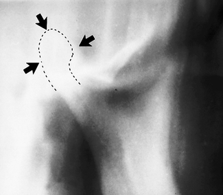
Fig. 31.19 Transpharyngeal of a left condyle showing the typical erosion and destruction of the articular surface (arrowed) caused by severe rheumatoid arthritis.
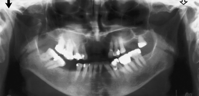
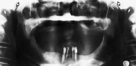
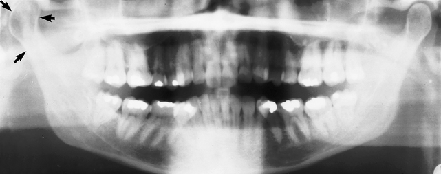
Fig. 31.20 Panoramic radiograph showing advanced rheumatoid arthritic change in both right and left condyles in a 75-year-old woman with widespread joint involvement. The right (solid arrow) shows marked flattening while the left (open arrow) shows erosion of the articular surface. Despite these pronounced changes the patient was symptom-free.
Juvenile rheumatoid arthritis (Still’s disease)
The radiographic features of juvenile rheumatoid arthritis are similar to the adult disease. In severe cases, the disease may cause interference with normal condylar growth producing micrognathia, or it may result in TMJ ankylosis.
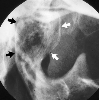
Ankylosis
True ankylosis, i.e. fusion of the bony elements of the joint (see Fig. 31.22), is uncommon but is usually the result of:
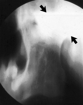
Fig. 31.22 Sagittal section tomograph of the left TMJ showing complete ankylosis and bony fusion of the condyle and glenoid fossa (arrowed).
Tomography, cone beam CT or CT are the investigations of choice because of the obvious problems of opening the mouth.
Main radiographic features
• Little or no evidence of a joint space
• Bony fusion between the head of the condyle and the glenoid fossa with total loss of the normal anatomical outlines
• Associated evidence of condylar neck hypoplasia and mandibular underdevelopment on the affected side producing asymmetry, if the ankylosis precedes completion of mandibular growth. A prominent antegonial notch on the affected side is often evident.
Tumours
Benign or malignant tumours develop occasionally in the head of the condyle. The radiographic features depend on the type and nature of the tumour involved, but there is usually an alteration in the shape of the condylar head. Typical examples include osteoma, chondroma (see Fig. 31.23) and chondrosarcoma.
Fractures and trauma
Fractures of the condylar necks are common after a blow to the chin (see Ch. 30). Very occasionally with this type of injury the condylar neck does not fracture but the head of the condyle either fractures, a so-called intra-capsular fracture (see Fig. 31.24) or is forced upwards, through the glenoid fossa into the middle cranial fossa (see (Fig. 31.25). Tomography, cone beam CT or CT will demonstrate the extent of any injury. Trauma can also result in unilateral or bilateral dislocation (see Fig. 31.26).
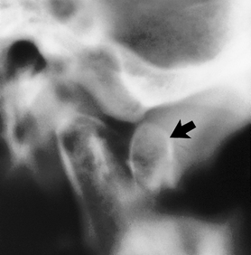
Fig. 31.24 Near-sagittal spiral tomographic slice showing an intracapsular fracture of the head of a right condyle. The anteriorly displaced fractured fragment of the head is arrowed.
Developmental anomalies
Developmental defects affecting the TMJ are usually investigated using conventional radiography. They can be divided into:
• Condylar hypoplasia (unilateral or bilateral) (see Fig. 31.27)
• Condylar hyperplasia (unilateral or bilateral) (see Fig. 31.28)
• Bifid condyle (see Fig. 25.30)
• Defects associated with specific disease or syndromes, for example:
FOOTNOTE
The bony abnormalities illustrated are often detected as incidental findings on panoramic radiographs taken for some other clinical condition. For those patients with specific signs and symptoms relating to the TMJ the type of investigation chosen will depend on the history, the clinical presentation and the facilities available. Knowledge of the respective merits and limitations of the different investigations allows the clinician to use the most appropriate for each patient.