Pneumothorax
Pneumothorax is discussed in detail in Chapter 6. (See the extensive figures in that chapter.) Pneumothorax can occur outside of the setting of trauma. Spontaneous pneumothorax and iatrogenic injury from mechanical ventilation or procedural complications (e.g., during central venous catheter placement) may occur. Pneumothorax is characterized by an absence of normal lung vascular markings in the zone of pneumothorax. The resulting lung field appears extremely lucent or dark. The pleural line of the injured lung is often visible on x-ray and should be carefully sought. This line must be distinguished from skin folds, objects outside of the patient, and the curved cortices of ribs, which may have a similar appearance. In each of these cases, and unlike the true pleural line of a pneumothorax, lung markings are visible beyond the suspect line. In addition, skin folds are usually a sharply defined line on one side but not on the other. In contrast, the pleural surface usually appears sharply defined on both sides. The medial border of the scapula should be identified explicitly to avoid confusing this line with the pleural line of a pneumothorax.
Subcutaneous air (Figure 5-153; see also Figure 5-158) can be associated with pneumothorax and should be sought as an additional clue. Subcutaneous air appears more lucent (dark) than surrounding soft tissues. Air may track into the axilla and neck and sometimes outline skeletal muscle fibers in exquisite detail. Rib fractures may be seen, suggesting occult trauma or spontaneous fractures related to osteopenia, cough, or malignancy.
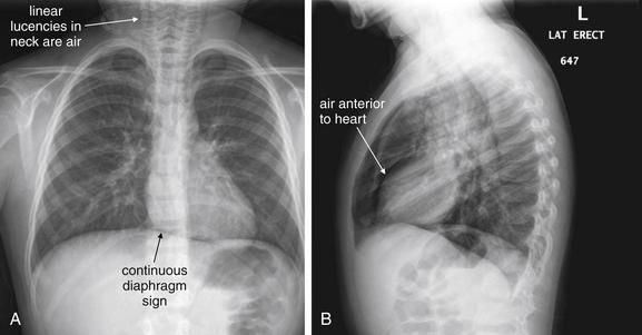
Figure 5-153 Pneumopericardium.
A, Posterior-anterior (PA) chest x-ray. B, Lateral chest x-ray. This 8-year-old female presented with acute onset of coughing the previous night. She was hypoxic to 90% on room air. Her chest x-ray shows evidence of pneumopericardium. Look carefully at the diaphragm on the posterior–anterior view. Normally, the diaphragm cannot be seen beneath the heart, because both structures are water density on chest x-ray. In this case, the diaphragm can be seen because a thin stripe of air in the pericardial sac separates the heart and the diaphragm. This is called the continuous diaphragm sign. A fine ribbon of lucent air also outlines the left heart border. On the lateral view, a thin stripe of air is visible as a linear lucency anterior to the heart. Linear lucencies in the neck are subcutaneous emphysema originating in the mediastinum. What happened to this patient? She likely has asthma exacerbated by a viral infection, given the hyperinflated anterior–posterior diameter of her chest on x-ray and the streaky opacities around her hilum. Coughing or bronchospasm against a closed glottis can force air into the mediastinum and pericardium.
Changes suggesting increased volume and pressure on the affected side of the chest must be carefully sought, as these are evidence of developing tension pneumothorax (see Figures 5-35 and 5-36). Deviation of the trachea to the contralateral side, mediastinal deviation, depression of the diaphragm, and a deep sulcus sign (a deep costophrenic angle; see Chapter 6) are all radiographic findings suggesting tension pneumothorax. The clinical state of the patient is the most important factor, so the patient should be assessed for signs of obstructive shock such as hypotension and tachycardia. Difficulty ventilating an intubated patient is a clinical sign of tension pneumothorax.
As described in Chapter 6, ultrasound and CT are believed to be more sensitive for pneumothorax than is chest x-ray, although the clinical importance of a small pneumothorax found by these modalities is debated.
Pneumopericardium and Pneumomediastinum
Pneumopericardium and pneumomediastinum are described in detail in Chapter 6. The radiographic appearance of air in the pericardial sac or mediastinum is a thin black line outlining the heart, often extending into the superior mediastinum (Figures 5-154 through 5-156; see also Figure 5-153). Air may be visible on both the frontal and the lateral projections. On the lateral view, a black line may be seen separating the anterior surface of the heart from fat in the retrosternal space. A continuous diaphragm sign may be seen (see Figures 5-154 through 5-156). This sign occurs when pericardial air is present beneath the heart. Normally, the upper surfaces of the right and left domes of the diaphragm (water density) are visible, silhouetted against the lung parenchyma (air density). The central surface of the diaphragm is not usually visible, as the diaphragm, pericardium, and myocardium are in physical contact and share the same density. When air is present within the pericardium, it is visible as a thin black line between the diaphragm and the inferior surface of the heart. This line of pericardial air visually connects the right and left diaphragms, creating the continuous diaphragm sign.
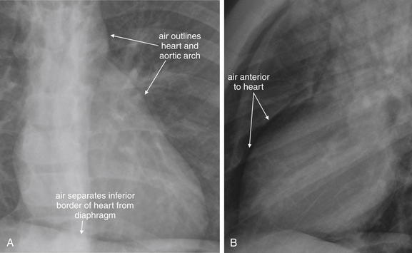
Figure 5-154 Pneumopericardium and pneumomediastinum: Close-up views from Figure 5-153. A, PA view. B, Lateral view. A, Air is visible between the inferior wall of the heart and the diaphragm, two structures that are normally indistinguishable on x-ray because they share the same density. This is called the continuous diaphragm sign. B, Air is also visible anterior to the heart on the lateral image.
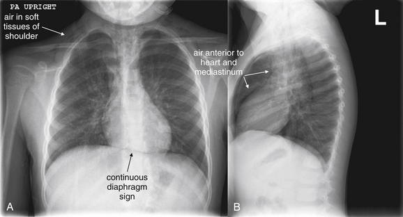
Figure 5-155 Pneumopericardium.
Same patient as Figures 5-153 and 5-154, the following day. A, Posterior-anterior (PA) chest x-ray. B, Lateral chest x-ray. The continuous diaphragm sign is still present, because of air creating contrast between the otherwise similar densities of the soft tissues of the heart and the diaphragm. Air is visible in the soft tissues of the shoulders. On the lateral x-ray, air is clearly visible anterior to the heart and along the anterior aspect of the great vessels of the mediastinum.
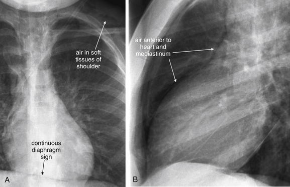
Figure 5-156 Pneumopericardium.
Close-ups from Figure 5-155. A, PA view. B, Lateral view. The continuous diaphragm sign and air in the anterior mediastinum are present. Subcutaneous air is visible within the soft tissues of the left shoulder.
Outside of the setting of trauma, pneumopericardium and pneumomediastinum can occur with barotrauma from asthma or COPD, forceful cough, repeated vomiting, or forceful valsalva, sometimes seen with cocaine or marijuana use. An associated pneumothorax should be sought during the review of the chest x-ray. The clinical history is extremely important to determine the likely source of mediastinal or pericardial air: the respiratory or gastrointestinal tract. If the source is determined to be the respiratory tract, and no large pneumothorax or persistent air leak is found, no further evaluation or treatment may be needed. However, if the source of mediastinal air is the gastrointestinal tract, as with an esophageal tear from forceful vomiting (Figure 5-157), life-threatening mediastinal infection may result. A suspected gastrointestinal source of pneumomediastinum should be further evaluated using a contrast esophagram, discussed in more detail in Chapters 4 and 9.
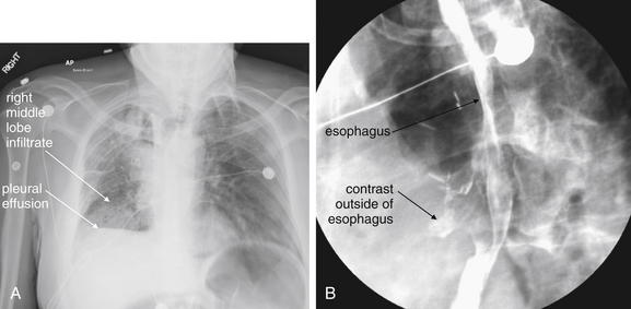
Figure 5-157 Esophageal rupture: Boerhaave’s syndrome.
This 55-year-old male has metastatic colon cancer, for which he had undergone mediastinal irradiation. The patient had an esophageal stent placed and subsequently removed 4 weeks ago for a stricture because of a metastatic lesion. He now presents with persistent coughing and emesis, tachycardia to 118, and hypoxia (pulse oximetry 83% on room air). Chest x-ray (A) demonstrates a right middle lobe infiltrate and right-sided pleural effusion. These findings are nonspecific but should be recognized in this clinical setting as potential findings of esophageal perforation, not simply pneumonia with associated pleural effusion. Unrecognized esophageal perforation may lead to mediastinitis and death. Consider the diagnosis of esophageal perforation in a patient with a history of forceful coughing or emesis, or a history of instrumentation of the esophagus. Chest x-ray may be normal or may show infiltrate, pleural effusions, pneumothorax, pneumomediastinum, or subcutaneous emphysema. A Gastrografin swallow study (B) shows contrast beyond the borders of the esophagus (arrowheads), indicating an esophageal perforation. Although less sensitive than barium swallow, Gastrografin swallow is the preferred initial study to confirm the diagnosis, as Gastrografin is less reactive than barium if leaked into the pleural space or mediastinum. If high suspicion remains after a negative Gastrografin study, barium swallow or contrast-enhanced computed tomography scan should be ordered. Broad-spectrum antibiotics and early cardiothoracic surgery consult are the mainstays of initial treatment for esophageal perforation; nonoperative therapy with tube drainage of fluid collections is an emerging therapy. The patient underwent pigtail catheter thoracostomy and esophageal stent placement in the operating room with subsequent recovery.
Occasionally, pneumomediastinum, pneumopericardium, and pneumothorax may be the result of a persistent air leak from the lung or tracheobronchial tree. Subcutaneous emphysema (Figure 5-158) may be significant in these cases and may be the patient’s presenting complaint. Increasing subcutaneous emphysema suggests a continued air leak. In the absence of trauma, air leaks of this type are often the result of surgical procedures such as thorascopic lung resections. In the presence of large amounts of subcutaneous air, the underlying lung may be difficult to evaluate because of the overlying soft-tissue artifacts. CT is sometimes necessary and allows evaluation of deeper structures regardless of the presence of soft-tissue air.
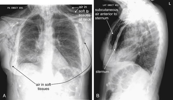
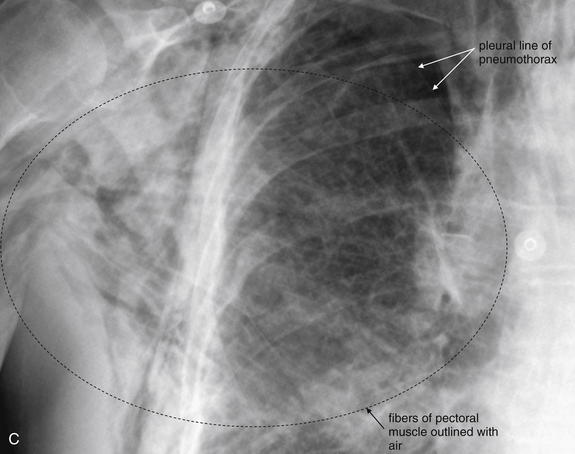
Figure 5-158 Subcutaneous emphysema.
Figure 5-156 showed subtle subcutaneous emphysema in the context of pneumopericardium. This patient presented with massive and increasing subcutaneous emphysema after a right thoracoscopic upper lobectomy for a stage I non–small cell lung cancer. Increasing subcutaneous emphysema after a procedure suggests an ongoing air leak from the respiratory tract and should prompt a search for a pneumothorax. This patient was treated with a chest tube for a right apical pneumothorax, visible in C. A, Posterior–anterior view. Air is visible in the chest wall, including the axilla, and in the subcutaneous tissues of the neck. B, Lateral view, showing dramatic subcutaneous air anterior to the sternum. C, Close-up from A shows air dissecting between fibers of the pectoral muscles. The pleural line associated with a right-sided pneumothorax is also faintly visible.
Aortic Pathology
Aortic trauma is discussed in detail in Chapter 6. Nontraumatic aortic dissection and aortic aneurysm are discussed in Chapter 7. Please refer to these chapters for dedicated discussion and figures on x-ray and CT findings of these disease processes.
Pulmonary Embolism
Risk stratification and imaging of pulmonary embolism is discussed in detail in Chapter 7. Please see Chapter 7 for extensive figures on this topic.
Masses and Neoplastic Disease
Mass lesions on chest x-ray can have numerous appearances (Figures 5-159 through 5-175). Large mass lesions may appear spiculated or rounded (see Figures 5-159 through 5-162). Some mass lesions plug large airways to the affected lung segment, resulting in volume loss (see Figures 5-163 through 5-165). Masses can appear identical to consolidation from pneumonia, and as a consequence, radiologists typically recommend a repeat chest x-ray after clinical resolution of infectious symptoms to ensure that an underlying mass lesion is not present. Small primary masses or metastatic disease may appear as solitary or multiple nodular opacities (see Figures 5-166 through 5-175). Nipple shadows may simulate nodules; this problem can be resolved by adding external markers at the location of the nipples and obtaining a repeat chest x-ray. Aggressive malignancies may result in bony destruction of adjacent ribs or vertebral bodies. Pleural and pericardial effusions may be seen in association with masses. Masses may have associated mediastinal adenopathy.
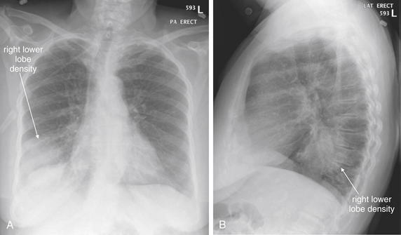
Figure 5-159 Lung mass presenting with hemoptysis.
A, Posterior-anterior (PA) chest x-ray. B, Lateral chest x-ray. This 83-year-old female presented with hemoptysis of a quarter-sized clot. Her posterior–anterior chest x-ray shows a rounded right lower lobe density. On the lateral view, this is visible in the retrocardiac space. This density measures 7.6 cm in diameter. Pneumonia, neoplasm, or abscess could have this appearance on chest x-ray. Computed tomography was performed to further delineate the pathology (Figure 5-160).
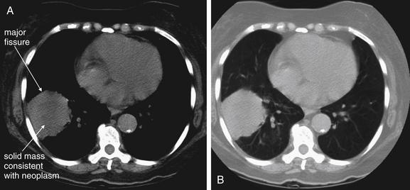
Figure 5-160 Lung mass presenting with hemoptysis.
Same patient as in Figure 5-159. Noncontrast computed tomography was performed (contrast was withheld as a consequence of the patient’s renal dysfunction) and shows a 6 by 6 cm round lesion abutting the oblique fissure (also called the major fissure) and lateral chest wall. A, Soft-tissue windows. B, Lung windows. On soft tissues windows, the center appears slightly darker, indicating lower density that may represent central necrosis. If IV contrast had been given, an area of necrosis would have failed to enhance. Infection or infarction is technically possible, but a pulmonary neoplasm is the most likely explanation for this lesion. Biopsy showed this to be a moderately differentiated squamous cell carcinoma.
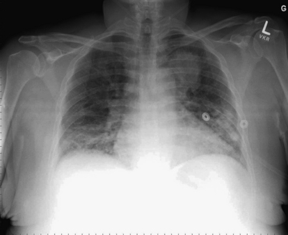
This 48-year-old with asthma and human immunodeficiency virus was brought to the emergency department by emergency medical services with dyspnea, fever, productive cough, and wheezing. Her chest x-ray shows opacities in the bilateral lower lung fields, partially obscuring the right diaphragm, compatible with pneumonia. Apparently incidentally, along the margin of the left mediastinum and aortic knob is a rounded left upper lobe opacity, concerning for a mass. The patient was treated with ceftriaxone and azithromycin for pneumonia, with resolution of her lower lung opacities, but the mass persisted. Testing for pneumocystis pneumonia and tuberculosis was negative. The mass was biopsied and was found to be adenocarcinoma.
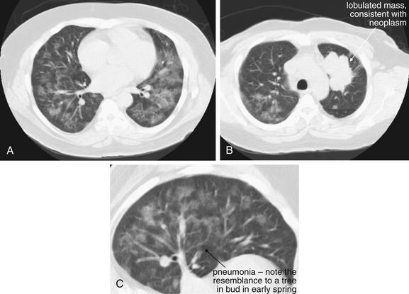
Same patient as Figure 5-161. Computed tomography was performed the same day; images are shown with lung windows. Two separate processes are present here. A, Evidence of pneumonia is present, with a “tree in bud” appearance (C, close-up). The opacities have a ground-glass appearance with lobular sparing, which in an immunocompromised host could suggest Pneumocystis carinii. (now called Pneumocystis jirovecii) This patient actually was found to have a CD4 count of 1667, essentially ruling out opportunistic infection. B, A lobulated mass is seen in the left upper lobe, consistent with neoplasm.
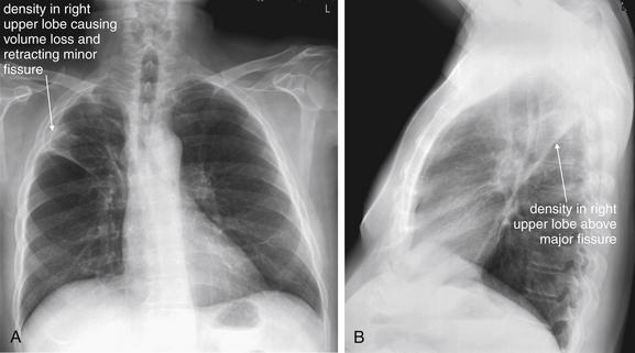
A, Posterior-anterior (PA) chest x-ray. B, Lateral chest x-ray. This 59-year-old male with stage IIIB non–small cell lung cancer presented with an episode of hemoptysis during which he expectorated approximately 1⁄2 mL of blood mixed with sputum. On the posterior–anterior view, the patient’s mass is present just above the minor fissure and has caused volume loss in the right upper lobe. Retraction of the right upper lobe like an accordion has pulled the minor fissure cephalad (remember, the minor fissure should be a thin horizontal line on the frontal chest x-ray). On the lateral view, the mass extends to the major fissure. Although technically an upper lobe pneumonia could be associated with mucous plugging and atelectasis with volume loss, these findings should suggest an associated mass. If the clinical history suggests pneumonia, with fever, cough, and sputum production, treat for possible postobstructive pneumonia—but arrange follow-up imaging to evaluate for an underlying mass. See additional chest x-rays from this patient, Figures 5-164 and 5-165.
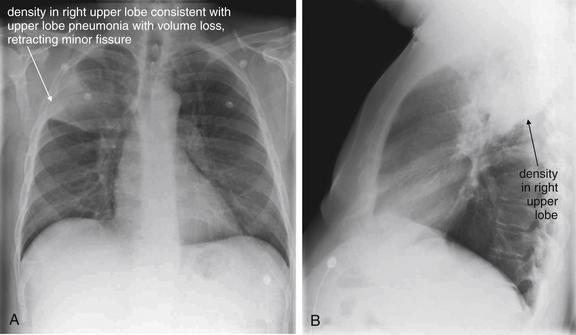
Figure 5-164 Lung mass presenting with hemoptysis.
Same patient as Figure 5-163. A, Posterior-anterior (PA) chest x-ray. B, Lateral chest x-ray. This chest x-ray preceded his cancer diagnosis. On this occasion, he presented with chest pain and was diagnosed with a right upper lobe pneumonia. Note the volume loss, indicated by elevation of the minor fissure on the posterior–anterior view. On the lateral view, the density is bounded inferiorly by the major fissure. The radiologist diagnosed right upper lobe pneumonia but appropriately recommended “radiographic follow-up to complete resolution.” The lesion failed to resolve completely, leading to the diagnosis of lung cancer.
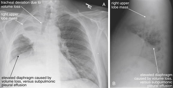
Same patient as Figures 5-163 and 5-164. A, Posterior-anterior (PA) chest x-ray. B, Lateral chest x-ray. Two years later, the patient has progression of his cancer and has continued chest pain. The lesion has caused more volume loss in the right upper lobe. Not only is the minor fissure pulled cephalad, but the trachea is also deviated to the right. The right diaphragm is now elevated as well because of right lung volume loss. A subpulmonic effusion is also possible.
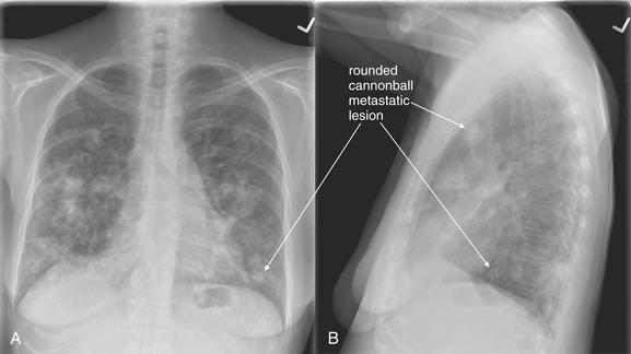
Figure 5-166 Metastatic disease with cannonball emboli.
A, Posterior-anterior (PA) chest x-ray. B, Lateral chest x-ray. Any neoplasm with hematogenous spread to lung can form so-called cannonball emboli. These are small tumor emboli that shower the lungs, implant, and then grow in situ. The characteristic appearance is of scattered, rounded, bilateral lung opacities. Septic emboli from endocarditis could have a similar appearance. The primary neoplasm cannot be determined from the radiographic appearance. As these lesions grow, they can become confluent and lose their rounded shape. This 66-year-old female with metastatic non–small cell lung cancer and rectal carcinoma presented with right upper back pain and upper extremity paresthesias. Review her CT images in Figure 5-167.
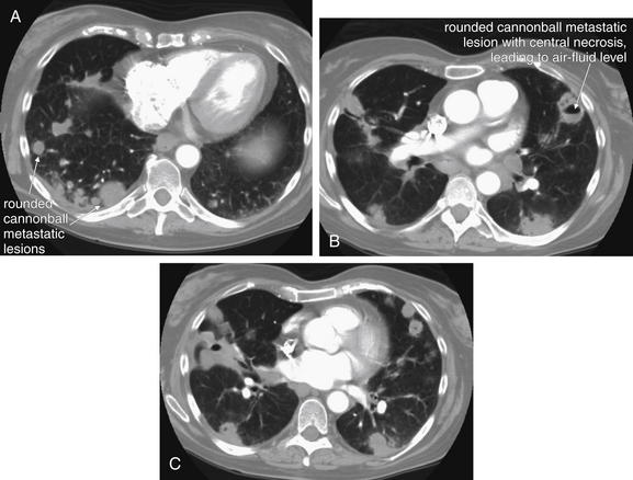
Figure 5-167 Metastatic disease with cannonball emboli.
Same patient as Figure 5-166. CT with IV contrast, viewed on lung windows. A, B, and C are axial slices at various levels through the chest, depicting the extent of metastatic disease. Some of the lesions have undergone central necrosis and have air–fluid levels (remember, air is black on lung windows). Septic emboli from endocarditis could result in small lung abscesses with an identical appearance.
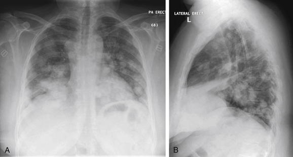
Figure 5-168 Metastatic disease with cannonball emboli.
A, Posterior-anterior (PA) chest x-ray. B, Lateral chest x-ray. This 46-year-old female with metastatic cervical cancer presented with lower extremity weakness and gait difficulty. Her x-ray shows the same pattern of scattered, rounded, bilateral, fluffy densities as in the previous patient, a hallmark of metastatic tumor emboli.
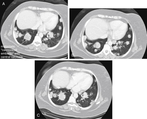
Figure 5-169 Metastatic disease with cannonball emboli.
Same patient as Figure 5-168. The patient’s chest CT with IV contrast shows numerous rounded lung densities consistent with diffuse metastatic disease. Some have lower density centers (darker gray on lung windows), consistent with central necrosis. A, B, and C, axial slices at various levels through the chest depicting the extent of metastatic disease, viewed on lung windows.
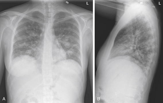
Figure 5-170 Metastatic disease with cannonball emboli.
A, Posterior-anterior (PA) chest x-ray. B, Lateral chest x-ray. This 27-year-old female with metastatic pancreatic cancer presented with fever. Her fever workup included a chest x-ray that shows metastatic disease in the same pattern as the previous figures, with multiple scattered, rounded, bilateral lung densities.
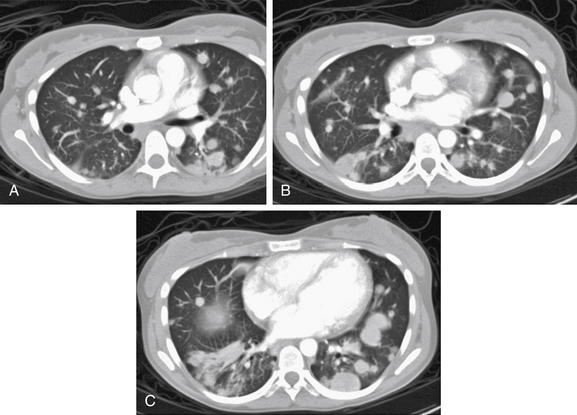
Figure 5-171 Metastatic disease with cannonball emboli.
Same patient as Figure 5-170. The patient’s chest CT with IV contrast shows the same pattern of scattered bilateral rounded lung lesions, characteristic of metastatic tumor emboli. Tiny emboli shower the lungs, implant, and grow. Some have lower-density centers, suggesting central necrosis. The rounded appearance occurs from concentric growth of a clone of tumor cells. A-C, Axial slices viewed on lung windows, progressing from cephalad to caudad.
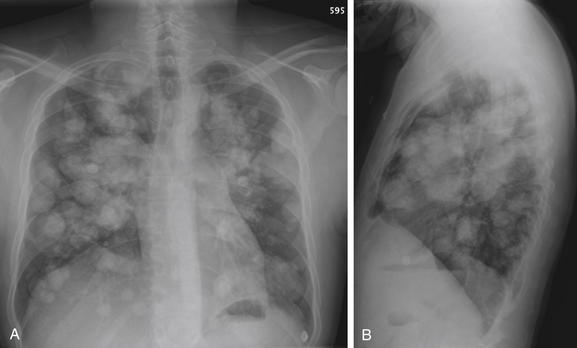
Figure 5-172 Metastatic disease with cannonball emboli.
A, Posterior-anterior (PA) chest x-ray. B, Lateral chest x-ray. This patient with metastatic osteosarcoma has the classic appearance of pulmonary metastatic disease, with innumerable rounded, bilateral nodules. These occur as tumor cells are carried hematogenously to the lungs, implant, and grow. Nodules of different sizes may have seeded at different times.
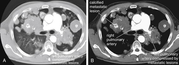
Figure 5-173 Metastatic disease with cannonball emboli.
Same patient as Figure 5-172. A, Chest CT with IV contrast, axial image viewed on lung windows. B, Same image viewed on soft-tissue windows. Here, confluent metastatic lesions are creating a unique problem: the left pulmonary artery is surrounded and compressed. Compare the diameter of the right and left pulmonary arteries. Consider if this patient were to undergo a ventilation–perfusion (VQ) scan for suspected pulmonary embolism. Extrinsic compression of a pulmonary artery can create VQ mismatch, resulting in a false-positive result for thrombotic pulmonary embolism. Another feature of these lesions is internal calcifications, although a noncontrast computed tomography would demonstrate this more clearly. The white markings within the lesions are calcium deposits, not injected contrast material.
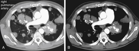
Figure 5-174 Metastatic disease with cannonball emboli.
Same patient as Figure 5-172 and 5-173. The right pulmonary artery remains patent despite encroaching metastatic lesions. A, Chest CT with IV contrast, axial image viewed on lung windows. B, Same image viewed on soft-tissue windows.
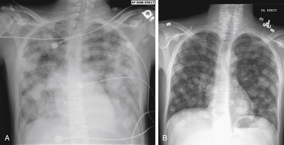
Figure 5-175 Metastatic disease with cannonball emboli: Testicular cancer.
Previously healthy 22-year-old male presenting in respiratory distress. A, Anterior-posterior (AP) chest x-ray showed diffuse cannonball emboli. These are so extensive that they are becoming confluent. On examination, he was noted to have a previously undiagnosed testicular mass. B, Posterior-anterior (PA) chest x-ray obtained months later, the patient has shown a response to chemotherapy, albeit incomplete.
Mediastinal Masses and Adenopathy
Mediastinal masses and adenopathy may widen the mediastinum on the frontal projection (Figures 5-176 through 5-178). On the lateral projection, the retrosternal space may be opacified, indicating a mass lesion (see Box 5-3) (Figures 5-179 through 5-182). Hilar adenopathy may be seen with malignancies, infections, and conditions such as sarcoidosis (Figures 5-183 and 5-184). CT scan may be necessary to distinguish a possible mediastinal mass from conditions as benign as hiatal hernia (Figures 5-185 and 5-186) or as life threatening as aortic aneurysm (discussed in detail in Chapter 7). Mediastinal masses can result in superior vena cava syndrome (see Figures 5-179 through 5-182). Chest x-ray may detect the mass but does not evaluate compression or internal thrombosis of the superior vena cava, which is best assessed with CT with IV contrast.
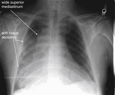
Figure 5-176 Wide mediastinum.
This 64-year-old male presented with interscapular back pain, chest pain, and neck pain. Chest x-ray shows a wide mediastinum with an indistinct right heart border and medial right diaphragm, corresponding to possible infiltrates in the right middle and lower lobes. Is this a pleural effusion? The right costophrenic angle is not blunted. What is your interpretation? Compare this with the posterior–anterior and lateral chest x-ray in Figure 5-177 and the CT in Figure 5-178.
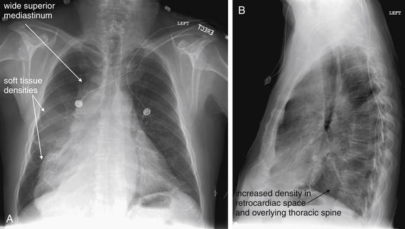
Figure 5-177 Wide mediastinum.
Same patient as Figure 5-176. A, Posterior-anterior (PA) chest x-ray. B, Lateral chest x-ray. The PA chest x-ray shows a bizarre mediastinal contour, wide at the top and even more so near the diaphragm. Without other clinical information, an appropriate interpretation could be densities overlying the right heart border and right medial diaphragm, corresponding to the right middle and lower lobes. On the lateral view, the retrocardiac space appears dense, without the normal increase in lucency of the thoracic spine approaching the diaphragm (the spine sign). Computed tomography was performed for evaluation of the aorta and mediastinum (Figure 5-178).
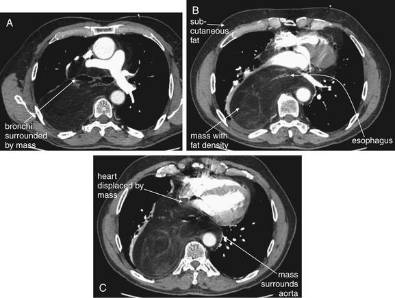
Figure 5-178 Liposarcoma of mediastinum.
Same patient as Figures 5-176 and 5-177. His chest x-ray showed a wide mediastinum. A-C, Chest CT with IV contrast, axial images viewed on soft-tissue windows. A through C progress from cephalad to caudad. His CT showed a normal aorta—a wide mediastinum is not synonymous with aortic pathology. Instead, a large mediastinal mass surrounding the aorta was found. This mass is fat density—compare with subcutaneous fat on the same images. The mass surrounds the esophagus and displaces the heart anteriorly. It also surrounds the trachea and esophagus and displaces the main bronchi. Look back at the chest x-rays in the prior two figures. The mediastinal silhouette is more understandable with the CT findings in mind.
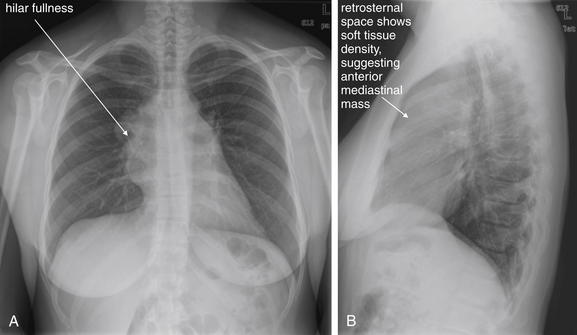
Figure 5-179 Mediastinal mass with superior vena cava syndrome.
A, Posterior-anterior (PA) chest x-ray. B, Lateral chest x-ray. This 39-year-old healthy female presented with 1 week of bilateral neck pain, shortness of breath, and lightheadedness. She also noted enlarging neck veins a few days prior. Her chest x-ray shows prominence in both hila on the posterior–anterior view. The lateral view shows soft-tissue density in the retrosternal space anterior to the heart—suspicious for an anterior mediastinal mass. Compare this with Figures 5-16 and 5-17, which show both normal and abnormal retrosternal spaces. Also compare with Figure 5-183, where hilar masses are present on the frontal projection, but the lateral x-ray shows a clear retrosternal space. The clinical presentation suggests either superior vena cava syndrome or a pericardial effusion. The heart size is normal on this chest x-ray, and the other findings suggest an anterior mediastinal mass with superior vena cava syndrome. Chest CT from the patient is shown in Figure 5-180.
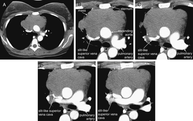
Figure 5-180 Mediastinal mass with superior vena cava (SVC) syndrome because of extrinsic compression.
As suggested by the chest x-ray in Figure 5-179, this patient has an anterior mediastinal mass. Chest CT with IV contrast, viewed on soft-tissue windows. A, A single complete axial slice is shown for context. The remaining slices have been cropped to focus on the mass and great vessels. B through E progress from cephalad to caudad. Between the sternum and the ascending aorta lies a large soft-tissue mass. This is extrinsically compressing the SVC to a slit, explaining the patient’s dilated neck veins. Compare with the next case, which shows internal thrombosis of the SVC, also causing SVC syndrome. Biopsy here confirmed diffuse large B cell lymphoma, primary mediastinal.
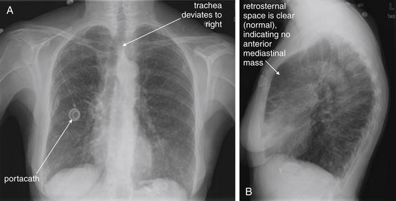
Figure 5-181 Superior vena cava (SVC) syndrome.
A, Posterior-anterior (PA) chest x-ray. B, Lateral chest x-ray. This 75-year-old female with Mycobacterium avium and subsequent bronchiectasis presented with 2 days of increasing swelling in the face and dilatation of her neck veins. The presentation suggests SVC syndrome or large pericardial effusion impairing venous return to the chest. However, on her chest x-ray, the heart size appears normal and the mediastinum appears normal in size, making mediastinal mass less likely. The trachea does appear deviated on the posterior–anterior view, which can be a sign of a mediastinal mass. On the lateral view, the retrosternal space is clear, making anterior mediastinal mass unlikely. The patient has a portacath in the right chest. A chest CT was performed to assess further (Figure 5-182).
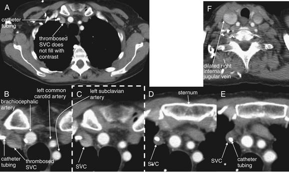
Figure 5-182 Superior vena cava (SVC) syndrome from internal thrombosis of the SVC.
Same patient as in Figure 5-181. Chest CT with IV contrast, viewed on soft-tissue windows. A, Single full axial slice is shown for context. C, The image outlined in a dashed line is a cropped view from the full slice (A). The other views are cropped and enlarged to focus on the great vessels. B through E progress from cephalad to caudad. Her CT shows thrombosis of the SVC at the point at which her portacath tubing enters from the right subclavian vein—note the absence of contrast within the SVC. The portacath tubing is visible as a bright white circle, surrounded by thrombus. F, Cephalad to the entry of the catheter, the internal jugular veins are patent and contrast filled—in fact, dilated because of the obstructed SVC. Not shown, the SVC becomes visible again below the level of thrombosis and is filled with contrast. Compare this case with the prior case of SVC syndrome from extrinsic compression (Figures 5-179 and 5-180).
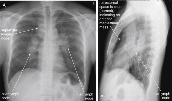
Figure 5-183 Lymphoma versus sarcoidosis.
A, Posterior-anterior (PA) chest x-ray. B, Lateral chest x-ray. This 31-year-old male presented with hematuria, suprapubic abdominal pain, nausea and vomiting, and nonproductive cough. Chest x-ray showed bilateral hilar and suprahilar lymph nodes. On the posterior–anterior and lateral views, these are seen as densities outlining the trachea and main bronchi. The anterior mediastinum does not appear to be involved, as a normal lucency persists anterior to the heart on the lateral x-ray. The differential diagnosis includes sarcoidosis and lymphoma. Computed tomography was performed (Figure 5-184). The patient’s workup was consistent with sarcoidosis.
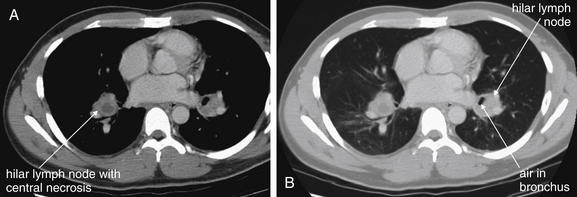
Figure 5-184 Lymphoma versus sarcoidosis.
Same patient as Figure 5-183, where chest x-ray shows bilateral hilar lymphadenopathy. A, Soft-tissue windows. B, Lung windows. The patient’s chest CT without IV contrast shows soft-tissue densities consistent with lymph nodes near both hila. The right lymph node has a central area of decreased (fluid) density, consistent with necrosis. The air collection adjacent to the left lymph node can be tracked through adjacent CT slices and is actually a branch of the left main bronchus, not an air–fluid level in the lymph node. Importantly, no other mediastinal nodes are seen, and the remainder of the patient’s CT of the chest and abdomen was negative for other adenopathy. His workup was consistent with sarcoidosis, not lymphoma.
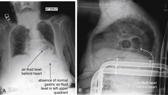
A, Anterior-posterior (AP) chest x-ray. B, Lateral chest x-ray. This 82-year-old female with chronic obstructive pulmonary disease presented with 10 days of cough and dyspnea. Her heart rate was 129 with a temperature of 38.2°C and an oxygen saturation of 92% on room air. Her chest x-ray shows an air–fluid level overlying the heart on the anterior–posterior view and behind the heart on the lateral view. The patient is severely kyphotic. Consider the normal mediastinal anatomy. The esophagus lies in the posterior mediastinum behind the heart and anterior to the aorta. Note the absence of a gastric air bubble in the left upper quadrant. The mass with the air–fluid level in this case is a hiatal hernia. CT was performed to rule out a pulmonary abscess, given the patient’s fever and respiratory symptoms (Figure 5-186). A gastric volvulus could have a similar appearance and could be evaluated with barium swallow.
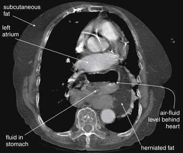
CT with IV contrast, viewed on soft-tissue windows. Compare with the chest x-ray from the same patient in Figure 5-185. This image is taken at the level of the left atrium, which lies just anterior to the air- and fluid-containing structure—a hiatal hernia. Just left of the stomach is herniated fat (compare with subcutaneous fat).
Esophageal and Tracheal Foreign Bodies
Esophageal and tracheal foreign bodies are a common emergency department complaint, particularly in children. Dense foreign bodies composed of metal may be readily seen on chest x-ray. Other foreign bodies may be radiolucent and invisible on x-ray. In some cases, the presence of a foreign body may be deduced by its effect on lung inflation. An airway foreign body causing a ball–valve effect may cause unilateral hyperinflation, sometimes most visible on expiratory or lateral decubitus views (described earlier in dedicated sections on those specialized views). CT scan is accurate and can localize even low-density objects.
Esophageal foreign bodies often lodge at the thoracic inlet. If an esophageal foreign body is suspected but is not visible by chest x-ray, a barium swallow can be performed and can outline a nonradiopaque esophageal foreign body.
Tracheal foreign bodies may lodge at multiple levels depending on object size relative to the patient’s airway. Coins are a commonly aspirated or ingested foreign body. Classically, a coin appears en face as an “O” on the frontal view when lodged in the esophagus (Figure 5-187). A mnemonic for this is the British spelling, oesophagus. A coin in the trachea typically is turned “edge on” and appears as a linear opacity on the frontal chest x-ray, coaxed into this position by the incomplete tracheal cartilages, which are open posteriorly.
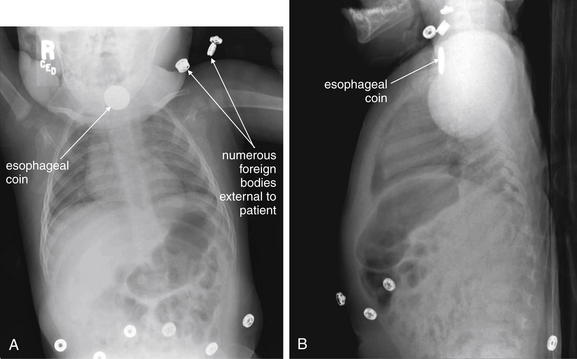
Figure 5-187 Esophageal foreign bodies (coin).
A, Frontal projection chest x-ray. B, Lateral chest x-ray. This 11-month-old child developed cough and irregular breathing and was thought to have ingested a foreign body. Chest x-ray shows a disc-shaped object with the classic appearance of an esophageal coin. This had the dimensions of a nickel and was removed with a coin forceps under general anesthesia. Typically, coins in the esophagus orient themselves en face in the frontal plane so that they appear circular like an “O” on frontal chest x-ray (think of the British spelling oesophagus). Naturally, they appear linear on lateral x-ray. Tracheal coins tend to orient themselves in a midsagittal plane, apparently because of the incomplete cartilaginous tracheal rings, which are open posteriorly. Remember also the risk of esophageal perforation from an ingested watch battery, which can have a similar appearance to coins. An example is shown in the abdominal imaging chapter (Chapter 9). Learn one more lesson from the images here: when searching for an ingested foreign body, undress the patient and remove any unnecessary external radiopaque foreign bodies to avoid confusion.
Chest X-ray Findings of Traumatic Injury
Chest x-ray and adjunctive imaging evaluation of traumatic injury is discussed in detail in Chapter 6. Please see Chapter 6 for a discussion of pneumothorax, pulmonary contusion, diaphragm rupture (also discussed in Chapter 10), rib and sternal fractures, and aortic injury.
Chest X-ray Evaluation of Medical Devices
Chest x-ray is commonly used to evaluate the location of medical devices within the chest, as well as complications of their insertion. Endotracheal tubes, nasogastric and orogastric tubes, central venous catheters, and thoracostomy tubes are discussed in detail in Chapter 6. Please see the description of their assessment in that chapter. The discussion here supplements but does not replace the discourse in Chapter 6.
Endotracheal Tubes
Chest x-ray is commonly obtained following endotracheal intubation to assess endotracheal tube position. It is essential to recognize that chest x-ray assesses the depth of endotracheal tube insertion, not correct tracheal placement. Because the esophagus lies deep to the trachea and both are midline structures, a frontal projection chest x-ray cannot distinguish tracheal from esophageal intubation. Other factors, including direct visualization of the endotracheal tube passing through the vocal cords during intubation, the presence of appropriate end-tidal carbon dioxide production, oxygen saturation, the presence of bilateral breath sounds, and the absence of gastric air sounds during ventilation, should be used in conjunction with the chest x-ray. Chest x-ray alone should never be used to confirm correct endotracheal positioning.
On chest x-ray, the distal tip of the endotracheal tube should be positioned no deeper than approximately 1 to 3 cm above the carina and no higher than the suprasternal notch. Deeper insertion may lead to right main bronchus intubation if the patient’s neck becomes flexed or if the tube is advanced farther. Insertion to a depth shallower than the suprasternal notch risks accidental extubation (withdrawal of the endotracheal tube to a supraglottic position) if the patient’s neck is extended or if the tube is retracted farther.
Right main bronchus intubation (see Figure 5-39) is a common complication of endotracheal intubation and should be routinely suspected and assessed for on chest x-ray. Clinical assessment should also be performed for decreased breath sounds on the patient’s left side. If not corrected rapidly, right main bronchus intubation can be followed by complete collapse of the left lung. Chest x-ray findings include volume loss in the left chest, with tracheal and mediastinal shift to the left (see the section earlier in this chapter on volume loss). This is usually rapidly corrected with appropriate repositioning of the endotracheal tube. Sometimes right main bronchus intubation occludes large branches of the right bronchus, with segmental collapse, most often of the right upper lobe.
Central Venous Catheters
Chest x-ray can detect misplaced central venous catheters whose course does not follow the intended vascular anatomy (Figure 5-188). For example, a catheter inserted into the subclavian vein may be found to ascend the neck, suggesting an improper course into the internal jugular vein rather than descent into the superior vena cava. An internal jugular catheter may turn laterally toward the shoulder, rather than medially, suggesting accidental subclavian vein placement. It is essential to recognize that even these findings do not rule out the more serious complication, arterial catheterization. A catheter placed into the carotid artery and advanced into the subclavian artery would have a similar chest x-ray appearance. Though it is commonly requested that a chest x-ray be performed before the use of a central venous catheter to confirm correct placement, chest x-ray does not confirm intravenous insertion. Other factors, including the absence of pulsatile blood suggesting arterial placement, the ease of infusion through the catheter, and ultrasound assessment of the catheter position, can be used with chest x-ray to assess catheter location. In cases of particular uncertainty, blood gas sampling or transduction of central venous pressure waveforms may be useful. The major functions of the chest x-ray are to determine the depth of insertion of the catheter and to evaluate for pneumothorax. A central venous catheter should terminate in the lower superior vena cava, above the right atrium.
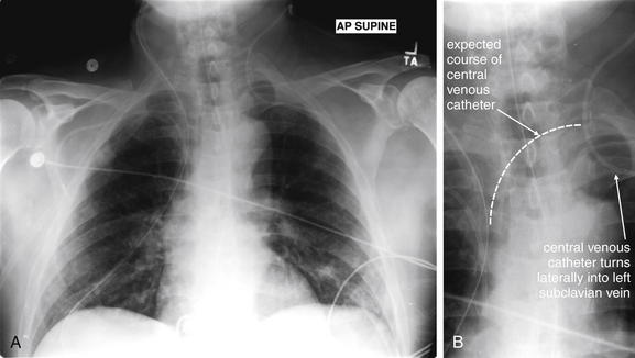
Figure 5-188 Misplaced central venous catheter.
Chest x-rays are routinely obtained to assess the position of medical devices such as central venous catheters and to identify complications such as pneumothorax. Routine parts of the process of image review should be to locate foreign bodies, assess their identity, and determine whether they are correctly positioned. This patient has multiple foreign bodies visible. The left internal jugular catheter does not take the expected course toward the superior vena cava on the patient’s right. Instead, it turns laterally into the left subclavian vein. A, Anterior-posterior (AP) supine chest x-ray. B, Close-up from A.
Thoracostomy and gastric tubes are discussed in Chapter 6. An improperly placed gastric tube may be seen coiled in the hypopharynx or esophagus on chest x-ray. More subtle but critical misplacement in the trachea and bronchus may be seen as a gastric tube that deviates right or left from the midline at the level of the carina (Figure 5-189). Failure to recognize this can be fatal, if lavage fluids or feeding solutions are passed into the lung through the misplaced gastric tube.
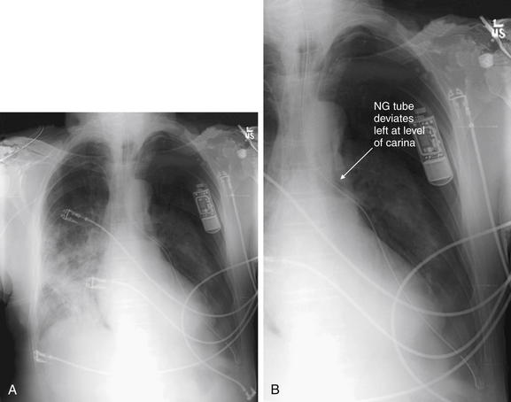
Figure 5-189 Misplaced nasogastric tube.
Always assess the chest x-ray image for foreign bodies and attempt to determine their locations. In this patient, a nasogastric tube has been placed. The tube unexpectedly leaves the midline and courses through the left chest before terminating as expected in the left upper quadrant of the abdomen. This unusual path makes it unlikely that the tube is within the esophagus, which is usually a midline structure until it crosses the diaphragm and reaches the stomach. Instead, the nasogastric tube appears to diverge left at the level of the carina—meaning that it has been erroneously placed into the trachea and then the left main bronchus. Had the patient been fed or received lavage through this tube, the results could have been disastrous. A, Frontal projection chest x-ray. B, Close-up from A.
Automatic Implantable Cardioverter–Defibrillators and Implanted Pacemakers
Chest x-ray can be used to evaluate the integrity of automatic implantable cardioverter–defibrillator (AICD) and pacemaker electrical leads (Figures 5-190 through 5-192). The leads should be visible originating from the pacemaker or AICD, tracking in a path corresponding to great veins returning to the superior vena cava and then to the right atria and right ventricle. The correct position of the leads depends on the specific device; for example, some devices pace both ventricles. The wires should not be kinked, have discontinuities, or terminate in a location outside the atria or ventricles. Rarely, patients with Twiddler’s syndrome may be found to have wound the electrical leads completely around the pacemaker or AICD by rotating the device inside its subcutaneous pocket.28
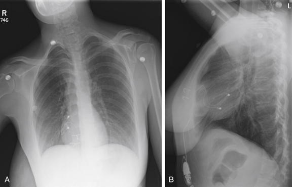
Figure 5-190 Pacemaker wire not attached.
A, Frontal projection chest x-ray. B, Lateral chest x-ray. This 25-year-old female recently underwent thoracic pacemaker replacement with an abdominal pacemaker because of local site irritation. She presented with lightheadedness. The inferior epicardial pacemaker wire does not connect to the pacemaker (see the close-up in Figure 5-191). When a pacemaker problem is suspected, always inspect the course of the wires for kinks or discontinuities.
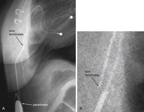
Figure 5-191 Pacemaker wire not attached.
Same patient as in Figure 5-190. A, Close-up from lateral chest x-ray. B, A very enlarged view from A with the contrast and brightness adjusted to visualize the disconnected pacemaker wire.
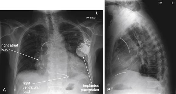
A, Posterior-anterior (PA) chest x-ray. B, Lateral chest x-ray. This 58-year-old male with a history of coronary artery disease, heart failure, and renal insufficiency presented with increasing dyspnea and edema to the lower abdomen. His chest x-ray shows the normal configuration of an implanted pacemaker with right atrial and ventricular leads. The wires connect to the pacemaker appropriately and show no kinks or breaks. The tips are in the expected positions overlying the right atrium and ventricle. An electrocardiogram and pulse examination are needed to assess whether the pacemaker is firing appropriately and achieving capture.
Transvenous Pacemakers
Transvenous pacemakers placed in the emergency department should be assessed after placement using chest x-ray (Figures 5-193 through 5-197). Chest x-ray in this scenario performs several functions. First, it assesses for pneumothorax resulting from the insertion of the vascular catheter through which the pacemaker electrodes have been introduced. Second, it assesses the depth of insertion of the pacemaker electrode. Typically, this is a single electrical wire, terminating in the right ventricle to allow ventricular pacing. Ideally, the electrode should not be coiled or kinked. If extra loops of wire are present in the atria or ventricle, they may become a nidus for thrombus formation and may also induce premature ventricular contractions or other dysrhythmias from mechanical irritation of the ventricle. In some cases, the electrode may be found to have passed from the superior vena cava, through the right atrium, and into the inferior vena cava, rather than entering the right ventricle. Typically, this scenario would have been suspected from the failure of the transvenous pacemaker to achieve electrical capture of the ventricle. Although chest x-ray is important to assess for complications of the procedure, remember that the function of the transvenous pacemaker is more important than cosmetic considerations on chest x-ray. Resist the urge to reposition a coiled but functioning pacemaker electrode until the patient has been stabilized. Repositioning a coiled electrode may disturb the contact of the electrode with the ventricle and could result in failure to capture.
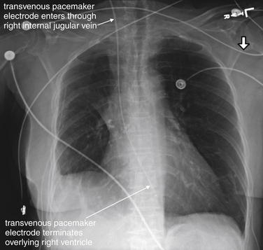
Figure 5-193 Transvenous pacemaker wire.
Frontal projection chest x-ray. This 77-year-old female, recently discharged after admission for rapid atrial flutter, had increased her calcium channel and beta-blocker doses. Today, her husband noted the patient felt “sick.” Emergency medical services found the patient to be diaphoretic, hypotensive, and bradycardic. In the emergency department, the patient had an unmeasurable blood pressure with a heart rate of 35. Her electrocardiogram showed atrial flutter with third-degree heart block and a junctional escape rhythm. She did not respond to medications and a transvenous pacemaker was placed by a right internal jugular vein approach by an emergency physician using ultrasound guidance. Note the relatively straight course of the catheter from this entry point, which makes this the preferred approach. Physical examination for pulses and electrocardiogram are needed to confirm that the pacemaker is achieving capture.
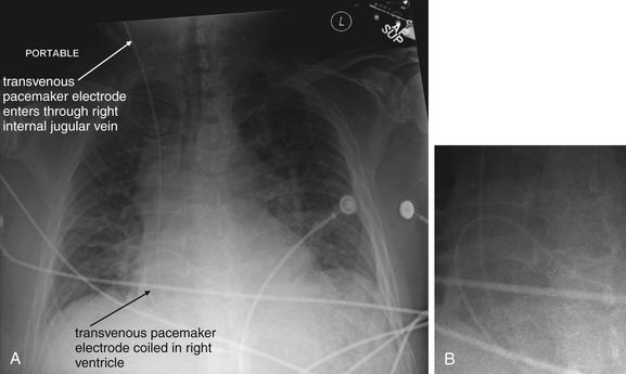
Figure 5-194 Transvenous pacemaker wire.
This 58-year-old male with a history of paroxysmal atrial fibrillation and sick sinus syndrome underwent an atrioventricular nodal ablation 2 days earlier. He presented with syncope and was unable to stand. His electrocardiogram showed no P waves and a junctional rhythm. No blood pressure could be obtained, and the patient remained lightheaded, bradycardic, and dyspneic despite medications. A transvenous pacemaker was placed by a right internal jugular vein approach. The electrode is coiled in a position overlying the right ventricle. Despite this, it achieved capture and the patient was stabilized. Notice the heterogeneous opacities consistent with pulmonary edema—this patient was in cardiogenic shock because of his bradycardia. A, Anterior-posterior (AP) supine chest x-ray. B, Close-up from A to demonstrate the coiled electrode.
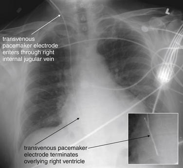
Figure 5-195 Transvenous pacemaker wire.
Same patient as Figure 5-194. The pacing electrode has been repositioned and is no longer coiled. The patient’s lung fields appear clearer than in the previous x-ray, indicating resolution of his pulmonary edema now that his pacemaker is functioning and his heart rate is appropriate. Small panel is an enlarged view from the AP chest x-ray, with contrast adjusted to accentuate the pacemaker wire.
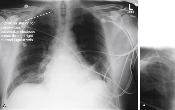
Figure 5-196 Transvenous pacemaker wire.
Same patient as Figure 5-195, the following day. The pacemaker has been removed, as the patient had returned to normal sinus rhythm. The introducer catheter is still present through the right internal jugular vein. A, Anterior-posterior (AP) chest x-ray. B, Close-up from A, focused on the internal jugular catheter.
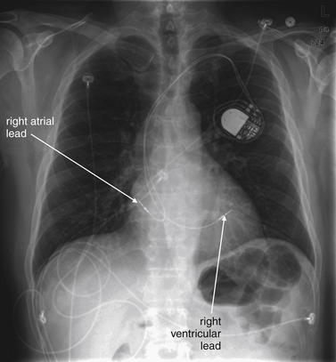
Figure 5-197 Permanent implanted pacemaker.
Same patient as Figures 5-194 through 5-196. The patient presented again with syncope and bradycardia. A permanent pacemaker was placed with right atrial and ventricular leads.
Structured and Systematic Approach to Chest X-ray Image Interpretation
Now that we’ve reviewed basic principles of chest x-ray imaging, and features of pathologic conditions, we are ready to interpret the chest x-ray in a systematic fashion (Tables 5-8 and 5-9).
TABLE 5-8 Assessment of a Chest X-ray Technique in Preparation for Interpretation
| Action | Error Prevented |
|---|---|
| Lower the room lights | Improves contrast resolution, making low-contrast lesions more visible. |
| Confirm that the image belongs to the patient in question | Prevents “wrong patient” error. |
| Confirm that the date of the image being viewed corresponds to the current or desired date | Prevents erroneous action based on previous radiograph. |
| Note the exam technique (e.g., PA, AP, supine, upright, or lordotic) | Reminds the physician of diagnostic limitations and artifacts associated with specific x-ray techniques. |
| Assess for lordotic positioning | May cause asymmetrical magnification of mediastinum and heart. |
| Confirm right–left orientation | Prevents “wrong site” error. |
| Assess for patient rotation | Prevents false appearance of mediastinal widening, mediastinal shift, or tracheal deviation due to rotation. |
| Assess adequacy of lung expansion–inspiratory effort | Checks for poor inspiratory effort, which can simulate pulmonary edema. |
| Assess chest x-ray exposure | Checks for underexposure, which can simulate pulmonary edema, and overexposure, which can hide lung field details such as pneumothorax. |
| Compare the current exam with previous images from the same patient | May reveal an abnormality on the current examination to be unchanged from prior examinations and therefore not the likely cause of current acute symptoms. Unnecessary diagnostic testing and therapeutic interventions may be prevented by such a comparison. In other cases, a subtle abnormality on the current exam may prove to be new compared with prior images and thus cause for concern, with further diagnostic testing or treatments being indicated. |
Whenever possible, view the chest x-ray using low ambient light conditions. Radiologists have the benefit of dark-adapting for long periods and viewing x-rays under low-light conditions. Emergency physicians more often view x-rays in fully lit rooms or immediately after dimming the room lights, compromising the eye’s ability to adapt optimally. Nonetheless, using low light conditions can improve your ability to recognize subtle findings.
Assessing Chest X-ray Image Quality and Technique
Before beginning a systematic search of the chest x-ray image, look at the image as a whole to gain a general sense of the patient’s anatomy and positioning. Consider the patient’s age and gender, as these create a context and differential diagnosis for any imaging findings. This step is particularly important for a radiologist, who generally has not met or examined the patient. For the emergency physician, this step has generally occurred already during the history and physical examination, but taking a moment to refocus on these questions can be valuable.
Follow these basic steps to avoid errors in diagnosis (see Table 5-8). First, confirm that the image belongs to the patient in question. Second, confirm that the date of the image being viewed corresponds to the current or the desired date. Third, note the examination technique (e.g., PA or AP and supine or upright). As you have already discovered, a PA image gives a more accurate and less magnified view of the heart, so understanding which type of image you are viewing will help you to accurately assess heart size and mediastinal width. As discussed earlier, a supine film may not display air–fluid levels and may be less sensitive for detection of subdiaphragmatic air, so the patient’s position at the time of the examination is important to assess. Assess for lordotic versus fully upright positioning. Lordotic positioning (positioning of the patient in only a semiupright position, with the upper thorax leaning backward) results in more horizontal appearance of the upper ribs compared with the fully upright technique.
Next, confirm left and right orientation (Figure 5-198). The conventional orientation of the image is with the patient’s right side displayed on the left side of the screen or printed image, as if the examiner is facing the patient. The patient’s position and left–right orientation are usually identified by radiopaque markers placed on the x-ray detector at the time of image acquisition. Although left–right orientation may appear obvious because of the usual orientation of the heart within the chest, rare cases of dextrocardia may occur. In these cases, without skin markers to indicate orientation, the image might be falsely assumed to be reversed, potentially leading to patient injury—for example, by erroneous placement of a thoracostomy tube on the wrong side of the patient. A more common human error may occur; an image may be loaded incorrectly into the digital radiography system, and erroneous labeling of the image is probably more likely than dextrocardia. Nonetheless, leave nothing to chance if questions exist about the patient’s anatomy. If necessary, repeat a chest x-ray to confirm the heart’s position.
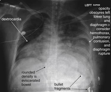
Figure 5-198 Situs inversus or dextrocardia with gunshot wound.
This 34-year-old male presented with gunshot wounds to the left upper abdomen and lower chest. On examination, small bowel was noted to be protruding from center of the anterior chest. Clearly, the patient requires operative exploration, and imaging plays a limited role. However, chest x-ray in this case shows several important findings. The heart lies completely in the right chest. From this x-ray, it is not clear if this is isolated dextrocardia or situs inversus. In the operating room, the patient was found to have situs inversus with left upper quadrant liver injury from the gunshot wound. The left diaphragm is obscured on this chest x-ray. As we discussed earlier, in the supine position this may indicate pleural fluid (hemothorax), pulmonary contusion, or diaphragm injury with herniation of abdominal contents into the chest. If a chest tube is placed, special care must be taken to avoid injury to any herniated abdominal contents. The eviscerated bowel is visible as a density in the central abdomen. Bullet fragments are also seen. No pneumothorax was visible, although a chest tube was placed because of obvious concern for this.
Next, assess patient rotation. Rotation can create artifacts, such as apparent tracheal deviation or mediastinal shift. In addition, rotation of the patient artifactually widens the mediastinum, simulating pathology. Occasionally, rotation (an oblique view of the chest) is intentionally used for diagnostic purposes, but this is rarely done in the emergency department. Rotation may be assessed by examining the position of the medial heads of the clavicles relative to one another. If the patient is rotated, the more anterior clavicle will appear medially displaced (see Figure 5-21). To simulate this effect, sit in a swiveling chair and place your fingertips on your sternoclavicular joints. Sit facing fully forward, and then rotate right and left. Imagine the change in the position of your clavicular heads if a chest x-ray were performed with you in these positions. In addition to shifting the position of the clavicular heads, the distance between the clavicular heads appears to narrow with an increasing degree of rotation from a true frontal position. The apparent width of the mediastinum may also change with this adjustment in position.
Assess the adequacy of lung expansion–inspiratory effort, as this can affect the apparent density of lung tissues and the size of pneumothoraces, as described earlier. Ideally, the patient should have 10 visible ribs above the diaphragm.
As described earlier, the chest x-ray exposure should be assessed. An overexposed film appears excessively black, as the detector or x-ray film has been fully exposed by excess radiation. An overexposed film loses most soft-tissue detail, but bony structures may be preserved, as these dense objects prevent through transmission of some radiation. An underexposed film appears excessively white, as not enough radiation has been applied to the patient to be transmitted through to the detector or film to change the color from white to black. Modern PACS displays allow adjustment of brightness and contrast, to some degree alleviating these issues, but no amount of adjustment of brightness and contrast can eliminate problems from substantial overexposure or underexposure.
A final key step in interpretation of chest x-rays and other diagnostic imaging is to compare the current examination with previous images from the same patient. In some cases, a glaring abnormality on the current examination may be found to be unchanged or even improved from prior examinations and therefore not the likely cause of current acute symptoms. Unnecessary diagnostic testing and therapeutic interventions may be prevented by such comparison. In other cases, a subtle abnormality on the current examination may prove to be new compared with prior images and thus cause for concern, with further diagnostic testing or treatments being indicated.
Systematic Search of the Chest X-ray
After assessing the chest x-ray image, conduct a systematic search of all regions of the image, rather than gazing at the image center and relying on peripheral vision to reveal abnormalities. Because the maximum image resolution is obtained by centering an image on the fovea of your eye, centering your vision on each region of the chest x-ray in turn is necessary, in addition to taking an overall view of the image.
Many algorithms have been proposed for the systematic review of the chest x-ray. All share a common feature: they force the reader to analyze all major elements of the image comprehensively, rather than allowing an unstructured image review that may be prematurely terminated when an abnormality is seen. We have described in detail already the normal and pathologic appearance of many thoracic structures. Inspect each structure or region sequentially, using the mnemonic ABCDEFFL (Table 5-9). Do not allow yourself to complete your interpretation until you have visited each letter of the mnemonic and performed an appropriate review of the findings.
TABLE 5-9 Mnemonic for Systematic Interpretation of Chest X-ray
Adapted from Crausman RS: The ABCs of chest X-ray film interpretation. Chest, 113:256-257, 1998.
Pearls and Pitfalls of Chest X-ray Interpretation
Emergency physicians typically differ from radiologists in their interpretation approach. Emergency physicians ask a specific question when viewing a radiograph or other test, and they may stop their interpretation prematurely once that question has been answered. For example, the emergency physician may ask, “Does this patient have pneumonia?” Once inspection of the lung parenchyma is completed, the emergency physician may fail to note subdiaphragmatic air—a surgical emergency. Emergency physicians are thus subject to several important interpretation pitfalls that can be anticipated and avoided by self-conscious application of a series of questions (Table 5-10).
TABLE 5-10 Pitfalls and Pearls in Interpretation of the Chest X-ray
| Pitfall | Example | Pearl |
|---|---|---|
| Failure to interpret the image for findings other than those relevant to the clinical presentation | Failure to note a lung mass in a patient presenting with fever and cough | Establish a clinical question, but recognize and perform a systematic review of the entire image as outlined in Table 5-9. |
| Distraction by obvious abnormalities | Not noting a small pneumothorax in a patient with significant cardiomegaly | |
| Failure to notice second (third, fourth, etc.) abnormalities once a single abnormality is found | Failure to observe pneumoperitoneum in a patient with a pleural effusion | |
| Failure to consider the differential diagnosis of an abnormality due to use of simple pattern recognition | Interpretation of all parenchymal opacities as infectious infiltrates, forgetting that pulmonary infarction can have a similar appearance; thus, a patient with pulmonary embolism might be misdiagnosed with pneumonia | |
| Failure to confirm that the image being evaluated is from the correct patient | Chest tube placed in the wrong patient | Confirm the patient’s name on the imaging study. |
| Failure to confirm that the image being evaluated is from the correct date | Chest tube placed in the correct patient but for a pneumothorax that was present on an x-ray from the prior year | Confirm the image date. |
| Failure to confirm that the image being evaluated has the correct image orientation | Chest tube placed on the wrong side | Confirm the image’s left–right orientation. |
| Failure to recognize limitations due to the radiographic technique | Inability of a supine x-ray to identify subdiaphragmatic air |
Summary
The chest x-ray is an inexpensive, rapid, and low-radiation tool in emergency medicine, rich in diagnostic information. Evidence-based guidelines can assist in appropriate use. Understanding basic principles of chest x-ray technique and interpretation can assist the emergency physician in making the correct diagnosis, avoiding pitfalls, and recognizing when more advanced imaging such as CT is needed. A systematic approach to interpreting the chest x-ray image is essential to avoid misdiagnosis.
1. Goodman M.D., Huber N.L., Johannigman J.A., Pritts T.A. Omission of routine chest x-ray after chest tube removal is safe in selected trauma patients. Am J Surg. 2010;199:199-203.
2. New Choice Health. Medical cost comparison. (Accessed at http://www.newchoicehealth.com.)
3. Radiation and your patient: A guide for medical practitioners. Ann ICRP. 2001;31:5-31. ∗∗∗
4. Ratnapalan S., Bentur Y., Koren G. Doctor, will that x-ray harm my unborn child? CMAJ. 2008;179:1293-1296.
5. ACOG Committee Opinion. Guidelines for diagnostic imaging during pregnancy, No. 299, September 2004 (replaces No. 158, September 1995). Obstet Gynecol. 2000;104:647-651.
6. Grazer R.E., Meislin H.W., Westerman B.R., Criss E.A. Exposure to ionizing radiation in the emergency department from commonly performed portable radiographs. Ann Emerg Med. 1987;16:417-420.
7. Ciraulo D.L., Marini C.P., Lloyd G.T., Fisher J. Do surgical residents, emergency medicine physicians, and nurses experience significant radiation exposure during the resuscitation of trauma patients? J Trauma. 1994;36:703-705.
8. Grazer R.E., Meislin H.W., Westerman B.R., Criss E.A. A nine-year evaluation of emergency department personnel exposure to ionizing radiation. Ann Emerg Med. 1987;16:340-342.
9. Weiss E.L., Singer C.M., Benedict S.H., Baraff L.J. Physician exposure to ionizing radiation during trauma resuscitation: a prospective clinical study. Ann Emerg Med. 1990;19:134-138.
10. American College of Radiology. ACR Appropriateness Criteria®: Routine Admission and Preoperative Chest Radiography. Available at: http://www.acr.org/SecondaryMainMenuCategories/quality_safety/app_criteria/pdf/ExpertPanelonThoracicImaging/RoutineAdmissionandPreoperativeChestRadiographyDoc6.aspx. Accessed 3-21-2011.
11. American College of Radiology. ACR Appropriateness Criteria®: Acute Chest Pain — Low Probability of Coronary Artery Disease. Available at: http://www.acr.org/SecondaryMainMenuCategories/quality_safety/app_criteria/pdf/ExpertPanelonCardiovascularImaging/AcuteChestPainNoECGorEnzymeEvidenceofMyocardialIschemiaInfarctionDoc1.aspx. Accessed 3-21-2011.
12. Clinical policy for the initial approach to adults presenting with a chief complaint of chest pain, with no history of trauma. American College of Emergency Physicians. Ann Emerg Med 25(2):274-299, 1995
13. Buenger R.E. Five thousand acute care/emergency department chest radiographs: Comparison of requisitions with radiographic findings. J Emerg Med. 1988;6:197-202.
14. Sagar G., Riley P., Vohrah A. Is admission chest radiography of any clinical value in acute stroke patients? Clin Radiol. 1996;51:499-502.
15. Tobin K., Klein J., Barbieri C., Heffner J.E. Utility of routine admission chest radiographs in patients with acute gastrointestinal hemorrhage admitted to an intensive care unit. Am J Med. 1996;101:349-356.
16. Benacerraf B.R., McLoud T.C., Rhea J.T., et al. An assessment of the contribution of chest radiography in outpatients with acute chest complaints: A prospective study. Radiology. 1981;138:293-299.
17. American College of Radiology. ACR Appropriateness Criteria: Acute Respiratory Illness. Available at: http://www.acr.org/SecondaryMainMenuCategories/quality_safety/app_criteria/pdf/ExpertPanelonThoracicImaging/AcuteRespiratoryIllnessDoc1.aspx. Accessed 3-21-2011.
18. Findley L.J., Sahn S.A. The value of chest roentgenograms in acute asthma in adults. Chest. 1981;80:535-536.
19. Gershel J.C., Goldman H.S., Stein R.E., et al. The usefulness of chest radiographs in first asthma attacks. N Engl J Med. 1983;309:336-339.
20. Aronson S., Gennis P., Kelly D., et al. The value of routine admission chest radiographs in adult asthmatics. Ann Emerg Med. 1989;18:1206-1208.
21. Emerman C.L., Cydulka R.K. Evaluation of high-yield criteria for chest radiography in acute exacerbation of chronic obstructive pulmonary disease. Ann Emerg Med. 1993;22:680-684.
22. Siela D. Chest radiograph evaluation and interpretation. AACN Adv Crit Care. 2008;19:444-473. quiz 474-5
23. Gupta S.D., Gibbins F.J., Sen I. Routine chest radiography in the elderly. Age Ageing. 1985;14:11-14.
24. Munro J., Booth A., Nicholl J. Routine preoperative testing: A systematic review of the evidence. Health Technol Assess. 1997;1:1-62. i-iv
25. Felson B., Weinstein A.S., Spitz H.B. Principles of Chest Roentgenology: A Programmed Text, 6th ed. Philadelphia: WB Saunders; 1970.
26. Reed J.C. Chest Radiology: Plain Film Patterns and Differential Diagnoses. Philadelphia: Mosby; 2003.
27. Felson B., Felson H. Localization of intrathoracic lesions by means of the postero-anterior roentgenogram: The silhouette sign. Radiology. 1950;55:363-374.
28. Bhatia V., Kachru R., Parida A.K., Kaul U. Twiddler’s syndrome. Int J Cardiol. 2007;116:e82.