Chapter 6 Imaging Chest Trauma
Diagnostic imaging plays a critical role in the evaluation of many patients with blunt and penetrating chest trauma. In this chapter, we discuss the indications for imaging with chest x-ray, ultrasound, and computed tomography (CT). We review a systematic approach to interpretation of chest x-ray and CT. We also discuss and compare imaging findings of key thoracic injuries using chest x-ray, CT, and ultrasound in those cases where it is commonly applied. Our discussion highlights current controversies in imaging of thoracic trauma.
Thoracic Imaging Modalities
The major diagnostic imaging modalities for blunt and penetrating chest trauma are chest x-ray, ultrasound, and chest CT with intravenous (IV) contrast. Aortography is more rarely used, most often following an abnormal chest x-ray or CT result. We review these modalities here, including a detailed discussion of the indications for and interpretation of each imaging technique.
In this chapter, figures are clustered by patient to illustrate injuries using multiple modalities. As a consequence, the order of reference to figures in the chapter is not always sequential.
Chest X-ray
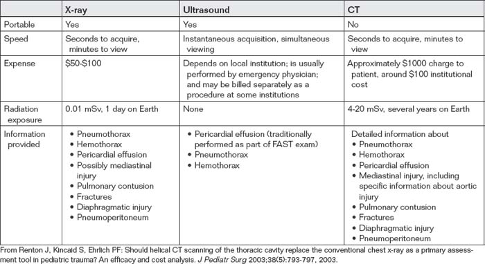
Chest x-ray is the most commonly used diagnostic modality for all forms of chest trauma. Benefits of chest x-ray include portability (allowing it to be used in the resuscitation bay without moving an unstable patient), speed of acquisition (seconds) and image availability (minutes), low expense (approximately $50 to $100), and low radiation exposure (0.01 mSv, equivalent to 1 day’s background exposure on Earth) (Table 6-1).
Clinical Decision Rules: Which Patients Require Chest X-ray?
Chest x-ray historically has been routinely recommended following blunt or penetrating chest trauma.1 However, a number of studies have examined the sensitivity of history and physical examination in detection of thoracic injury in children and adults. These studies suggest that in stable and alert blunt trauma patients, injuries are extremely rare with a normal thorax examination and the absence of chest complaints.
Bokhari et al.2 performed a prospective study of 523 stable patients with blunt trauma and 153 stable patients with penetrating trauma (Box 6-1). Before chest x-ray, patients were interviewed and examined for signs and symptoms of hemo- and/or pneumothorax, including chest pain or tenderness, tachypnea (greater than 20 breaths per minute), and abnormalities of bilateral lung sounds. Distracting injuries such as fractures or peritonitis were also noted.2 The authors found auscultation to be 100% sensitive for detection of hemo- and/or pneumothorax following blunt trauma. Chest pain and tenderness and tachypnea were insensitive (57% and 43%, respectively) but had negative predictive values of 99%. In the set of patients with penetrating chest trauma, history and examination were insufficient to exclude hemo- and/or pneumothorax. The authors conclude that stable blunt trauma patients with normal lung sounds and no chest pain, tenderness, or dyspnea do not require chest x-ray to evaluate for hemo- and/or pneumothorax. This study suffers from nonconsecutive enrollment with potential selection bias. Moreover, the rate of hemo- and/or pneumothorax in this population of blunt trauma patients was only 1.3% (7 of 523 patients), so negative predictive values provide a distorted view of the clinical value of history and physical exam. In a population with a higher rate of hemopneumothorax, the same sensitivity and specificity values would result in inadequate negative predictive values. Moreover, this study assessed the sensitivity of examination for hemo- and/or pneumothorax but did not assess for other important thoracic injuries such as mediastinal injury. In patients with a high-energy blunt injury mechanism suggesting possible mediastinal injury, the value of physical examination and history in excluding injury is uncertain. Nonetheless, in patients with a low-energy blunt trauma mechanism from which mediastinal injury is unlikely, a normal thoracic physical exam, and no complaints of chest pain, chest x-ray does not appear routinely necessary.
In children with blunt thoracic trauma (Box 6-2), Holmes et al.3 performed a prospective study of 986 patients below the age of 16 years to derive a clinical decision rule for detection of pulmonary contusion, hemothorax, pneumothorax, pneumomediastinum, tracheal–bronchial disruption, aortic injury, hemopericardium, pneumopericardium, blunt cardiac injury, rib fracture, sternal fracture, or any injury to the diaphragm. Of their population, 8.1% sustained a thoracic injury. The following
Box 6-1 Indications for Chest X-ray Following Chest Trauma
Adapted from Bokhari F, Brakenridge S, Nagy K, et al: Prospective evaluation of the sensitivity of physical examination in chest trauma. J Trauma 53(6):1135-1138, 2002.
features identified thoracic injuries: low age-adjusted systolic blood pressure, elevated age-adjusted respiratory rate, abnormal results of thorax exam, abnormal chest auscultation, femur fracture, and Glasgow Coma Scale score less than 15. Sensitivity was 98% with a 95% confidence interval (CI) of 91% to 100%, with a negative predictive value of 99.4% (95% CI = 97.9%-99.9%).3
Chest X-ray Technique and Limitations
For acute trauma patients, a portable chest x-ray is often the initial imaging test. The portable chest x-ray is performed as a supine or upright anterior–posterior (AP) examination (Figure 6-1). The supine examination
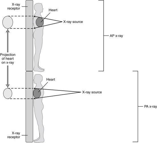
Figure 6-1 Differences between anterior–posterior (AP) and posterior–anterior (PA) chest x-rays.
The designation refers to the direction of passage of the x-ray beam through the patient to the receptor. The PA chest x-ray positions the x-ray source farther from the heart, and the x-ray receptor closer to the heart, than does the AP x-ray, resulting in less magnification of the cardiac silhouette relative to the thorax. This is explored in more detail in Chapter 5.
Box 6-2 Clinical Decision Rule for Chest X-ray in Pediatric Blunt Trauma Patients
Adapted from Holmes JF, Sokolove PE, Brant WE, et al: A clinical decision rule for identifying children with thoracic injuries after blunt torso trauma. Ann Emerg Med 39(5):492-499, 2002.
Chest x-ray is not required in the absence of these criteria:
Sensitivity 98%, negative predictive value 99.4%
is most commonly used in blunt trauma resulting from concern about possible coexisting spine trauma that would contraindicate an upright chest x-ray. On a chest x-ray obtained in the supine position, important diagnostic findings, such as subdiaphragmatic air indicating pneumoperitoneum or the layering fluid level of a hemothorax, may not be appreciated (Figures 6-2 through 6-10). Moreover, a supine portable chest x-ray exaggerates the apparent width of the heart and mediastinum, simulating cardiomegaly and potential mediastinal injury (see Figure 6-1). For all of these reasons, when possible, an upright chest x-ray should be performed. Particularly in penetrating chest or abdominal trauma, where spinal injury is less likely, an upright chest x-ray should be obtained to maximize detection of hemothorax (see Figures 6-2 through 6-10) and pneumoperitoneum (Figure 6-11). In patients who are completely stable hemodynamically and in whom a low suspicion for mediastinal injury exists based on factors such as low-energy trauma mechanism, a posterior–anterior (PA) and lateral chest x-ray should be obtained if a widened mediastinum on portable chest x-ray raises suspicion of mediastinal injury. In some cases, the mechanism of injury (e.g., a blow with fists to the anterior chest) is not consistent with mediastinal injury, and minor abnormalities on chest x-ray (e.g., a slightly widened mediastinum) may not require further imaging. If a high suspicion exists for mediastinal injury, chest CT with IV contrast should be performed, as the sensitivity of chest x-ray is inadequate to exclude mediastinal injury, as discussed in detail later in this chapter.
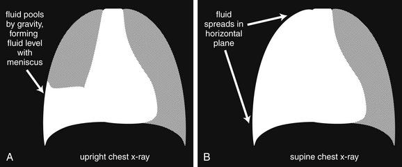
Hemothorax and nontraumatic pleural effusions are indistinguishable on chest x-ray, but a key difference in appearance may occur resulting from the use of supine chest x-ray in immobilized trauma patients. In the supine position, pleural fluid (blood or other pleural effusion) layers in the plane of the x-ray, providing a diffuse hazy appearance rather than the fluid level typical on an upright chest x-ray. A small amount of hemothorax may be difficult to appreciate, whereas a large hemothorax makes the affected side appear denser than the unaffected side. A diffuse pulmonary contusion could have a similar appearance. If an upright chest x-ray is obtained, the fluid layers and provides the same diagnostic appearance as a pleural effusion, with blunting of the costophrenic angle, and a meniscus sign at the interface with the chest wall. A, B, Schematic of how the same hemothorax could appear quite different depending on the patient’s position.
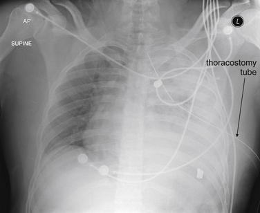
Figure 6-3 Hemothorax and pulmonary parenchymal injury.
This gunshot wound victim has a large hemothorax—despite having a thoracostomy tube in place. The patient is supine in this x-ray, so no layering fluid level is seen. Because blood and soft tissues, such as the heart, diaphragm, and spleen, share essentially the same density, none of the margins of these structures can be discerned where they abut one another. The most cephalad portion of the patient’s left thorax appears slightly less dense resulting from the presence of some aerated lung in this region. The two irregular radiopaque structures on the patient’s left are bullet fragments. Compare with the CT scan in Figure 6-4. Understand that not all hemothoraces require CT for management but we examine corresponding CT images to clarify chest x-ray findings.
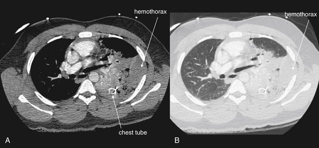
Same patient as Figure 6-3. This CT with IV contrast clarifies the findings on the chest x-ray. A, Soft tissue window. B, Lung window. The anterior portion of the left lung appears fairly normal (compare with the normal right lung). The posterior left thorax contains two separate denser substances: hemothorax and contused and atelectatic lung. On both the soft-tissue (A) and the lung (B) windows, the hemothorax is visible as a homogeneous collection along the inner aspect of the ribs. The injured lung has been compressed medially by the hemothorax and appears somewhat more heterogeneous resulting from the presence of both air and contrast-filled pulmonary vessels. The hemothorax is causing mass effect upon the heart, deviating it to the patient’s right. The chest tube is visible in cross-section as a bright ring.
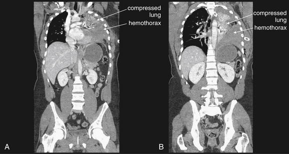
Figure 6-5 Hemothorax, CT with IV contrast.
Same patient as Figure 6-4. These coronal reconstructions were performed for evaluation of the spine, but they provide an interesting perspective on the extent of the hemothorax. Remember that although these images suggest a standing patient, they were acquired with the patient in a supine position. A, A somewhat more anterior plane than B. In both slices, the large hemothorax is seen, and the remaining lung tissue is compressed like an accordion in a medial and cephalad direction. Compare with the patient’s chest x-ray in Figure 6-3, also taken in a supine position. Now the dense left hemithorax makes sense, including the decreasing density in the upper lung field resulting from partially aerated lung. The left lung tissue is dense from a combination of compressive atelectasis and probable contusion from the patient’s gunshot wound—which are indistinguishable on CT, because both increase the density of lung tissue to a variable extent. Here, we know atelectasis plays a role, because the lung occupies a smaller-than-normal volume.
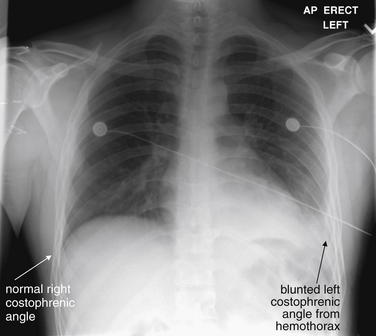
Figure 6-6 Hemothorax: Upright chest x-ray.
This 21-year-old male was stabbed in the left posterior thorax and had an oxygen saturation of 94%. This upright chest x-ray shows a blunted left costophrenic angle—compare with the normal right side. The diaphragm and heart border cannot be clearly identified, because blood, heart, and diaphragm share the same x-ray density (fluid density). Compare with Figure 6-7.
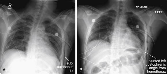
Figure 6-7 Hemothorax: Supine vs. upright chest x-ray.
Same patient as Figure 6-6. A, A supine film just after placement of a left chest tube. The left costophrenic angle appears clearer (and was interpreted by the radiologist as demonstrating decreased pleural fluid), but don’t be fooled. This x-ray was taken in a supine position; thus the fluid moved from its pooled dependent position in the costophrenic angle to a broadly distributed location in the horizontal, supine plane (as discussed in an earlier figure). How can we be sure that the chest tube had not resolved the fluid? B, An upright x-ray a few hours later. Again, the left costophrenic angle is obscured as the hemothorax collects in the dependent costophrenic angle. Incidentally, the thoracostomy tube in both figures takes a suboptimal course toward the diaphragm. Subcutaneous air is visible in the left chest wall from the chest tube placement.
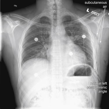
Figure 6-8 Hemothorax: Upright chest x-ray.
Same patient as Figure 6-7. This chest x-ray was performed 36 hours after the first, after removal of a chest tube that had been placed for both presumed pneumothorax and treatment of the hemothorax. The left costophrenic angle is sharp and distinct resulting from resolution of the hemothorax. This is an upright chest x-ray, so this changed appearance is not simply a result of the patient’s position. Subcutaneous air from the chest tube placement is visible as scattered black densities—compare the right and left chest walls. A few of these patches are labeled—try to identify more collections.
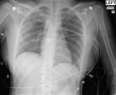
Figure 6-9 Hemothorax: Supine chest x-ray with a subtle density difference.
This supine x-ray shows a subtle increase in density of the right hemithorax compared with the left, indicating a hemothorax. This subtle change is sometimes described as a “veiling opacity.” Because of the supine position of the patient, the hemothorax does not pool in the costophrenic angle but rather distributes broadly across the entire right hemithorax. As a result, the costophrenic angle remains sharp. As you will see in the corresponding CT images in Figure 6-10, the total amount of fluid is relatively small, so the chest does not appear markedly denser. Can this appearance be distinguished from pulmonary contusion? The two may coexist, but an upright chest x-ray could confirm hemothorax by allowing fluid to become dependent, if the patient’s spine has been cleared. Incidentally, the patient has a right clavicle fracture.
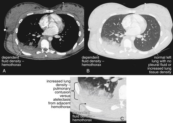
Figure 6-10 Hemothorax, CT with IV contrast.
Same patient as Figure 6-9. A, Soft-tissue window. B, Lung window of the same slice. C, Close-up from B. Dependent fluid is seen layering in the posterior right thorax—a hemothorax. The immediately adjacent lung appears dense as well; it is impossible on CT to distinguish the increased density of compressive atelectasis resulting from the hemothorax vs. actual pulmonary contusion. Compare with the patient’s normal left chest, where the lung is fully aerated even in the most posterior portion. Can we be sure that the increased density seen on the chest x-ray in the prior figure was a consequence of the hemothorax and not the dense lung? No; both contribute to the increased chest x-ray density.
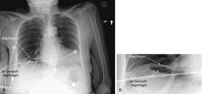
Figure 6-11 Pneumoperitoneum: Upright chest x-ray.
A, Upright chest x-ray. B, Close-up. An upright chest x-ray is the preferred view for detection of subdiaphragmatic air (pneumoperitoneum). On the supine view commonly obtained in blunt trauma, free air may not be visible, because it may collect in the anterior abdomen, rather than beneath the diaphragm.
Injuries that can be detected or suggested by chest x-ray (Table 6-2) include bony injuries such as rib fractures, clavicle fractures or dislocations, scapular fractures, and thoracic spinal injury; pneumothorax, hemothorax, possible tracheobronchial injury, pulmonary contusion, and subcutaneous emphysema; mediastinal abnormalities, including cardiomegaly suggesting pericardial effusion, pneumopericardium, and a host of findings suggesting aortic injury; diaphragmatic injuries; pneumoperitoneum; and retained foreign bodies, such as bullet fragments.
TABLE 6-2 Injuries Detected or Suggested by Chest X-ray25,98,109
| Injury Type | Specific Injury or Finding | Sensitivity |
|---|---|---|
| Bony injuries | Varies depending on degree of displacement. | |
| Injuries to the lungs, pleura, or airways | Varies depending on degree of injury. Controversy exists about the necessity for explicit diagnosis and treatment of subtle injuries not evident on chest x-ray. Chest x-ray has been reported to be only 45% sensitive for pneumothorax compared with CT, but the necessity for treatment of CT-only pneumothoraces is unclear. | |
| Mediastinal and cardiac injuries | Around 86%-93% sensitive for aortic injury. | |
| Diaphragmatic injuries | Around 60%. | |
| Abdominal injuries | Varies with degree of pneumoperitoneum. Sensitivity is reportedly around 38% for any pneumoperitoneum but as low as zero in patients with minimal free air (1-mm air pockets) and as high as 100% in patients with ≥13-mm collections. | |
| Foreign bodies | Varies depending on size and density of object. |
From Ball CG, Kirkpatrick AW, Laupland KB, et al. Factors related to the failure of radiographic recognition of occult posttraumatic pneumothoraces. Am J Surg 189(5):541-546, 2005; discussion 546; Smithers BM, O’Loughlin B, Strong RW. Diagnosis of ruptured diaphragm following blunt trauma: Results from 85 cases. Aust N Z J Surg 61(10):737-741, 1991; Stapakis JC, Thickman D. Diagnosis of pneumoperitoneum: Abdominal CT vs. upright chest film. J Comput Assist Tomogr 16(5):713-716, 1992.
Recent studies suggest that chest x-ray is relatively insensitive for a variety of clinical injury patterns. However, detecting radiographically occult injuries with more advanced diagnostic modalities such as CT scan may not always result in clinical benefits to patients. For example, when a hemothorax is visible on chest CT but not on chest x-ray, it is uncertain whether thoracostomy tube drainage is routinely necessary.
Interpretation of Chest X-ray for Trauma
Chest x-ray interpretation in the setting of trauma must be performed rapidly and systematically. Using a checklist of critical pathology can help you avoid the pitfall of stopping interpretation after recognition of a single abnormality. We review a few important points about the AP portable chest x-ray technique relevant to interpretation, and then we proceed with systematic interpretation.
The usual technique for acquisition of chest x-ray in blunt trauma is a supine AP portable chest x-ray. This technique allows maintenance of spinal precautions in patients with possible spine trauma, and it is appropriate for unconscious patients who are unable to sit or stand. The AP supine technique has several consequences:
In penetrating trauma, an upright chest x-ray is often obtained in stable patients, increasing the sensitivity for pneumoperitoneum and hemothorax. However, the AP portable technique still results in an enlarged cardiac and mediastinal silhouette, as described earlier. With these features in mind, we review a systematic approach to interpretation of the chest radiograph. Many approaches have been described, and any approach that allows rapid but comprehensive assessment is appropriate. Table 6-3 reviews a common mnemonic for interpretation of chest x-ray, which we introduced in Chapter 5.
TABLE 6-3 Mnemonic for Systematic Interpretation of Chest X-ray in Trauma110
| A | Airway |
| B | Bones and Breast Shadows |
| C | Cardiac Silhouette
• Assess the cardiac silhouette for general size and contour.
• Note the width of the mediastinum. Other abnormal mediastinal findings are reviewed in more detail in Table 6-4.
|
| D | Diaphragm |
| E | Everything Else |
| F | Lung Fields
• Review the lung fields themselves, looking for evidence of pneumothorax, pulmonary contusion, hemothorax, or herniated abdominal contents, suggesting diaphragm rupture.
|
| F | Foreign Bodies or Devices |
From Crausman RS. The ABCs of chest X-ray film interpretation. Chest 113:256-257, 1998.
Pneumothorax and Tension Pneumothorax
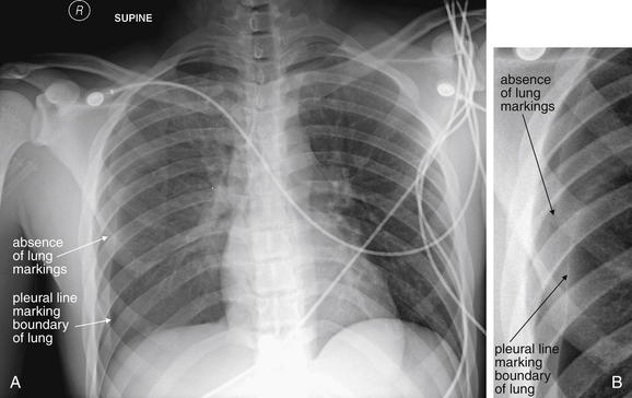
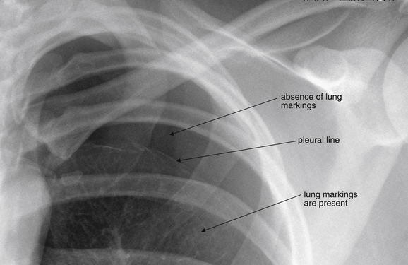
A pneumothorax is evident on chest x-ray as an area of increased lucency at the periphery of the lung. The normal lung markings are absent, giving the region of pneumothorax an unusually black appearance compared with the normal appearance (Figures 6-12 through 6-23). Comparison with the contralateral side is useful, although bilateral pneumothoraces may be present. In some cases, the lung edge (visceral pleura) may be visible as a discrete line (see Figures 6-12, 6-13, 6-16, 6-20, and 6-21). The average distance from the ipsilateral thoracic cage to the pleural surface (based on three linear measurements) on upright chest x-ray has been described as predicting pneumothorax volume.5
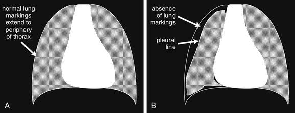
A, Schematic of normal lung. B, Schematic of pneumothorax. Pneumothoraces can range in size from tiny to massive—we examine some tension pneumothoraces in later figures. Because of the variability in their size and location, pneumothoraces can be difficult to detect on chest x-ray. For example, a pneumothorax that is anterior or posterior rather than lateral may be hidden on frontal chest x-ray, particularly one taken in the supine position. An upright chest x-ray should be obtained if possible. An expiratory film is thought to be more sensitive, because the lung and thorax decrease in size during expiration, but air trapped in the pleural space remains the same size and thus appears relatively larger. Subtle pneumothoraces may not be visible on chest x-ray. In some cases, subcutaneous air may be the only visible clue to underlying lung injury. CT is extremely sensitive for pneumothorax, although controversy remains over the proper management of pneumothoraces seen only on CT (see text). Ultrasound is also thought to be more sensitive than chest x-ray for detection of pneumothorax, although again, the management of pneumothorax seen only on ultrasound is uncertain, because this is a relatively newly described method of detection. The chest x-ray findings of pneumothorax include a lack of the normal lung markings, which should be visible to the periphery of the chest wall. Sometimes a line marking the boundary of the lung and visceral pleura is visible, although this can be confused with ribs and with the medial margin of the scapula. Depending on the degree of pneumothorax and lung collapse, the lung parenchyma may appear denser than the opposite side. In extreme cases of tension pneumothorax, the pressure exerted by the air in the pleural space may begin to displace other structures, including the diaphragm and mediastinum. In tension pneumothorax, the hyperinflated hemithorax may also have abnormally positioned ribs, with a position more horizontal than usual. Review the figures that follow for examples of varying degrees of pneumothorax. Subtle cases can be hard to reproduce in print.
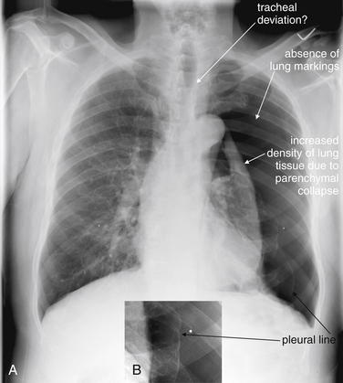
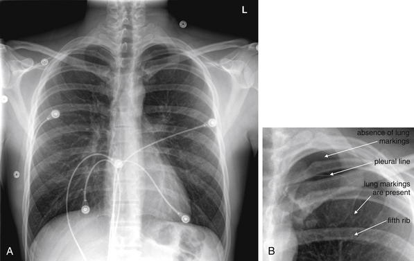
A, PA x-ray demonstrating a very large spontaneous pneumothorax. B, Close-up from A. This image demonstrates the classic features described in Figure 6-12 no lung markings to the periphery of the thorax, a visible visceral pleural line, and increased density of the lung parenchyma—resulting from the marked degree of collapse in this case. Is this a tension pneumothorax? Some would argue that the definition of tension pneumothorax is clinical, based on hypotension and exam findings such as jugular venous distension and tracheal deviation. On a radiographic basis, tension pneumothorax is marked by some combination of tracheal deviation, mediastinal deviation to the opposite side, depression of the diaphragm and a deep sulcus (costophrenic angle), and elevation of ribs to a more horizontal position. This patient may have slight tracheal deviation and a degree of mediastinal shift, but the diaphragm appears normal, there is no deep sulcus sign, and the ribs are oriented normally. The white dots seen on each side are nipple markers.
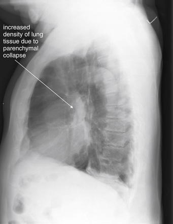
Same patient as Figure 6-13. The lateral chest x-ray is not usually diagnostic, even in dramatic cases such as this one, because the normal thorax is superimposed upon the abnormal. Here, a hint of the complete collapse of the left lung is seen, with increased density near the hilum, but the lateral x-ray is neither necessary nor particularly helpful in this case.
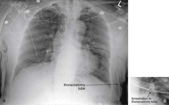
The same patient as Figures 6-13 and 6-14 after placement of a thoracostomy tube and reexpansion of the left lung. A, AP chest x-ray. The mediastinum appears wider than in Figure 6-13 because of the AP technique in this x-ray. B, Close-up from A. Although the chest tube placement appears a bit suboptimal, it clearly is functioning, because there is complete resolution of the abnormalities noted on the original x-ray. The thoracostomy tube shows typical features including a radiopaque line, punctuated by breaks marking the location of its fenestrations (B).
A, Supine portable chest x-ray. B, Close-up from A. This moderate pneumothorax is much subtler than in Figure 6-13 but demonstrates many of the same findings. A pleural line is faintly visible—beyond this line, no lung markings are visible. Compare this with the opposite side, where the fine markings of pulmonary blood vessels are seen to the periphery of the pleural space. Although the normal result of a pneumothorax is a more lucent hemithorax, the entire right thorax appears somewhat denser in this case; the CT from the same patient in Figure 6-18 illustrates why. It is a good practice to find and follow the scapular border and rib borders to avoid confusion of these lines with the pleural line of a pneumothorax. None of the findings of a tension pneumothorax are present in this chest x-ray. The right costophrenic angle and lateral diaphragm are somewhat indistinct. This, plus the density of the right hemithorax, should make you consider hemothorax or pulmonary contusion, in addition to the pneumothorax.
Same patient as Figure 6-16. A chest tube has been placed, and the previously seen pleural line and absence of lung markings have resolved. The right chest looks somewhat less dense than before.
This CT with IV contrast was performed for evaluation of the mediastinum. Chest CT is not routinely needed for evaluation of pneumothorax. Nonetheless, it reveals several interesting findings. First, despite the chest tube, a pneumothorax remains (remember, air is black on all CT windows), and this was not seen on the supine chest x-ray in Figure 6-17. Why not? The pneumothorax is anterior, so the lung tissue intervening between the x-ray tube and the detector plate prevented recognition of the pneumothorax. The posterior lung tissue is quite dense, and a tiny amount of pleural fluid is present—likely indicating pulmonary contusion and small hemothorax. Alternatively, the posterior lung tissue may be dense resulting from atelectasis. This seems less likely because the left lung does not demonstrate dependent atelectasis. Does the residual pneumothorax require treatment? It will likely resolve with continued use of the existing chest tube, though that chest tube should be examined for kinks and checked for the presence of a continued air leak. When a large pneumothorax persists despite a properly functioning thoracostomy tube, a large airway injury or pulmonary laceration should be suspected.
This young male suffered a spontaneous left pneumothorax. The x-ray demonstrates several features typical of pneumothorax and is subtle, though the pneumothorax is relatively large. This pneumothorax appears to be restricted to the left apical region on this upright chest x-ray. There is an absence of lung markings, and the apical thorax appears more lucent than usual resulting from the absence of lung parenchyma. A faint pleural line can be seen. A close-up (Figure 6-20) shows these findings better.
Same patient as Figure 6-19, spontaneous apical pneumothorax. The absence of lung markings is clear, and the pleural boundary can be seen.
Same patient as Figures 6-19 and 6-20. A, Frontal chest x-ray. B, Close-up from A. Needle aspiration of the pneumothorax was performed, and this x-ray was obtained 6 hours later. A small residual pneumothorax is present (B), although lung markings are now visible above the fifth rib, where they were not previously.
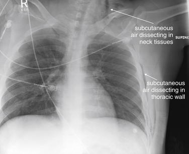
Figure 6-22 Pneumothorax with subcutaneous air on chest x-ray but no visible pneumothorax.
This trauma patient has no visible pneumothorax, with lung markings seen to the periphery. However, subcutaneous air (black) in the lateral left chest wall and neck indicate some form of lung or airway injury, as the patient had no external wounds through which air might have been introduced. Subcutaneous air of this degree, while essentially proving the existence of some respiratory (or less likely, aerodigestive tract) injury, would not mandate CT. For example, in a patient with spontaneous chest pain after cough, CT should not be performed to hunt for associated pneumothorax, although a pneumothorax should be suspected. In this case, chest CT was performed to evaluate for possible thoracic spine injury but incidentally provided more information about the source of the subcutaneous air and is reviewed in Figure 6-23.
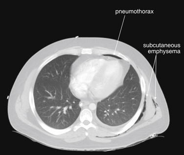
Figure 6-23 Small pneumothorax with subcutaneous air on CT with IV contrast.
Same patient as Figure 6-22. A tiny anterior pneumothorax is visible, as well as some dependent pleural fluid, which is likely hemothorax in the setting of trauma. The subcutaneous air is readily visible on lung windows. How should small pneumothoraces seen only on chest CT be managed? Controversy exists (see text). In general, very small pneumothoraces such as this should not be treated. Some authors advocate prophylactic placement of a thoracostomy tube if the patient will be transported long distances, transported by air, or placed on positive-pressure ventilation, which could result in an enlarging pneumothorax. Small studies show a low risk of increasing pneumothorax with positive-pressure ventilation, though this is an obvious complication that must be anticipated.
A common pitfall is mistaking the medial border of the scapula for such a pleural line or, conversely, mistaking a pneumothorax for a scapular marking. In cases of very large pneumothorax, the lung may be seen as a density contracted medially toward the lung hilum. Although this is a dramatic and overt finding, to the inexperienced viewer, it may not be recognized without forewarning of this possibility (see Figure 6-13).
Large pneumothoraces can exert pressure effects, resulting in clinically important hemodynamic compromise. Medical dogma states that a tension pneumothorax should never be recorded on x-ray, as it should be treated empirically as soon as suspected. In reality, some large pneumothoraces are difficult to detect clinically, and some patients remain stable despite radiographic appearances suggesting tension pneumothorax. Classic findings of pressure effects associated with tension pneumothorax include the following (Figures 6-24 through 6-28):
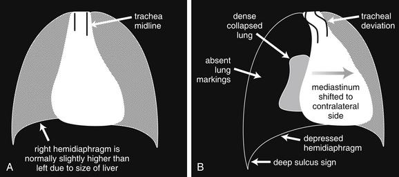
Figure 6-24 Tension pneumothorax on chest x-ray.
A, The normal chest. B, Schematic of tension pneumothorax. In the case of a tension pneumothorax, a large pneumothorax is typically visible, with a dense-appearing, medially displaced, collapsed lung. Increased pressure results in mediastinal shift and tracheal deviation to the opposite side. The affected side has a depressed hemidiaphragm. If tension pneumothorax occurs on the right side, the right hemidiaphragm may be displaced in a caudad direction and may be lower than the left hemidiaphragm—the reverse of their normal positions. In addition, the costophrenic angle may be extremely deep on the abnormal side (the deep sulcus sign).
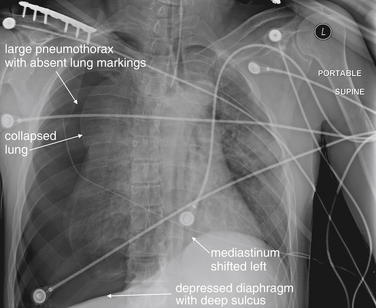
Figure 6-25 Tracheobronchial injury with tension pneumothorax.
This 46-year-old male presented unresponsive after a motorcycle collision and was noted to have decreased breath sounds with tachycardia and a blood pressure of 120/80. The patient was intubated and chest x-ray was performed, showing findings concerning for tension pneumothorax. Findings included a large pneumothorax, a dense and medially contracted lung, a deep sulcus sign, a flattened diaphragm, and a shift of the mediastinum to the left. Figure 6-26 shows the patient’s chest x-ray after thoracostomy tube placement. His CT (Figure 6-27) suggested a tracheobronchial injury. Bronchoscopy confirmed transection of the bronchus just distal to the takeoff of the right main bronchus. This was repaired operatively.
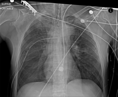
Figure 6-26 Tracheobronchial injury with tension pneumothorax.
Same patient as in Figure 6-25. After placement of a right thoracostomy tube, the patient’s findings of tension pneumothorax have resolved.
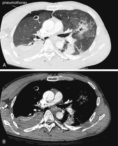
Figure 6-27 Tracheobronchial injury with tension pneumothorax.
Same patient as in Figures 6-25 and 6-26. This CT with IV contrast suggests but does not prove a tracheobronchial injury. A moderate-size pneumothorax persists despite the right thoracostomy tube, implying that more air is leaking into the pleural space than can be removed by the chest tube. Explanations for this include a large airway injury, a significant pulmonary parenchymal laceration, or a malfunctioning chest tube that is kinked, is plugged, is not attached to suction, or does not have its fenestrations within the pneumothorax. The pneumothorax is visible on the lung window (A) but not on the soft-tissue window (B). Other injuries are present but are discussed separately in other figures—return to this figure later and try to identify pleural fluid (hemothorax), pulmonary contusion, rib fractures, and subcutaneous emphysema. This patient was taken to the operating room, where a bronchial injury was confirmed by bronchoscopy.
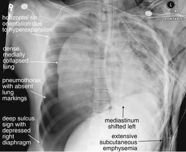
Figure 6-28 Tracheobronchial injury with tension pneumothorax.
This 19-year-old female struck a telephone pole and was unresponsive at the accident scene. Emergency medical services providers attempted to decompress a suspected left tension pneumothorax. The patient arrested en route to the emergency department, and on arrival a left chest tube was placed, just before this x-ray. The x-ray shows classic findings of tension pneumothorax, with a deep sulcus sign (so deep that the complete sulcus is not visible on the x-ray). The mediastinum is deviated to the left. The right ribs have assumed an abnormally horizontal position resulting from hyperexpansion of the chest. A left chest tube is present, and extensive subcutaneous air is present (compare with the normal right chest wall). Compare these findings to the CT images in Figure 6-29.
Tracheobronchial Injury
Tracheobronchial injury (see chest x-rays and related CTs, Figures 6-25 through 6-30) is a rare but life-threatening injury usually associated with large or tension pneumothorax and requiring surgical intervention. Clues to the presence of this injury include the persistence of a large or even tension pneumothorax despite the apparently appropriate placement of a thoracostomy tube.6 This finding indicates that the rate of air leaking into the pleural space exceeds the rate at which it is being removed from that space by the thoracostomy tube. Two possibilities explain this scenario:
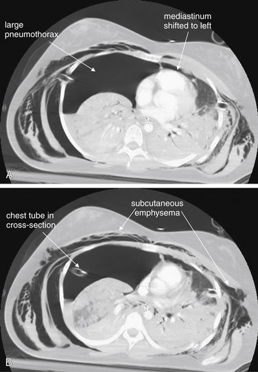
Figure 6-29 Tracheobronchial injury with tension pneumothorax: CT with IV contrast viewed with lung windows.
A, B, Two sequential axial images. Same patient as in Figures 6-28 and 6-30. This CT is highly suggestive of tracheobronchial injury. A right chest tube has been placed and is clearly seen entering the right pleural space. Despite this, a large tension pneumothorax is still present. The mediastinum remains deviated to the left. The most likely explanation is a large airway injury, which would allow air to enter the pleural space faster than it can be removed by a large-bore chest tube. An alternative explanation would be complete occlusion of the chest tube by kinking or internal plugging. The patient is intubated and receiving positive pressure ventilation, increasing the risk that a bronchial injury would result in tension pneumothorax. Massive subcutaneous emphysema has accumulated bilaterally.
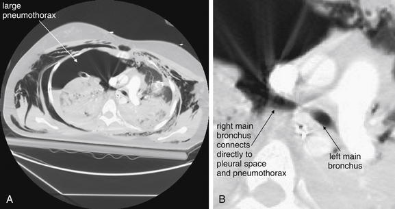
Figure 6-30 Tracheobronchial injury with tension pneumothorax.
CT with IV contrast, lung windows. A, Axial CT image. B, Close-up from A. Same patient as in Figures 6-28 and 6-29. The actual tracheobronchial injury is seen. The right main bronchus is seen in direct continuity with the large pneumothorax in right pleural space.
A rarer but more specific sign of tracheobronchial injury is the fallen lung sign, in which the collapsed lung falls away from the mediastinum rather than being retracted medially toward the hilum as a consequence of bronchial transection (see Figure 6-30).6
Tracheobronchial and esophageal injuries are rare following blunt trauma (occurring in only about 1%) but may be suggested by CT.7 In cases of tracheobronchial injury, chest x-ray may be nondiagnostic in 30%, whereas CT may show a defect in the wall of major airways. Air in the airway may be contiguous with that in the pleural space or mediastinum when viewed with CT lung windows.8 In cases of esophageal injury, CT may show pneumomediastinum and esophageal thickening at the level of injury (see Figure 6-36). A Gastrografin swallow study followed by barium swallow can be diagnostic.7 Imaging of the esophagus is discussed in more detail in Chapter 4. If aerodigestive injuries are suspected but the source of the air leak is unclear from diagnostic imaging, bronchoscopy and esophagoscopy can be used to differentiate the source.
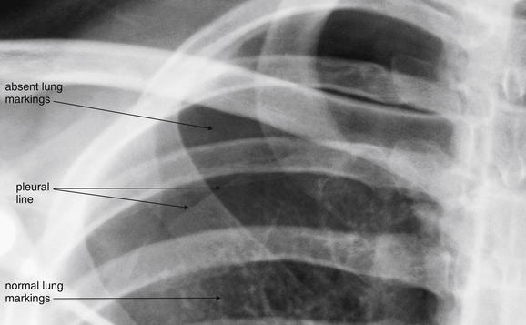
Figure 6-31 Pneumothorax, comparison of chest x-ray and ultrasound findings.
This 19-year-old male had spontaneous right chest pain while playing soccer. This close-up from his chest x-ray shows a moderate apical right pneumothorax. Lung markings are absent at the right apex, and a pleural line is visible.
Ultrasound images from the same patient are shown in Figures 6-32 through 6-34.
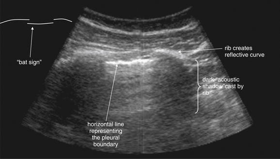
Figure 6-32 B mode ultrasound findings of normal lung and pleura.
The normal left lung from the patient in Figure 6-31, viewed with B mode ultrasound. The anterior cortices of two adjacent ribs are visible as echogenic, horizontally oriented curves. Deep to these are acoustic shadows cast by the ribs. Between the ribs lies the horizontal pleural line, a bright white reflection at the interface between the parietal and the visceral pleura. Some authors have described the three lines formed by two adjacent ribs and the pleural line as the bat sign resulting from its resemblance to a stylized line drawing of a bat in flight (diagrammed in figure margin; try to identify this for yourself in the ultrasound image). When real-time ultrasound images are viewed, horizontal motion along the pleural line is normally seen—the sliding lung sign. In the presence of pneumothorax, movement along this line is not seen, as the visceral pleura is separated from the parietal pleura by a buffer of air.
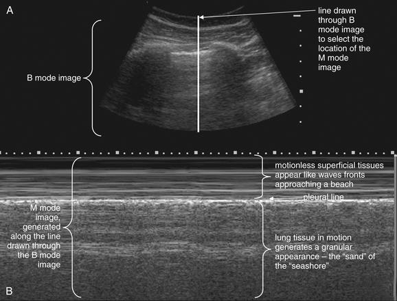
Figure 6-33 M mode ultrasound findings of normal lung and pleura—seashore sign.
Figures 6-31 through 6-34 show images from the same case. Most ultrasound machines allow simultaneous acquisition of a B mode image (A) and an M mode image (B) that represents motion through the line in the B mode image. An M mode image of the normal left lung shows the seashore sign. Motionless tissues superficial to the pleural line have the appearance of a laminated series of horizontal lines, like wave fronts approaching a seashore. Deep to the pleural line, respiratory motion of normal lung gives a granular appearance—the “sand” on the sea shore.
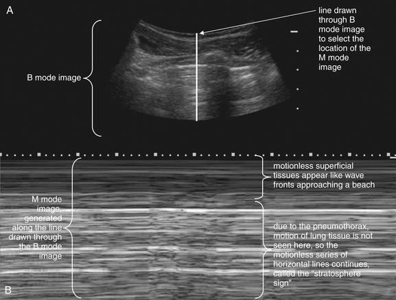
Figure 6-34 M mode ultrasound findings of pneumothorax.
Figures 6-31 through 6-34 show images from the same case. Most ultrasound machines allow a split screen mode, showing B mode (typical two-dimensional images, A) and M mode (motion mode, B) on the same screen. In this figure, a B mode image of the chest wall is seen in the upper portion of the screen, A. An acoustic shadow from a rib is visible, just to the right of the vertical white line. This line has been drawn by the emergency ultrasonographer through the pleura between two ribs. Motion along this line is then depicted in the M mode image in B. The M mode image of the abnormal right lung shows the stratosphere sign, consistent with pneumothorax. Most ultrasound machines allow simultaneous acquisition of a B mode image (A) and an M mode image (B), representing motion through the line in the B mode image.
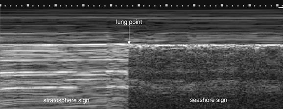
Figure 6-35 Ultrasound findings of normal lung and pneumothorax.
A lung point sign is simulated in this figure. When an M mode image reveals a transition between the abnormal stratosphere sign and the normal seashore sign, this is called the lung point sign. It is an indication of a partial pneumothorax, with the lung surface intermittently contacting the thoracic wall. Compare with Figures 6-33 and 6-34.
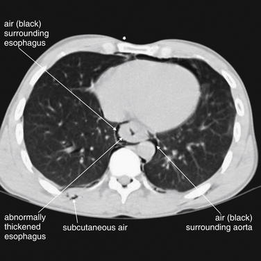
Figure 6-36 Esophageal tear with pneumomediastinum.
CT can demonstrate esophageal injuries following trauma. These are extremely rare following blunt trauma but can occur with penetrating chest trauma. In the case of thoracic gunshot wounds, CT can demonstrate the missile trajectory, indicating its proximity to the esophagus and other mediastinal structures. In addition, focal thickening of the esophagus may be seen at a site of injury. Air leaking from an esophageal injury can create pneumomediastinum visible on CT. In this patient, who has an esophageal injury not from external trauma but from forceful vomiting, the esophagus appears thickened and air is visible surrounding the esophagus (pneumomediastinum). Lung windows reveal air and, in the case of trauma, can reveal a missile trajectory by demonstrating injured lung parenchyma.
Subcutaneous Air
Subcutaneous air, while itself almost never life-threatening, should be carefully sought because it can provide clues to other important injuries including pneumothorax. The appearance is increased lucency (black appearance) in soft tissues resulting from the presence of low-density air. The appearance can be extremely subtle (see Figure 6-22) or grossly evident (see Figure 6-28), with air outlining muscle fibers and multiple tissue planes. The chest wall, axilla, and neck should be thoroughly inspected. Air within soft tissue can have several sources:
Hemothorax
Hemothorax may be subtle (see Figure 6-6) or gross (see Figure 6-3) on chest x-ray. Technically, chest x-ray reveals the presence of pleural fluid but does not prove it to be blood; a preexisting pleural effusion would have an identical radiographic appearance. The clinical setting is essential to determining the course of action. As described earlier, the commonly used supine portable chest x-ray can compromise detection of hemothorax by causing fluid to layer in the plane of the horizontally positioned x-ray detector. Small amounts of hemothorax may be invisible on supine x-ray; on upright x-ray, these may appear as simple blunting of the costophrenic angles (see Figures 6-2 through 6-10). Large hemothoraces may give the entire thorax a denser (whiter) appearance relative to the normal side on supine x-ray, sometimes referred to as a “veiling opacity” (see Figure 6-9). On upright AP or PA chest x-ray, these may appear as obvious radiodense layered fluid collections with a curved meniscus where they meet the thoracic wall (see Figure 6-7). Other chest x-ray findings commonly associated with hemothorax include pneumothorax, rib fractures, pulmonary contusions, mediastinal injury, and spinal trauma. Large hemothoraces can obscure underlying pulmonary contusions. The diaphragm on the affected side may be obscured, and the possibility of concurrent diaphragmatic injury must be considered. Diaphragm injuries are discussed in more detail later in this chapter and in Chapter 10. Particularly in the case of penetrating trauma, the subdiaphragmatic area should be assessed for pneumoperitoneum.
Pulmonary Contusion and Laceration
Pulmonary contusion, laceration, and hematoma refer to pulmonary parenchymal injuries that result in hemorrhage into the alveolar space and into interstitial spaces. In blunt trauma, the term contusion is common; in penetrating trauma, the term laceration is more often used, though the chest x-ray appearance is the generally the same. The accumulation of blood, other fluid, and cellular debris increases the density of the normally air-filled alveolar space, making it appear white on chest x-ray (chest x-rays and related CTs, Figures 6-37 through 6-46).9 The interstitial spaces also become more prominent. The affected lung tissue takes on the appearance of a solid organ or fluid. Much confusion exists about the appearance of pulmonary contusion on chest x-ray and the time course over which pulmonary contusion becomes radiographically apparent. Some authors have stated that pulmonary contusion may not be evident for hours, but a more common sense explanation must be understood: If sufficient hemorrhage and injury to lung has occurred to increase the density of the tissue, the injury is immediately apparent on chest x-ray. If a lesser degree of injury is present such that the density of the tissue remains relatively normal, the injury may be invisible initially. If continued hemorrhage or fluid accumulation into the injured tissue occurs, the appearance may become more evident over hours. Pulmonary contusion has no pathognomonic features; the same increased density can occur with pneumonia, aspiration, or pulmonary infarction—all processes that can result in alveolar consolidation. The context of trauma defines the appearance as contusion rather than one of these other processes. It is impossible to distinguish an evolving pulmonary contusion on chest x-ray from a pneumonia developing in the region, because both become visible on chest x-ray by the same process of alveolar and interstitial fluid accumulation. Clinical factors such as the presence of fever are used to make the distinction, which may be impossible even on these grounds. Pulmonary contusion, aspiration, and pneumonia may occur simultaneously. Associated chest x-ray findings can include rib fractures, hemo- or pneumothorax, or radiodense foreign bodies in the setting of penetrating trauma. CT is more sensitive than x-ray and may predict the need for ventilatory support—although it is the clinical state of the patient, not imaging findings, that defines the need for intervention.9
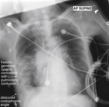
Figure 6-37 Pulmonary contusion.
This 77-year-old female was in a car struck by a train. Her chest x-ray shows dense consolidation of the right mid- and lower lung. The costophrenic angle is blunted, and the lateral right diaphragm appears elevated and cannot be distinguished from the consolidation. From Chapter 5, recall the silhouette sign, the principle that two adjacent tissues of the same density cannot be distinguished on chest x-ray. Because the right lateral and lower lung cannot be distinguished from the diaphragm and liver in this patient, they must share the same soft-tissue (fluid) density. Figure 6-38 demonstrates CT images from this patient. Can pulmonary contusion be distinguished from aspiration or other pneumonia? Not based on the chest x-ray findings. Theoretically, this patient could have aspirated—or could have had pneumonia before her collision with the train.
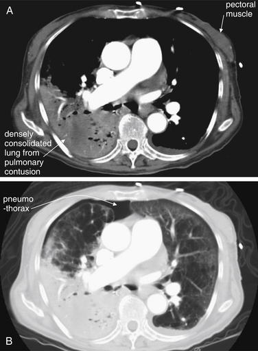
Figure 6-38 Pulmonary contusion.
This 77-year-old female was in a car struck by a train. Compare these CT with IV contrast images with Figure 6-37 showing her chest x-ray. A, Soft-tissue window settings. B, Lung window settings. These images demonstrate that the injured right lung has taken on the same tissue density as muscle tissue—a remarkable transformation of lung to “solid organ.” On soft-tissue window settings, the lung tissue and pectoral muscle appear nearly the same density. The contused lung parenchyma increased in density resulting from alveolar hemorrhage and fluid leaking from injured lung parenchymal cells. Compare with the fairly normal appearance of the left lung on lung windows. Note the different information provided by the two window settings. The lung window setting demonstrates a pneumothorax that is not visible on the soft-tissue window. Incidentally, the anterior right lung shows extensive bullous changes of emphysema, discussed in more detail in Chapter 5.
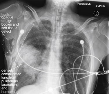
Figure 6-39 Pulmonary laceration or hemorrhage.
Not all pulmonary injuries are contusions from blunt trauma. This 46-year-old male was shot in the right axilla by police. Bullet fragments are visible in the soft tissues of the right axilla, where a large soft-tissue defect is visible. The lung parenchyma is densely consolidated in the trajectory of the bullet—presumably from bleeding into the damaged tissue. The silhouette sign is again seen; the injured lung parenchyma of the right middle lobe is adjacent to the right heart border and shares the same soft-tissue (fluid) density. As a consequence, the right heart margin is obscured. A chest tube has been placed, and no hemopneumothorax is visible, although the supine position of this chest x-ray reduces its sensitivity for these, as described in an earlier figure.
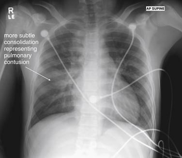
Figure 6-40 Pulmonary contusion.
This 16-year-old male was a restrained passenger in a motor vehicle collision. He self-extricated and ambulated at the scene but complained of chest pain. His chest x-ray shows a subtle consolidation of the right mid lung. The flexible chest wall of pediatric patients may allow lung contusion without rib fracture.
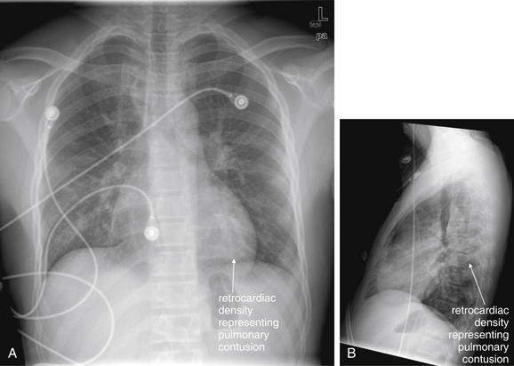
Figure 6-41 Pulmonary contusion.
Same patient as in Figure 6-40. A, PA chest x-ray. B, Lateral chest x-ray. This chest x-ray was taken 7 hours after the first and shows an evolving pulmonary contusion. Compare with the CT in Figure 6-42.
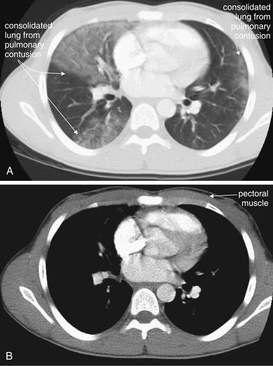
Figure 6-42 Pulmonary contusion: CT with IV contrast.
Same patient as Figures 6-40 and 6-41. This patient has a subtler pulmonary contusion than does the victim of the car–train collision (Figures 6-37 and 6-38). In those figures, the lung tissue was so densely consolidated that it was easily visible on both chest x-ray and CT soft-tissue windows, with the same apparent density as pectoral muscle. The patient in this figure has less severe injury, with less dense lung tissue in the region of injury. Whereas the injured lung is readily visible on lung windows (A), it is invisible on soft-tissue windows (B). Bilateral pulmonary contusions are visible on CT, whereas the initial x-ray demonstrated only the right-sided contusion clearly.
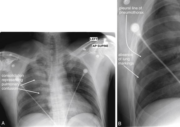
Figure 6-43 Pulmonary contusion with pneumothorax.
A, AP supine chest x-ray. B, Close-up from A. This 34-year-old male was an unrestrained driver who was thrown through his windshield. His chest x-ray shows a pulmonary contusion with density along the superior right heart border. Careful inspection also reveals a lateral right pneumothorax (B). The width of the upper mediastinum cannot be determined because of the adjacent dense right lung apex. Therefore, CT was performed to evaluate for mediastinal hematoma and aortic injury (Figure 6-44).
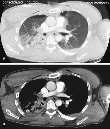
Figure 6-44 Pulmonary contusion with pneumothorax.
Same patient as Figure 6-43. A, CT with IV contrast, axial slice viewed with lung windows. B, Same slice, viewed with soft-tissue windows. Some areas of injured lung are densely consolidated and are visible even on soft-tissue windows. Others are less dense, reflecting less alveolar hemorrhage and parenchymal injury—these are visible only on lung windows (A). A small right anterior pneumothorax persists despite the presence of a chest tube, and a small left pneumothorax is present. The pneumothoraces are not visible on soft-tissue windows (B).
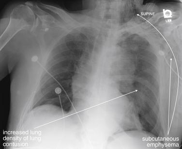
Figure 6-45 Pulmonary contusion with pneumothorax.
This 89-year-old male was in a motor vehicle collision in which his airbags deployed. The patient’s chest x-ray shows extensive subcutaneous emphysema of the left chest wall, extending to the left neck. His left lung appears denser than the right, suggesting pulmonary contusion. A small basilar left pneumothorax is difficult to see on this image but is the likely source of the subcutaneous air.
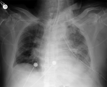
Figure 6-46 Pulmonary contusion with pneumothorax.
Same patient as Figure 6-45, 2 days later. Does this x-ray show progression of pulmonary contusion? It is hard to be sure. The patient has a chest tube in place and may have a hemothorax contributing to increased left lung density. He is intubated, and a ventilator-associated pneumonia may be in progress as well. Upright portable chest x-ray cannot differentiate these causes of increased lung density.
Lobar Collapse
Following trauma or as a consequence of endotracheal intubation, lobar collapse with volume loss can occur. Familiarity with the chest x-ray appearance is essential, because this condition can be mistaken for other serious abnormalities, including mediastinal trauma, tension pneumothorax, pulmonary contusion, hemothorax, and diaphragm rupture. Treatment includes maneuvers to reexpand the affected lung segment, sometimes including repositioning of an endotracheal tube or altering ventilator settings. A collapsed lung segment appears dense on chest x-ray (Figure 6-47 and CT Figure 6-48), similar in appearance to other parenchymal abnormalities, such as pulmonary contusion, or to pleural space abnormalities, such as hemothorax. However, because a collapsed lung segment occupies a smaller-than-normal volume, radiographic evidence of volume loss is present. Findings of volume loss include shift of structures toward the area of volume loss. This can include shift of the mediastinum, tracheal deviation, and elevation of the diaphragm on the affected side (see Figure 6-47). This is in stark contrast to tension pneumothorax, where structures are shifted away from the affected side. Nevertheless, to an inexperienced observer, the obvious shift of structures may be mistaken for tension pneumothorax. Elevation of the diaphragm can be mistaken for a diaphragmatic injury. If the area of lobar collapse abuts the mediastinum, the mediastinum may appear wide, simulating aortic trauma. In an intubated patient, the position of the endotracheal tube should be noted. Right main bronchus intubation commonly can result in left lung collapse or right upper lobe collapse (because the endotracheal tube may occlude the right upper lobe bronchus). Plugging of bronchi with blood, mucus, or aspirated material can also lead to lobar collapse.
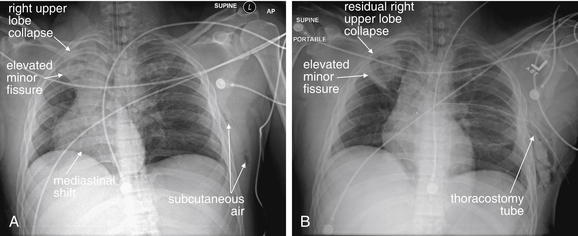
Figure 6-47 Lobar collapse with mediastinal shift resulting from volume loss.
This 38-year-old male was ejected from his vehicle after rolling the car at high speed. (A) His initial chest x-ray shows dramatic mediastinal shift to the right, which in the setting of trauma might first bring to mind left tension pneumothorax. However, mediastinal shift can occur from the “push” of high pressure on the contralateral side (e.g., tension pneumothorax) or from the “pull” of low volume on the ipsilateral side. In this case, the patient has collapse of the right upper lobe, seen as a density in the right lung apex. The minor fissure has tilted diagonally from the accordion-like collapse of the upper lobe, rather than having its normal horizontal configuration. Collapse of the right upper lobe results in volume loss on the right, and the mediastinum shifts right to occupy the resulting space. Was the right upper lobe collapse a traumatic injury? More likely, it represents plugging of the right upper lobe bronchus with mucous or blood. The CT depicting this finding is seen in Figure 6-48. (B) Same patient 2 hours later. The right upper lobe has reexpanded, although density representing atelectasis or possible pulmonary contusion remains. The mediastinum has shifted back toward its normal position. A left chest tube has been placed, as CT did demonstrate a small left pneumothorax—clearly not the cause of the mediastinal shift.
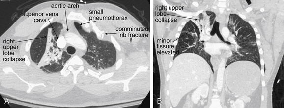
Figure 6-48 Lobar collapse with mediastinal shift resulting from volume loss.
CT with IV contrast viewed on lung windows to best illustrate lobar collapse. Same patient as Figure 6-47, in which his initial chest x-ray shows dramatic mediastinal shift to the right. This is due not to left-sided tension pneumothorax but to significant collapse of the right upper lobe. This results in volume loss on the right, and the mediastinum shifts right to occupy the resulting space. A, An axial slice through the upper chest shows a triangular cross section through the collapsed lung segment. The upper mediastinum has shifted right, and the aortic arch has a nearly right–left transverse orientation rather than an anterior–posterior orientation. A small left pneumothorax is visible as air (black) with no lung markings. B, A coronal view, in which the upper lobe collapse is again visible. The heart and trachea appear shifted right. The left lung does not show any evidence of pneumothorax in this view, though other images show a small pneumothorax. Certainly, a tension pneumothorax was not present and was not the cause of the mediastinal shift.
Diaphragm Injury
Injury to the diaphragm is discussed in detail in Chapter 10. On chest x-ray, the appearance depends on the degree of injury. In cases of overt herniation of intestinal contents into the chest, the appearance can be obvious. In subtle diaphragm tears without herniation of abdominal contents, no radiographic abnormalities may be seen on chest x-ray. Left diaphragmatic injuries are more common than right. In the case of left diaphragm rupture, the stomach (gastric air bubble) and loops of small bowel may be visible within the chest (Figures 6-49 through 6-55). If a nasogastric (NG) or an orogastric (OG) tube is present, it may be visible curled within the thorax (see Figure 6-49). Sometimes the appearance suggests only an elevated hemidiaphragm, but diaphragmatic injury must be suspected. When right diaphragm injury is present, the liver may appear to occupy an unusually cephalad position (see Figure 10-33). Overall, initial chest x-ray is thought to be only about 17% to 50% sensitive for detection of diaphragm rupture, and positive pressure ventilation is thought to reduce sensitivity, likely resulting from positive pressure pushing the affected diaphragm to a more normal caudad position.10-11
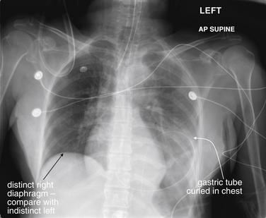
This 68-year-old female was ejected from a vehicle. Her chest x-ray shows several classic features of diaphragmatic rupture. The right diaphragm is normal in appearance, whereas the left diaphragm is not identified. The patient has an orogastric tube in place, which is coiled in the stomach—in the left lower to midthorax. This is consistent with herniation of the stomach through a diaphragmatic injury into the left thorax. Not specific to diaphragm rupture, the patient also has an indistinct aortic arch, concerning for traumatic aortic injury. The left thorax also appears denser than the right, possibly indicating hemothorax or diffuse pulmonary contusion. Compare with the patient’s CT in Figures 6-50 and 6-51.
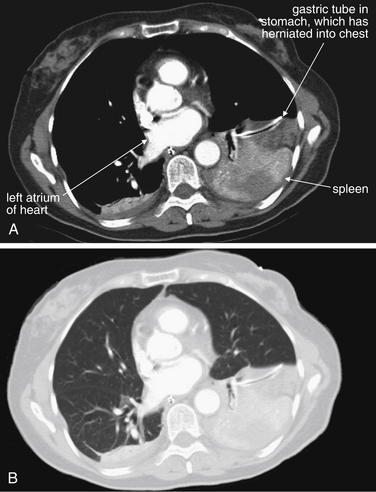
Figure 6-50 Diaphragm injury, CT with IV contrast.
CT images from the same patient as Figure 6-49 show the stomach and spleen to be present in the left chest, consistent with a diaphragm rupture. These two images show the same slice, at the level of the left atrium in the chest, on soft-tissue (A) and lung (B) windows. An orogastric tube is seen in the stomach. A portion of the spleen is also seen. On lung windows, no pneumothorax is identified.
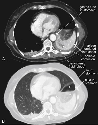
Figure 6-51 Diaphragm injury, CT.
CT images from the same patient as Figures 6-49 and 6-50. These two images show the same slice through the chest, on soft-tissue (A) and lung (B) windows. An orogastric tube is seen in the stomach, with an air–fluid level representing gastric contents. The spleen is also seen herniated into the chest with an area of parenchymal contusion. Perisplenic fluid is also seen. On lung windows, no pneumothorax is identified—the area of air is within the stomach.
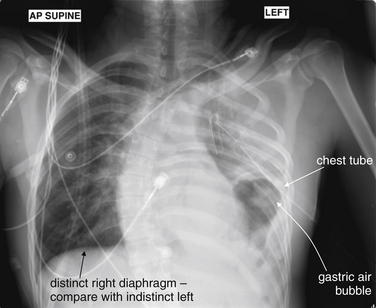
Figure 6-52 Diaphragmatic rupture.
This 21-year-old male was a rear-seat passenger in a head-on collision with dump truck. Two other passengers were killed at the scene. The patient was noted to have decreased oxygen saturations and no breath sounds. Needle decompression was performed by emergency medical services. This chest x-ray, taken in the emergency department after placement of a chest tube, shows features of diaphragmatic rupture. The normal curvature of the left diaphragm is not seen. The gastric air bubble is seen in the left chest. Note how closely the chest tube passes to the gastric air bubble, a reminder that care should always be taken to assess for solid organs in the chest when placing a chest tube. Not specific to diaphragm rupture, the patient also has opacification of the left hemithorax, which could represent pulmonary contusion or hemothorax on this supine film. In addition, herniation of abdominal contents into the chest can compress lung tissue, giving it this appearance. Compare this x-ray with the CT findings in Figures 6-53 through 6-55. Incidentally, the patient has a severe dextroscoliosis that is not a result of trauma.
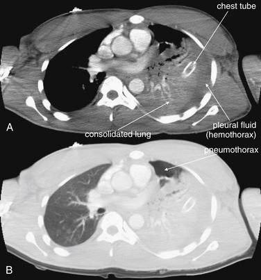
Figure 6-53 Diaphragmatic rupture, CT with IV contrast.
Figures 6-52 through 6-55 show images from the same case. A, Soft-tissue windows. B, The same slice viewed on lung windows. In these images near the lung apex, the thoracostomy tube is seen passing into consolidated lung parenchyma. From these images, it is not possible to determine whether this increased density of lung tissue represents contused lung from the original blunt injury or compressive atelectasis from the pressure exerted by herniated abdominal contents. A small anterior pneumothorax is seen on lung windows, despite the chest tube. Fluid density is seen surrounding the lung parenchyma on soft-tissue windows, representing hemothorax.
Figure 6-54 Diaphragmatic rupture.
These CT images are from the same patient as Figures 6-52, 6-53, and 6-55. A, Soft-tissue windows. B, The same slice viewed on lung windows. Here, the stomach is seen in the left chest adjacent to the heart. The air–fluid level represents gastric contents. Note how close to the stomach the thoracostomy tube passes—a reminder to consider diaphragm rupture and to perform a finger sweep when placing a thoracostomy tube for trauma.
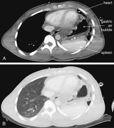
Figure 6-55 Diaphragmatic rupture, CT with IV contrast.
Figures 6-52 through 6-55 show images from the same case. A, Soft-tissue windows. B, The same slice viewed on lung windows. Here, the spleen and gastric air bubble are seen adjacent to the heart in the left chest. The right chest appears normal.
Mediastinal and Aortic Injuries
Life-threatening injury to the aorta and other mediastinal structures can occur with blunt or penetrating trauma. A variety of chest x-ray findings can provide clues to these injuries, as we describe later. Of paramount importance is understanding that an aortic injury may be present with a completely normal chest x-ray, albeit rarely. We discuss some controversies surrounding this rare event later in this chapter. Understanding the mechanisms behind aortic injuries can assist both in recognizing the radiographic appearance and in determining when chest x-ray abnormalities require further imaging. Because of the importance of this injury, we have included numerous example figures to illustrate the range of findings (Figures 6-56 through 6-108).
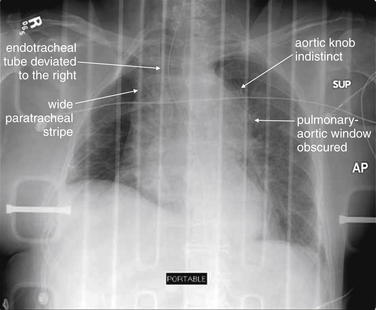
Figure 6-56 Thoracic aortic injury.
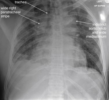
This patient has a classically abnormal chest x-ray for aortic injury. The mediastinum is wide, the aortic knob and aortopulmonary window are obscured, the trachea and endotracheal tube are deviated by mediastinal hematoma, and the right paratracheal stripe is extremely wide. The patient’s CT is shown in Figure 6-57.
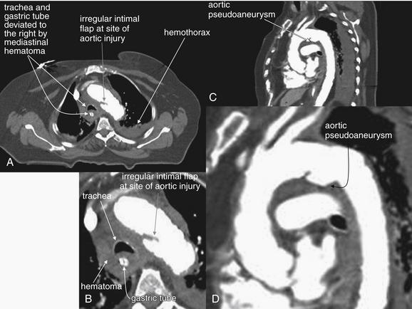
Figure 6-57 Thoracic aortic injury, CT with IV contrast, viewed with soft-tissue windows.
Same patient as Figure 6-56. A, Axial CT image. B, Close-up from A. C, Sagittal CT image.D, Close-up from C. The CT confirms aortic injury with mediastinal hematoma as the cause of the abnormal chest x-ray findings. The mediastinal hematoma surrounds the trachea and esophagus and deviates these to the patient’s right, at the same time creating a wide mediastinum. An aortic intimal injury and pseudoaneurysm are present at the classic location–the insertion site of the ligamentum arteriosum
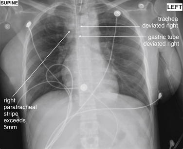
This 29-year-old female was struck by a car and was found unresponsive. Her mediastinum appears wide, and her trachea and orogastric tube are deviated to the right, relative to her thoracic spine. The aortic knob is not clearly seen, and the aortopulmonary window is not seen. These abnormalities can be the result of the mass effect of periaortic hematoma from aortic trauma. The radiology report stated that in this case they likely were resulting from the supine anterior–posterior technique, but CT confirmed aortic injury (Figure 6-59).
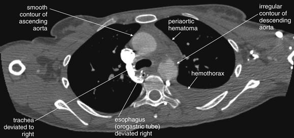
Figure 6-59 Aortic trauma, CT with IV contrast viewed with a variation on soft-tissue windows.
Same patient as Figure 6-58. This aortic injury is subtle but definite. Note the irregular contour of the descending aorta, compared with the smooth contour of the ascending aorta. Blood has escaped into the mediastinum, deviating the trachea and esophagus (marked by the orogastric tube) to the patient’s right. The periaortic hematoma also widens the mediastinum. A left hemothorax is present, possibly extending from the aorta. No active extravasation of injected contrast is seen. This is typical of survivors, because patients whose hemorrhage is not initially self-limited often die before reaching the emergency department.
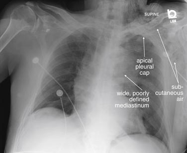
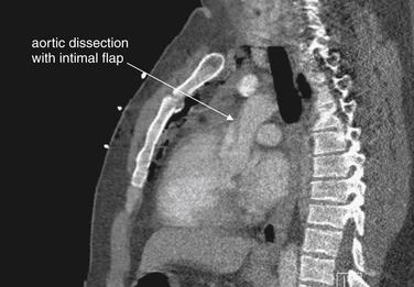
Figure 6-60 Aortic trauma or spontaneous aortic dissection?
This 89-year-old male was in a motor vehicle collision. His chest x-ray is concerning for aortic injury on several accounts. His mediastinum is widened, and the aorta is poorly defined. A left apical pleural cap, an indication of blood escaping from the superior mediastinum, is present (compare with the right lung apex, which appears normal). Although not specific for aortic injury, subcutaneous emphysema is seen in the patient’s left chest wall and neck. His CT is reviewed in Figure 6-61.
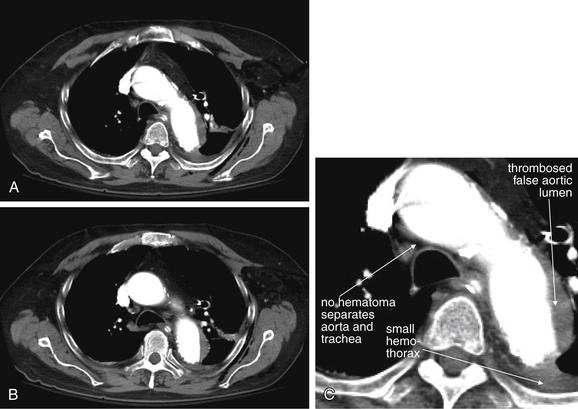
Figure 6-61 Aortic trauma or spontaneous aortic dissection?
Same patient as Figure 6-60. A, Axial CT slice through the aortic arch, viewed on soft-tissue windows. B, Axial slice slightly caudad to A, through the ascending and descending aorta. C, Close-up from A. The patient’s CT with IV contrast shows an abnormal aorta, but findings are more typical of a spontaneous aortic dissection than of aortic trauma. Did the patient have an aortic dissection leading to his car collision? We will never know—the patient was moribund on emergency department arrival. He certainly sustained trauma, with other injuries including splenic lacerations and rib fractures. Unlike the aortic traumatic injury in the previous case, there is no periaortic hematoma between the aorta and the trachea. Spontaneous aortic dissections often do not lead to blood loss from the aorta, because the injury involves the intima. The small hemothorax here may emanate from rib fractures.
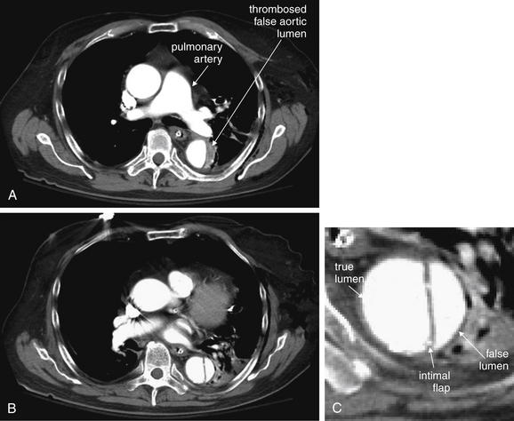
Figure 6-62 Aortic trauma or spontaneous aortic dissection?
Same patient as Figures 6-60 and 6-61. CT with IV contrast viewed with soft-tissue windows. The descending aorta has an intimal flap, more typical of spontaneous aortic dissection than of traumatic aortic injury. A, At the level of the pulmonary artery, the descending aorta shows thrombosis of the false lumen. B, Farther caudad, contrast is seen in both the true and the false lumen. C, Close-up from B.
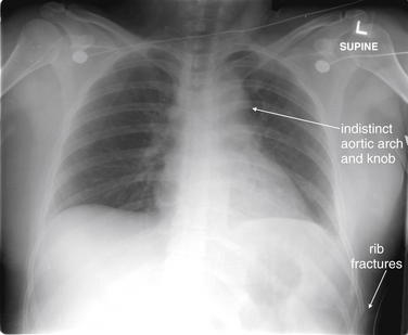
This 36-year-old female was a restrained passenger in a head-on collision. She had multiple evident injuries on emergency department arrival, including tibial plateau fractures and a pulseless right foot. Her chest x-ray shows an indistinct and somewhat broadened mediastinal contour, although the latter was attributed to the supine anterior–posterior technique. Rib fractures are also visible. Compare with the CT images in Figures 6-64 and 6-65.
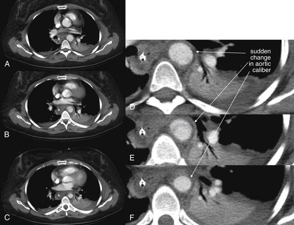
Figure 6-64 Aortic trauma, CT with IV contrast.
Same patient as Figures 6-63 and 6-65. A sudden change in aortic caliber is seen on these images, indicating a traumatic aortic injury. Figure 6-65 shows sagittal and three-dimensional reconstructions, demonstrating a pseudoaneurysm. A through C, Consecutive axial CT slices viewed on soft-tissue windows, progressing from cephalad to caudad. D through F, Close-ups from A, B, and C, respectively.
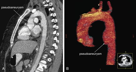
Figure 6-65 Aortic trauma, CT with IV contrast.
Same patient as Figures 6-63 and 6-64. A, Sagittal CT planar reconstruction, viewed on soft-tissue windows, depicting the aorta from its root through the arch and into the descending aorta. B, Three-dimensional reconstruction of the same region, with other thoracic structures digitally removed. The tiny image in the right lower corner of panel B is an axial cross-section inserted automatically by 3D software for orientation purposes. A, R, L, and P in that image indicate anterior, right, left, and posterior. These reformats are not necessary to make the diagnosis of traumatic aortic pseudoaneurysm but do help indicate the extent and assist with surgical planning. The patient underwent endovascular repair.
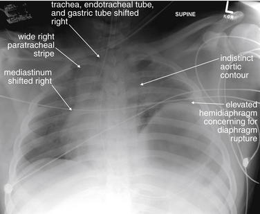
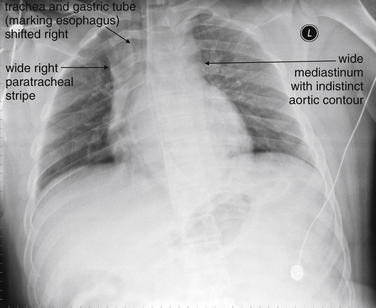
This 18-year-old man was involved in a severe motor vehicle collision. Among his many injuries were an open-book pelvis fracture and shock bowel. His chest x-ray shows an elevated left hemidiaphragm consistent with diaphragm rupture. His mediastinum is indistinct and shifted to the right, worrisome for aortic injury—which was confirmed on CT (Figures 6-67 and 6-68). Look carefully at the position of the endotracheal tube and gastric tube—both are shifted to the right. The right paratracheal stripe is also wide. These features are concerning for mediastinal hematoma, possibly from aortic injury. The patient developed multiorgan failure and died on hospital day 2.
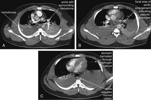
Figure 6-67 Aortic trauma, CT with IV contrast, axial images viewed with soft-tissue windows.
Same patient as Figures 6-66 and 6-68. Moving from cephalad (A) to caudad (C), note the change in aortic caliber. The enlarged region in B is a pseudoaneurysm. The patient has multiple other chest injuries, including a diaphragm rupture with the stomach in the left chest and a large right hemothorax.
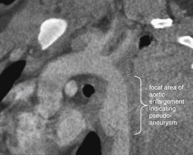
Figure 6-68 Aortic trauma, CT with IV contrast.
Figures 6-66 and 6-67 show images from the same case. This reconstruction in a parasagittal plane shows an area of traumatic pseudoaneurysmal dilatation. This can be recognized on the axial images (Figure 6-67) as a sudden change in aortic diameter.
This 20-year-old male struck a tree with his car and was hypotensive during emergency transport. His chest x-ray shows the now-familiar findings of a widened mediastinum, wide right paratracheal stripe, deviated trachea and gastric tube, indistinct aortic knob, and lack of the normal pulmonary artery window, consistent with traumatic aortic injury. See CT images, Figures 6-70 and 6-71, and aortogram, Figure 6-72.
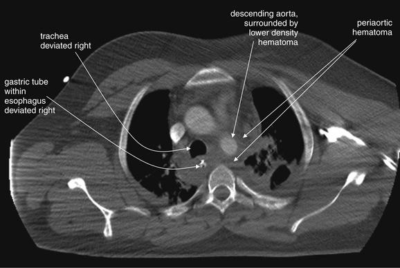
Figure 6-70 Aortic trauma, CT with IV contrast, axial image viewed with soft-tissue window.
Same patient as Figure 6-69. The aortic injury itself is not seen, but periaortic hematoma is present, deviating the trachea and gastric tube (within the esophagus) to the right, just as was seen on chest x-ray. Figure 6-71 shows the aortic injury.
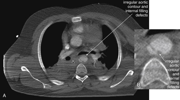
Figure 6-71 Aortic trauma, CT with IV contrast.
Figures 6-69 through 6-72 depict the same case. A, Axial CT slice viewed with soft-tissue windows. B, Close-up from A. More caudad, the descending aorta has an irregular contour and internal filling defects, indicating both an internal tear and a pseudoaneurysm formation. Compare with the angiogram from the same patient in Figure 6-72.
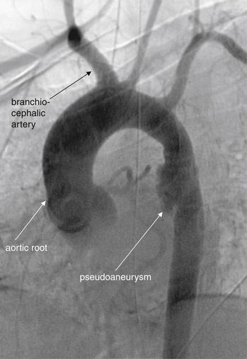
Figures 6-69 through 6-72 show images from the same case. The patient underwent an aortogram, confirming an aortic pseudoaneurysm. Note the similarity to the appearance on CT reconstructions from the prior cases. No active extravasation of contrast is seen. The patient’s injury was repaired using endovascular stents.
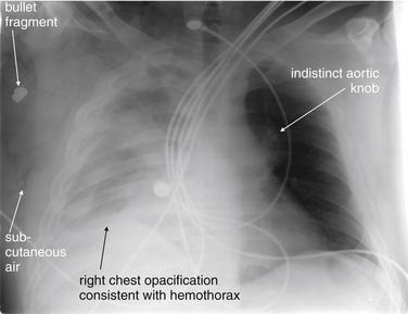
A 26-year-old male was shot just left of the sternum. The bullet crossed the midline, coming to rest in the right axilla. This chest x-ray demonstrates complete opacification of the right chest, consistent with a large hemothorax, as well as possible underlying pulmonary contusion. Subcutaneous air is visible in the right chest wall. The aortic knob is not clearly defined, raising the question of a mediastinal injury. The patient underwent CT (Figures 6-74 and 6-75).
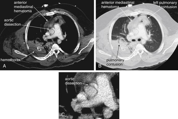
Figure 6-74 Aortic trauma CT with IV contrast.
Figures 6-73 through 6-76 depict other images from the same case. A, Axial CT slice, viewed with soft-tissue windows. B, The same slice, viewed with lung windows. C, Close-up from A. The bullet has tracked across the anterior mediastinum, resulting in a left anterior pulmonary contusion, an anterior mediastinal hematoma, and apparent dissection of the ascending aorta with an intimal flap. The left pulmonary contusion, anterior mediastinal hematoma, and right posterior pulmonary contusion all contribute to the appearance of the wide mediastinum and obscured aortic knob on chest x-ray. The patient underwent thoracotomy and intraoperative ultrasound, in which the intimal flap seen on CT was thought to represent artifact. No aortic repair was performed. The ascending aorta is subject to motion artifacts on CT that can simulate aortic dissection. Electrocardiogram-gated CT can eliminate this motion artifact to allow more accurate evaluation.
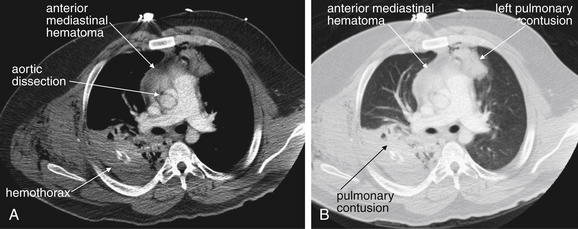
Figure 6-75 Aortic trauma, CT with IV contrast.
Same patient as Figures 6-73, 6-74, and 6-76. A, Axial CT slice, viewed with soft-tissue windows. B, The same slice, viewed with lung windows. Note how different window settings reveal different information from the same anatomic region.
This sagittal CT reconstruction from the same patient as Figures 6-73 through 6-75 also appears to show an intimal flap of the ascending aorta. Intraoperative ultrasound was felt to be negative for dissection. Motion artifact at the aortic root can cause false positive findings. ECG gating (discussed in Chapter 8) can eliminate this artifact.
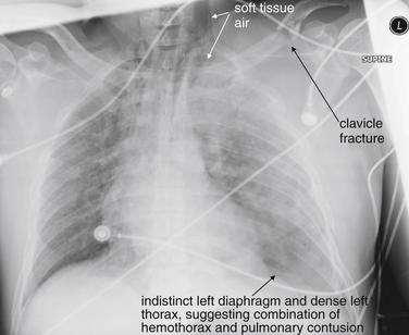
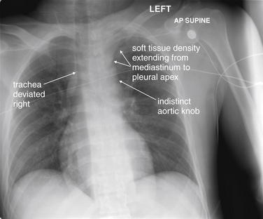
This 34-year-old male was riding a motorcycle when he was struck by an oncoming car. His chest x-ray demonstrates multiple abnormalities, including a left clavicle fracture and left first rib fracture, and increased density of both hemithoraces, suggesting possible pulmonary contusion. The left diaphragm is not clearly seen, which may indicate a layering hemothorax on this supine chest x-ray. Diaphragm rupture can also result in an indistinct diaphragm. Air is visible, tracking in the left neck and outlining the superior mediastinum. The heart and mediastinum appear slightly deviated to the right side. The aortic knob is not clearly seen. The patient’s chest CT is reviewed in Figures 6-78 and 6-79.
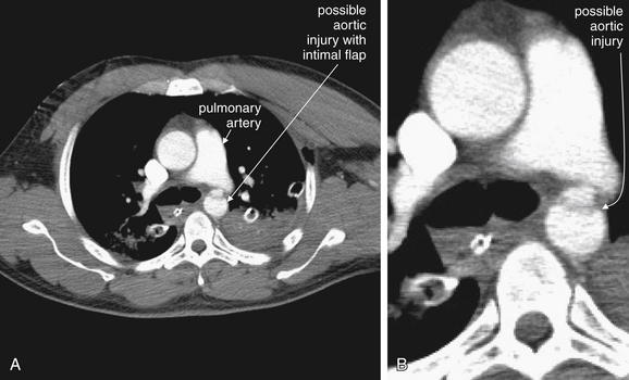
Figures 6-77 through 6-80 depict the same case. A, Axial CT slice, viewed with soft-tissue windows. B, Close-up from A. On the patient’s initial CT with IV contrast, only a single slice revealed a possible aortic injury. A transverse filling defect suggested an intimal flap where the aorta passes the pulmonary artery—the location of the ligamentum arteriosum. Coincidence? This was suspected to be artifact, and repeat CT with finer cuts was performed (Figure 6-79).
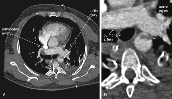
A, Axial CT slice, viewed with soft-tissue windows. B, Close-up from A. Repeat CT showed the same appearance of a transverse filling defect at precisely the same level as in Figure 6-78, proving an aortic injury. This injury is at the level of the ligamentum arteriosum, which once connected the pulmonary artery and aorta. Coronal and sagittal reconstructions are shown in Figure 6-80.
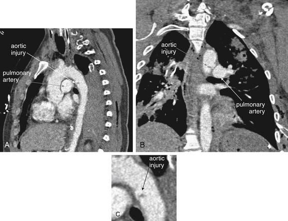
Figure 6-80 Aortic trauma, CT with IV contrast.
Figures 6-77 through 6-80 depict the same case. A, Sagittal CT reconstruction, viewed with soft-tissue windows. B, Coronal CT reconstruction. C, Close-up from A. These reconstructions confirm an aortic injury at the level of the ligamentum arteriosum, which once connected the pulmonary artery and aorta. Endovascular repair was performed.
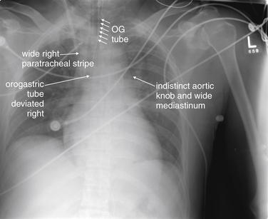
This 46-year-old male was found unconscious and hypothermic in a car that had crashed at an unknown time. His core temperature was 31°C. The patient was found in the passenger seat and was unrestrained. His chest x-ray shows a wide mediastinum with no distinct aortic knob. The right paratracheal stripe is wide. These findings could be the result of a mediastinal hematoma from aortic injury. CT was performed (Figure 6-82 and 6-83), followed by aortography (Figure 6-84).
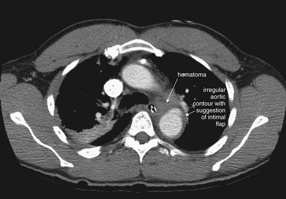
A CT with IV contrast (axial image, soft-tissue window) from the same patient as Figure 6-81 demonstrates an irregular aortic contour and a small amount of periaortic hematoma just anterior to the aorta. Figure 6-83 shows two slightly oblique reconstructions that further define this injury.
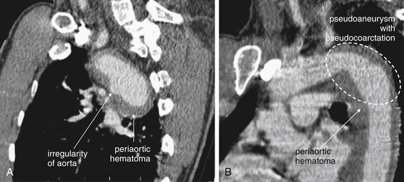
Figure 6-83 Aortic trauma, CT with IV contrast.
Figures 6-81 through 6-84 explore the same case. A, Sagittal CT image, soft-tissue window. reconstruction from the same patient demonstrates an irregular aortic contour and a small amount of periaortic hematoma (dark gray, soft-tissue density on these soft-tissue windows) just anterior to the aorta. B, The area of injury begins with a narrowed region (pseudocoarctation) and progresses into a dilated area (pseudoaneurysm). Aortogram was performed (Figure 6-84).
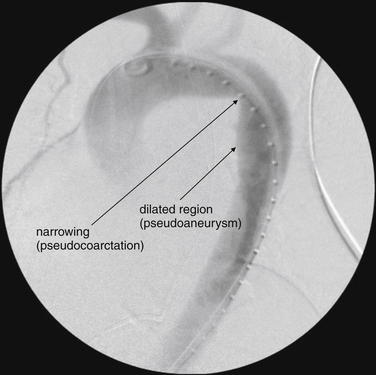
Figures 6-81 through 6-84 explore the same case. Aortogram from the patient demonstrates the same configuration of pseudocoarctation and pseudoaneurysm. An aortic stent graft was placed.
This 29-year-old male was an unrestrained driver in a high-speed motor vehicle collision. His injuries included a hip dislocation, femur fracture, and open tibia fracture.
The patient’s chest x-ray shows deviation of the trachea to the right, which we have seen can be the effect of a mediastinal hematoma from aortic injury. The mediastinum does not appear especially wide, but the aortic knob is indistinct. In addition, there is suggestion of an apical pleural cap. Some of these features may be a result of supine position and the patient’s rotation to the right. The patient’s chest x-ray after intubation supports the concern for mediastinal hematoma (Figure 6-86).
Same patient as Figure 6-85. The patient has now been intubated, and an orogastric tube has been placed. The orogastric tube is also deviated to the right, suggesting a mediastinal hematoma. The right paratracheal stripe is also wide. The patient’s CT scan is reviewed in Figures 6-87 and 6-88.
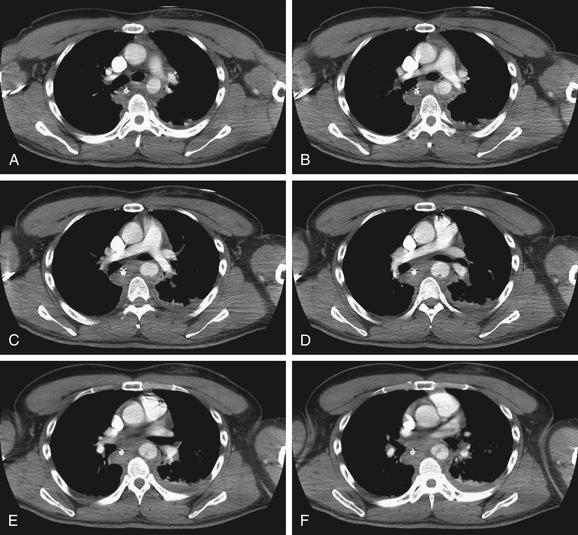
Figure 6-87 Aortic trauma, CT with IV contrast.
Same patient as in Figures 6-85 and 6-86. Consecutive axial CT images viewed with soft-tissue windows. A through H descend from cephalad to caudad. In B, a defect resembling an intimal flap is seen. C through F, An irregularity projects into the lumen from the posterior aortic wall.
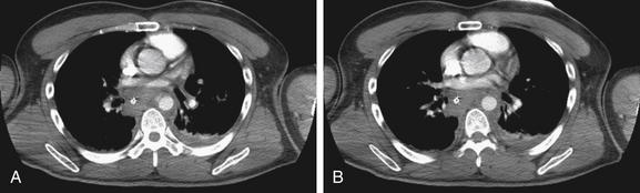
Same patient as in Figures 6-85 through 6-87. A, a defect resembling an intimal flap is seen. B, the aorta resumes its normal size and smooth internal contour.
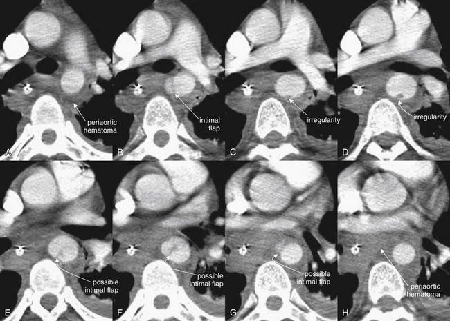
Figure 6-89 Aortic trauma, CT with IV contrast.
Figures 6-85 through 6-89 explore the same case. A through H here are close-ups from panels A through H in Figures 6-87 and 6-88. They are taken from consecutive axial CT images through the region of the descending thoracic aorta, viewed with soft-tissue windows.A to H descend from cephalad to caudad. Periaortic hematoma and irregularities of the descending aorta are seen.
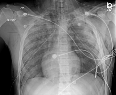
This 17-year-old male was found outside of his vehicle at 4:15 AM. In the emergency department, he was unresponsive, with fixed and dilated pupils and priapism. The patient is intubated and bilateral chest tubes have been placed. Both lungs show increased density, suggesting pulmonary contusion. The gastric tube is deviated to the right, and the aortic knob is indistinct. A black line surrounds the heart, suggesting pneumomediastinum. Fractures of the first and second ribs were also noted, although they are hard to see in this image. CT was performed (Figures 6-91, 6-92).
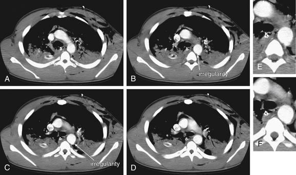
Figure 6-91 Aortic trauma, CT with IV contrast.
A through D, Consecutive axial CT slices through the thorax, viewed with soft-tissue windows. A through D descend from cephalad to caudad. E, Close-up from B. F, Close-up from C. A CT from the same patient as Figure 6-90 shows a focal defect in the posterior wall of the descending aorta, visible only on two consecutive slices. This is a traumatic pseudoaneurysm. Figure 6-92 shows this in sagittal reconstructions.
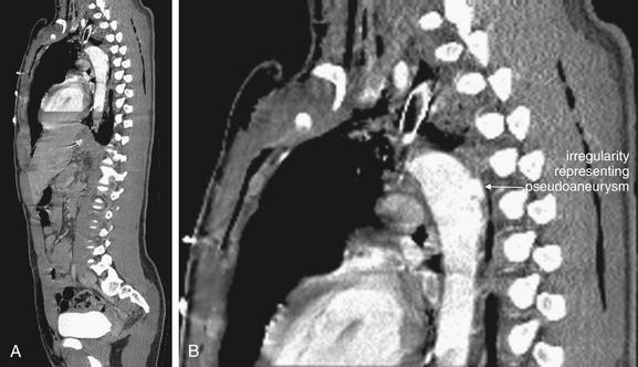
Figure 6-92 Aortic trauma, CT with IV contrast.
A, Sagittal CT reconstruction from the same patient as in Figures 6-90 and 6-91 shows a focal defect in the posterior wall of the descending aorta. This is a traumatic pseudoaneurysm. B, Close-up from A. Both images are viewed with soft-tissue windows.
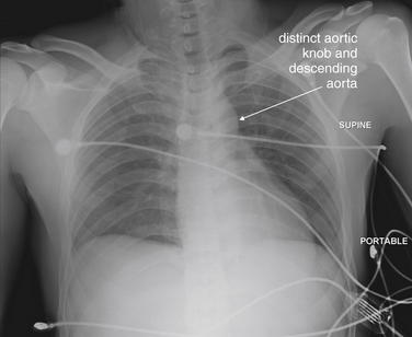
This 30-year-old male fell from a tower while doing electrical work—an estimated 20 to 50 feet. He complained of back and abdominal pain, as well as dyspnea. Notably, he had no palpable pulses in his lower extremities. His chest x-ray was interpreted as normal—the trachea is not deviated, the mediastinum is not wide for a supine x-ray, and the aortic knob and descending aorta are clearly visible. His CT is shown in Figures 6-94 through 6-98.
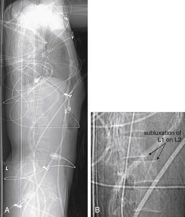
Figure 6-94 Aortic trauma: Abdominal aorta.
A, The patient’s scout CT image is telling—a significant step-off is visible at the L1-2 level. Remember that the abdominal aorta lies just anterior to the spinal column at this level. B, Close-up from A. Figure 6-95 examines axial CT slices.
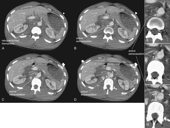
Figure 6-95 Aortic trauma: Abdominal aorta, CT with IV contrast.
Figures 6-93 through 6-98 depict the same case. A, The abdominal aorta appears nearly normal, but already a very large bilateral retroperitoneal hematoma is visible (soft-tissue density, gray on these soft-tissue windows), extending posterior to both kidneys. This abnormality is seen in all of the slices shown but labeled only in A. B to D, A blush of contrast (white) indicating active extravasation of injected contrast is visible adjacent to the aorta. E, F, and G at right are close-ups from B, C, and D, respectively.
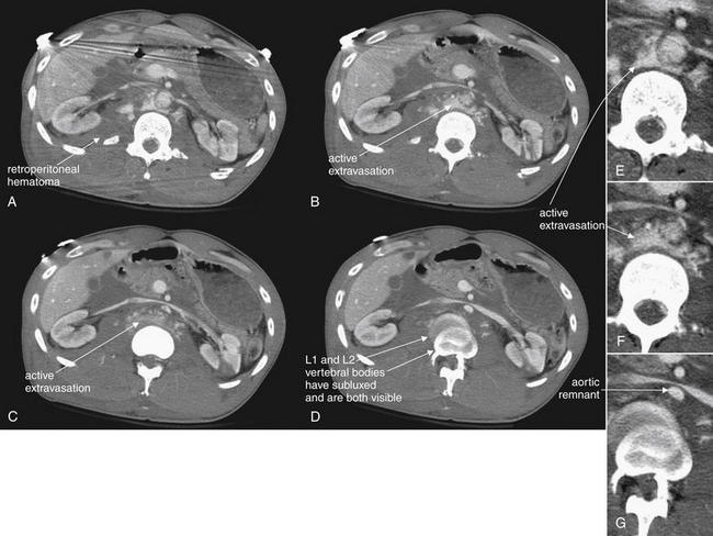
Figure 6-96 Aortic trauma: Abdominal aorta.
Figures 6-93 through 6-98 depict the same case. Continuation of Figure 6-95. A, The abdominal aorta is identifiable, with active extravasation and a large retroperitoneal hematoma. Blood that had collected before CT appears soft-tissue density (gray), whereas actively extravasating blood is mixed with contrast and appears white. By B to D, the aorta is a tiny remnant vessel. D, The double image of the vertebral body is not artifact—this is the level of the subluxation of L1 on L2, and both vertebrae are seen. E, Close-up from A. F, Close-up from B. G, Close-up from D.
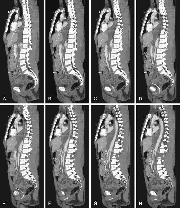
Figure 6-97 Aortic trauma: Abdominal aorta, CT with IV contrast.
Figures 6-93 through 6-98 depict the same case. A to H, Sagittal CT reconstructions reveal both the spinal subluxation and the major aortic injury. Remarkably, the patient survived and was able to walk with a rolling walker despite some spinal cord injury.
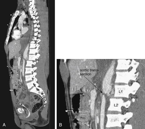
Figure 6-98 Aortic trauma: Abdominal aorta, CT with IV contrast.
Other images from the same patient are shown in Figures 6-93 through 6-97. A, Sagittal reconstruction viewed with soft-tissue windows reveals both the spinal subluxation (L1 on L2) and the major aortic injury. The abdominal aorta reconstitutes below the level of transection but has a smaller diameter. B, Close-up from A. Remarkably, the patient survived and was able to walk with a rolling walker despite some spinal cord injury.
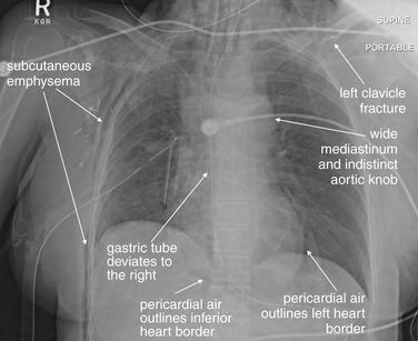
This 54-year-old female was an unrestrained passenger in a car that struck a tree. Her chest x-ray shows a wide mediastinum with deviation of the trachea. The gastric tube, which appears nearly midline at the top of the x-ray, deviates to the right upon entering the mediastinum, suggesting possible mediastinal hematoma. The aortic knob is not well defined. These findings could indicate aortic injury. Other trauma findings in this patient include a left clavicle fracture, multiple right rib fractures, a right chest tube with subcutaneous air in the right chest wall, and pneumopericardium. This last finding is indicated by the visible inferior and left heart borders. The inferior border of the heart is not normally seen, because it is fluid density and lies in direct contact with the diaphragm, also fluid density. In this case, air in the pericardial sac provides contrast. Compare with the CT (Figure 6-100).
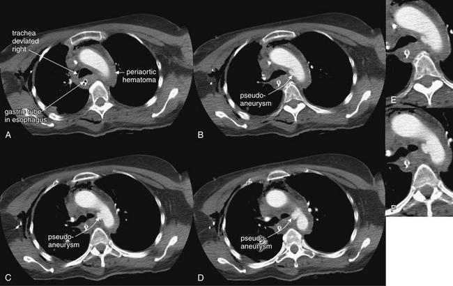
Figure 6-100 Aortic trauma, CT with IV contrast.
Same patient as in Figure 6-99. Consecutive axial CT images viewed with soft-tissue windows, descending from A through H. The images show periaortic hematoma (soft-tissue density, gray) surrounding the aortic arch and deviating the trachea and esophagus to the patient’s right. A focal defect in the distal aortic arch is visible—a traumatic pseudoaneurysm. E, Close-up from B. F, Close-up from C. Figure continues in Figure 6-101.
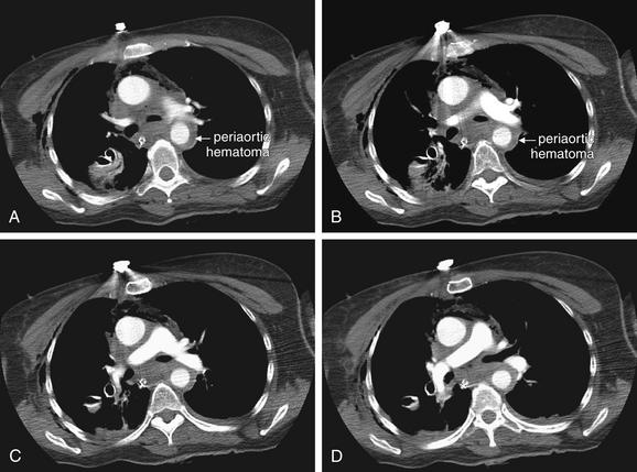
Additional images for the same patient are shown in Figures 6-99 through 6-104. A-D, The circumferential periaortic hematoma extends distally around the uninjured portion of the descending aorta. This hematoma continues to deviate the esophagus and gastric tube, as was seen on chest x-ray.
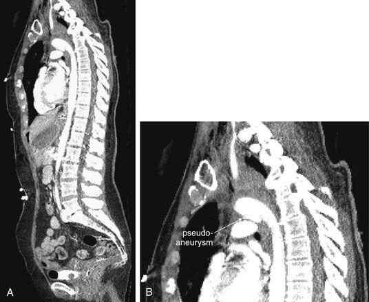
Figure 6-102 Aortic trauma, CT with IV contrast.
Additional images for the same patient are shown in Figures 6-99 through 6-104. A, Sagittal CT reconstruction using soft-tissue windows shows the pseudoaneurysm as an irregularity on the inferior aspect of the distal aortic arch. B, Close-up from A.
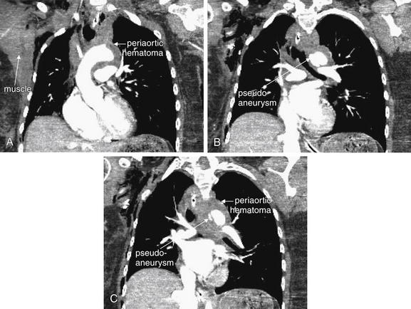
Figure 6-103 Aortic trauma, CT with IV contrast.
Additional images for the same patient are shown in Figures 6-99 through 6-104. These coronal images show the periaortic hematoma and traumatic pseudoaneurysm. A to C move from anterior to posterior. B, C, The aorta does not have the normal smooth and rounded contour. In all three images, circumferential periaortic hematoma is present. On these soft-tissue windows, hematoma is gray, similar to skeletal muscle.
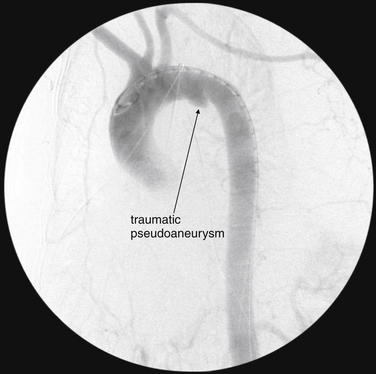
Additional images for the same patient are shown in Figures 6-99 through 6-104. This aortogram demonstrates the pseudoaneurysm. Although aortography has been the historical gold standard for this diagnosis, CT can give more three-dimensional information. This pseudoaneurysm appears relatively small in this image, because a portion of it extends posterior to the opacified aortic arch and is hidden in this projection. During aortography, usually several projections are obtained from different angles to overcome this limitation.
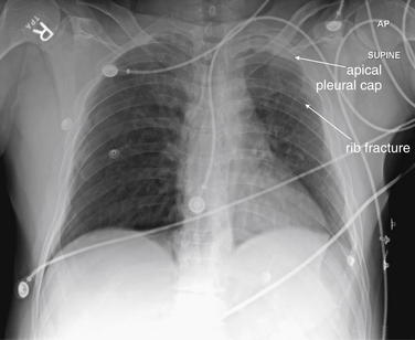
Figure 6-105 Apical pleural cap.
An apical pleural cap is a finding associated with traumatic aortic injury. It is a soft-tissue (fluid) density at the lung apex, which can represent blood tracking out of the superior mediastinum and above the pleural surface of the lung apex.
This 48-year-old male struck a car on his motorcycle. His chest x-ray shows an apical pleural cap on the left—compare with the normal right apex. He also has left-sided rib fractures. CT did not show an aortic injury; an apical pleural cap is a nonspecific finding, though it warrants further study with CT in the setting of significant trauma.
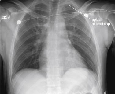
Figure 6-106 Apical pleural cap.
This 25-year-old male rolled his car and was transported by emergency medical services. His chest x-ray shows a possible apical pleural cap, as well as a poorly defined aortic knob. Follow-up CT did not show an aortic injury.
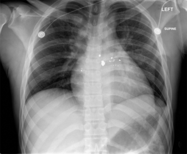
Figure 6-107 Gunshot wound to back with bullet adjacent to aorta.
This 22-year-old male was shot in the posterior thorax just left of midline. He complained of back and abdominal pain. His supine chest x-ray shows radiopaque bullet fragments left of the thoracic spine. The x-ray is otherwise unremarkable. CT was performed to localize the bullet (Figure 6-108).
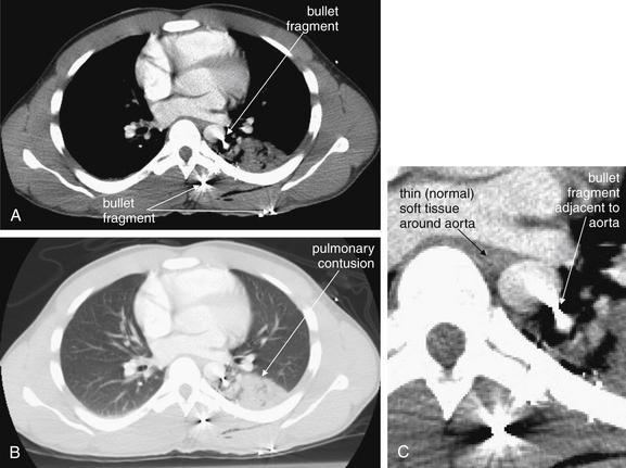
Figure 6-108 Gunshot wound to back with bullet adjacent to aorta, CT with IV contrast.
A, Axial CT slice viewed with soft-tissue windows. B, The same slice, viewed with lung windows. C, Close-up from A. This CT from the same patient as in Figure 6-107 shows three bullet fragments, marked by metallic streak artifact. One lies immediately subcutaneously. The second is within paraspinal muscle exterior to the bony thorax. The third lies immediately adjacent to the aorta. Streak artifact makes complete evaluation of the aorta impossible, but no significant hematoma surrounds the aorta. The adjacent lung shows contusion but no hemopneumothorax.
This patient was observed briefly and did not undergo further imaging to evaluate the aorta. However, aortography could have been used to assess this injury. Unlike CT, aortography is not subject to metallic streak artifact and could have identified irregularity of the aorta near the bullet fragment.
Consider for a moment the events occurring with aortic injury. Aortic injury from blunt trauma is a deceleration injury, requiring significant energy to be imparted into the chest. Because the kinetic energy of an object is determined by (1/2)mv2 (where m = mass and v = velocity), the dominant variable in determining the energy involved in trauma is usually velocity. Exceptions can occur when an extremely massive object is involved, but generally the energy transfer from blunt chest trauma with objects such as fists or baseball bats is not sufficient to result in aortic injury, as both the mass and the velocity are low. Thus a mediastinal abnormality on chest x-ray in a patient who had been punched in the chest or who has fallen from a standing position to the ground is unlikely to represent a mediastinal injury, even if injuries such as rib fractures are present. As a consequence, incidental x-ray findings that hint at mediastinal pathology may not need to be pursued acutely in this setting.
In higher-velocity (higher energy) blunt trauma, the thorax is brought to a rapid stop by a collision with a static object. The aorta continues to move forward in the thorax until it is halted by reaching the end of its tether, the ligamentum arteriosum—the remnant of the embryonic ductus arteriosus. This structure attaches to the inferior surface of the aorta at a point near the origin of the descending aorta or distal aortic arch. The ligamentum arteriosum is attached inferiorly to the pulmonary artery and restricts anterior aortic motion. An aortic tear most often occurs at this location in blunt trauma, although other injury locations are possible. As you review the CT and aortography images in this chapter, note this consistent location of aortic injuries.
Some aortic tears are full thickness, resulting in rapid exsanguination and death at the scene of injury. In other cases, the tear is either partial thickness (involving the aortic intima and muscularis but leaving the adventitia intact) or full thickness but limited by the formation of a mediastinal hematoma, allowing survival and transport to the emergency department. In these patients, the aortic contour may appear abnormal, and the silhouette on the AP or PA chest x-ray may be altered by the presence of mediastinal hematoma. Several classic chest x-ray findings can result from this mediastinal hematoma (Table 6-4) (see Figures 6-56, 6-58, 6-60, 6-63, 6-66, 6-69, 6-73, 6-77, 6-81, 6-85, 6-86, 6-90, 6-93, 6-99, 6-105, and 6-107):
TABLE 6-4 Chest X-ray Findings Suggesting Aortic Injury
| Wide mediastinum | The mediastinum may appear wider than normal. An upper limit of 8 cm (measured from the left aortic arch to the right mediastinal margin) has been described, although lesser degrees of widening can occur with small mediastinal hematomas. Unfortunately, this finding is only about 90% sensitive and 10% specific. The supine AP chest x-ray often obtained following blunt trauma can simulate pathologic mediastinal widening from aortic injury. |
| Indistinct aortic knob | The aortic knob may lose its distinct and rounded appearance due to hematoma surrounding it. The margins may appear indistinct or irregular. |
| Loss of aortopulmonary window | A normal lucent region, the aortopulmonary window (formed by the intersection of the normal left pulmonary artery and the descending aorta) may be obscured by mediastinal hematoma. |
| Wide right paratracheal stripe | The right paratracheal stripe (PTS), which is normally a thin water-density stripe between the air column of the trachea and the adjacent lung on frontal projection chest x-ray, may become widened by the presence of mediastinal hematoma. The upper limit of normal is 4 mm, with 5 mm reliably being abnormal. In one study, no patient with PTS <5 mm had an aortic injury, while 22.9% of those with PTS ≥5 mm had a vascular injury. |
| Displaced left paraspinous line | The left paraspinous line may be displaced by mediastinal blood. |
| Apical pleural cap | |
| Pleural effusion | |
| Displacement of mediastinal structures | Other structures passing through the mediastinum may be distorted or displaced by mediastinal hematoma. These include normal anatomic structures and medical devices commonly seen in trauma patients: |
| Skeletal injuries |
From American College of Radiology. ACR appropriateness criteria: Blunt chest trauma—Suspected aortic injury. (Accessed at http://www.acr.org/SecondaryMainMenuCategories/quality_safety/app_criteria/pdf/Vascular/BluntChestTraumaSuspectedAorticInjuryDoc6.aspx.); Lee RB, Bass SM, Morris JA Jr, et al. Three or more rib fractures as an indicator for transfer to a level I trauma center: A population-based study. J Trauma 30(6):689-694, 1990; Lee J, Harris JH Jr, Duke JH Jr, et al. Noncorrelation between thoracic skeletal injuries and acute traumatic aortic tear. J Trauma 43(3):400-404, 1997; Savoca CJ, Austin JH, Goldberg HI. The right paratracheal stripe. Radiology 122(2):295-301, 1977; Savoca CJ, Brasch RC, Gooding CA, et al. The right paratracheal stripe in children. Pediatr Radiol 6(4):203-207, 1978; Ungar TC, Wolf SJ, Haukoos JS, et al. Derivation of a clinical decision rule to exclude thoracic aortic imaging in patients with blunt chest trauma after motor vehicle collisions. J Trauma 61(5):1150-1155, 2006; Woodring JH, Pulmano CM, Stevens RK. The right paratracheal stripe in blunt chest trauma. Radiology 143(3):605-608, 1982.
In effect, most of the chest x-ray findings of aortic injury are secondary signs of mediastinal hematoma, which can be present in the absence of aortic injury or absent in the presence of aortic injury.12,19 Because the size of the hematoma and the degree of aortic injury vary from patient to patient, the severity and prominence of these findings varies. Some patients with aortic injuries have all of these findings; others have only a few. Rarely, the aortic injury is so subtle that the chest x-ray, which gives only the silhouette of superimposed mediastinal structures, appears normal. More commonly, the chest x-ray suggests possible aortic injury when none is present. For example, mediastinal widening may occur resulting from supine position, preexisting and intact thoracic aortic aneurysm, mediastinal lymphadenopathy unrelated to trauma, a tortuous course of the aorta, goiter extending to the mediastinum, or venous hematomas from sources other than the aorta, including spinal injuries with prevertebral hematomas. For this reason, an abnormal chest x-ray with findings of mediastinal hematoma is not specific for aortic injury. Overall, chest x-ray is normal in only about 7% of traumatic aortic injuries,20 and the negative predictive value of chest x-ray has been reported as 95%, due in large part to the rarity of aortic injury.21
Direct evidence of aortic injury may also be seen on chest x-ray: a change in aortic contour may be a direct result of the aortic tear and potential aortic pseudoaneurysm formation. Table 6-5 shows the frequency of various chest x-ray findings in cases of aortic injury.
TABLE 6-5 Abnormal Chest X-ray Findings in Traumatic Aortic Injury
| Finding | Frequency in Cases of Aortic Injury |
|---|---|
| Wide mediastinum | 85% |
| Indistinct aortic knob | 24% |
| Apical pleural cap | 19% |
| Left pleural effusion | 19% |
| First and/or second rib fracture | 13% |
| Tracheal deviation | 12% |
| NG tube deviation | 11% |
From Fabian TC, Richardson JD, Croce MA, et al. Prospective study of blunt aortic injury: Multicenter Trial of the American Association for the Surgery of Trauma. J Trauma 42(3):374-380, 1997; discussion 380-383.
Pneumomediastinum and Pneumopericardium
Pneumomediastinum and pneumopericardium can be seen on chest x-ray in blunt and penetrating trauma, and they occur periodically without any history of trauma, sometimes following forceful vomiting or cough. The significance of these findings varies substantially with the history and clinical context. For example, following vomiting, pneumomediastinum is concerning for esophageal rupture with threat of consequent mediastinitis, whereas the same chest x-ray finding following cough usually is due to a microscopic leak of air from the lung or airway and results in a benign clinical course without any intervention. In the setting of blunt trauma, pneumomediastinum and pneumopericardium should raise suspicion of accompanying pneumothorax or tracheobronchial injury. The chest x-ray should be scrutinized for evidence of these, and depending on the degree of suspicion, additional imaging may be warranted—for evaluation of the source of the air, not for specific treatment of the pneumopericardium or pneumomediastinum. In penetrating chest trauma, these findings again can suggest injury to the lung or tracheobronchial tree, but an esophageal injury should also be considered as a potential source.
Air in the pericardium or mediastinum appears black on chest x-ray (Figures 6-109 through 6-113). The finding can be extremely subtle, but the cardiac silhouette should be scrutinized on the frontal projection (and the lateral view, if available) for a thin black line on either the interior of or the exterior of the pericardium. Normally, the pericardium is in contact with a thin lubricating layer of pericardial fluid that in turn is in contact with the epicardial surface of the heart. Because these all share the same density, the internal surface of the pericardium is not normally visible. When air is present within the pericardium, it provides contrast between the pericardium and the cardiac surface, allowing the inner pericardial surface to be seen. An additional finding sometimes seen is called the continuous diaphragm sign, which occurs when air is visible along the caudad surface of the heart (see Chapter 5). Normally, the cephalad surface of each hemidiaphragm is visible resulting from low-density lung abutting this surface. The central surfaces of the diaphragm are not normally visible, as the heart and pericardium abut the diaphragm centrally and share its density. Therefore the normal appearance of the diaphragm when traced from the patient’s right to left is discontinuous, with the upper surface becoming invisible at the center of the chest and then reappearing to the left of the heart. When air is present within the pericardium, the superior diaphragmatic surface is visible as an apparently continuous line from the patient’s right to left. Air in the upper mediastinum may outline structures extending into the neck, so fine linear lucencies should be sought outlining the trachea, great vessels, and muscles extending into the cervical region (see Figure 6-109).
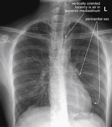
Figure 6-109 Pneumomediastinum.
This 18-year-old college student developed chest pain while lying in bed. He had no history of trauma, cough, or vomiting but had played basketball earlier in the day. His chest x-ray shows the typical subtle findings of pneumomediastinum. The white line paralleling the left heart border is the pericardium—the lucent region between the pericardium and the left heart border is air within the pericardial sac. Some vertically oriented lucent areas are seen in the upper mediastinum as well. The inferior border of the heart is not outlined with air in this case, although air may be seen in that location. What was the source of the air? No pneumothorax is seen, but perhaps the patient performed the Valsalva maneuver during his basketball game and forced air from the respiratory tree into the mediastinum. Compare with his lateral chest x-ray (Figures 6-110 and 6-111). His CT images are reviewed in Figures 6-112 and 6-113, although arguably CT was unnecessary. The patient recovered uneventfully.
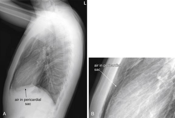
Figure 6-110 Pneumomediastinum.
Same patient as in Figures 6-109 and 6-111. A, The lateral chest x-ray shows some subtle findings of pneumomediastinum. B, Close-up from A. A faint black line (air) marks the anterior surface of the heart. In addition, normally no interface can be seen between the inferior heart border and the diaphragm, because they share the same x-ray density. However, a lucent line marks the inferior heart border here, indicating air in the pericardium.
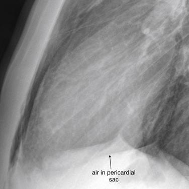
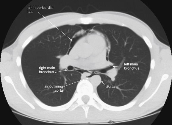
Figure 6-112 Pneumomediastinum.
Figures 6-109 through 6-113 explore this case with x-ray and CT. This CT image (lung windows) high in the mediastinum just inferior to the carina shows air outlining the heart anteriorly, as well as air posterior to the heart, including outlining the aorta.
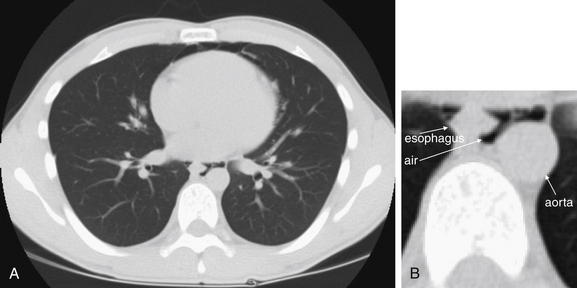
Figure 6-113 Pneumomediastinum.
Same patient as in Figures 6-109 through 6-112. Figures 6-109 through 6-113 explore this case with x-ray and CT. A, This computed tomography image (lung windows) lower in the mediastinum shows air (black) outlining the aorta and esophagus—areas where no air should be found. B, Close-up from A.
Pericardial Effusion and Hemopericardium
On chest x-ray, water, blood, other fluids, and soft tissues such as the myocardium share the same density. Two structures in direct contact and sharing the same density cannot be distinguished from one another on chest x-ray (see Chapter 5 for more discussion of the silhouette sign). Consider, for example, the normal radiographic appearance of the heart; the solid (soft tissue) myocardium cannot be distinguished from the liquid blood within its chambers. Fluid within the pericardium outside of the heart also cannot be distinguished from the myocardium. With a moderate to large pericardial effusion, the appearance on a supine AP chest x-ray usually demonstrates an enlarged cardiac silhouette—though this appearance may be simulated even in the absence of a pericardial effusion resulting from the supine AP technique (as described earlier in this chapter; see Figure 6-1). Cardiomegaly would be expected to have a similar appearance and cannot be formally distinguished with chest x-ray. Ultrasound and CT can readily differentiate the two conditions. If an upright chest x-ray is obtained, a pericardial effusion may take on the classic “water bottle” shape resulting from pooling of fluid in the dependent pericardium (see Chapter 5). However, this appearance is most prominent when a large pericardial effusion is present. In many cases of blunt and penetrating trauma, the amount of pericardial blood is less significant than in more slowly accumulating pericardial effusions from uremia or malignancy, and the radiographic appearance may be subtler with mild apparent cardiomegaly. Even a small quantity of rapidly accumulated pericardial fluid can result in hemodynamic compromise, because the pericardium itself has not been stretched over time, as is sometimes seen in nontraumatic pericardial effusions. Consequently, even subtle traumatic pericardial effusions suspected by chest x-ray or confirmed by ultrasound or CT may be clinically significant.
Pneumoperitoneum
Pneumoperitoneum is infrequently seen in blunt trauma but can be seen with either blunt or penetrating trauma. Stab wounds and gunshot wounds to the chest can traverse the diaphragm and injure bowel. Sometimes air from thoracic sources such as pneumothorax can cross the diaphragm into the abdomen, resulting in pneumoperitoneum, so the finding of intraperitoneal air is not pathognomonic for bowel perforation.22-23 On an upright chest x-ray, the expected finding is a lucent (black) collection beneath the diaphragm (see Figure 6-11). Air beneath the left diaphragm may be mistaken for the gastric air bubble, or vice versa. Air beneath the right diaphragm is almost always true pneumoperitoneum, although colonic interposition (positioning of the colon between the liver and the diaphragm) can rarely simulate free air. The supine AP portable chest x-ray most often used in blunt trauma may fail to detect pneumoperitoneum, because air in a supine patient may collect in the midline anterior abdomen rather than in a subdiaphragmatic position.24 When possible, an upright chest x-ray should be obtained to maximize detection of free peritoneal air. Alternatively, CT of the abdomen can be performed, as this is extremely sensitive for even minute quantities of pneumoperitoneum.25
Foreign Bodies
Chest x-ray can detect and assist in the localization of radiopaque foreign bodies, including metal, glass, and stone. Organic fragments such as wood may be invisible on x-ray. When assessing the position of a radiopaque foreign body using x-ray, two orthogonal views (x-rays obtained at 90 degrees to each other) are essential. A single view provides no information about the depth of the object in the plane of the x-ray. For example, an object that appears to be internal to the patient on the frontal projection (AP or PA view) may be in front of, within, or behind the patient. Comparison with the lateral view can clarify the location (see Figures 6-114 through 6-120). Chest x-ray reveals the relative positions of chest organs and foreign bodies at an instant in time, but these organs are in motion resulting from respiration and cardiac activity. Because the frontal and lateral x-ray projections are not obtained at the same moment, they can reflect different phases of respiration and cardiac contraction. Consequently, the precise position of a foreign body can occasionally be misrepresented by chest x-ray (see Figure 6-117). For example, an object may appear to overlie a structure such as the heart when it has been superimposed transiently by respiratory motion. CT is more definitive, as three-dimensional relationships are clarified (see Figures 6-116, 6-119, and 6-120). Modern CT scanners acquire image data so rapidly that motion artifact is minimal. One exception is that dense metallic objects can create streak or starburst artifacts that can make precise localization difficult (see Figure 6-108).
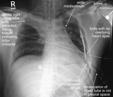
Figure 6-114 Knife wound to chest.
This 33-year-old male presented with a self-inflicted stab wound to the left chest. His chest x-ray shows a wide mediastinum. The left costophrenic angle is blunted, suggesting hemothorax, despite a left thoracostomy tube. This tube is badly positioned, as one of the fenestrations is not in the pleural space. A knife overlies the heart apex, though a single x-ray view cannot determine whether it lies within the patient. Given the wide mediastinum, a cardiac injury with blood in the mediastinum is possible. The right upper lobe is dense with cephalad retraction of the minor fissure, indicating right upper lobe collapse. CT was performed (Figures 6-115 and 6-116)
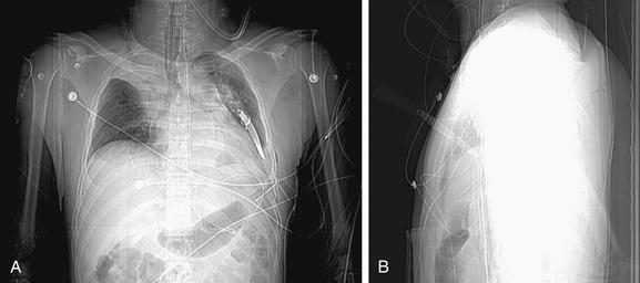
Figure 6-115 Knife wound to chest.
CT scout images from the patient in Figures 6-114 and 6-116. Given both the frontal (A) and the lateral (B) scout images, the knife is buried to the handle in the patient’s chest.
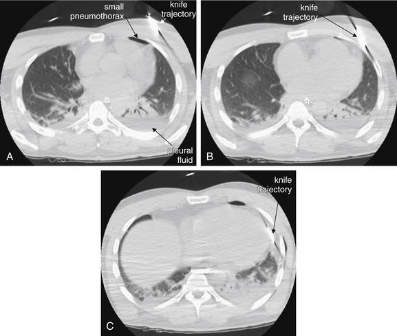
Figure 6-116 Knife wound to chest, CT without IV contrast.
Same patient as Figures 6-114 and 6-115. Lung windows. These CT images show the trajectory of the knife to skirt the pericardium. As a result of metal artifact, the precise location of the knife cannot be judged. No large pericardial effusion is seen. The CT was performed without intravenous contrast, so extravasation of contrast from the heart cannot be definitively ruled out. A small anterior pneumothorax is seen. Some dependent pleural fluid is visible. The patient underwent thorascopic surgery that showed no cardiac injury.
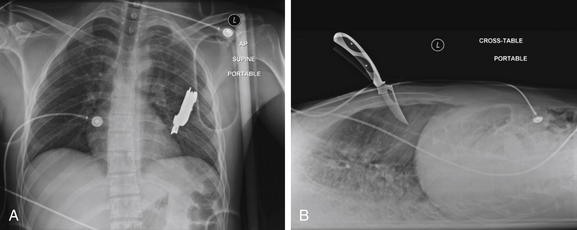
Figure 6-117 Knife wound to chest.
This 23-year-old male presented with a self-inflicted stab wound to the left chest. He was hemodynamically stable and alert, with the knife in place in the left chest wall, on emergency department arrival. Bedside echocardiography did not demonstrate a pericardial effusion. A portable chest x-ray was obtained. This x-ray demonstrates the importance of two orthogonal views when determining the location of a foreign body. A, The anterior–posterior (AP) view shows the knife to overlie the left chest, although in theory the knife could be outside of the patient, either behind or in front of his torso. B, In the lateral projection, the depth of penetration of the knife is revealed, although the position of the knife is not certain—in theory, it could lie outside of the patient to the left or right of the thorax. A, The anterior–posterior (AP) view shows the location to overlie the left chest, although in theory the knife could be outside of the patient, either behind or in front of his torso. Together, these views confirm a deep central stab wound to the chest. On the AP view, the knife appears to contact the left heart border, but penetration of the pericardium or heart is uncertain. A CT was obtained to delineate the knife’s position in greater detail (Figures 6-118 through 6-120). If the knife did not penetrate the pericardium, it could be removed at bedside, rather than requiring thoracotomy.
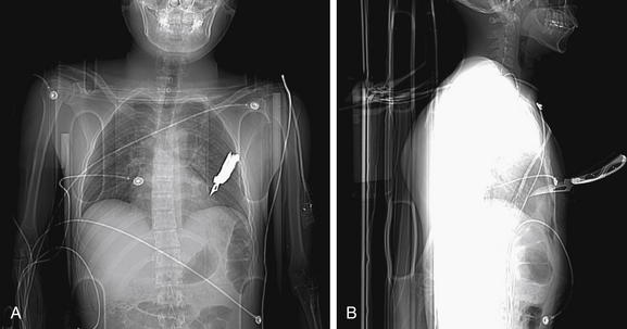
Figure 6-118 Knife wound to chest.
Figures 6-117 through 6-120 explore this case using x-ray and CT. Scout images from the CT reveal the same information depicted on chest x-ray (Figure 6-117). A, Frontal scout image. B, Lateral scout image.
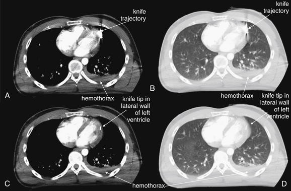
Figure 6-119 Knife wound to chest, CT with IV contrast.
Figures 6-117 through 6-120 include additional images from this case. A and C, Consecutive axial soft-tissue windows. B and D, Lung windows of the same axial slices shown in A and C, respectively. Soft-tissue windows show the knife tip to lie within the lateral wall of the left ventricle. There is no pericardial effusion. Remarkably, lung windows show no pneumothorax, although a small hemothorax is seen. In this case, CT provided important clinical information that determined patient management. X-ray (Figure 6-117) suggested an injury tangential to the heart, which could possibly have been managed nonoperatively by removal of the knife in the trauma bay. CT prompted thoracotomy. Intraoperatively, the patient had brisk myocardial bleeding that could have resulted in pericardial tamponade if a pericardial window had not been created.

Figure 6-120 Knife wound to chest.
Figures 6-117 through 6-119 include additional images from this case. The knife tip is seen in the lateral wall of the left ventricle on this close-up CT image. Contrast is not seen to escape the ventricle.
Bones
Chest x-ray can provide useful initial information about bony injuries, including fractures and dislocations. CT is more sensitive, but for many injury patterns, an injury does not require definitive visualization for adequate treatment, and CT may not alter management. For example, nondisplaced rib fractures may be invisible on x-ray but usually require only supportive care with analgesics. Dedicated rib x-rays can be obtained to improve sensitivity, but these are generally unnecessary, as standard chest x-ray provides the more clinically important information—namely, the presence of underlying injuries such as pneumothorax or pulmonary contusion. Bones visible on standard frontal (AP or PA) chest x-ray include ribs, sternum, scapula, proximal humerus, clavicles, thoracic spine, and portions of the cervical and lumbar spine. Joints visible on chest x-ray include the sternoclavicular, acromioclavicular (AC), and glenohumeral joints, as well as the articulations of ribs with spinal facets. These joints should be inspected for dislocation or subluxation. Dislocations of the sternoclavicular joints are discussed in this chapter, whereas acromioclavicular and glenohumeral joint dislocations are discussed in Chapter 14.
Fractures
Fractures can be subtle on chest x-ray. When specific bony fractures are suspected clinically or abnormalities are seen on chest x-ray, dedicated views of the affected region may be needed, depending on the specific injury. On x-ray, the contours of bones should be inspected for cortical step-offs. Comparison with structures on the contralateral side should be used to reveal subtle abnormalities.
Rib Fractures
Rib fractures are the most common thoracic injury and are a frequent finding on chest x-ray after trauma (Figures 6-121 through 6-124).26 Rib films are not typically indicated to assess for rib fracture, as it is the underlying parenchymal injury or the clinical status of the patient that most often drives management.26 The x-ray should be inspected for associated pneumothoraces, pleural effusions (hemothorax), and pulmonary contusions. CT is also not routinely indicated to pursue rib fractures, unless other important thoracic injuries are suspected.
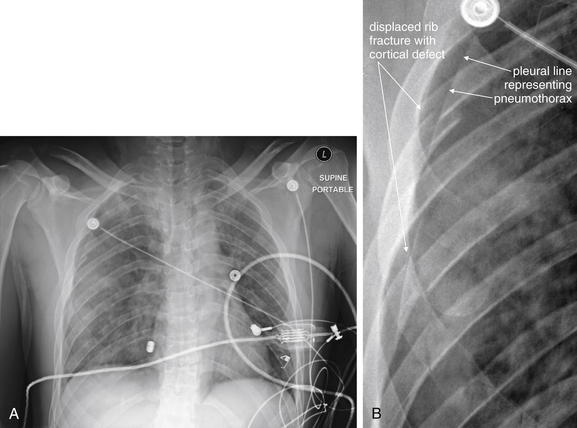
Figure 6-121 Rib fractures: Chest x-ray.
This 27-year-old male crashed his motorcycle at an estimated speed of 100 mph. On emergency department arrival, he complained of difficulty breathing. His chest x-ray shows multiple right-sided rib fractures (A), as demonstrated in the close-up (B), which shows the disrupted cortex of several ribs. Perhaps more importantly, the patient has a moderate-sized pneumothorax and opacities that may represent pulmonary contusion. These other abnormalities are reviewed in more detail in Figures 6-122 through 6-124.
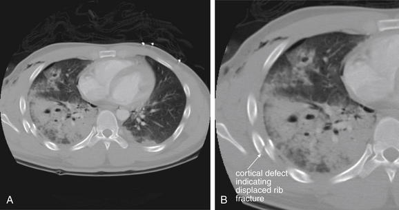
Figure 6-122 Rib fractures: CT with IV contrast.
Figures 6-121 through 6-124 include images from this case. A, Axial CT image viewed with bone windows. B, Close-up from A. On CT scan, this patient has several findings, which demonstrates the importance of inspecting the chest using appropriate window settings for the suspected injury. Bone windows demonstrate a displaced right rib fracture. Although fractures may be visible on other window settings when badly displaced, bone windows are optimized for evaluation of the cortex and allow detection of even minimally displaced fractures. Other abnormalities are seen on this view, including a significant pulmonary contusion, but these would be better viewed on lung windows. IV contrast was given for evaluation of other injuries, although it is not needed for assessment of bone.
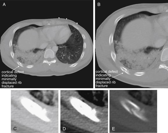
Figures 6-121 through 6-124 include other images from this case. A, Axial CT slice viewed with bone windows. B, Close-up from A. A more posterior rib fracture is less displaced and thus subtler. Note how this rib fracture is not easily seen on lung or soft-tissue window settings, because bone is excessively bright on these settings. Compare the window settings in C (lung), D (soft tissue), and E (bone).
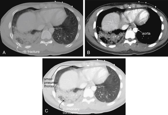
Figure 6-124 Rib fractures, CT.
Figures 6-121 through 6-124 include images from this case. This figure emphasizes the importance of inspecting the chest for trauma using window settings appropriate to the suspected injury. Bony injuries are best evaluated on bone windows (A). The aorta and other mediastinal structures should be inspected on soft-tissue settings (B). Lung parenchyma and pneumothoraces are best seen on lung windows (C). The various injuries present in this single slice are highlighted by the three window settings. The small right pneumothorax is essentially invisible on soft-tissue windows but is visible on lung and bone windows. Is a pneumothorax present on the patient’s left? Soft-tissue windows again offer no help, but the lung window image clearly rules this out. The rib fracture could easily be missed on soft-tissue or lung windows. The extent of the pulmonary contusion is best seen on lung windows—it appears smaller on soft-tissue windows, as only the densest central region is visible. The aorta is best inspected for defects on soft-tissue windows, which offer the best contrast with surrounding structures.
Ribs should be traced from their articulation with the facets of the thoracic spine, through their course, to the sternum. Displaced fractures are usually readily apparent and should not distract from a separate thorough search for associated pneumothorax, hemothorax, or pulmonary contusion as described earlier. Subtle cortical defects can be harder to recognize. The overlap of ribs can create confusing intersecting lines that may be mistaken for or may disguise fractures. Solitary rib fractures may occur, but as with other ring structures in the body, ribs often fracture in multiple locations or become displaced at articulations with other structures, so detection of a rib fracture should prompt a search for additional fractures or dislocations. If two or more adjacent ribs are fractured in two or more places, a “flail segment” is present, which may significantly interfere with respiratory mechanics. Patients with flail segments are at increased risk for respiratory failure requiring mechanical ventilation with either continuous positive airway pressure or endotracheal intubation.27 Fractures of the first and second ribs historically have been associated with high-energy mechanisms of trauma and with aortic trauma. However, several studies suggest no increased risk for aortic injury with upper rib, sternal, scapular, or thoracic spine fractures.17,18,26,28 Lee et al.17,18 found that the rate of thoracic aortic injury increased in a statistically significant but not a clinically meaningful degree in patients with rib fractures.17,18
Stawicki et al.29 noted an increase in mortality associated with rising numbers of rib fractures, particularly in the elderly. Overall, it is likely that rib fractures are a marker of high-energy trauma and morbidity from other injuries (including extrathoracic injuries), although in this study multiple rib fractures were independent predictors of mortality. Lee et al.18,30 suggested that three or more rib fractures were an indication for transfer to a trauma center, because of increased mortality, mean injury severity score, mean hospital stay, mean number of intensive care unit days, and rates of liver and spleen injuries. Other studies have shown that pain from rib fractures is a significant cause of disability, with pain persisting well beyond 30 days in some cases.31
Sternum Fractures
Sternal fractures are a marker of significant force to the thorax (see Figures 6-125 through 6-129). Associated injuries such as blunt cardiac injury, mediastinal injury, and pneumothorax should be considered. Sternal x-rays are not routinely performed, because they yield relatively little clinically important information. If associated injuries to the aorta are strongly considered, chest CT can evaluate these while allowing examination of the sternum using bone windows.
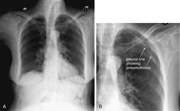
Figure 6-125 Sternal and manubrial fractures.
A, Frontal chest x-ray. B, Close-up from A. This 92-year-old female was a restrained driver in a collision with a truck and complained of chest pain. Her chest x-ray is notable for a left pneumothorax. Because of her sternal tenderness, a lateral sternal x-ray was obtained, suggesting a fracture. CT of the chest did confirm a nondisplaced sternal fracture, though no specific therapy was needed. The typical frontal x-ray obtained in trauma is not sensitive for sternal fracture, and none was noted on the chest x-ray in this figure. Compare with the lateral sternal x-ray and CT images in Figure 6-126.
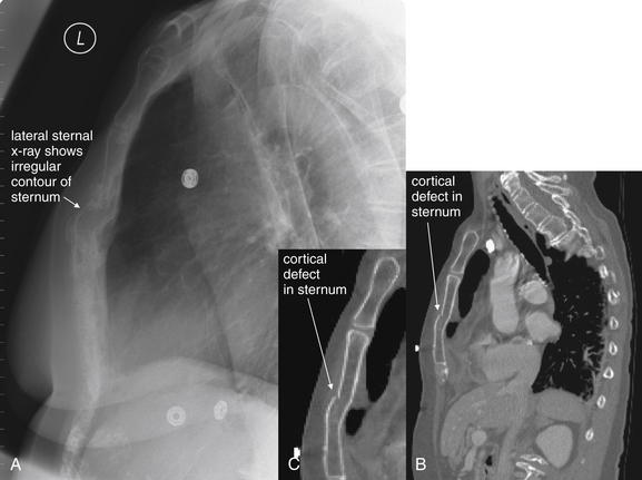
Figure 6-126 Sternal and manubrial fractures.
Same patient as in Figure 6-125. A, Lateral sternal x-ray. B, Sagittal CT image, viewed with bone windows. C, Close-up from B. Compare this with the sagittal reconstructions from her chest CT, which confirm a cortical defect of the sternum. No specific therapy was needed. Chest CT with IV contrast in this case was indicated for evaluation of the aorta, more so than for sternal evaluation.
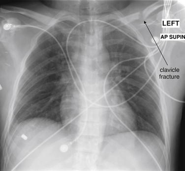
Figure 6-127 Sternal and manubrial fractures.
This 30-year-old male crashed his car at 70 mph. His airbag deployed, and he was wearing a seat belt with a shoulder strap at the time of the collision. His chest x-ray shows a left clavicle fracture—a CT was performed to evaluate the aorta and incidentally showed a sternal fracture (Figure 6-128). Like most sternal fractures, this one is not visible on anterior–posterior chest x-ray.
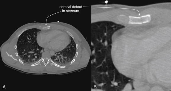
Figure 6-128 Sternal and manubrial fractures.
Same patient as Figure 6-127. A, Axial CT slice viewed with bone windows. B, Close-up from A. This 30-year-old male crashed his car at 70 mph. His airbag deployed and he was wearing a seat belt with a shoulder strap at the time of the collision. CT was performed to evaluate the aorta and incidentally showed a sternal fracture. On soft-tissue windows, this nondisplaced fracture would not be visible—not that any specific therapy would be required.
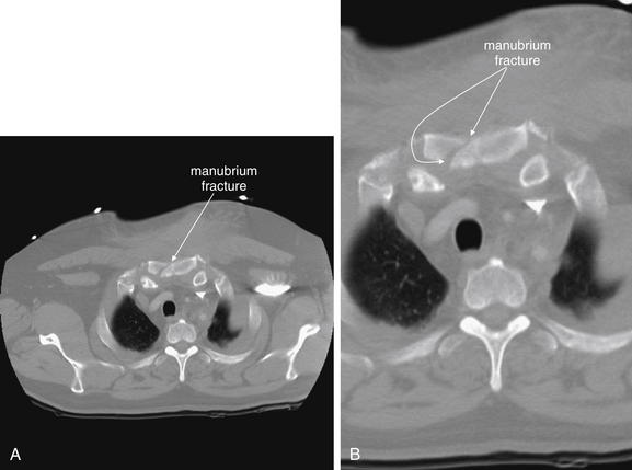
Figure 6-129 Sternal and manubrial fractures.
A, Axial CT slice, bone windows. B, Close-up from A. This 51-year-old male collided head on with another vehicle. His chest x-ray was nondiagnostic, but CT showed a manubrial fracture. Again, the purpose of chest CT in this circumstance is to evaluate for associated mediastinal injury, not to evaluate for manubrium fracture, which is treated nonsurgically in almost every case.
Sternal fractures are often not seen on the frontal chest x-ray. In some cases, they can be recognized by a subtle area of lucency or increased density, depending on the fracture pattern. A lateral chest x-ray or sternal view can depict the degree of AP displacement (see Figure 6-126). CT reveals more definition of the degree of fracture (see Figures 6-126, 6-128, and 6-129) but is generally more important for revealing associated injuries such as mediastinal trauma, as sternal fractures themselves require primarily supportive care with analgesics.32 A sternal fracture should prompt careful attention for possible sternoclavicular dislocation (Figures 6-130 through 6-135), as described later. A separate careful assessment of the mediastinum should be performed, as described earlier.
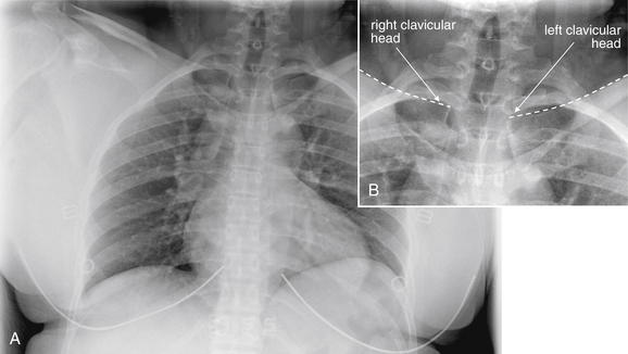
Figure 6-130 Sternoclavicular dislocation.
Dislocations of the medial head of the clavicle can be life threatening yet subtle on x-ray. This 43-year-old female was a seat-belted driver struck on the driver’s side by a second vehicle. Her chest x-ray was interpreted as normal by the radiologist, but she complained of severe pain near her sternal notch. Compare with the CT images in Figures 6-131 through 6-133. In retrospect, her left clavicular head appears slightly inferiorly displaced, although this could be a positional artifact. Resulting from the chest x-ray exposure, this is difficult to see, but if we carefully follow the superior border of each clavicle toward the midline, the asymmetry becomes apparent. A, Frontal chest x-ray. B, Close-up from A.
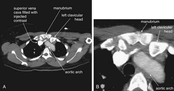
Figure 6-131 Sternoclavicular dislocation, CT with IV contrast.
Same patient as in Figure 6-130. A, Axial CT image. B, Close-up from A. This computed tomography slice is a conventional image of the type most emergency physicians would have immediately available for viewing. The slice is viewed on soft-tissue windows to highlight the relationship of the left clavicle to the aortic arch. The left clavicular head is displaced posteriorly relative to the sternum, and it is close to the aortic arch. Compare with the reformatted images in Figures 6-132 and 6-133, which illustrate the dislocation even more clearly. This patient was taken to the operating room by the orthopedic service, and the chest was prepped for possible thoracotomy, with thoracic surgeons standing by. A closed reduction was performed without incident.
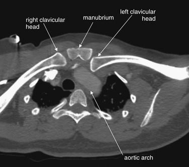
Figure 6-132 Sternoclavicular dislocation, CT with IV contrast.
Figures 6-130 through 6-133 include images from this case. This Maximum Intensity Projection (MIP) reconstruction uses a thickened image slab to allow both clavicles and the sternum to be seen in the same plane. The left clavicle is clearly seen to be displaced posteriorly, touching the aortic arch. The patient underwent closed reduction in the operating room, with thoracic surgeons standing by.
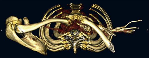
Figure 6-133 Sternoclavicular dislocation.
Figures 6-130 through 6-132 include images from this case. This three-dimensional reconstruction is viewed looking down upon the thoracic inlet. This is the opposite of the conventional orientation for axial computed tomography, where the point of view is that of an observer looking up from the patient’s feet. The left clavicle is seen posteriorly displaced.
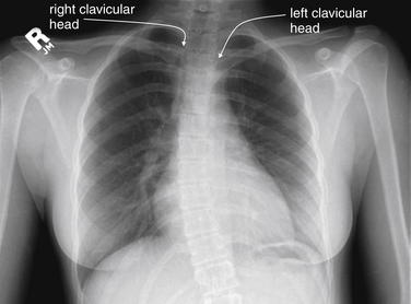
Figure 6-134 Sternoclavicular dislocation.
This young woman has the same injury as the prior patient—a left sternoclavicular dislocation. Her chest x-ray more readily demonstrates the asymmetry of the clavicular heads at the sternoclavicular joints. Compare with the CT images in Figure 6-135.
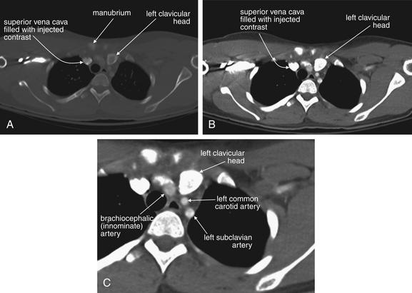
Figure 6-135 Sternoclavicular dislocation.
CT images from the same patient as in Figure 6-134. A, Axial CT image, bone window. B, Same CT slice viewed with soft-tissue window. C, Close-up from B. The left clavicular head is posteriorly displaced and impinges upon the great vessels emerging from the aortic arch (brachiocephalic, left common carotid, and left subclavian). Like the patient in Figures 6-130 through 6-133, this patient underwent closed reduction in the operating room, with thoracic surgeons prepped for possible thoracotomy.
Scapular Fractures
Scapular fractures are also discussed in Chapter 14. Here, we briefly describe these injuries, because they may be noted on x-ray obtained for chest trauma. Scapular fracture can be subtle on frontal chest x-ray. The entire perimeter of the scapula should be traced to assess for cortical step-offs. The medial border of the scapula can be mistaken for the pleural line of a pneumothorax, and vice versa, so a separate careful search for pneumothorax should be performed as described earlier. The scapular spine and the cup of the glenoid fossa should be inspected for discontinuities. If scapular fracture is suspected, CT provides detailed three-dimensional information. Scapula fractures have been associated with high-energy trauma and to a lesser degree with aortic injury, so careful evaluation of the mediastinum should also be performed when scapular fracture is detected. Scapular injuries can occur in patients without other chest trauma, so aortic imaging is not mandatory in a stable, alert patient with no signs or symptoms of aortic injury on examination or chest x-ray.
Humerus Fractures
The proximal humerus is visible on frontal chest x-ray and should be inspected for fractures, which are discussed in detail in Chapter 14.
Clavicular Fractures
Clavicular fractures are common following falls, bicycle accidents, and motor vehicle collisions. These fractures are discussed in more detail in Chapter 14. The clavicle should be inspected for cortical defects from its articulation with the sternum (discussed later in this chapter) to the AC joints (see Chapter 14). A clavicle fracture should prompt careful reexamination of the AC and the sternoclavicular joints, which may be dislocated or separated by a fracture. The degree of displacement and impaction or overriding should be noted. Most clavicular fractures are treated nonoperatively, but severely displaced fractures may be fixed surgically. Careful examination of the underlying lung for pneumothorax should be performed as described earlier.
Spine
The thoracic spine and portions of the cervical and lumbar spine are visible on frontal and lateral chest x-ray. When spine injury is suspected clinically, dedicated imaging of these regions is mandatory and is described in detail in Chapter 3. Gross deformity of the spine should be assessed for on chest x-ray.
Dislocations
Sternoclavicular Joints
Sternoclavicular dislocation can be a radiographically subtle but life-threatening injury. Posterior dislocation of these joints can result from deceleration mechanisms such as motor vehicle collisions and falls. This can lead to impingement of the clavicular head upon the aortic arch and its major branches, the brachiocephalic, innominate, and subclavian arteries (see Figures 6-130 through 6-135), sometimes requiring operative reduction or closed reduction in the operating room.33 The normal appearance of the sternoclavicular joints is the bilaterally symmetrical location of the clavicular heads on each side of the upper sternum. Rotation of the patient can cause apparent asymmetry, simulating sternoclavicular dislocation. In true dislocation, one clavicular head usually appears superior or inferior to the other and may appear medially or laterally displaced. A lateral chest x-ray or sternal view can confirm sternoclavicular dislocation but does not depict associated vascular injury. CT is useful to further characterize the degree of dislocation and the location of the clavicle relative to the great vessels. CT also depicts mediastinal hematoma or overt vascular injury resulting from sternoclavicular dislocation.32
Acromioclavicular Joints
AC joint injuries are discussed in more detail in Chapter 14. The AC joints are visible on frontal chest x-ray. The normal AC joints are bilaterally symmetrical, so comparison of the left and the right AC joints should be a routine part of your evaluation. A normal AC joint is generally no more than 4 mm in width, though variation occurs and comparison with the opposite side may be more useful than a fixed measurement.34
Glenohumeral Joints
Glenohumeral joint injuries are discussed in more detail in Chapter 14. The humeral head is visible on frontal chest x-ray and should be located within the cup of the glenoid fossa. The glenohumeral joints should be bilaterally symmetrical, so always compare the left and the right. Theoretically, posterior or anterior dislocation of the humeral head could be missed on a single frontal projection, because this view does not indicate the AP position of the humerus relative to the glenoid fossa. If glenohumeral dislocation is suspected clinically or if an abnormality is seen on chest x-ray, a dedicated shoulder series should be obtained.