The Second Stage of Comprehensive Treatment
Correction of Molar Relationship and Space Closure
At the beginning of the second stage of treatment, the teeth should be well aligned, and any excessive or reverse curve of Spee should have been eliminated. The objectives of this stage of treatment are to correct molar and buccal segment relationships to provide normal occlusion in the anteroposterior plane of space, close extraction spaces or residual spaces in the arches, and correct excessive or negative overjet. This is possible only if the jaw relationships are reasonably correct, which means that orthognathic surgery must be considered for the most severe problems. Indications for surgical treatment and the orthodontist–surgeon interaction are discussed in Chapter 19.
Correction of Molar Relationship
Orthodontic correction of the molar relationship nearly always involves moving from a Class II or partially Class II relationship to Class I, although occasionally the treatment will be aimed at a Class III problem. Excluding surgery to reposition the jaws, there are two possibilities: (1) differential growth of the jaws, guided by extraoral force or a functional appliance or (2) differential anteroposterior movement of the upper and lower teeth, with or without differential closure of extraction spaces. These approaches are not mutually exclusive, but even when growth modification is successful, it typically provides only a partial correction of a full-cusp Class II or Class III malocclusion. Some tooth movement almost always is needed to complete the correction of the molar relationship.
Differential Growth in Adolescent Class II Treatment
The use of extraoral force or functional appliances to influence jaw growth is discussed in some detail in Chapter 13. The different timing of skeletal growth in males and females must be kept in mind when this approach is used. During adolescence, the mandible tends to grow forward more than the maxilla, providing an opportunity to improve a skeletal Class II jaw relationship. Girls mature considerably earlier than boys and are often beyond the peak of the adolescent growth spurt before the full permanent dentition is available and comprehensive orthodontic treatment can begin. Boys, who mature more slowly and have a more prolonged period of adolescent growth, are much more likely to have a clinically useful amount of anteroposterior growth during comprehensive treatment in the early permanent dentition.
When either extraoral force (headgear) or a functional appliance is used to modify growth in Class II patients, a favorable response includes both restraint of maxillary growth and differential forward mandibular growth. In skeletally immature patients with a permanent dentition, there is nothing wrong with a first phase of functional appliance treatment, even though the permanent teeth have erupted, and then a fixed appliance to obtain detailed occlusal results, but headgear is more compatible with the fixed appliances needed for comprehensive treatment. A removable functional appliance alone is unlikely to provide a satisfactory result in the early permanent dentition, and it will have to be modified or discontinued when the fixed appliance treatment begins. Many clinicians would like to believe that Class II elastics (or fixed springs that have the same effect) can influence growth, as well as move teeth. Unfortunately, the evidence indicates that growth modification in adolescent patients is unlikely with elastics or flexible spring devices.1,2 In an adolescent in the early permanent dentition, a rigidly coupled fixed functional appliance like the Herbst appliance effectively corrects Class II molar relationships (with varying combinations of differential growth and forward displacement of mandibular teeth), but headgear can be quite effective in a cooperative patient and does not introduce a Class II elastics effect.
An ideal patient for headgear in the early permanent dentition is a 12- to 14-year-old boy with a Class II problem, whose skeletal maturity is somewhat behind his stage of dental development, and who has good growth potential (Figure 15-1). Boys at age 13, it must be remembered, are on the average at the same stage of maturation as girls at 11, and significant skeletal growth is almost always continuing. On the other hand, girls at age 13 are, on the average, at the same developmental stage as boys at 15, and by this time, clinically useful changes in jaw relationship from growth guidance are unlikely.
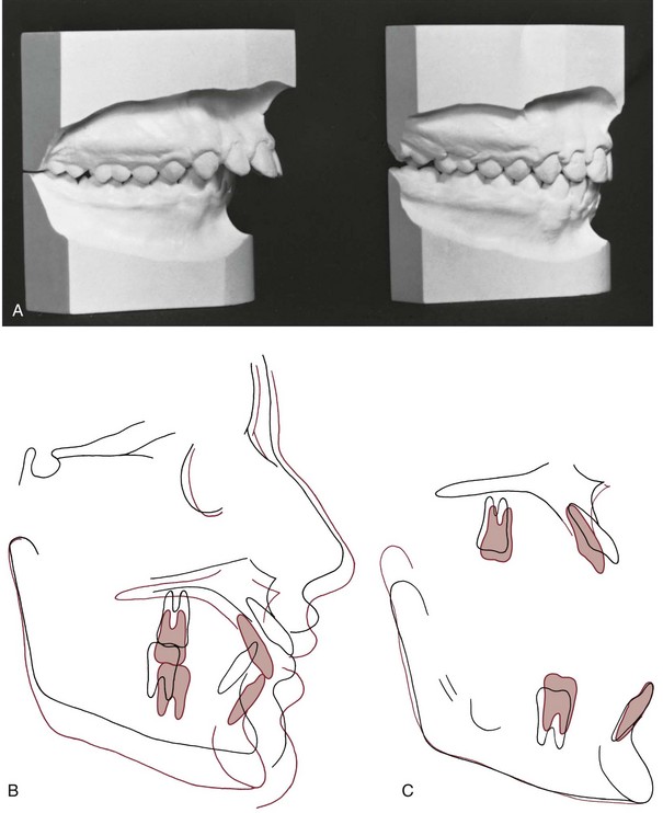
FIGURE 15-1 Class II correction in a 13-year-old boy, using extraoral force to the maxilla. A, Dental casts before and after treatment. B and C, Cephalometric superimposition showing treatment changes. Note the large amount of vertical growth, which allowed the maxilla and maxillary dentition to be displaced distally as they moved vertically, while the mandible grew downward and forward. As the maxillary and mandibular superimpositions show, overbite was corrected by relative intrusion (i.e., the lower incisors were held at the same vertical level while the molars erupted). There was relatively more eruption of the mandibular than the maxillary molar, reflecting the upward-backward direction of headgear force, and only a small amount of distal movement of the upper molars.
Although correction of molar relationship is a major goal of the second rather than the first stage of treatment, there is no reason to wait for alignment and leveling to be completed before beginning headgear or a fixed functional appliance, especially since every passing day decreases the probability of a favorable growth response.
Although the main purpose of headgear is growth modification, some tooth movement in all three planes of space inevitably accompanies it when the extraoral force is delivered to the teeth. With headgear for Class II correction, when there is good vertical growth and the maxillary molars are allowed to elongate, the maxillary teeth erupt downward and backward, and spaces may open up in the maxillary arch. Even though the extraoral force is applied against the first molar, it is unusual for space to develop between the first molar and second premolar. Instead, the second and, to a lesser degree, the first premolars follow the molars. The result is often a space distal to the canines, along with a partial reduction of overjet as the jaw relationship improves (Figure 15-2).
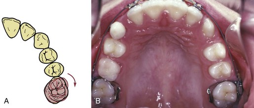
FIGURE 15-2 A, In patients with Class II malocclusion, the upper molars usually are rotated mesially, and part of the apparent backward movement of the first molar is a distal rotation of the buccal cusps as the tooth rotates around its lingual root. The inner bow of a headgear facebow should be adjusted to produce this type of rotation. B, Space tends to open within the maxillary arch when extraoral force to the upper first molars is used and the patient grows well, as in this patient after 12 months of headgear treatment during the adolescent growth spurt. Note that as the molars moved distally, the gingival fiber attachments produced distal movement of the premolars, opening space between these teeth and the canines. When a complete fixed appliance is placed at this stage, one of the first steps is consolidation of the space distal to the canines.
When this result occurs, the preferred approach is to consolidate space within the maxillary arch at a single location, using elastomeric chains to bring the canines and incisors into an anterior segment and the molar and premolars into a posterior segment. When the molar relationship has been corrected, the residual overjet is then reduced by retracting the incisors in this nonextraction patient in exactly the same way as in a patient who had a first premolar extraction space (see the following discussion). Extraoral force should be continued until an intact maxillary arch has been achieved. Discontinuing it when only the molar relationship has been corrected is unwise, both because the maximum skeletal effect probably has not been obtained at that point and because the retraction of the incisor teeth requires posterior anchorage, which can be reinforced by the headgear.
In the early permanent dentition, space opening within the maxillary arch rarely occurs when a Herbst appliance or some of its modern variants (see Figure 10-7) are used. Bonding the teeth that are available (canines and incisors in both arches, maxillary premolars) allows alignment and stabilization of the lower incisors while molar correction is occurring and facilitates the transition to a regular fixed appliance, which usually occurs after about 12 months of Herbst treatment. With a lingual appliance (now increasingly used in adolescents as well as adults), a Herbst appliance also can be an effective way to correct a Class II molar relationship. The precisely fitting lingual archwire controls the inclination of the lower incisors quite well.3
Class II Correction by Distal Movement of Upper Molars
The concept of “distal driving” the maxillary posterior teeth has a long orthodontic history.4 After early cephalometric studies in the 1940s showed that little or no distal movement of upper molars was produced by the Class II elastic treatment of that era, headgear was reintroduced as a means of moving the upper molars back. Palatal anchorage also has been used to create distal movement of upper molars and to create a space into which the anterior teeth can be retracted, and skeletal anchorage (bone screws or bone anchors) now offers a more effective way to accomplish distal movement.
Although the modern methods discussed below have improved the situation, Class II correction by distal movement of upper molars has definite limits that are important to understand and respect. With headgear, it is now clear that significant distal positioning of the upper posterior teeth relative to the maxilla occurs primarily in patients who have vertical growth and elongation of the maxillary teeth (see Figure 15-1). Without this, it is difficult to produce more than 2 to 3 mm of distal movement of the upper molars, unless the upper second molars are extracted (see later). Appliances based on palatal anchorage are somewhat more successful in moving upper molars back, but complete Class II correction by this mechanism is unlikely. With skeletal anchorage above the roots of the teeth, 4 to 6 mm of distal movement is quite possible, but moving molars back requires space behind them, and second molar extraction may be required for major distalization. If second molars are to be distalized, early removal of third molars is advised—otherwise they may become significantly impacted and difficult to extract.
Molar Rotation as a Factor in Distalization
In patients with mild-to-moderate skeletal Class II malocclusion, the upper molars are likely to have rotated mesially around the lingual root, and merely correcting the rotation changes the occlusal relationship in a Class I direction (see Figure 15-2). This can be done with a transpalatal lingual arch, an auxiliary labial arch, or the inner bow of a facebow. Sometimes upper molars are so mesially rotated that it is difficult or impossible to insert a facebow until the rotation has been partially corrected with a more flexible appliance (such as a heavy labial arch, typically 36 mil steel, inserted into the headgear tubes and tied over an initial alignment archwire). Correction of rotated maxillary first molars is the first step in Class II treatment of almost every type.
Anchorage Systems for Distal Movement of Molars
Mesial movement of teeth is easier than distal movement, simply because there is much more resistance to distal movement. Successful distal movement of molars therefore requires more anchorage than can be supplied by just the other teeth.
Palatal Anchorage: The relative stability of the anterior palate, both the soft tissue rugae and the cortical bone beneath them, is one possibility for obtaining this additional anchorage. Although removable appliances contact the palate, they are not effective in moving molars back, probably because they do not fit well enough. A fixed appliance that stabilizes the premolars and includes a plastic pad contacting the rugae is needed. Fortunately, most patients tolerate this with minimal problems, but contacting the palatal tissue has the potential to cause significant tissue irritation, to the point that the appliance has to be removed.
Once palatal anchorage has been established, there are several possibilities for generating the molar distalizing force. Austenite nickel–titanium (A-NiTi) coil springs compressed against the molars (from an anterior anchorage unit) produce an effective and nearly constant force system for the distal movement. Magnets in repulsion also can be used (Figure 15-3), but the amount of force changes markedly as tooth movement occurs. A-NiTi springs have the additional advantage of being less bulky and usually are a better choice. The pendulum appliance (Figure 15-4) uses beta-titanium (beta-Ti) springs that extend from the palatal acrylic and fit into lingual sheaths on the molar tube, which gives greater control of these teeth
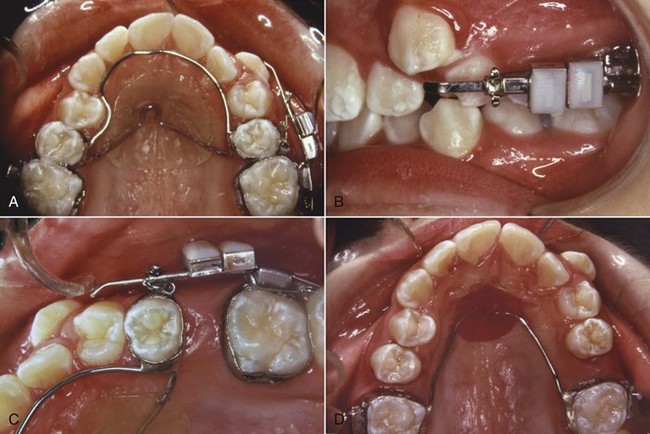
FIGURE 15-3 The use of magnets in repulsion to distalize maxillary first molars, initially only on the right side. A, Stabilizing lingual arch from second premolars, with one magnet attached to the premolar and the other to the first molar on the right side. B, Facial view of the magnet assembly. Note the arrangement for repositioning the premolar magnet as the molar moves back, to maintain the force. C, Progress: space opened at the rate of about 1 mm/month. D, Nance arch in place to maintain the molars (the left molar was distalized for 3 months, the right molar for 6 months) while distal drift of premolars occurs. A complete fixed appliance was placed a few months later to complete the treatment. (Courtesy Dr. Wick Alexander.)
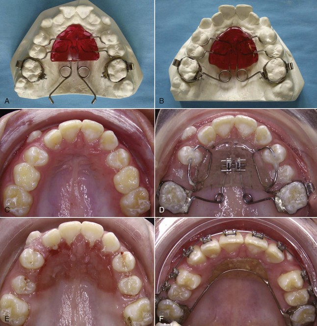
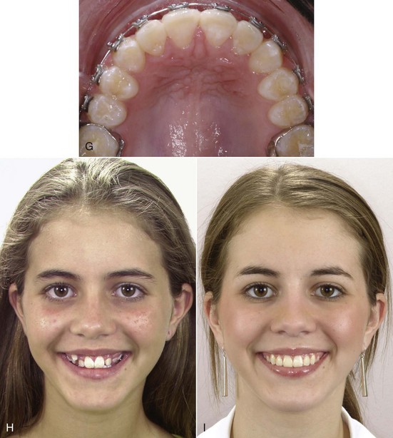
FIGURE 15-4 Pendulum appliance for molar distalization. A and B, Appliance on cast before and after activation of the springs. These are formed from beta-Ti wire and should deliver 200 to 250 gm force (steel wire is too stiff, produces too much force). C, Occlusal view of a patient with the maxillary canines nearly blocked out of the arch (in an individual who can afford some increase in maxillary incisor prominence). D, Pendulum appliance with both a jackscrew for transverse expansion and molar distalizing springs (this modification is called the T-Rex appliance). E, Removal of the appliance. Note the increase in space in the arch and the irritation of the palatal tissue beneath the appliance. Both are typical responses. F, A Nance lingual holding arch in place as fixed appliance treatment begins. It is easier to move maxillary molars distally than to keep them there as further treatment proceeds, and a lingual arch is necessary for stabilization before and during further treatment. G, Alignment of the upper arch completed. H, Initial smile. I, Smile after treatment. (A and B courtesy Professor A. Darendeliler.)
In a small but well-characterized sample of patients who were treated to a super-Class I molar relationship with the pendulum appliance activated to produce 200 to 250 gm, Byloff et al found that molar movement averaged just over 1 mm/month (1.02 ± 0.68), with a considerable degree of distal tipping of the crown and an elevation of the molar (Figure 15-5, A).5 As one would expect, despite the contact of the appliance with the palate, the premolars and incisors were tipped anteriorly, but the molar moved distally 2 to 3 times as far as the anchor teeth. When the appliance was modified to minimize distal tipping of the molar, the distal movement of the molar crown was similar, but greater distal movement of the roots was obtained at the cost of increased treatment time and some additional forward movement of the incisors (Figure 15-5, B).6
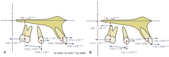
FIGURE 15-5 A, Mean changes in tooth position relative to the maxilla in a sample of 13 patients with activation of a pendulum appliance with 250 gm force and no tipback bends. B, Mean changes in 20 patients with a similar pendulum appliance incorporating tipback bends. The tipback bends reduced tipping of the molar as it moved distal and led to greater distal movement of the roots, at the cost of increased displacement of the incisors and increased treatment time. (Redrawn from Byloff FK, Darendeliler MA, Clar E, et al. Angle Orthod 64:261-270, 1997.)
However the molars were moved distally, they must be held there while the other teeth are then retracted to correct the overjet (see Figure 15-3). It is one thing to move molars back, and something else to maintain them in that position. Simply leaving the distalization appliance in place for 2 to 3 months leads to distal movement of the premolars by stretched gingival fibers, but as soon as the original premolar-based lingual arch and palatal pad are removed, a new lingual arch and pad from the distalized molars must be placed. Even so, especially if the molar tipped distally, it will tip mesially again as the space closes. Placing a tipback in the distalizing springs will keep the molar more upright and minimize relapse, but this increases the extrusive tendency, so as with headgear, the most successful molar distalization with the pendulum appliance occurs in patients who have vertical growth during their treatment. Even so, data show that on the average, much of the original distalization is lost during the second phase of treatment with a complete fixed appliance (Figure 15-6).
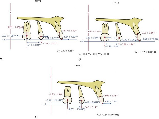
FIGURE 15-6 Mean changes in tooth position relative to the maxilla in a sample of 35 Class II patients treated with a first phase of molar distalization followed by comprehensive fixed appliance treatment. A, Changes during phase 1. The average age at the start of treatment was 12.3 years (S.D ± 1.5 years), and the treatment duration was 0.7 ± 0.2 years. Note that in phase 1, on the average, the molar moved back about twice as far as the incisor moved forward, but the increase in space between the molar and premolar was due to nearly as much forward movement of the premolar as distal movement of the molar. The molar tended to intrude, while the premolar was extruded. The large standard deviations emphasize that, as usually is the case, changes in individual patients varied considerably. B, Changes during phase 2, duration 2.4 ± 0.6 years. During this time, the changes in tooth positions relative to the maxilla that were created during pendulum treatment were recovered to a considerable extent. Note the vertical changes, consistent with vertical growth during adolescence. C, Changes from the beginning to completion of treatment, duration 3.1 ± 0.6 years, showing the small average net distalization of the molars relative to the maxilla. In the final analysis, successful correction of the Class II malocclusion in many of these patients was due more to jaw growth, transverse expansion of the dental arches, and forward movement of the incisors than to distalization of upper molars. (Courtesy Professor A. Darendeliler.)
Headgear or Class II Elastics: The problem with headgear for this type of tooth movement always has been that force of moderate intensity with long duration is needed, while headgear tends to supply relatively high force with only medium duration even in cooperative patients. Unless second molars are extracted (see below), significant distal movement of first molars (>2 mm) with headgear occurs only when the molar is extruded simultaneously, which is acceptable in a patient with substantial growth in height of the ramus, but otherwise leads to unfavorable downward-backward rotation of the mandible. High-pull headgear is not very effective in distalizing molars.
In theory, force from Class II elastics also can be used to push the upper molars distally, by using a sliding jig to concentrate the force on the molars. This was a mainstay of the original Tweed technique. There is the risk of considerably more mesial movement of the lower teeth than distal movement of the upper teeth, however. In modern orthodontics, the major use of Class II elastics to a sliding jig would be to accentuate rotation of the upper molar as a component of correcting the molar relationship.
Skeletal Anchorage: At this point, the advantage of skeletal anchorage for distalization of molars is so great that it is rapidly replacing the previous methods. With miniplates or a long bone screw at the base of the zygomatic arch (Figure 15-7)7 or bone screws in the palate to stabilize a lingual arch with springs for distalization,8 all the maxillary teeth can be moved back simultaneously (see Figure 18-47). Alveolar bone screws also are a possibility, but if they are between tooth roots, they block mesiodistal changes in tooth position, so using them for distalization requires changing screw position during treatment. With skeletal anchorage of any type, a fixed appliance with NiTi coil springs provides the best force system for distal movement.
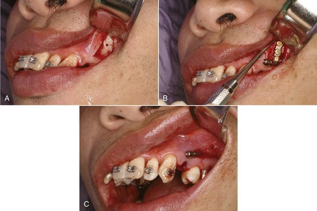
FIGURE 15-7 Placement of a bone anchor for maximum retraction of protruding maxillary incisors. A, Exposure of the zygomatic buttress area, initial hole for screw drilled. B, Anchor in place, secured by three bone screws. C, Soft tissue covering the anchor, with only the tube for attachment of a retraction spring exposed in the mouth.
Skeletal anchorage or not, two objects cannot occupy the same space at the same time, and there is only so much room at the rear of the maxillary arch. This means that in adolescents, extraction of the second molar (see below) may be necessary, and if second molars are distalized, early extraction of the third molar is indicated so that they do not end up impacted.
Distalization of First Molars After Second Molar Extraction
Moving upper first molars distally with any method is much easier if space is created by extracting the upper second molars. Although headgear has been shown to be effective in moving first molars into a second molar extraction site, it is now largely of historical interest because of the unfavorable force system and need for excellent patient cooperation. Palatal anchorage, as one would expect, also is more successful in moving the first molar distally when the resistance of the second molar has been removed. With both treatment methods, 4 to 5 mm short-term distal movement of the first molar is as much as can be expected even with second molar extraction, and, as we have noted above, much of this is likely to be lost long-term.
With skeletal anchorage, greater distalization of first and second molars is possible, but extraction of the upper second molars should be considered if the third molars are reasonably well formed. The same 75% to 80% chance that third molars would be satisfactory replacements for the second molars presumably would apply with use of skeletal anchorage, as it did with headgear for distalization.9
Occasionally, unilateral molar distalization is indicated, typically when a unilateral Class II malocclusion is present and there is a dental midline discrepancy. Extraction of one second molar facilitates this treatment, and the third molar usually replaces the missing second molar quite satisfactorily (Figure 15-8). Unilateral cervical headgear can be used for this treatment plan, but skeletal anchorage is definitely preferred now.
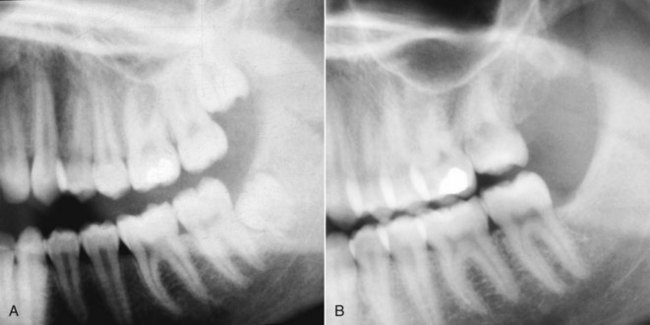
FIGURE 15-8 A, In this patient the treatment plan was extraction of the maxillary left second molar, so that the first molar and premolars on that side could be moved distally to correct a yaw of the maxillary arch. B, Posttreatment, with the third molar already erupting into the second molar extraction site. Eventually the remaining three third molars would be scheduled for extraction. A well-formed maxillary third molar can be a satisfactory replacement for an extracted second molar, and usually erupts in a way that facilitates the replacement.
It is difficult to distalize the upper teeth too much with headgear or palatal anchorage. Skeletal anchorage is so effective that overretraction of the upper incisors is possible, which of course becomes unsuccessful camouflage. This makes it all the more important to establish the desired final position of the incisors in planning treatment and then control tooth movement to reach this goal. In one sense, temporary anchorage devices (TADs) make it possible to do what only surgery could do previously: move the maxillary dentition back too much.
Differential Anteroposterior Tooth Movement Using Extraction Spaces
There are two reasons for extracting teeth in orthodontics, as discussed in detail in Chapter 7: (1) to provide space to align crowded incisors without creating excessive protrusion and (2) to allow camouflage of moderate Class II or Class III jaw relationships when correction by growth modification is not possible. A patient who is both Class II (or III) and crowded is a particular problem because the same space cannot be used for both purposes. The more extraction space is required for alignment, the less is available for differential movement in camouflage, and vice versa.
An important part of treatment planning is deciding which teeth to extract and how the extraction spaces are to be closed (i.e., by retraction of incisor teeth, mesial movement of posterior teeth, or some combination). These decisions determine the orthodontic mechanics.
Class II Camouflage by Extraction of Upper First Premolars
In the late 1980s, it was claimed by some dentists that extraction of upper first premolars would lead to later temporomandibular dysfunction (TMD) problems. The theory, to the extent that the proponents of this claim had one, was that retracting the upper incisors would inevitably lead to incisor interferences, and this would cause TMD. The claim was never supported by any evidence, and research data have refuted it.10,11 It is important to limit first premolar extraction for camouflage of Class II malocclusion to the appropriate patients and not to retract the incisors too much, but if this is done, it can be an excellent treatment method.
With this approach, the objective is to maintain the existing Class II molar relationship, closing the first premolar extraction space largely by retracting the protruding incisor teeth (Figure 15-9). Anchorage must be reinforced, but one method, Class II elastics from the lower arch, is specifically contraindicated unless the lower incisors need to be moved forward (which rarely is the case). The remaining possibilities are extraoral force to the first molars, a stabilizing lingual arch, retraction of the maxillary anterior segment with extraoral force directly against these teeth, or skeletal anchorage.
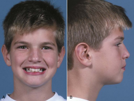
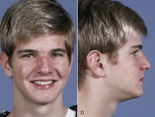
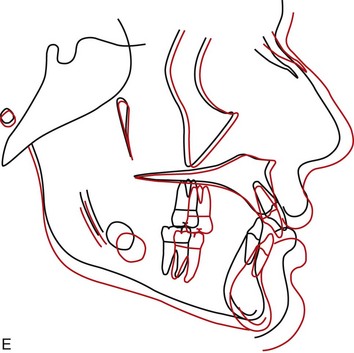
FIGURE 15-9 Effect of maxillary premolar extraction in a patient with a poor response to attempted nonextraction treatment. A and B, Facial appearance at the point that excessive maxillary incisor protrusion and persistent Class II molar relationship led to the decision for extraction of maxillary first premolars. C and D, One year later, at the completion of treatment. E, Cephalometric superimposition over the period of extraction treatment. (From Proffit WR, White RP, Sarver DM. Contemporary Treatment of Dentofacial Deformity. St. Louis: Mosby; 2003.)
Excellent reinforcement of posterior anchorage can be obtained with extraoral force only if it is applied consistently and for long durations. The more constant the headgear wear, the less a stabilizing lingual arch will be needed. Conversely, a stabilizing lingual arch augments the posterior anchorage full time, while headgear is likely to be worn a good bit less.
It seems intuitively obvious that a lingual arch with a button against the palatal tissue should be more effective than a straight transpalatal lingual arch, but when first molars are being stabilized in a premolar extraction case, this is not necessarily true. The effect of the lingual arch is primarily to prevent the molars from rotating mesiolingually around their palatal root and secondarily to prevent them from tipping mesially. A straight transpalatal lingual arch (see Figure 14-14) is as effective as one with a palatal button in preventing rotation, and for most patients, the marginally better stabilization with a palatal button is not worth the cost in tissue irritation. Note that this is true when a lingual arch is used to stabilize molars, but not true when the lingual arch is to stabilize premolars, as in the molar distalization technique discussed above. When pushed mesially, premolars tip more than they rotate, and a palatal button is needed on a lingual arch to stabilize them.
In addition to headgear and/or lingual arch stabilization, all the strategies described in Chapter 10 for reducing strain on anchorage (i.e., minimizing binding and friction, retracting canines individually, skeletal anchorage) are appropriate with upper first premolar extraction and can be brought into use.
Retracting protruding maxillary anterior teeth with headgear attached to the archwire (often called J-hook headgear) totally avoids strain on the posterior teeth and once was attractive from that point of view. This technique has two major disadvantages: (1) as with any headgear that provides too few hours and too much force, the force system is unfavorable for tooth movement and (2) there is significant binding and friction, not only where teeth slide along the archwire but also within the headgear mechanism itself because the headgear wires that attach to the teeth tend to bind against their protective sleeves. This makes it difficult to control the amount of force, and more net force on one side than the other may lead to an asymmetric response. In fact, it is unusual if space does not close faster on one side than the other. Only if the headgear is worn nearly full time (including school hours) will efficient tooth movement be obtained. For both reasons, headgear for direct retraction of the incisor segment rarely is used now.
Skeletal anchorage in these premolar extraction cases is a straightforward method of reinforcing anchorage, and retraction of the six anterior teeth usually can be managed satisfactorily with a single bone screw between the second premolar and first molar (see Figure 10-48). In adolescents, use of TADs is necessary only if maximum retraction of the anterior segment without any elongation of the incisors is desired, a situation more likely to be encountered in adults.
Extraction of Maxillary and Mandibular Premolars
Correction of Class II buccal segment relationships with extraction of all four first premolars implies that the mandibular posterior segments will be moved anteriorly nearly the width of the extraction space. At the same time, the protruding maxillary anterior teeth will be retracted without forward movement of the maxillary buccal segments. This, in turn, implies (though it does not absolutely require) that Class II elastics will be used to assist in closing the extraction sites.
The Begg technique is a classic illustration of using Class II elastics to produce differential movement of the arch segments while correcting the molar relationship. In the Begg approach (with the modernized appliance as well as the original one), at the beginning of the second stage of treatment light interarch elastics are added to help close space, while Class II elastics are continued (Figure 15-10). An anchor bend is placed in the upper archwire so that the maxillary anterior teeth are tipped back in part by the force system associated with the archwire itself. In the lower arch, the anchor bend is used to control the amount of mesial tipping of the molars. The Class II elastics reinforce and accentuate the differential tooth movements along the archwires. It is extremely important to use only light forces, so that optimum force levels are reached where tipping is desired, while forces for bodily movement remain suboptimum. The same approach is used with the Tip-Edge appliance, which allows the use of Begg-style mechanics in the first two stages of treatment and edgewise mechanics for torque in finishing.
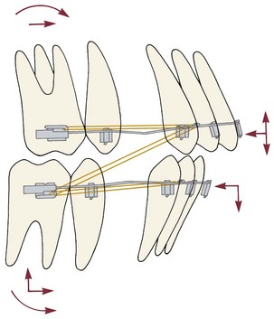
FIGURE 15-10 Diagrammatic representation of forces encountered in the second stage of Begg treatment, in which base archwires (grey) with anchor bends are combined with intra-arch and Class II elastics (orange). The anchor bends produce bodily forward movement of the molars, but no couples are present on the incisors, so these teeth tip lingually. The anchor bends also depress the incisors and elongate the molars, which is counteracted by the Class II elastics for the upper arch but accentuated by the elastics for the lower.
With the edgewise appliance, the width of the brackets makes it difficult to close space by tipping the crowns as in the Begg approach, but it is possible to structure anchorage so that space closure by retraction of the maxillary anterior teeth and protraction of the mandibular posterior segments occurs without the use of Class II elastics. The best control is achieved with the segmented arch technique, using space-closing springs in each arch fabricated specifically for the type of space closure desired (see closure of extraction spaces in this chapter).
A more common approach with the edgewise appliance is to extract maxillary first and mandibular second premolars, thus altering the anchorage value of the two segments (Figure 15-11). With this approach, routine space-closing mechanics will move the lower molars forward more than the upper, particularly if maxillary posterior anchorage is reinforced with a stabilizing lingual arch or headgear. This upper first–lower second premolar extraction pattern greatly simplifies the mechanics needed for differential space closure with continuous-arch edgewise technique.
FIGURE 15-11 Cephalometric superimposition showing the result of treatment with extraction of upper first and lower second premolars. Even with second premolar extraction, some retraction of the mandibular incisors may occur, but most of the space closure will be by mesial movement of the lower molar. This adult patient experienced no growth, and a slight downward and backward rotation of the mandible occurred.
Occasionally, however, mesial movement of the lower first molar into a second premolar extraction space is difficult to produce. This is particularly likely when the second premolar was congenitally missing and a second primary molar is to be extracted because bone resorption reduces the alveolar ridge dimensions before space closure can be completed. It can be advantageous to remove only the distal root of the second primary molar, leaving the mesial part of the primary tooth in place (with a calcium hydroxide pulpotomy and temporary restoration) until the permanent tooth has been brought forward for that half of the total distance. Then the remaining half of the primary tooth is extracted, and space closure completed.12
Molar Correction with Interarch Elastics
Without extraction spaces, Class II elastics produce molar correction largely by mesial movement of the mandibular arch, with only a small amount of distal positioning of the maxillary arch, and can produce far too much protrusion of lower incisors (Figure 15-12). When some forward movement of the mandibular dentition is desired, the amount of force varies with the amount of tipping that is allowed. With a well-fitting rectangular wire in the lower arch, approximately 250 gm per side is needed to displace one arch relative to the other. With a lighter round wire in the lower arch, not more than half that amount of force should be used. Incorporating the lower second molars in the appliance and attaching the elastics to a mesial hook on this tooth increase the anchorage and give a more horizontal direction of pull than hooking the elastic to the first molar.
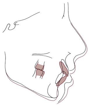
FIGURE 15-12 Cephalometric superimposition showing the response to Class II elastics in a girl in whom this was the major method for correcting a Class II malocclusion. Note that with rectangular archwires, some torque of the upper incisors was obtained. The rotational effects often associated with Class II elastics were less apparent for this patient than is sometimes the case (see also Figure 15-1), but the considerably greater forward displacement of the lower teeth than retraction of the upper teeth is typical. This amount of lower incisor protrusion is undesirable because of both the lip protrusion and lack of stability without permanent retention.
It is important to keep in mind that with or without extraction, Class II elastics produce not only anteroposterior and transverse effects but also a vertical force (Figure 15-13). This force elongates the mandibular molars and the maxillary incisors, rotating the occlusal plane up posteriorly and down anteriorly. If the molars extrude more than the ramus grows vertically, the mandible itself will be rotated downward (see Figure 15-12). Class II elastics therefore are contraindicated in nongrowing patients who cannot tolerate some downward and backward rotation of the mandible. The rotation of the occlusal plane, in and of itself, facilitates the desired correction of the posterior occlusion, but even if elongation of the lower molars can be tolerated because of good growth, the corresponding extrusion of the maxillary incisors can be unsightly.
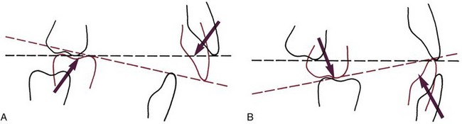
FIGURE 15-13 Rotation of the occlusal plane with Class II (A) and Class III (B) elastics. The rotation of the occlusal plane helps correct the molar relationship, but it can be deleterious in some patients because elongation of the molars may cause undesirable rotation of the mandible or undesirable tooth–lip relationships.
Class II elastics, in short, may produce occlusal relationships that look good on dental casts but are less satisfactory when skeletal relationships and facial esthetics are considered. Because of this, applying heavy Class II force for 9 to 12 months as the major method for correcting a Class II malocclusion is rarely good treatment. Using Class II elastics for 3 or 4 months at the completion of treatment of a Class II patient to obtain good posterior interdigitation, however, is often acceptable.
Class III Camouflage
Class III elastics also have a significant extrusive component, tending to elongate the upper molars and the lower incisors (see Fig 15-13, B). Elongating the molars enough to rotate the mandible downward and backward is disastrous in Class II treatment but, within limits, can help treatment of a Class III problem.
Class III camouflage would be based on a combination of retraction of lower incisors and forward movement of maxillary incisors and, of course, would be successful only if the malocclusion was corrected without harming the facial appearance. As we have noted previously, retracting the lower incisors is likely to make the chin look more, not less, prominent. For this reason, the reverse of the most popular approach to Class II camouflage, extraction of mandibular first and maxillary second premolars with use of Class III elastics, rarely is a good idea for patients of European descent, who rarely have mandibular dental protrusion and often cannot tolerate the increased anterior face height that Class III elastics tend to create. It may be satisfactory in Asian patients, who often do have protrusion of lower incisors relative to the mandible and also are more likely to better tolerate down-back rotation of the mandible.
A better approach to camouflage in patients of European descent with a moderately severe Class III problem is extraction of one lower incisor, which prevents major retraction of the lower teeth, while the maxillary incisors are moved facially with some tipping allowed. The combination of upright mandibular incisors and proclined maxillary incisors often leads to good dental occlusion rather than the expected tooth-size problem, but a setup always should be done when one lower incisor extraction is considered to verify the probably occlusal outcome.
For Asian (or rarely, other) Class III patients with major protrusion of the lower incisors, using skeletal anchorage to move the whole lower arch posteriorly can be quite helpful in correcting the problem (see Figure 18-48). Extraction of third molars usually is needed in order to move the mandibular dental arch back. If second molars are extracted to facilitate distal movement, third molars may erupt as satisfactory replacements, but this is not as likely as in the maxillary arch and therefore is not recommended as a routine procedure.
Class I Crowding/Protrusion: Closure of Extraction Spaces
To obtain the desired result of closing spaces within the arch, it is essential to control the amount of incisor retraction versus molar–premolar protraction. The biomechanical concepts related to control of posterior anchorage and the amount of incisor retraction are described in Chapter 10. In this section, the focus is on contemporary mechanotherapy for space closure with the 18- and 22-slot edgewise appliances.
Moderate Anchorage Situations
Most patients fall into the moderate anchorage category, meaning that after alignment of the incisors to correct crowding has been completed, it is desired to close the remainder of the premolar extraction space with a 50 : 50 or 60 : 40 ratio of anterior retraction to posterior protraction. The different wire sizes in 18- and 22-slot edgewise appliances require a different approach to mechanotherapy.
Moderate Anchorage Treatment with 18-Slot Edgewise: Closing Loops
Although either sliding or loop mechanics can be used, the 18-slot appliance with single or narrow twin brackets on canines and premolars is ideally suited for use of closing loops in continuous archwires. Closing loop archwires should be fabricated from rectangular wire to prevent the wire from rolling in the bracket slots. Appropriate closing loops in a continuous archwire will produce approximately 60 : 40 closure of the extraction space if only the second premolar and first molar are included in the anchorage unit and some uprighting (distal tipping) of the incisors is allowed. Greater retraction will be obtained if the second molar is part of the anchorage unit, less if incisor torque is required.
The performance of a closing loop, from the perspective of engineering theory, is determined by three major characteristics: its spring properties (i.e., the amount of force it delivers and the way the force changes as the teeth move); the moment it generates, so that root position can be controlled; and its location relative to adjacent brackets (i.e., the extent to which it serves as a symmetric or asymmetric bend in the archwire). In addition, clinical performance is affected by how well the loop conforms to additional design principles. Let us consider these in turn:
Spring Properties: The spring properties of a closing loop are determined almost totally by the wire material (at present, either steel or beta-Ti), the size of the wire, and the distance between points of attachment. This distance in turn is largely determined by the amount of wire incorporated into the loop but is affected also by the distance between brackets. Closing loops with equivalent properties can be produced from different types and sizes of wire by increasing the amount of wire incorporated into the loop as the size of the wire increases and vice versa. Wires of greater inherent springiness or smaller cross-sectional area allow the use of simpler loop designs.
Figure 15-14, taken from the work of Booth with steel wires,13 illustrates the effects on the spring characteristics of a steel closing loop from changing wire size, the design of the loop, and the interbracket span (the combination of these latter two parameters, of course, determines the amount of wire in the loop). Note that, as expected, changing the size of the wire produces the largest changes in characteristics, but the amount of wire incorporated in the loop is also important. The same relative effect would be observed with beta-Ti wire. For any size of wire or design of loop, beta-Ti would produce a significantly smaller force than steel.
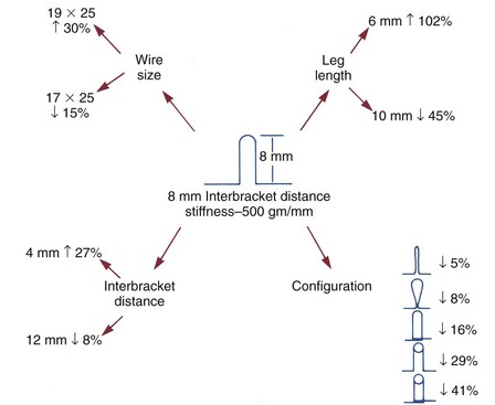
FIGURE 15-14 The effect of changing various aspects of a closing loop in an archwire. Note that an 8 mm vertical loop in 19 × 25 wire produces twice as much force as the desired 250 gm per mm activation. The major possibilities for producing clinically satisfactory loops are reducing wire size or incorporating additional wire by changing leg length, interbracket distance, and/or loop configuration. (Redrawn from Booth FA. MS Thesis: Optimum Forces with Orthodontic Loops. Houston: University of Texas Dental Branch; 1971.)
Root-Paralleling Moments: To close an extraction space while producing bodily tooth movement, a closing loop must generate not only a closing force but also appropriate moments to bring the root apices together at the extraction site. As we have discussed in Chapter 9, for bodily movement, the moment of the force used to move the teeth must be balanced by the moment of a couple. If the center of resistance of the tooth is 10 mm from the bracket, a canine tooth being retracted with a 100 gm force must also receive a 1000 gm-mm moment if it is to move bodily. If the bracket is 1 mm wide, a vertical force of 1000 gm must be produced by the archwire at each side of the bracket.
This requirement to generate a movement limits the amount of wire that can be incorporated to make a closing loop springier because, if the loop becomes too flexible, it will be unable to generate the necessary moments even though the retraction force characteristics are satisfactory. Loop design is also affected. Placing some of the wire within the closing loop in a horizontal rather than vertical direction improves its ability to deliver the moments needed to prevent tipping. Because of this and because a vertically tall loop can impinge on soft tissue, a closing loop that is only 7 to 8 mm tall while incorporating 10 to 12 mm or more of wire (e.g., a delta-, L-, or T-shaped loop) is preferred.
If the legs of a closing loop were parallel before activation, opening the loop would place them at an angle that in itself would generate a moment in the desired direction. Calculations show that unacceptably tall loops would be required to generate appropriate moments in this manner,14 so additional moments must be generated by gable bends (or their equivalent) when the loop is placed in the mouth. An elegant solution to the design of a closing loop that would provide optimum and nearly constant moment-to-force ratios at variable activations was offered by Siatkowski in his Opus loop (Figure 15-15).15
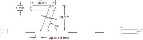
FIGURE 15-15 The Opus closing loop designed by Siatkowski offers excellent control of forces and moments, so that space can be closed under good control. The loop can be fabricated from 16 × 22 or 18 × 25 steel wire or from 17 × 25 TMA wire. It is activated by tightening it distally behind the molar tube and can be adjusted to produce maximal, moderate, or minimal incisor retraction, but like all closing mechanisms with a long range of action, it must be monitored carefully. (Redrawn from Siatkowski RE. Am J Orthod Dentofac Orthop 112:393-402, 484-495, 1997.)
Location of the Loop: A final engineering factor in the performance of a closing loop is its location along the span of wire between adjacent brackets. Because of its gable bends, the closing loop functions as a V-bend in the archwire, and the effect of a V-bend is quite sensitive to its position. Only if it is in the center of the span does a V-bend produce equal forces and couples on the adjacent teeth (see Figures 9-40 and 9-41). If it is one-third of the way between adjacent brackets, the tooth closer to the loop will be extruded and will feel a considerable moment to bring the root toward the V-bend, while the tooth farther away will receive an intrusive force but no moment.16 If the V-bend or loop is closer to one bracket than one-third of the distance, the more distant tooth will not be intruded but will receive a moment to move the root away from the V-bend (which almost never is desirable).
For routine use with fail-safe closing loops (as described later), the preferred location for a closing loop is at the spot that will be the center of the embrasure when the space is closed (Figure 15-16). This means that in a first premolar extraction situation the closing loop should be placed about 5 mm distal to the center of the canine tooth. The effect is to place the loop initially at the one-third position relative to the canine. The moment on the premolar increases as space closure proceeds. This is not ideal for maximum anchorage but is unavoidable with a loop in a continuous archwire. The design of the Opus loop calls for an off-center position with the loop 1.5 mm from the mesial (canine) bracket, which makes it more efficient than the simple loop design but more difficult to manage clinically.
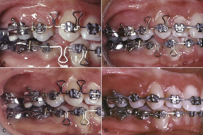
FIGURE 15-16 Space closure with preformed closing loops in the 18-slot appliance. A, 16 × 22 closing loops at initial activation, after the completion of stage 1 alignment and leveling. Note the location of the closing loops and the soldered tiebacks for activation. B, Three months later. C, Spaces closed at 4 months. D, 17 × 25 beta-Ti wire to begin the finishing phase of treatment.
Additional Design Principles: An important principle in closing loop design is that, to the greatest extent possible, the loop should “fail safe.” This means that, although a reasonable range of action is desired from each activation, tooth movement should stop after a prescribed range of movement, even if the patient does not return for a scheduled adjustment. Too long a range of action with too much flexibility could produce disastrous effects if a distorted spring were combined with a series of broken appointments. The ideal loop design therefore would deliver a continuous, controlled force designed to produce tooth movement at a rate of approximately 1 mm per month but would not include more than 2 mm of range, so that movement would stop if the patient missed a second consecutive monthly appointment.
It also is important that the design be as simple as possible because more complex configurations are less comfortable for patients, more difficult to fabricate clinically, and more prone to breakage or distortion. Engineering analysis, as the Opus loop demonstrates very nicely, shows that a relatively complex design is required to produce the best control of moment–force ratios. The possibilities of clinical problems from increased complexity always must be balanced against the potentially greater efficiency of the more complex design. The Opus loop has not been widely adopted because of concerns about its complexity and sturdiness. Clinical experience suggests that the average adolescent orthodontic patient can—and probably will—destroy almost any orthodontic device that is not remarkably resistant to being distorted.
A third design factor relates to whether a loop is activated by opening or closing. All else being equal, a loop is more effective when it is closed rather than opened during its activation. On the other hand, a loop designed to be opened can be made so that when it closes completely, the vertical legs come into contact, effectively preventing further movement and producing the desired fail-safe effect (Figure 15-17). A loop activated by closing, in contrast, must have its vertical legs overlap. This creates a transverse step, and the archwire does not develop the same rigidity when it is deactivated. The smaller and more flexible the wire from which a closing loop arch is made, the more important it is that the wire become rigid when the loop is deactivated.
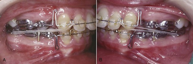
FIGURE 15-17 A and B, Closing loops in 16 × 22 wire of fail-safe design and 8 mm height, used with Class II elastics in this patient. Note that the maxillary loop has been activated by pulling the wire through the molar tube and bending it up. In the mandibular arch, the loop is not active at this time, and the approximation of the legs to create a rigid archwire is apparent. The lower archwire has a tieback mesial to the first molar, so that this loop can be activated by tying a ligature from the posterior teeth to the wire rather than by bending over the end of the wire distal to the molar tube.
Clinical Recommendations: These design considerations indicate that an excellent closing loop for 18-slot edgewise is a delta-shaped loop in 16 × 22 steel wire that is activated by opening, as shown in Figure 15-17. Such a wire fits tightly enough in an 18 × 25 mil bracket to give good control of root position. With 10 mm of wire in the loop, the force delivery is close to the optimum, and the mechanism fails safe because contact of the vertical legs when the loop is deactivated limits movement between adjustments and makes the archwire more rigid. It is important to activate the upper horizontal portion of a delta or T-loop so that the vertical legs are pressed lightly together when the loop is not activated (Figure 15-18). This also ensures that the loop will still be active until the legs come into contact.
FIGURE 15-18 A three-prong pliers can be used to bring the vertical legs of a closing loop together if they are separated. The legs should touch lightly before activation of the loop by opening it.
With 16 × 22 wire and a loop of the delta design (so that the mechanism fails safe), with an activation of 1.0 to 1.5 mm, and with narrow 18-slot brackets, a gable bend of approximately 20 degrees on each side is needed to achieve an appropriate ratio between the moment of the couple and the moment of the force (MC/MF ratio) (Figure 15-19). With wider brackets, a smaller gable bend would generate the same moment. With the same loop in stiffer wire like 17 × 25, a gable bend of any given magnitude would produce a larger moment than in 16 × 22 wire. Remember, however, that the MC/MF ratio determines how teeth will move, so with a stiffer wire and the same activation a larger force would be generated and a larger moment would be needed. Optimum moment–force ratios can be achieved with several combinations of wire size, loop configuration, and gable angle and, as Siatkowski has shown, can be maintained over a variety of activations at the cost of design complexity.
FIGURE 15-19 Gable bends for the closing loop archwire. A, Gable bends are placed by bending the wire at the base of the loop. B, Appropriate gable for a 16 × 22 closing loop (40 to 45 degrees total, half that on each side).
A closing loop archwire is activated by pulling the posterior part of the archwire distally through the molar tubes, which activates the closing loop the desired amount (1 to 1.5 mm) and then fastening the wire in that position. The wire slides through the brackets and tubes only when it is being activated. After that, as the closing loop returns to its original configuration, the teeth move with the archwire, not along it, so there is no resistance to sliding. There are two ways to hold the archwire in its activated position. The simplest is by bending the end of the archwire gingivally behind the last molar tube. The alternative is to place an attachment—usually a soldered tieback (see Figure 15-16) on the posterior part of the archwire, so that a ligature can be used to tie the wire in its activated position.
With a 16 × 22 closing loop, usually it is necessary to remove the archwire and reactivate the gable bends after 3 to 4 mm of space closure, but a quick reactivation is all that is needed at most appointments during space closure. As a general rule, if it is anticipated that a closing loop archwire will not have to be removed for adjustment (i.e., the distance to be closed is 4 mm or less), bending the posterior end of the wire is satisfactory. It can be quite difficult to remove an archwire that has been activated by bending over the end, however, and it saves time in the long run to use tiebacks for closing loop archwires that will have to be removed and readjusted.
Specific recommendations for closing loop archwires with the 18-slot appliance and narrow brackets are:
1. 16 × 22 wire, delta or T-shaped loops, 7 mm vertical height, and additional wire incorporated into the horizontal part of the loop to make it equivalent to 10 mm of vertical height.
2. Gable bends of 40 to 45 degrees total (half on each side of the loop).
3. Loop placement 4 to 5 mm distal to the center of the canine tooth, at the center of the space between the canine and second premolar with the extraction site closed.
These recommendations certainly are not the only clinically effective possibilities. The principle should be that if a heavier wire (e.g., 17 × 25 mil) is used, the loop design should be altered to incorporate additional wire for better force-deflection characteristics. Also, the gable angulations should be adjusted according to both the springiness of the loop and the width of the brackets. With wide brackets on the canines, for instance, the reduced interbracket span would make any loop somewhat stiffer, and both this and the longer moment arm across the bracket would dictate a smaller gable angle, but the range of the loop would be reduced, which is why wide brackets are not recommended when closing loops are to be used.
Moderate Anchorage Space Closure with 22-Slot Edgewise
As a general rule, space closure in moderate anchorage situations with the 22-slot edgewise appliance is done in two steps to better control posterior anchorage: first retracting the canines, usually sliding them along the archwire, and second, retracting the four incisors, usually with a closing loop. This will produce an approximately 60 : 40 closure of the extraction space, varying somewhat depending on whether second molars are included in posterior anchorage and incisor torque requirement, which is the same ratio as one-step closure with a closing loop. En masse sliding leads to 50 : 50 closure at best, even with bi-dimensional wires that are smaller posteriorly in an effort to avoid friction (but does not avoid binding).
A 19 × 25 wire is the largest on which sliding retraction of a canine should be attempted (because clearance in the bracket slot is needed), and 18 × 25 wire also can be used. An archwire with a posterior stop, usually in front of the first molar tube, is needed. This stop has the effect of incorporating all the teeth except the canine into the anchorage unit. The canine retraction can then be carried out with a coil spring, a spring soldered to the base archwire or an elastomeric material. As a general rule, A-NiTi coil springs are preferred because they produce an almost ideal light constant force (Figure 15-20). Both elastomeric chains and steel coil springs produce rapidly decaying interrupted forces.
FIGURE 15-20 In this patient with a 22-slot appliance, sliding space closure in the lower arch is being carried out with a NiTi coil spring, while a segmental closing loop is being used in the upper arch for retraction of the canine. Note that the base archwire bypasses the canine.
In addition to its convenience and straightforward design, this type of sliding space closure has the important advantage that it fails safe in two ways:
1. The moments necessary for root paralleling are generated automatically by the twin brackets normally used with the 22-slot appliance. Unless the archwire itself bends, there is no danger that the teeth will tip excessively (Figure 15-21).
FIGURE 15-21 A, When a retraction force is placed on the brackets (blue arrows), the center of resistance feels both a translational force and the moment of a force that initially causes tipping (red arrows). B, As the teeth tip, the wire engages at opposite edges of the bracket, creating a couple that resists tipping. After a certain level of tipping occurs, the moment of the couple and the moment of a force are in equilibrium and no further tipping occurs. This equilibrium point depends on the retraction force, wire stiffness, interbracket span, and bracket width.
2. The rigid attachment of the canine to the continuous ideal archwire removes the danger that this tooth will be moved far outside its intended path if the patient does not return for scheduled adjustments. For this reason, a long range of action on the retraction springs is not dangerous, as long as the force is not excessive. The ideal force to slide a canine distally is 150 to 200 gm, since at least 50 to 100 gm will be used to overcome binding and friction (see Chapter 9). A-NiTi springs can produce this level of force over a wide enough range to close an extraction space with a single activation.
The second stage in the two-stage retraction is usually accomplished with a closing loop, although it is possible to close the space now located mesial to the canines by again sliding the archwire through the posterior brackets. For this stage of incisor retraction, a rectangular wire with its smallest side at least 18 mil is needed—anything smaller rolls in the 22-slot and would allow the incisors to tip while being retracted. An 18 × 25 steel wire with a T-loop, though still too stiff, serves this purpose reasonably well while retaining the fail-safe design. Although loops in a 19 × 25 steel wire also can be used, the better force-deflection characteristics of 18 × 25 wire make it the preferred choice: the 19 × 25 loop either has to give up the fail-safe design or is much too stiff. A third alternative, in many ways now the preferred approach, is a closing loop in 19 × 25 beta-Ti wire. This provides better properties than 18 × 25 steel (quite close to 16 × 22 steel) at the cost of more difficulty in forming the archwire.
Although the two-step procedure is predictable and has excellent fail-safe characteristics, which explains why it remains commonly used, it takes longer to close space in two steps than one. It is possible to use a closing loop archwire for one-step (en masse) closure in the 22-slot appliance, as described previously for 18-slot edgewise. There are several possibilities, unfortunately none of them ideal. The Opus loop has excellent properties and can be used with 22-slot edgewise but is more effective in 18-slot because of the wire size. If a fail-safe design is preferred, a T-loop in 18 × 25 steel or 19 × 25 beta-Ti wire can be considered. All three of these possibilities provide less than ideal torque control of incisors during the retraction because the wire is so much smaller than the bracket slot. If en masse space closure is desired with the 22-slot appliance, a segmented arch technique offers advantages.
The segmented arch approach to space closure17 is based on incorporating the anterior teeth into a single segment, and both the right and left posterior teeth also into a single segment, with the two sides connected by a stabilizing lingual arch. A retraction spring (Figure 15-22) is used to connect these stable bases, and the activation of the spring is varied to produce the desired pattern of space closure. Because the spring is separate from the wire sections that engage the bracket slots, a wire size and design that produce optimum properties can be used. An auxiliary rectangular tube, usually positioned vertically, is needed on the canine bracket or on the anterior wire segment to provide an attachment for the retraction springs. The posterior end of each spring fits into the auxiliary tube on the first molar tooth. With beta-Ti wire, the design of the retraction spring can be more simplified than the design necessary with steel wire. These springs are very effective, and with careful initial activation, an impressive range of movement can be produced before reactivation is necessary.
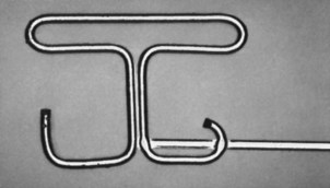
FIGURE 15-22 Composite retraction spring designed by Burstone for use with the segmented arch technique, consisting of 18 mil beta-Ti wire (the loop) welded to 17 × 25 beta-Ti. This spring can be used either for en masse retraction of incisors or canine retraction.
The greatest disadvantage of segmented arch space closure is not its increased complexity but that it does not fail safe. Without a rigid connection between the anterior and posterior segments, there is nothing to maintain arch form and proper vertical relationships if a retraction spring is distorted or activated incorrectly. For this reason, despite the excellent results usually obtained with segmented arches and retraction springs, it is important to monitor these patients especially carefully and to avoid long intervals without observation.
Maximum Incisor Retraction (Maximum Anchorage)
Techniques to produce maximum retraction combine two possible approaches. The first is reinforcement of posterior anchorage by appropriate means, including extraoral force, stabilizing lingual arches, interarch elastics, and, more recently, skeletal anchorage (indicated only if an extremely severe protrusion problem exists). The second approach involves reduction of strain on the posterior anchorage, which includes any combination of eliminating resistance to sliding from the retraction system (as with closing loops), tipping the incisors and later uprighting them (as in Begg technique), or retracting the canines separately (as in Tweed technique).
Maximum Retraction with the 18-Slot Appliance
With the 18-slot appliance, binding during sliding usually is avoided by employing closing loops, and tipping/uprighting is rarely part of the anchorage-control strategy. To obtain greater retraction of the anterior teeth, a sequence of steps to augment anchorage and reduce anchorage strain could be as follows:
1. Add stabilizing lingual arches and proceed with en masse space closure. The resulting increase in posterior anchorage, though modest, will change the ratio of anterior retraction to posterior protraction to approximately 2 : 1.
2. Reinforce maxillary posterior anchorage with extraoral force and (if needed) use Class III elastics from high-pull headgear to supplement retraction force in the lower arch, while continuing the basic en masse closure approach. Depending on how well the patient cooperates, additional improvement of retraction, perhaps to a 3 : 1 or 4 : 1 ratio, can be achieved.
3. Retract the canines independently, preferably using a segmental closing loop, and then retract the incisors with a second closing loop archwire. Used with stabilizing lingual arches (which are needed to control the posterior segments in most patients), this technique will produce a 3 : 1 retraction ratio, but the added complexity and increased treatment time of this two-step method makes skeletal anchorage a more practical approach.
4. Use bone screws to stabilize the posterior segments. This is the ultimate reinforcement of anchorage, and it now is used to avoid two-step space closure.
A more detailed discussion of each of these approaches follows.
Reinforcement with Stabilizing Lingual Arches: Stabilizing lingual arches must be rigid and should be made from 36 mil or 32 × 32 steel wire. These can be soldered to the molar bands, but it is convenient to be able to remove them, and Burstone’s designs (see Chapter 10) are preferred.
It is important for a lower stabilizing lingual arch to lie behind and below the lower incisors, so that it does not interfere with their retraction. If 36 mil round wire is used, the lower lingual arch is more conveniently inserted from the distal than from the mesial of the molar tube. The maxillary stabilizing lingual arch is a straight transpalatal design. Because maximum rigidity is desired for anchorage reinforcement, an expansion loop in the palatal section of this wire is not recommended unless a specific indication exists for including it.
If lingual arches are needed for anchorage control, they should be present during the first and second stages of treatment but can and should be removed after space closure is complete. Their presence during the finishing stage of treatment, after extraction spaces have been closed, is not helpful and may interfere with final settling of the occlusion.
Reinforcement with Headgear and Interarch Elastics: Extraoral force against the maxillary posterior segments is an obvious and direct method for anchorage reinforcement. It is also possible to place extraoral force against the mandibular posterior segments but is usually more practical to use Class III elastics to transfer the extraoral force from the upper to the lower arch.
Interarch elastics for anchorage reinforcement were a prominent part of the original Tweed method for maximum retraction of protruding anterior teeth. In the Tweed approach to bimaxillary protrusion, “anchorage preparation,” achieved by tipping the molars and premolars distally, was done before space closure. As anchorage was being prepared in the lower arch, Class III elastics were used to maintain lower incisor position while this is done. After the lower incisors were retracted, sliding the canine initially and then using a closing loop, the lower arch was stabilized and Class II elastics were used to prepare anchorage by tipping back the upper molars, before the upper incisors were retracted.
Although the original Tweed approach can be used with the contemporary 18-slot appliance, it is rarely indicated. Prolonged use of Class II and Class III elastics is extrusive and requires good vertical growth for acceptable results. Distally tipping the molars augments their anchorage value primarily by first moving these teeth distally, then mesially.
Segmented Retraction of the Canines: Individualized retraction of the canines with segmented closing loops is an attractive method for reducing the strain on posterior anchorage and is a readily available approach with the modern 18-slot appliance. It is also possible to retract the canines by sliding them on the archwire, but the narrow brackets usually used with the 18-slot appliance and the tight clearance and relatively low strength of a 17 × 25 archwire produce less-than-optimum sliding.
For use of segmented closing loops, an auxiliary tube on the molar is needed. An auxiliary tube on the canine is unnecessary because the retraction spring can fit directly into the canine bracket. The PG spring designed by Gjessing is an efficient current design (Figure 15-23),18 but is somewhat complex to fabricate and activate. After the canine retraction, closing loops, either in a continuous archwire or with a segmented arch approach, are then used for the second stage of retraction of the incisors.
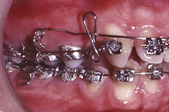
FIGURE 15-23 For canine retraction, the Gjessing retraction spring offers excellent control of forces and moments and probably is the most effective current design of a spring for this purpose. In this patient, canine retraction is being done simultaneously with intrusion of the incisor segment.
Segmented canine retraction of this type presents two problems. The first is that it is difficult to control the position of the canine in all three planes of space as it is retracted. If the canine is pulled distally from an attachment on its buccal surface, the point of attachment is not only some distance occlusal but is also buccal to the center of resistance. This means that without appropriate moments, the tooth will tip distally and rotate mesiobuccally. Both a root-paralleling moment and an antirotation moment must be obtained by placing two different gable bends in the same spring. Control of the vertical position of the canine, particularly after the gable bends in two planes of space have been placed, can be a significant problem.
Second, much more than with en masse retraction using segmented mechanics, segmental retraction of canines does not fail safe. The canine is free to move in three-dimensional space, and there are no stops to prevent excessive movement in the wrong direction if a spring is improperly adjusted or becomes distorted. Loss of vertical control is particularly likely. A missed appointment and a distorted spring can lead to the development of a considerable problem, and patients must be monitored carefully.
Retraction with Skeletal Anchorage: Skeletal anchorage for retraction of protruding incisors is most easily accomplished by placing a bone screw in the dental alveolus between the second premolar and first molar (see Figure 10-48). Using the bone screw to stabilize the posterior segment (indirect anchorage) while closing the extraction space with loop mechanics is preferred, especially if the 18-slot appliance is used. The closing loop would be designed and activated as described above.
Maximum Retraction with the 22-Slot Appliance
The same basic approaches are available with the 22-slot appliance as with the 18-slot appliance: to increase the amount of incisor retraction, a combination of increased reinforcement of posterior anchorage and decreased strain on that anchorage is needed. All the possible strategies for anchorage control can be used, but skeletal anchorage greatly simplifies the situation and makes it possible to close the space with en masse movement of the anterior teeth rather than retracting the canine separately.
Reinforcement of posterior anchorage with a stabilizing arch is a necessity when maximum retraction is desired and skeletal anchorage is not used. Headgear to reinforce posterior anchorage is possible but is inefficient in comparison, even when cooperation is excellent.19 Although a transpalatal arch anchored with a bone screw in the palate can be used, a bone screw between the second molar and first molar is easier and quite effective. With the 22-slot appliance, sliding along a 19 × 25 steel archwire with an A-NiTi coil spring is the usual approach. Either direct or indirect anchorage can be used. Directly attaching the spring to the bone screw generates an upward and backward direction of pull, while stabilizing the posterior teeth gives a straight back direction (see Figure 10-48). The choice of direct versus indirect anchorage should be based on the desired direction.
Reducing the strain on anchorage by minimizing binding and friction is the other aspect of the maximum retraction approach. A segmented arch system to retract the canines independently, followed by retraction of the four incisors, is a practical method for conserving anchorage and equally adaptable to 22- and 18-slot appliances. The problems are also the same as those reviewed in the 18-slot section: the canine is difficult to control during its retraction, especially the vertical position, and because no fail-safe mechanism is in place, it may become spectacularly malpositioned if something goes wrong.
For this reason, rather than independent retraction of the canines to conserve anchorage, the recommended procedure in two-step space closure in 22-slot maximum anchorage cases now is en masse distal tipping of the anterior teeth, followed by uprighting.20 The segmented arch technique is used, but the spring assembly is activated differently from the one needed for space closure in moderate retraction cases. Compared with independent retraction of the canines with loops, the fail-safe characteristics of this approach are much improved (though still not as good as with continuous archwires). It is now more efficient to use bone screws when maximum retraction is desired.
Minimum Incisor Retraction
As with any problem requiring anchorage control, the approaches to reducing the amount of incisor retraction involve reinforcement of anchorage (the anterior teeth in this situation) and reduction of strain on that anchorage. An obvious strategy, implemented at the treatment planning stage, is to incorporate as many teeth in the anterior anchor unit as possible. Therefore if extraction of teeth is necessary at all, extracting a second premolar or molar—not a first premolar—is desirable. All other factors being equal, the amount of incisor retraction will be less the further posteriorly in the arch an extraction space is located.
A second possibility for reinforcing incisor anchorage is to place active lingual root torque in the incisor section of the archwires, maintaining a more mesial position of the incisor crowns at the expense of somewhat greater retraction of the root apices (Figure 15-24). In patients in whom it is desired to close extraction sites by moving the posterior teeth forward, the incisors are often already upright, and lingual root torque is likely to be desired for both esthetic reasons and control of anchorage. Burstone’s segmented arch technique can be used to particular advantage when this strategy for producing differential forward movement of posterior teeth is used.
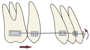
FIGURE 15-24 Torque forces against the incisors create a crown-forward, as well as a root-backward, tendency. Preventing the incisor crowns from tipping forward tends to pull the posterior teeth forward, which can be advantageous if it is desired to close space in this way.
A third possibility for maximizing forward movement of posterior teeth is to break down the posterior anchorage, moving the posterior teeth forward one tooth at a time. After extraction of a second premolar, for example, it may be desired to stabilize the eight anterior teeth and to bring the first molars forward independently, creating a space between them and the second molars before bringing the second molars anteriorly. This strategy can readily be combined with increased torque of the anterior teeth to minimize retraction.
Skeletal anchorage, created by placing a bone screws in either arch in the canine region, is the easiest and most effective way to close an extraction space by bringing posterior teeth forward (Figure 15-25; see also Figure 18-49). It is particularly advantageous when more forward movement is needed on one side than the other (Figure 15-26). In both minimum and maximum retraction, TADs now make it much easier to handle what previously were very difficult situations.
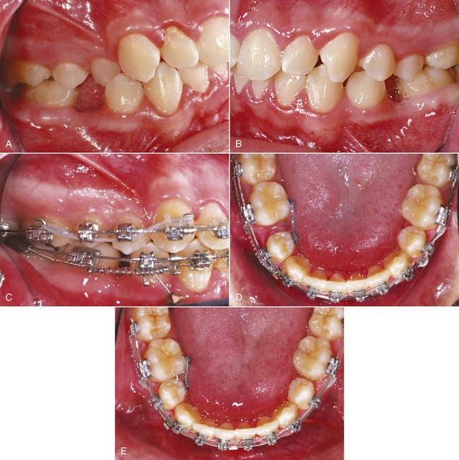
FIGURE 15-25 A and B, For this patient, a goal of treatment was closure of the space where mandibular second premolars were missing by bringing the mandibular molars forward, with more movement needed on the right side. C, A bone screw was placed in the dentoalveolar process between the right central and lateral incisors, and those teeth were stabilized by tying them to the archwire (indirect anchorage), and then the spaces were closed with sliding mechanics (D and E). (Courtesy Dr. N. Scheffler.)
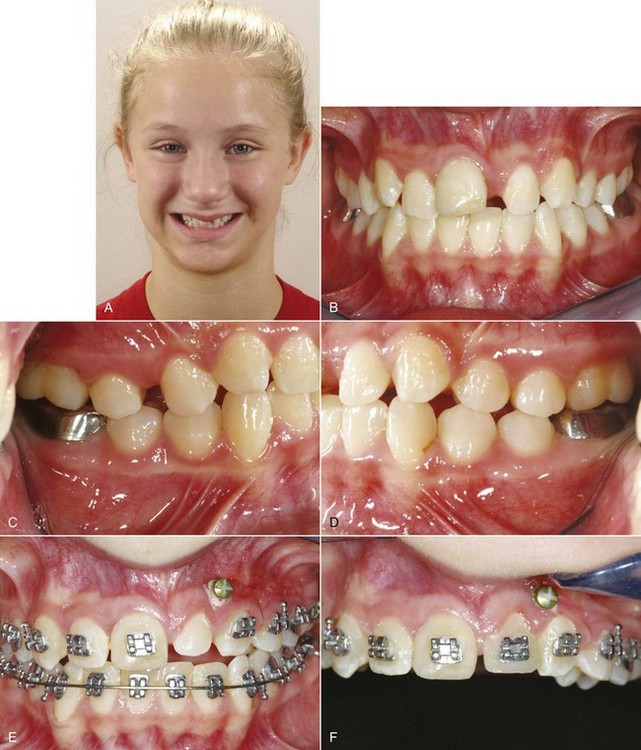
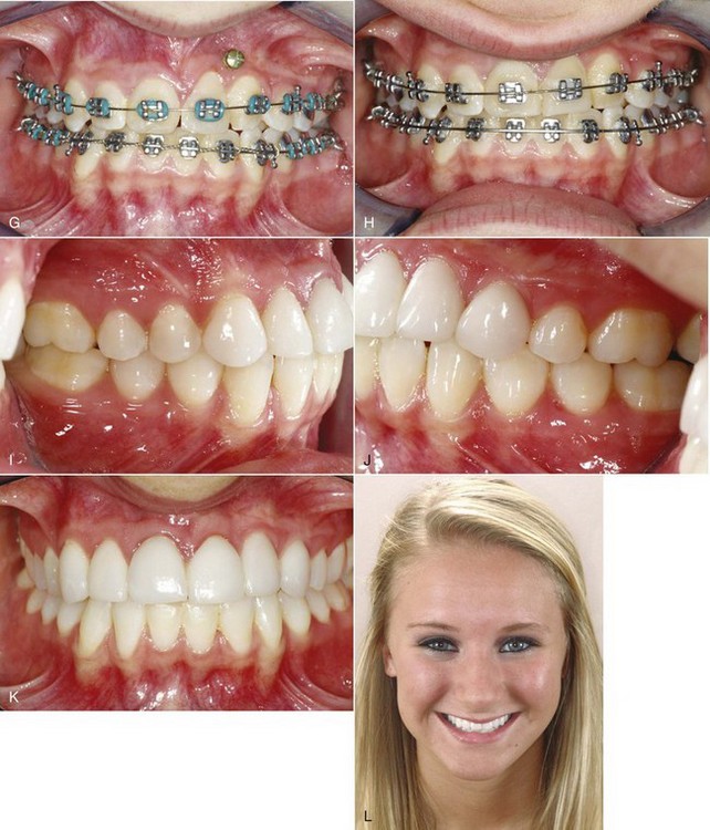
FIGURE 15-26 A, This girl lost her maxillary left central incisor to trauma at age 8, and by the time she was seen by the orthodontist at age 11, the left lateral incisor had moved mesially into the central incisor space. B to D, Intraoral views at age 11. The treatment plan was to use the lateral incisor as a replacement for the central incisor, intruding it to allow leveling of the gingival margin with the right central, then build it up so that it would be the correct size during the finishing orthodontics, and ultimately use a laminate veneer as part of the final restoration. The canine would be recontoured to make it an acceptable lateral incisor (see Figure 7-30). The canine would be recontoured to make it an acceptable lateral incisor (see Figure 7-30). E, A bone screw was placed between the lateral incisor and canine, above the root apices, as anchorage to bring the left posterior teeth anteriorly. F, When the lateral was in the central spot and a Class II molar relationship had been obtained on the left side, a temporary buildup was done to bring the lateral incisor close to the width desired at the end of treatment, the canine was recontoured to serve as a lateral incisor (see Figure 7-30), and brackets were placed to reposition these teeth. G, When the lateral was in the central spot and a Class II molar relationship had been obtained on the left side, a temporary build-up was done to bring the lateral incisor close to the width desired at the end of treatment, the canine was recontoured to serve as a lateral incisor (see Figure 7-30), and brackets were placed to reposition these teeth. H, The goal was to bring gingival margins to approximately the correct levels for a central and lateral incisor, and then a diode laser was used to refine the gingival contours. I to K, Intraoral views at age 13, after completion of orthodontics and placement of a veneer on the left lateral, and (L) the facial view at that time. She was very pleased with the outcome, but a better smile arc could have been obtained by making the veneer on the lateral slightly longer and slightly elongating the right central (see section on micro-esthetics in Chapter 7).
References
1. Stucki, N, Ingervall, B. The use of the Jasper Jumper for correction of Class II malocclusion in the young permanent dentition. Eur J Orthod. 1998;20:271–281.
2. Patel, MP, Janson, G, Henriques, JF, et al. Comparative distalization effects of Jones jig and pendulum appliances. Am J Orthod Dentofac Orthop. 2009;135:336–342.
3. Wiechmann, D, Schwestka-Polly, R, Pancherz, H, et al. Control of mandibular incisors with the combined Herbst and completely customized lingual appliance—a pilot study. Head Face Med. 11 March 2010;6:3. [posted].
4. Antonarakis, GS, Kiliaridis, S. Maxillary molar distalization with noncompliance intramaxillary appliances in Class II malocclusion. A systematic review. Angle Orthod. 2008;78:1133–1140.
5. Byloff, FK, Darendeliler, MA. Distal molar movement using the pendulum appliance. Part I. Clinical and radiological evaluation. Angle Orthod. 1997;67:249–260.
6. Byloff, FK, Darendeliler, MA, Clar, E, et al. Distal molar movement using the pendulum appliance. Part II. The effects of maxillary molar root uprighting bends. Angle Orthod. 1997;64:261–270.
7. Cornelis, MA, De Clerck, HJ. Maxillary molar distalization with miniplates assessed on digital models: a prospective clinical trial. Am J Orthod Dentofac Orthop. 2007;132:373–377.
8. Onça , G, Seçkin, O, Dinçer, B, et al. Osseointegrated implants with pendulum springs for maxillary molar distalization: a cephalometric study. Am J Orthod Dentofac Orthop. 2007;131:16–26.
9. Moffitt, AH. Eruption and function of maxillary third molars after extraction of second molars. Angle Orthod. 1998;68:147–152.
10. McLaughlin, RP, Bennett, JC. The extraction-nonextraction dilemma as it relates to TMD. Angle Orthod. 1995;65:175–186.
11. Rinchuse, DJ, Rinchuse, DJ, Kandasamy, S. Evidence-based versus experience-based views on occlusion and TMD. Am J Orthod Dentofac Orthop. 2005;127:249–254.
12. Northway, WM. The nuts and bolts of hemisection treatment: managing congenitally missing mandibular second premolars. Am J Orthod Dentofac Orthop. 2005;127:606–610.
13. Booth, FA. MS Thesis: Optimum Forces with Orthodontic Loops. Houston: University of Texas Dental Branch; 1971.
14. Braun, S, Sjursen, RC, Legan, HL. On the management of extraction sites. Am J Orthod Dentofac Orthop. 1997;112:645–655.
15. Siatkowski, RE. Continuous archwire closing loop design, optimization and verification. Parts I and II. Am J Orthod Dentofac Orthop. 1997;112:393–402. [484-495].
16. Ronay, F, Kleinert, W, Melsen, B, et al. Force system developed by V bends in an elastic orthodontic wire. Am J Orthod Dentofac Orthop. 1989;96:295–301.
17. Nanda R, ed. Biomechanics and Esthetic Strategies in Clinical Orthodontics. Philadelphia: Elsevier/Saunders, 2005.
18. Eden, JD, Waters, N. An investigation into the characteristics of the PG canine retraction spring. Am J Orthod Dentofac Orthop. 1994;105:49–60.
19. Li, F, Hu, HK, Chen, JW, et al. Comparison of anchorage capacity between implant and headgear during anterior segment retraction. Angle Orthod. 2011;81:915–922.
20. Shroff, B, Yoon, WM, Lindauer, SJ, et al. Simultaneous intrusion and retraction using a three-piece base arch. Angle Orthod. 1997;67:455–462.