Contemporary Orthodontic Appliances
Orthodontic appliances have evolved steadily since the development of the specialty, but the pace of change has accelerated significantly in recent years. Technologic advances have brought both improvements in existing appliance systems (for instance, new brackets and wires for the edgewise appliance) and new ways of correcting malocclusion (such as clear aligners formed on stereolithographic models and temporary skeletal anchorage). The improved technology has greatly increased the productivity of orthodontists. Charles Tweed suggested in the 1950s that an orthodontist should not start treatment for more than 50 patients per year because there would not be enough time to manage more than that and achieve quality results. This number has greatly increased since then but so has average treatment quality—and comprehensive orthodontic treatment that cost about the same as a new car at that time now costs far less.
At this point, an orthodontist can use a given appliance system to treat most of his or her patients, but for the best patient care, needs to select among appliance systems to fit the needs of individual patients. Modern removable appliances can do some things better than fixed appliances, and variants within fixed appliance systems do some things better than others. The purpose of this chapter is to provide an overview of modern appliances, and put them in perspective in a way that helps in the choice of the best appliance for specific situations—a goal that extends into the clinical chapters that follow.
Removable Appliances
Removable orthodontic appliances have two immediately apparent advantages: (1) they are fabricated in the laboratory and adjusted extraorally rather than directly in the patient’s mouth, reducing the dentist’s chair time, and (2) they can be removed on socially sensitive occasions if wires on the facial part of the teeth would be visible, or can be made almost invisible if fabricated from clear plastic materials. This makes them (at least initially) more acceptable to adult patients. In addition, removables allow some types of growth guidance treatment to be carried out more readily than is possible with fixed appliances. These advantages for both the patient and the dentist have ensured a continuing interest in removable appliances for both children and adults.
There are also two significant disadvantages: (1) the response to treatment is heavily dependent on patient compliance, since the appliance can be effective only when the patient chooses to wear it, and (2) it is difficult to obtain the two-point contacts on teeth necessary to produce complex tooth movements, which means that the appliance itself may limit the possibilities for treatment. Because of these limitations, removable appliances in children are most useful for the first of two phases of treatment, with fixed appliances used in the second phase; and if removable clear aligners are used in treatment of adults, some fixed attachments (which can be relatively small tooth-colored composites rather than brackets) often must be bonded in order to achieve effective tooth movement. For these reasons, contemporary comprehensive treatment for adolescents almost always requires fixed, nonremovable appliances, and clear aligner therapy for adults is evolving toward the use of a combination of aligners and fixed appliances for the more complex cases.
The Development of Removable Appliances
In the United States, the original removable appliances were rather clumsy combinations of vulcanite bases and precious metal or nickel-silver wires. In the early 1900s, George Crozat developed a removable appliance fabricated entirely of precious metal that consisted of an effective clasp for first molar teeth, heavy gold wires as a framework, and lighter gold fingersprings to produce the desired tooth movement (Figure 10-1). The Crozat appliance attracted a small but devoted following, and as the twenty-first century began, a modified version still was being used for comprehensive treatment by a few practitioners. Its limitation is that, like almost all removables, it produces mostly tipping of teeth. It had little impact on the mainstream of American orthodontic thought and practice, however, which from the beginning was focused on fixed appliances.
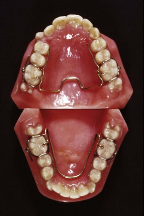
FIGURE 10-1 Crozat appliances for the upper and lower arch, showing the transverse connectors that allow lateral expansion. The Crozat clasps on the molars utilize fingers extending into the mesiobuccal and distobuccal undercuts.
For a variety of reasons, development of removable appliances continued in Europe despite their neglect in the United States. There were three major reasons for this trend: (1) Angle’s dogmatic approach to occlusion, with its emphasis on precise positioning of each tooth, had less impact in Europe than in the United States; (2) social welfare systems developed much more rapidly in Europe, which tended to place the emphasis on limited orthodontic treatment for large numbers of people, often delivered by general practitioners rather than orthodontic specialists; and (3) precious metal for fixed appliances was less available in Europe, both as a consequence of the social systems and because the use of precious metal in dentistry was banned in Nazi Germany. This forced German orthodontists to focus on removable appliances that could be made with available materials. (Precision steel attachments were not available until long after World War II; fixed appliances required precious metal.)
The interesting result was that in the 1925 to 1965 era, American orthodontics was based almost exclusively on the use of fixed appliances (partial or complete banding), while fixed appliances were essentially unknown in Europe and all treatment was done with removables, not only for growth guidance but also for tooth movement of all types.
A major part of European removable appliance orthodontics of this period was functional appliances for guidance of growth. A functional appliance by definition is one that changes the posture of the mandible, holding it open or open and forward. Pressures created by stretch of the muscles and soft tissues are transmitted to the dental and skeletal structures, moving teeth and modifying growth. The monobloc developed by Robin in the early 1900s is generally considered the forerunner of all functional appliances, but the activator developed in Norway by Andresen in the 1920s (Figure 10-2) was the first functional appliance to be widely accepted.
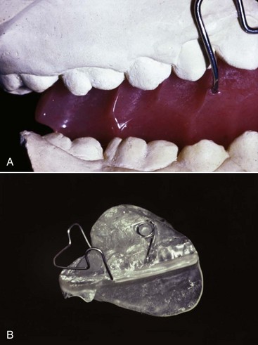
FIGURE 10-2 The Activator, a tooth-borne passive appliance, was the first widely used functional appliance. The appliance opens the bite, and the mandible is advanced for Class II correction. A, In the original Andresen activator, angled flutes in the acrylic were used to guide the path of eruption of the posterior teeth, usually so that the molars moved distally in the upper arch and mesially in the lower arch as the teeth erupted and also to expand the dental arches if desired. B, The lingual flanges of an activator are the mechanism to advance the mandible. In this design, the maxillary posterior teeth are prevented from erupting by the acrylic shelf, while the mandibular posterior teeth are free to erupt; thus the appliance will induce a rotation of the occlusal plane, which usually is desirable in functional appliance treatment because it makes it easier to change a Class II to a Class I molar relationship. This appliance also has displacement springs on the upper first molars, which requires the patient to actively maintain the appliance in the proper position. It was once thought that a loosely-fitting appliance contributed to activation of the mandibular musculature, but research has not supported this concept, so modern activators are more likely to incorporate clasps than displacing springs.
Andresen’s activator became the basis of the “Norwegian system” of treatment. Both the appliance system and its theoretical underpinnings were improved and extended elsewhere in Europe, particularly by the German school led by Haupl, who believed that the only stable tooth movement was produced by natural forces and that alterations in function produced by these appliances would give stable corrections of malocclusion. This philosophic approach was diametrically opposite to that espoused by Angle and his followers in the United States, who emphasized fixed appliances to precisely position the teeth and presumed that if they were in ideal occlusion, that would keep them there. These opposing beliefs contributed to the great differences between European and American orthodontics at mid-twentieth century.
In the European approach at that time, removable appliances often were differentiated into “activators,” or functional appliances aimed at modifying growth, and “active plates” aimed at moving teeth. In addition to the functional appliance pioneers, two European orthodontists deserve special mention for their contributions to removable appliance techniques for moving teeth. Martin Schwarz in Vienna developed and publicized a variety of “split plate” appliances, which were effective for expanding the dental arches (Figure 10-3). Philip Adams in Belfast modified the arrowhead clasp favored by Schwarz into the Adams crib, which became the basis for English removable appliances and is still the most effective clasp for orthodontic purposes (Figure 10-4).
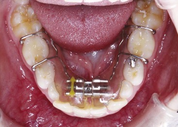
FIGURE 10-3 A removable appliance of the “Schwarz plate” design used a jackscrew to separate the parts of the acrylic plate and expand the dental arch. They can be used in the maxillary or mandibular dental arch—this one is being used to expand across the lower incisors to provide more space for the crowded teeth. Although the force system created by turning a screw is far from ideal, plates of this type can be effective in producing small amounts of tooth movement.
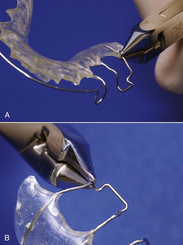
FIGURE 10-4 Clinical adjustments of an Adams clasp. A, Tightening the clasp by bending it gingivally at the point where the wire emerges from the baseplate. This is the usual adjustment for a clasp that has become loose after repeated insertions and removals of an appliance. B, Adjustment of the clasp by bending the retentive points inward. This alternative method of tightening a clasp is particularly useful during the initial fitting of an appliance.
Functional appliances were introduced into American orthodontics in the 1960s through the influence of orthodontic faculty members with a background in Europe (of whom Egil Harvold was prominent) and later from personal contact by a number of American orthodontists with their European counterparts. (Fixed appliances spread to Europe at the same time through similar personal contacts.) A major boost to functional appliance treatment in the United States came from the publication of animal experiment results in the 1970s showing that skeletal changes really could be produced by posturing the mandible to a new position and holding out the possibility that true stimulation of mandibular growth could be achieved (see Chapter 8). Although some of the enthusiasm for functional appliance treatment caused by the favorable animal experiments has faded in the light of less impressive results from clinical trials and retrospective clinical studies (see Chapter 13), functional appliances have achieved a major place in contemporary growth modification treatment.
At this point, the dichotomy between European and American orthodontics has largely disappeared. European-style removable appliances, particularly for growth modification during first-stage mixed dentition treatment, have become widely used in the United States and other countries, while fixed appliances have largely replaced removables for comprehensive treatment in Europe and elsewhere throughout the world.
Modern removable appliance therapy consists largely of the use of (1) various types of functional appliances for growth guidance in adolescents and, less frequently, in children; (2) active plates for tooth movement, used primarily in preadolescents; and (3) clear plastic aligners for tooth movement in adults. The focus of this part of the chapter, accordingly, is on the characteristics of the appliances used for these purposes, especially clear aligner therapy (CAT) for comprehensive treatment in adults and older adolescents. Clinical use of removable appliances in mixed dentition treatment is covered in Chapters 11 and 13, and the application of clear aligner therapy to specific problems in adults is discussed in Chapter 18.
Functional Appliances for Growth Modification
The design and fabrication of many types of functional appliances are covered in detail in a text devoted to the subject.1 The goal here is to put these devices in a contemporary perspective. All are used for growth modification in preadolescents and adolescents, and all are fabricated from a construction bite that advances the mandible in Class II patients and rotates it downward in Class III patients. Bite blocks for anterior teeth are used in short-face/deep-bite patients, and bite blocks for posterior teeth are used in long-face/open-bite patients.
Functional appliances are understood best when viewed as falling into one of four broad categories:
1 Passive Tooth-Borne
These appliances have no intrinsic force-generating capacity from springs or screws and depend only on soft tissue stretch and muscular activity to produce treatment effects. In current use, the bionator (Figure 10-5), twin block (Figure 10-6), and Herbst appliances (Figure 10-7) are examples of passive tooth-borne appliances. The bionator is always removable, the twin block usually is removable but can be fixed, and the Herbst appliance usually is fixed but can be made to be removable.
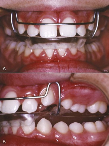
FIGURE 10-5 The bionator design, which removes much of the bulk of the activator, can include posterior facets or acrylic occlusal stops to control the amount or direction of tooth eruption. Note that for this patient who is biting into the bionator so that the mandible is advanced, the lower incisors are capped with acrylic to prevent them from erupting and control their tendency to tip facially. Usually the lower posterior teeth are free to erupt while eruption of the upper posterior teeth is impeded by an acrylic shelf across them. For this patient, the upper teeth are being allowed to erupt while eruption of the lower teeth is impeded.
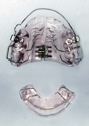
FIGURE 10-6 The twin-block appliance consists of individual maxillary and mandibular plates with ramps that guide the mandible forward when the patient closes down. The maxillary plate incorporates tubes for attachment of a headgear and often includes an expansion screw.

FIGURE 10-7 A to D, The Herbst appliance is the only fixed functional appliance. It uses a pin and tube apparatus to hold the mandible in an advanced position and is quite compatible with the presence of a fixed appliance on anterior teeth (but also can be used with bonded or removable splints). Note that for this patient the pin and tube attaches to steel crowns on the molars, which are sturdier than molar bands, and extensions from the lower crowns are bonded to the lower premolars. E, The MARA appliance is a Herbst variant that can be used with a complete fixed appliance but also holds the mandible in a forward position full-time. It is less bulky and more comfortable for the patient but may have more of a Class II elastics effect.
2 Active Tooth-Borne
These are largely modifications of activator and bionator designs that include expansion screws or springs to move teeth. This produces tooth movement that often replaces jaw growth modification with camouflage tooth movement. For this reason, active tooth-borne appliances have little or no place in modern orthodontics and now are used much less than previously.
3 Tissue-Borne
The Frankel appliance (which Frankel called the function regulator) is the only tissue-borne functional appliance (Figure 10-8). Insofar as possible, contact of the appliance with the teeth is avoided. Much of the appliance is located in the vestibule, holding the lips and cheeks away from the dentition. This makes it an arch expansion appliance in addition to its effects on jaw growth because the arches tend to expand when lip and cheek pressure is removed.

FIGURE 10-8 The Frankel appliance, shown here sitting on the lower cast, is the only functional appliance that is primarily tissue-borne rather than tooth-borne. The large buccal shields and lip pads reduce cheek and lip pressure on the dentition and provide the expansion of the maxillary arch that usually is needed as part of Class II correction; the lingual pad dictates the mandibular position. The appliance looks bulky, but for the most part, it is restricted to the buccal vestibule, and therefore it interferes less with speech and is more compatible with 24-hour wear than most other functional designs.
4 Hybrid
Hybrid functionals are composed of components that are common to functional appliances but are combined to meet a specific need, often in the treatment of jaw asymmetry (Figure 10-9). The components of functional appliances are shown in Table 10-1. They can be combined as needed for individual patients.
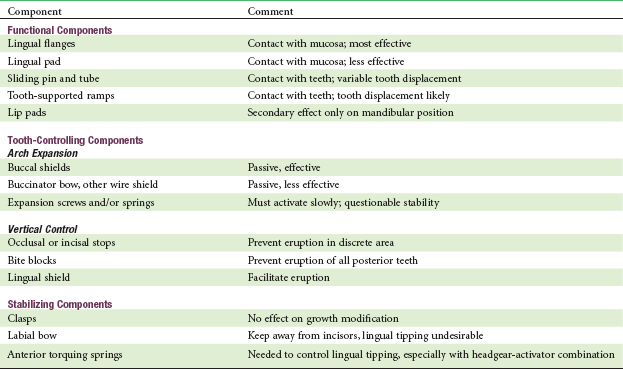
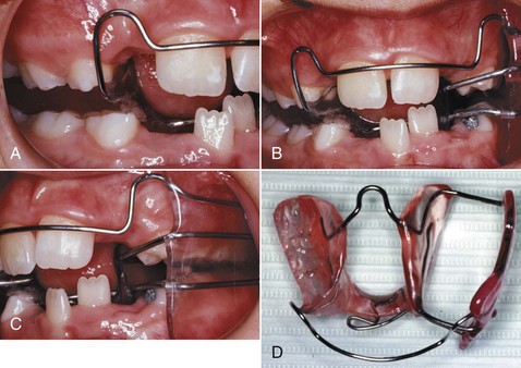
FIGURE 10-9 A hybrid functional appliance consists of the components of one type of functional on one side and components of another type on the other. For a child with a facial asymmetry, an appliance of the type shown here can be effective in improving both the vertical and a-p aspects of the problem. Note that the teeth are free to erupt on the left side (which requires a lingual as well as a buccal shield), while a bite block impedes eruption on the other. The bite is taken to bring the jaw to the midline, advancing the deficient side (here, the left) more than the other. (From Proffit WR, White RP, Sarver DM. Contemporary Treatment of Dentofacial Deformity. St. Louis: Mosby; 2003.)
Functional appliances are used primarily in late preadolescent children and during the adolescent growth spurt. They are discussed in more detail in Chapter 13.
Removable Appliances for Tooth Movement in Children
Tooth movement with removable appliances in children almost always falls into one of two major categories: (1) arch expansion, in which groups of teeth are moved to expand the arch perimeter, and (2) repositioning of individual teeth within the arch.
Active Plates for Arch Expansion
The framework of an active plate is a baseplate that serves as a base in which screws or springs are embedded and to which clasps are attached. The active element usually is a jackscrew placed so that it holds the parts of the plate together (see Figure 10-3). Opening the screw with a key then separates the sections of the plate. The screw offers the advantage that the amount of movement can be controlled, and the baseplate remains rigid despite being cut into two parts. The disadvantage is that the force system is very different from the ideal one for moving teeth. Rather than providing a light but continuous force, activation of the screw produces a heavy force that decays rapidly. Activating the screw too rapidly results in the appliance being progressively displaced away from the teeth rather than the arch being expanded as desired.
Removable Appliances with Springs for Tooth Movement
In contrast to the heavy, rapidly decaying forces produced by a screw, nearly optimum light continuous forces can be produced by springs in a removable appliance. Like the edges of an active plate, however, these springs contact the tooth surface at only one point, and it is difficult to use them for anything but tipping tooth movements (although this is theoretically possible) (Figure 10-10). The guideline for tooth movement with a spring from a removable appliance therefore is that this approach should be used only when a few millimeters of tipping movement is acceptable.
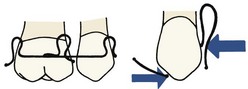
FIGURE 10-10 Diagrammatic representation of the spring assembly necessary for bodily retraction of a canine with a removable appliance. The spring on the mesial of the canine exerts a heavier force than the distal spring, leaving a net force to move the canine distally, while the couple necessary for control of root position is created by the opposing action of the two springs. Although bodily movement with a removable appliance is theoretically possible with spring arrangements of this type, the spring adjustments and clasp arrangements become too complex for practical clinical use. A fixed appliance is necessary for efficient bodily tooth movement.
Because these appliances are used primarily for minor tooth movement in children, they are discussed in more detail in Chapters 11 and 12.
Clear Aligner Therapy
The use of clear aligners in orthodontic treatment for adults became possible as vacuum-formed clear thermoplastic sheets were introduced into orthodontics in the 1980s. These “suck-down” materials were used initially as retainers and still are important for this purpose (see Chapter 17). It became apparent rather quickly, however, that if teeth were reset slightly and the vacuum-formed sheet was made to fit the reset teeth, a tooth moving device rather than a retainer would be the result. The device now could be, and quickly was, called an “aligner” because the typical use was to bring mildly displaced teeth back into alignment, as, for instance, when mild irregularity of maxillary or mandibular incisors occurred in an orthodontic patient after retainers were discontinued.
Only small amounts of tooth movement are possible with a single aligner, however, because of the stiffness of the plastic material. To obtain more than minor changes, it was necessary either to reshape the aligner or make a new one on a new cast with the teeth reset to a greater degree. Because the suck-down material is softened and becomes moldable when heated, it would be possible to alter the shape of an aligner with a heated instrument,2 and in an attempt to extend the use of aligners, a special heated pliers for this type of reshaping was offered as a way to avoid the cost and complexity of having to make multiple new aligners (Figure 10-11). This still allowed only minor tooth movement, and skill was required to obtain just the right amount of change in the aligner. A major limitation is that the plastic can only be stretched a maximum of about 3 mm (in 1 mm increments) before it becomes too thin to exert force. More recently, hard plastic bumps that snap into a hole in the aligner have been used to modify it for further tooth movement, which has the advantage that the plastic of the aligner is not stretched and thinned.3
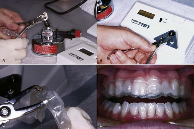
FIGURE 10-11 A pliers heated to the correct temperature (which must be checked) can be used to create a divot in an aligner to increase the amount of movement of a selected tooth without having to make a totally new aligner. A, Heating the special pliers. B, Checking the temperature. C, Creating a divot in the aligner, in this case to increase movement of one maxillary central incisor. D, The modified aligner in place, with increased pressure against the central incisor.
Despite these improvements, reshaped aligners are not a practical way to manage orthodontic problems that require movement of more than a few teeth. It became clear that a sequence of several aligners, made on a series of casts with some teeth reset in small increments (not more than 1 mm) to a new position, would be needed to correct even mild malalignment. Although a sequence of modified dental casts can be produced by hand and a short sequence of two to five aligners made from these casts works for minor tooth movement, this is prohibitively time consuming and difficult if more than a few aligners are required.
In the late 1990s, a new company, Align Technology, obtained venture capital to computerize the process of producing a sequence of casts with incremental changes on which aligners could be fabricated. The current approach (illustrated in more detail later) is to scan a patient’s teeth with an intraoral scanner that combines laser and optical scanning to create a digital model, make a series of incremental changes on the digital model, and produce a matching series of stereolithographic casts for aligner fabrication. With careful planning, this would result in a sequence of aligners that could correct more complex problems. From the beginning, it was recognized that since growth changes could not be predicted, the method would be useful only for treatment of adults or adolescents in whom growth modification was not needed, but these are the patients most interested in making an orthodontic appliance invisible or minimally visible.
This new approach was introduced with television publicity for “Invisalign” that was designed to create consumer interest in this new approach. The early days of Invisalign treatment were wrought with problems because staging of treatment, optimal rates of tooth movement, and indications for use of attachments on the teeth had not been worked out, and initial professional acceptance of the method was spotty. The technique has matured, however, as clinical evaluation has clarified the best sequence of steps in treatment and the amount of tooth movement in steps that should be attempted, and as the use of tooth-colored shapes bonded to the teeth has improved the appliance’s grip on the teeth and ability to move them. Although remarkably little has been published about the outcomes of Invisalign treatment, there is no doubt now that for many adults, complex malocclusions can be successfully treated in this way (see Chapter 18). As patents expire or are challenged successfully, it is likely that competitive companies will offer sequenced aligners based on modifications of the current techniques.
Invisalign Production Process
Steps in Preparing the Aligners: Diagnostic records for CAT are not different from those for any other type of orthodontic treatment, but for Invisalign sequenced aligners, an intraoral optical scan (which also records the initial set of the patient’s bite) or PVS (polyvinyl siloxane) impressions and a bite registration (maximum intercuspation) are obtained. The scan or impressions and photographs are submitted to the company along with the doctor’s initial instructions. The production process begins when the intraoral scan or impressions are used to create an accurate three-dimensional (3-D) digital model of each dental arch (Figure 10-12). These records are transferred electronically to a digital treatment facility (presently in Costa Rica).
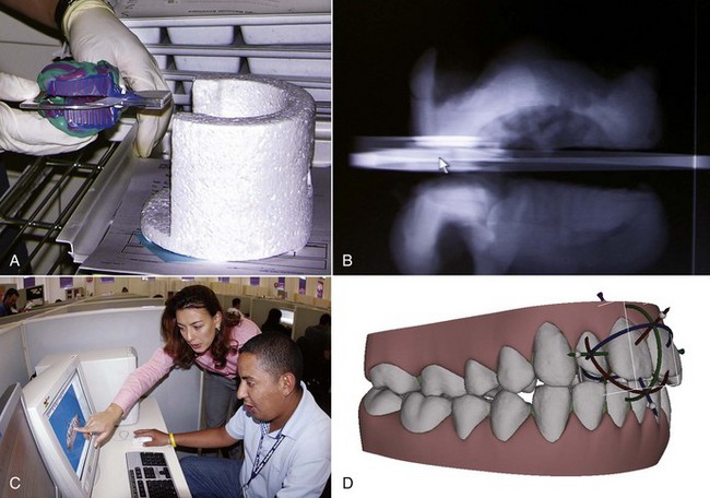
FIGURE 10-12 A, The first step in the production of a series of aligners using Invisalign’s computer technology is a CT scan of the impressions submitted by the doctor. The impressions are placed in a container before going into the CT scanner. B, This produces a three-dimensionally accurate digital image that is transmitted to a technology facility consisting entirely of computer work stations. C, In this view, the seated technician is conferring with one of the orthodontic advisors as the digital dental arches are displayed on the computer screen. D, Using the company’s proprietary software, virtual tooth movement in three dimensions can be created and staged as desired.
At the digital treatment facility, the teeth are digitally sectioned and cleaned up (obvious artifacts removed), the dental arches are related to each other, gingiva is added, movement is staged following the doctor’s instructions, and this preliminary plan is placed online for the doctor’s review as a “ClinCheck.” After the doctor is satisfied with the planned sequence of aligners, the set of digital models for a patient is transferred to a cast production facility, where a stereolithographic model for each step is fabricated (Figure 10-13). A clear plastic aligner is formed over each model, and the set of aligners is sent directly to the doctor.
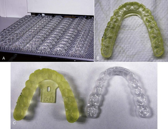
FIGURE 10-13 After the sequence of treatment steps has been adjusted if desired and approved by the doctor, who can access the digital models electronically after the preliminary treatment sequence has been put together, the models are used to fabricate a sequence of stereolithographic (SL) casts and a sequence of aligners are formed over the casts. A, SL casts emerging from the production machine. B, Close-up of a single SL cast. C, SL cast and the aligner formed from it.
Clinician’s Role in ClinCheck: With experience, doctors tend to be more specific in their initial prescription of what they want, but the sequence of steps and the amount of movement between steps is specified by algorithms built into the Treat software if this is not spelled out in detail in the prescription. In essence, when the ClinCheck is posted for the doctor to examine, the computer technician has sent a draft treatment plan for review (Figure 10-14). The software used by the computer technicians has default scenarios for different types of malocclusions and default rates of tooth movement. These defaults are satisfactory for simpler cases but not for the more complex ones.
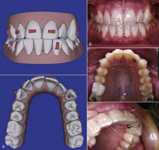
FIGURE 10-14 A, The Invisalign Clincheck form, as modified by the doctor, shows where bonded attachments are to be placed, the steps in the treatment sequence, and the amount of tooth movement at each step. For this patient, bonded attachments are to be placed as shown in the frontal and maxillary occlusal views. B, Bonded attachments on the facial surface of the teeth (same patient as the Clincheck form) are made of clear plastic in a variety of shapes. These are necessary to produce rotation or extrusion and facilitate other types of tooth movement. C and D, It is possible to bond a button on the lingual side of a tooth that is proving difficult to rotate and use a rubber band to rotate it along with the aligner.
For complex treatment, the doctor must customize the plan in terms of the amount and location of interproximal reduction of teeth (if any) that is to be done (Figure 10-15), the sequence of tooth movement steps, the rate of tooth movement with each subsequent aligner (often reducing the amount of movement at critical points), and the extent to which bonded shapes are to be used to increase the aligner’s grip on the teeth.
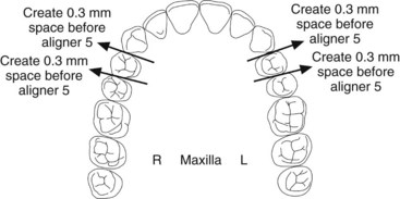
FIGURE 10-15 The Invisalign reproximation form (same patient as Figure 10-14), specifying how much enamel is to be removed from teeth and when in the sequence of aligners the reproximation will be done. For this patient, the upper incisors are to be reduced slightly in width to facilitate their alignment.
Considerations in Clinical Use of Clear Aligners: Although Invisalign is over a decade old, only a few studies of the outcomes of Invisalign treatment have been published in refereed professional journals.4 A recent prospective study used Invisalign’s software to evaluate the accuracy with which planned changes were accomplished, using the ratio of achieved to predicted change, and found that the highest accuracy (47%) was achieved during lingual constriction of the dental arches and the lowest (18%) for extrusion of maxillary incisors.4 Based on the existing studies and comments from experienced users, it seems clear now that Invisalign (and clear aligners more generally) do some things well and others not so well (Box 10-1). The limitations should be kept in mind when CAT is considered.
Several other considerations in the use of sequential aligners include the following:
• The use of attachments that are bonded to selected teeth greatly extends the possible tooth movement with aligners. In general, significant root movement (as in the closure of extraction sites) is almost impossible without the use of attachments, as is closure of open bites by elongation of incisor teeth; with attachments, both are possible (see Figures 18-40 and 18-41). Even with attachments, significant rotation of rounded teeth (canines and premolars) is difficult. It is possible to bond a button to a rotated tooth so that a rubber band can be used to rotate it while an aligner is being worn (see Figure 10-14). There is an increasing trend toward a combination approach to complex treatment, using a short phase of partial fixed appliances or auxiliaries in addition to the sequence of aligners.
• Interproximal enamel reduction (IPR) to obtain space for aligning crowded teeth often is part of the treatment plan. If IPR is planned, removal of interproximal enamel in the canine-premolar region to provide space can be used in addition to reduction in the width of incisors. The amount of interproximal reduction is part of the doctor’s prescription (see Figure 10-15).
• Patients must be monitored carefully to verify that tooth movement is tracking with the series of aligners (i.e., that all teeth are seated completely in the aligner after it has been worn for the specified period of time). If the teeth are not tracking, there are several possibilities: not enough wear of the aligners by the patient, insufficient interproximal reduction, insufficient crown height or shape to allow a grip on the tooth or teeth to be moved, wrong type or position of bonded attachments, or movement created in ClinCheck that is too fast to be possible biologically. A refinement or midcourse correction, with a new intraoral scan or PVS impressions and revision of the treatment plan, often is necessary in treatment of complex problems.
• Aligners cover the teeth like a bleaching tray, and they can be used to bleach during treatment (unless the patient has bonded attachments on the anterior teeth). If this is done, it is important to remember that tooth movement causes transient pulpitis and so does bleaching. The combination of the two procedures can lead to significant tooth sensitivity. This can be controlled by increasing the intervals between bleaching sessions, but bleaching usually is better deferred until the retention stage.
The clinical use of clear aligners in adjunctive and comprehensive treatment is discussed in greater detail in Chapter 18.
Fixed Appliances
Contemporary fixed appliances are predominantly variations of the edgewise appliance system. The only current fixed appliance system that does not use rectangular archwires in a rectangular slot is the Begg appliance, and practitioners using it have shown renewed interest in rectangular archwires at the finishing stage as the original Begg appliance has morphed into the Tip-Edge appliance. The focus in this and the succeeding chapters therefore is almost entirely on the contemporary edgewise appliance, with occasional reference to the modified Begg technique.
The Development of Contemporary Fixed Appliances
Angle’s Progression to the Edgewise Appliance
Edward Angle’s position as the “father of modern orthodontics” is based not only on his contributions to classification and diagnosis but also on his creativity in developing new orthodontic appliances. With few exceptions, the fixed appliances used in contemporary orthodontics are based on Angle’s designs from the early twentieth century. Angle developed four major appliance systems:
E-Arch: In the late 1800s, a typical orthodontic appliance depended on some sort of rigid framework to which the teeth were tied so that they could be expanded to the arch form dictated by the appliance. Angle’s first appliance, the E-arch, was an improvement on this basic design (Figure 10-16). Bands were placed only on molar teeth, and a heavy labial archwire extended around the arch. The end of the wire was threaded, and a small nut placed on the threaded portion of the arch allowed the archwire to be advanced so that the arch perimeter increased. Individual teeth were simply ligated to this expansion arch. This appliance still could be found in the catalogs of some mail-order orthodontic laboratories as late as the 1980s, perhaps because of its simplicity, and despite the fact that it can deliver only heavy interrupted force.
Pin and Tube: The E-arch was capable only of tipping teeth to a new position. It was not able to precisely position any individual tooth. To overcome this difficulty, Angle began placing bands on other teeth and used a vertical tube on each tooth into which a soldered pin from a smaller archwire was placed. With this appliance, tooth movement was accomplished by repositioning the individual pins at each appointment.
An incredible degree of craftsmanship was involved in constructing and adjusting this pin and tube appliance, and although it was theoretically capable of great precision in tooth movement, it proved impractical in clinical use. It is said that only Angle himself and one of his students ever mastered the appliance. The relatively heavy base arch meant that spring qualities were poor, and the problem therefore was compounded because many small adjustments were needed.
Ribbon Arch: Angle’s next appliance modified the tube on each tooth to provide a vertically positioned rectangular slot behind the tube. A ribbon archwire of 10 × 20 gold wire was placed into the vertical slot and held with pins (Figure 10-17). The ribbon arch was an immediate success, primarily because the archwire, unlike any of its predecessors, was small enough to have good spring qualities and therefore was quite efficient in aligning malposed teeth. Although the ribbon arch could be twisted as it was inserted into its slot, the major weakness of the appliance was that it provided relatively poor control of root position. The resiliency of the ribbon archwire simply did not allow generation of the moments necessary to torque roots to a new position.
Edgewise: To overcome the deficiencies of the ribbon arch, Angle reoriented the slot from vertical to horizontal and inserted a rectangular wire rotated 90 degrees to the orientation it had with the ribbon arch, thus the name “edgewise” (Figure 10-18). The dimensions of the slot were altered to 22 × 28 mils, and a 22 × 28 precious metal wire was used. These dimensions, arrived at after extensive experimentation, did allow excellent control of crown and root position in all three planes of space.
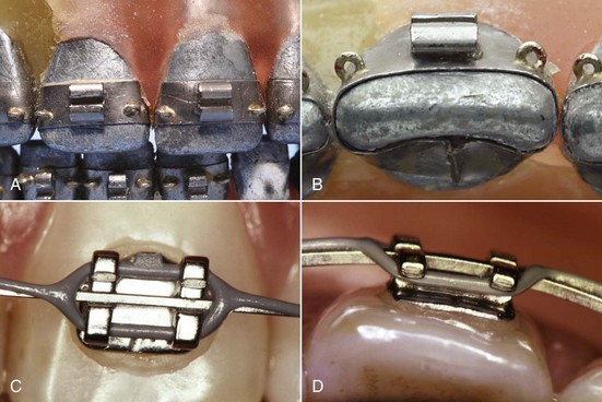
FIGURE 10-18 A and B, Angle’s edgewise appliance received its name because the archwire was inserted at a 90-degree angle to the plane of insertion of the ribbon arch, which made it wider than it was tall. The rectangular wire could be twisted to create torque (see Figure 10-22). It was tied into a rectangular slot with wire ligatures, making excellent control of root position possible. The original appliance is seen here on a typodont. Note the narrow brackets (double width on the maxillary centrals, which are wider teeth), which were soldered to gold bands. Also note the eyelets soldered on the corners of the bands. These were used for ligature ties to the archwire as needed for rotational control. C and D, Close-up views of a modern edgewise twin bracket with a rectangular archwire in place. The wire is held in the bracket by an elastomeric ligature, here part of a chain of ligatures that also keep spaces closed between the teeth.
After its introduction in 1928, this appliance became the mainstay of multibanded fixed appliance therapy, although the ribbon arch continued in common use for another decade.
Other Early Fixed Appliance Systems
Labiolingual, Twin Wire: Before Angle, placing attachments on individual teeth simply had not been done, and Angle’s concern about precisely positioning each tooth was not widely shared during his lifetime. In addition to a variety of removable appliances utilizing fingersprings for repositioning teeth, the major competing appliance systems of the first half of the twentieth century were the labiolingual appliance, which used bands on first molars and a combination of heavy lingual and labial archwires to which fingersprings were soldered to move individual teeth, and the twin-wire appliance. This appliance used bands on incisors as well as molars and featured twin 10 mil steel archwires for alignment of the incisor teeth. These delicate wires were protected by long tubes that extended forward from the molars to the vicinity of the canines. None of these appliances, however, were capable of more than tipping movements except with special and unusual modifications. They have disappeared from contemporary use.
Begg Appliance: Given Angle’s insistence on expansion of the arches rather than extraction to deal with crowding problems, it is ironic that the edgewise appliance finally provided the control of root position necessary for successful extraction treatment. The appliance was being used for this purpose within a few years of its introduction. Charles Tweed, one of Angle’s last students, was the leader in the United States in adapting the edgewise appliance for extraction treatment. In fact, little adaptation of the appliance was needed. Tweed moved the teeth bodily and used the subdivision approach for anchorage control, first sliding the canines distally along the archwire, then retracting the incisors (see Figure 9-33).
Raymond Begg had been taught the ribbon arch appliance at the Angle school before his return to Australia in the 1920s. Working independently in Adelaide, Begg also concluded that extraction of teeth was often necessary, and set out to adapt the ribbon arch appliance so that it could be used for better control of root position.
Begg’s adaptation took three forms: (1) he replaced the precious metal ribbon arch with high-strength 16 mil round stainless steel wire as this became available from an Australian company in the late 1930s; (2) he retained the original ribbon arch bracket, but turned it upside down so that the bracket slot pointed gingivally rather than occlusally; and (3) he added auxiliary springs to the appliance for control of root position. In the resulting Begg appliance (Figure 10-19),5 friction was minimized because the area of contact between the narrow ribbon arch bracket and the archwire was very small and the force of the wire against the bracket was also small. Binding was minimized because Begg’s strategy for anchorage control was tipping/uprighting (see Figure 8-21), and tipping minimizes the angle of contact between the wire and corner of the bracket.
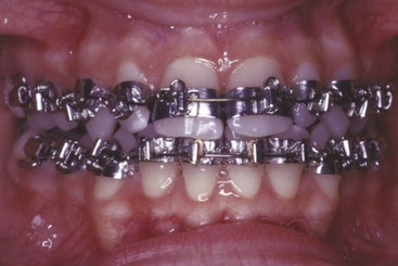
FIGURE 10-19 The Begg appliance uses a modification of the ribbon arch attachment, into which round archwires are pinned. A variety of auxiliary archwires are used in this system to obtain control of root position. For this patient late in treatment, the mandibular archwire is held in place in the central incisors with brass pins, and auxiliary springs (placed in the vertical slot and also serving as pins to retain the archwire) are being used to position the roots of several teeth (they are seen clearly in the maxillary central incisors, activated to move the roots distally).
Although the progress records with his approach looked vastly different, it is not surprising that Begg’s overall result in anchorage control was similar to Tweed’s, since both used two steps to compensate for resistance to sliding. The Begg appliance is still seen in contemporary use though it has declined in popularity and often appears now in a hybrid form, with brackets that allow the use of rectangular wires in finishing (Figure 10-20).6 It is a complete appliance in the sense that it allows good control of crown and root position in all three planes of space.
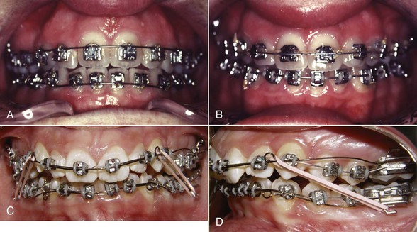
FIGURE 10-20 Modified brackets, such as this stage-4 bracket with both an edgewise slot (either 18 × 25 or 21 × 25) and a 22 × 32 gingival slot in which a wire can be pin-retained, allow a combination of Begg and edgewise mechanics. A, For this patient in the first stage of treatment, NiTi wires are pinned in place (which allows free movement in the slot as compared to holding them in the edgewise slot with a ligature). B, Later in treatment, heavier wires are tied into the edgewise slot. C, Tip-Edge bracket, which has a rectangular slot cut away on one side to allow crown tipping in that direction with no incisal deflection of the archwire. This allows the teeth to be tipped in the initial stage of treatment, but a rectangular wire can be used for torque in finishing. D, Tip-Edge brackets in the initial stage of treatment, with small diameter steel archwires. (A and B, Courtesy Dr. W. J. Thompson; C and D, courtesy Dr. D. Grauer.)
Contemporary Edgewise
The Begg appliance became widely popular in the 1960s because it was more efficient than the edgewise appliance of that era, in the sense that equivalent results could be produced with less investment of the clinician’s time. Developments since then have reversed the balance: the contemporary edgewise appliance has evolved far beyond the original design while retaining the basic principle of a rectangular wire in a rectangular slot, and now is more efficient than the Begg appliance, which is the reason for its almost universal use now. Major steps in the evolution of the edgewise appliance include:
Automatic Rotational Control: In the original appliance, Angle soldered eyelets to the corners of the bands, so a separate ligature tie could be used as needed to correct rotations or control the tendency for a tooth to rotate as it was moved (see Figure 10-18). Now rotation control is achieved without the necessity for an additional ligature by using either twin brackets or single brackets with extension wings that contact the underside of the archwire (Lewis or Lang brackets) (Figure 10-21) to make it easier to obtain the necessary moment in the rotational plane of space.
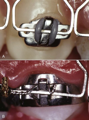
FIGURE 10-21 In contemporary edgewise appliances, the alternative methods for rotation control are twin brackets (as seen in Figure 10-20, C and D) or single brackets with antirotation wings. A, Bonded single-wing (Lang) bracket with antirotation arms. B, Single-wing (Lewis) bracket welded to a premolar band. In both A and B, note that the end of an antirotation arm would contact the back of the archwire if the tooth began to rotate, creating the needed anti-rotation couple. Note also that the slightly undersized rectangular wire crosses the bracket at an angle, creating a moment to control the position of the roots.
Alteration in Bracket Slot Dimensions: The significance of reducing Angle’s original slot size from 22 to 18 mils and the implications of using the larger slot with undersize steel wires have been discussed in Chapter 9. In essence, there are now two modern edgewise appliances, because the 18 and 22 slot appliances are used rather differently. Chapters 14 to 16 focus on these differences.
Straight-Wire Prescriptions: Angle used the same bracket on all teeth, as did the other appliance systems. In the 1980s, Andrews developed bracket modifications for specific teeth to eliminate the many repetitive bends in archwires that were necessary to compensate for differences in tooth anatomy, and bonding made it much easier to have different brackets for each tooth. The result was the “straight-wire” appliance.7 This was the key step in improving the efficiency of the edgewise appliance.
In the original edgewise appliance, faciolingual bends in the archwires (first-order, or in-out, bends) were necessary to compensate for variations in the contour of labial surfaces of individual teeth. In the contemporary appliance, this compensation is built into the base of the bracket itself. This reduces the need for compensating bends but does not eliminate them because of individual variations in tooth thickness.
Angulation of brackets relative to the long axis of the tooth is necessary to achieve proper positioning of the roots of most teeth. Originally, this mesiodistal root positioning required angled bends in the archwire, called second-order, or tip, bends. Angulating the bracket or bracket slot decreases or removes the necessity for these bends.
Because the facial surface of individual teeth varies markedly in inclination to the true vertical, in the original edgewise appliance it was necessary to place a varying twist (referred to as third-order, or torque, bends) in segments of each rectangular archwire, in order to make the wire fit passively. Torque bends were required for every patient in every rectangular archwire, not just when roots needed to be moved facially or lingually, in order to avoid inadvertent movements of properly positioned teeth. The bracket slots in the contemporary edgewise appliance are inclined to compensate for the inclination of the facial surface, so that third-order bends are less necessary.
The angulation and torque values built into the bracket are often referred to as the appliance prescription. Obviously, any prescription based on a group average would precisely position only the average tooth and would not be correct for outliers in a normal population.
The edgewise appliance continues to evolve. Current commercially available edgewise appliances and their bracket prescriptions are reviewed in some detail at the end of this chapter. Before getting to them, let us examine banding versus bonding as the means of fixing the appliance in place.
Bands for Attachments
Until the 1980s, the only practical way to place a fixed attachment was to put it on a band that could be cemented to a tooth. The pioneer orthodontists of the early 1900s used clamp bands, which were tightened around molar teeth by screw attachments. Only with the advent of custom-fitted gold bands that were fabricated with special pliers, was it practical to place fixed attachments on more than a few teeth. Preformed steel bands came into widespread use during the 1960s but are used now primarily for molar teeth.
There are many advantages to bonding brackets, so it is no longer appropriate to routinely place bands on all teeth. However, a number of indications still exist for use of a band rather than a bonded attachment, including:
1. Teeth that will receive heavy intermittent forces against the attachments. This is the primary indication for banding now. An excellent example is an upper first molar against which extraoral force will be placed via a headgear. The twisting and shearing forces often encountered when the facebow is placed or removed are better resisted by a steel band than by a bonded attachment.
2. Teeth that will need both labial and lingual attachments such as a molar with both headgear and lingual arch tubes. Isolated bonded lingual attachments that are not tied to some other part of the appliance can be swallowed or aspirated if something comes loose.
3. Teeth with short clinical crowns, so that bonded brackets are difficult to place correctly. If attached to a band, a tube or bracket can slightly displace the gingiva as it is carried into proper position. It is much more difficult to do this with bonded attachments. The decision to band rather than bond second premolars in adolescents is often based on the length of the clinical crown.
4. Teeth with extensive restorations. Although bonding to porcelain, gold, or amalgam is possible, bond strength tends to be low, and debonding from porcelain often will damage its appearance by removing the glaze. For that reason, if little intact enamel is available for bonding, banding may be easier and more efficient.
Although there are exceptions, the rule in contemporary orthodontics is that bonded attachments are almost always preferred for anterior teeth and premolars; bands usually are preferred for first molars, especially if both buccal and lingual attachments are needed; and second molars are bonded if exposure of the crown allows it, banded if not. There is an increasing trend toward bonded attachments on all teeth, however, especially in older patients who have longer clinical crowns and tighter contacts.
Steps in Banding
Separation: Tight interproximal contacts make it impossible to properly seat a band, which means that some device to separate the teeth usually must be used before banding. Although separators are available in many varieties, the principle is the same in each case: a device to force or wedge the teeth apart is left in place long enough for initial tooth movement to occur, so that the teeth are slightly separated by the appointment at which bands are to be fitted.
Two main methods of separation are used for posterior teeth: (1) separating springs (Figure 10-22), which exert a scissors action above and below the contact, typically opening enough space for banding in approximately 1 week; and (2) elastomeric separators (“doughnuts”), applied as shown in Figure 10-23, which surround the contact point and squeeze the teeth apart over a period of several days.
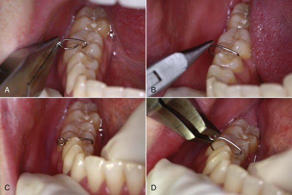
FIGURE 10-22 Separation with steel separating springs. A, The spring is grasped at the base. B, The bent-over end of the longer leg is placed in the lingual embrasure, and the spring is pulled open so the shorter leg can slip beneath the contact. C, The spring in place, with the helix to the buccal. D, The spring can be removed most easily by squeezing the helix, forcing the legs apart.
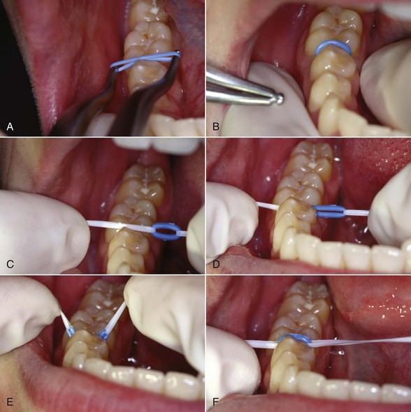
FIGURE 10-23 Separation with an elastomeric ring or “doughnut.” A, The elastomeric ring is placed over the beaks of a special pliers and stretched, then B, one side is snapped through the contact and the pliers slipped out so that the doughnut now surrounds the contact; C, an alternative to the special pliers is two loops of dental floss, placed so they can be used to stretch the ring. D, The dental floss is snapped through the contact and the doughnut is pulled underneath the contact; E, the doughnut is pulled upward, and F, the doughnut is snapped into position. At that point, the dental floss is removed.
From the patient’s perspective, steel spring separators are easier to tolerate, both when they are being placed and removed, and as they separate the teeth. These separators tend to come loose and may fall out as they accomplish their purpose, which is their main disadvantage and the reason for leaving them in place only a few days, not for more than a week. Elastomeric separators are more difficult to insert but are usually retained well when they are around the contact and so may be left in position for somewhat longer periods. Because elastomeric separators are radiolucent, a serious problem can arise if one is lost into the interproximal space. It is wise to use a brightly colored elastomeric material to make a displaced separator more visible, and these separators should not be left in place for more than 2 weeks.
Fitting Bands: With the wide availability of preformed bands now, forming bands clinically is too inefficient. Almost all bands are supplied now with prewelded attachments. This saves clinical time and allows the use of templates to assure accurate placement of the attachment.
Fitting a preformed band involves stretching the stainless steel material over the tooth surface. This simultaneously contours and work-hardens the initially rather soft band material. It follows that heavy force is needed to seat a preformed band. This force should be supplied by the masticatory muscles of the patient, not by the arm strength of the dentist or dental assistant. Patients can bite harder and with much greater control, a fact best appreciated on the rare occasions when a patient is unable to bite bands to place and the orthodontist has to do it with hand pressure.
Preformed bands are designed to be fitted in a certain sequence, and it is important to follow the manufacturer’s instructions. A typical maxillary molar band is designed to be placed initially by hand pressure on the mesial and distal surfaces, bringing the band down close to the height of the marginal ridges. Then it is driven to place by pressure on the mesiobuccal and distolingual surfaces. The final seating is with heavy biting force on the distolingual corner. Lower molar bands are designed to be seated initially with hand pressure on the proximal surfaces and then with heavy biting force along the buccal but not the lingual margins. Maxillary premolar bands are usually seated with alternate pressure on the buccal and lingual surfaces, while mandibular premolar bands, like mandibular molars, are designed for heavy pressure on the buccal surface only.
Cementation: New cements specifically designed for orthodontic use have supplanted the zinc phosphate and early glass ionomer cements used in the twentieth century. These tend to be a composite of glass ionomer and resin materials and usually are light-cured. Their use has greatly reduced problems with leakage beneath bands that previously was a risk for decalcification of banded teeth.
All interior surfaces of an orthodontic band must be coated with cement before it is placed, so that there is no bare metal. As the band is carried to place, the occlusal surface should be covered so that cement is expressed from the gingival as well as the occlusal margins of the band (Figure 10-24).
Bonded Attachments
Bonding of attachments, eliminating the need for bands, was a dream for many years before rather abruptly becoming a routine clinical procedure in the 1980s. Bonding is based on the mechanical locking of an adhesive to irregularities in the enamel surface of the tooth and to mechanical locks formed in the base of the orthodontic attachment. Successful bonding in orthodontics therefore requires careful attention to three components of the system: the tooth surface and its preparation, the design of the attachment base, and the bonding material itself.
Preparation of the Tooth Surface: Before bonding an orthodontic attachment, it is necessary to remove the enamel pellicle and to create irregularities in the enamel surface. This is accomplished by gently cleaning and drying the enamel surface (avoiding heavy pumicing), then treating it with an etching agent, usually 37% unbuffered phosphoric acid for 20 to 30 seconds. The effect is to remove a small amount of the softer interprismatic enamel and open up pores between the enamel prisms, so the adhesive can penetrate into the enamel surface (Figure 10-25). At present, etching and priming the tooth surface often are done in a single step, especially when rebonding after a bracket is loose or lost. The tooth surface must not be contaminated with saliva, which promotes immediate remineralization, but the new tooth preparation materials now minimize the need to have a perfectly dry tooth surface.
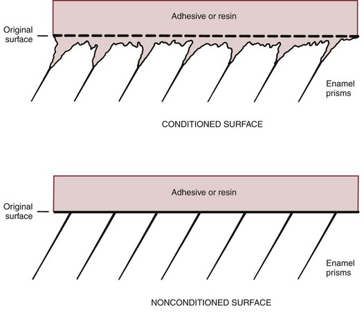
FIGURE 10-25 Diagrammatic representation of the effect of preparation of the enamel surface before bonding. Pretreatment with phosphoric acid creates minute irregularities in the enamel surface, allowing the bonding material to form penetrating “tags” that mechanically interlock with the enamel surface.
Surface of Attachments: The base of a metal bonded bracket or tube must be manufactured so that a mechanical interlock between the bonding material and the attachment surface can be achieved. Either chemical bonding or mechanical interlocking can be used with ceramic brackets. The strength of chemical bonds can become high enough to create problems in debonding, so mechanical retention now is preferred for ceramic as well as metal brackets.
Bonding Materials: A successful bonding material must meet a set of formidable criteria: it must be dimensionally stable; it must be quite fluid, so that it penetrates the enamel surface; it must have excellent inherent strength; and it must be easy to use clinically.
Until recently, light-activated filled acrylic (bis-GMA) resins were the preferred bonding materials, but new self-adhesive resin cements (which incorporate a self-etch primer or a self-adhesive component) are beginning to replace them because they require less preparation of the tooth surface. The new cements do not have as much bond strength with metal brackets as a widely used etch-and-rinse bonding material, but one of them already has the same strength with ceramic brackets.8
Modified glass-ionomer cements also can be used as orthodontic bonding agents. Their possible advantage is less decalcification around the brackets because of fluoride release (see further discussion below); their great disadvantage is significantly less strength and therefore a greater chance of loose brackets that require rebonding during treatment.
Direct Bonding: During direct bonding, bracket position is determined intraorally by the clinician during the bonding procedure. This technique can be used quite successfully as a routine clinical procedure. Even when most attachments are bonded indirectly (as described below), direct bonding is much more efficient whenever a single bracket must be repositioned. After preparation of the tooth surface, either a chemically activated composite resin with a very rapid setting time or a light-activated material can be used.
The major difficulty with direct bonding is that the dentist must be able to judge the proper position for the attachment and must carry it to place rapidly and accurately. There is less opportunity for precise measurements of bracket position or detailed adjustments than there would be at the laboratory bench. It is generally conceded that for this reason, direct bonding does not provide as accurate a placement of brackets as indirect bonding. On the other hand, direct bonding is easier, faster (especially if only a few teeth are to be bonded), and less expensive (because the laboratory fabrication steps are eliminated).
Steps in the direct bonding technique when using a light-activated resin for each bracket are illustrated in Figure 10-26. Light-cured resins now are used more frequently than chemically activated resins because the newer light-cured materials have more flexibility in working time and usually have higher bond strengths.
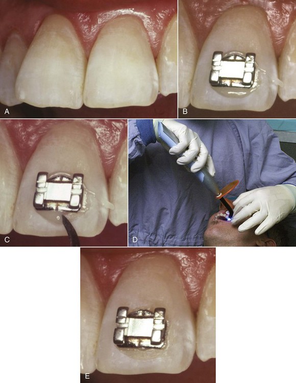
FIGURE 10-26 Steps in direct bonding. A, After etching, the tooth surface has a somewhat chalky or frosted appearance if dried (drying is no longer necessary with modern tooth preparation materials, but the tooth surface must be etched). B, A small amount of the bonding agent is squeezed into the mesh on the back of the bracket, and it is pressed to place on the tooth surface. C, Excess bonding material is removed from around the bracket. D, For light-cured materials, a cordless light now is the most convenient way to activate the adhesive bonding process. E, The bracket bonded in place.
Indirect Bonding: Indirect bonding is done by accurately placing the brackets on dental casts in a laboratory, then using a template or tray to transfer the bracket positions to the patient. The advantage is more precise location of brackets than is possible with direct bonding because the teeth can be examined from all angles without the limitations of cheeks and saliva. Indirect setups can be done by the clinician in the office laboratory, but more frequently they now are done on stereolithographic casts made from impressions sent to a company (Cadent, E-Models, others) that also produces digital casts as part of diagnostic records. An alginate impression, poured relatively rapidly in the office lab, gives an accurate enough working cast for indirect bonding, but more stable impressions are needed for later digital scanning. Laboratory and clinical steps in indirect bonding are illustrated in Figure 10-27.
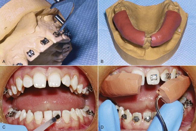
FIGURE 10-27 Steps in indirect bonding. A, Brackets are placed precisely as desired on a cast of the teeth and held in place with a filled resin. B, After the brackets are cured in the ideal position, a transfer tray is formed from a vinyl polysiloxane putty. The trays are removed from the working cast after soaking in warm water and trimmed. C, The teeth are isolated, etched, and a chemically cured two-paste resin is painted on the etched enamel and the brackets. Then, the transfer trays are inserted. D, After the resin has completely set, the trays are carefully removed, leaving the brackets bonded to the teeth.
Obtaining optimal bond strength while minimizing flash around the bracket can be a challenge during indirect bonding, since the presence of a tray prevents removing uncured flash. One solution is to use “no-mix” chemically activated materials. The composite resin is placed on the tooth surface in unpolymerized form, while the polymerization catalyst is placed on the back of the brackets. When the tray carrying the brackets is placed against the tooth surface, the resin immediately beneath the bracket is activated and polymerizes, but excess resin around the margins of the brackets does not polymerize and can easily be scaled away when the bracket tray is removed. Some studies, however, have found increased bond failures with this technique because it relies on diffusion for proper polymerization. An alternative is to use a chemical cure resin that is mixed prior to application to the brackets and teeth, but care must be taken to minimize excess resin. Finally, a flowable light-cured material can be used with a transparent tray, but polymerizing the resin at each bracket through or around the tray takes more time than using a chemical cure. With any of these techniques, proper isolation is critical for obtaining adequate bond strength.
At present, routine use of indirect bonding is gaining popularity. Custom brackets that were manufactured for an individual patient require precise placement that can be achieved only by indirect bonding. More generally, the poorer the visibility, the more difficult direct bonding becomes and the greater the indication for an indirect approach. For this reason, indirect bonding is almost a necessity for lingual attachments. Bonding an isolated lingual hook or button is not difficult, but precisely positioning the attachments for a lingual appliance is, and even the placement of a fixed lingual retainer is done more easily with indirect technique and a transfer tray.
Debanding/Debonding: It is as important to remove a fixed appliance safely as to place it properly. Bands are largely retained by the elasticity of the band material as it fits around the tooth. This is augmented by the cement that seals between the band and the tooth, but a band retained only by cement was not fitted tightly enough. No orthodontic band cement bonds strongly to enamel (which is why band cements cannot be used to bond brackets). When the band is distorted by force to remove it, the cement breaks away from the band or the tooth, and there is almost no chance of damaging the enamel surface.
The greater strength of bonding adhesives becomes a potential problem in debonding. When a bonded bracket is removed, failure at one of three interfaces must occur: between the bonding material and the bracket, within the bonding material itself, or between the bonding material and the enamel surface. If a strong bond to the enamel has been achieved, which is the case with the modern materials, failure at the enamel surface on debonding is undesirable because the bonding material may tear the enamel surface as it pulls away from it. The interface between the bonding material and the bracket is the usual and preferred site of failure when brackets are removed. The safest way to remove metal brackets is to distort the bracket base, which induces failure between it and the bonding adhesive. This damages the bracket so that it cannot be reused. The major reason for not recycling and reusing brackets is the possibility of enamel damage when they are removed without distorting the base. If brackets can be removed without damage they can be cleaned, sterilized, and reused without risk to the patient in exactly the same way as other medical devices.
Ceramic brackets are a particular problem for debonding because their base cannot be distorted. They break before they bend. There are two ways to create adhesion between a ceramic bracket and the bonding adhesive: mechanical retention through undercuts on the bracket base, as is done with metal brackets, or chemical bonding between the adhesive and a treated bracket base. It is quite possible to create such a strong bond between the adhesive and a chemically treated bracket base that failure will not occur there, but then when the bracket is removed, there is a real chance of enamel surface damage. Reports of enamel damage on debonding began to appear soon after ceramic brackets were introduced and have been a problem ever since.
Modifications to ceramic brackets to enhance the chance of debonding at the right interface and electrothermal and laser techniques to weaken the adhesive during debonding are discussed in the section below on modern bracket materials.
Prevention and Control of Enamel Decalcification
Prevalence and Prevention: White spots, unsightly areas of decalcification around brackets, are a well-known problem that has become worse since bonded brackets have largely replaced bands and more of the tooth surface is exposed. Although bonded brackets do not directly damage the teeth, they make plaque removal more difficult. Maxillary incisors, particularly lateral incisors, are the greatest problem area. A recent study of 338 patients treated in a university orthodontic clinic reported that 36% had at least one lesion on a maxillary incisor tooth at the end of treatment despite preventive efforts. Risk factors were young age at the beginning of treatment, poor hygiene before the start of treatment, and citations for poor hygiene during treatment.9
The lesions can be carious or noncarious; carious lesions are rough and porous, noncarious are smooth and shiny. Some natural remineralization occurs, and the carious lesions have a better prognosis for this because the surface is porous. Nevertheless, the lesions are not likely to completely correct themselves. A recent 14-year follow-up showed that most of the white spot lesions noted at the end of treatment were still there.10
Fluoridated water and a fluoride-containing toothpaste are effective as caries-controlling measures in the general population and should be considered an essential part of a program to prevent white spot lesions. There is some evidence that a daily 0.05% neutral sodium fluoride rinse is effective in preventing white spots.11 The major problem with the toothpaste and rinse, of course, is sporadic or no compliance. For caries-prone patients in general, a fluoride varnish application at 6-month intervals is recommended; for noncompliant orthodontic patients who are developing lesions, more frequent fluoride varnish applications may be helpful, though the evidence to support this is weak.12 A short-term daily chlorhexidine rinse program (usually 14 days) could be a last resort approach to a noncompliant patient with persistent plaque accumulation, despite the staining of teeth that occurs.
A number of fluoride-releasing bonding agents have been offered commercially in the hope that they would control decalcification around brackets, but a 2010 review of the published data concluded that there is no good evidence that any are effective against white spots.12 The problem is that the fluoride release is large initially, then dwindles to little or nothing long before a typical 18 to 24 month orthodontic treatment is completed. A recent report shows that in the laboratory, a reasonably sustained fluoride release from elastomeric modules can be obtained that is high enough to be clinically effective over a period of 25 days.13 Since elastomeric ligature ties are replaced at every appointment, if significant release can be maintained for appointment intervals of 6 to 8 weeks, this approach might be more successful, but no clinical data have yet been presented.
Treatment for White Spots: In a recent review, Guzman-Armstrong et al outlined a multistep approach to treatment that is the basis for the following discussion14:
• After braces are removed, the first step in treatment of white spot lesions is to allow natural remineralization to occur over a period up to 6 months. Active lesions with a dull, pitted, and porous surface have a better prognosis for regaining normal enamel translucency than arrested lesions with a flat or shiny surface, but reduction in the size of active and arrested lesions usually occurs. During this time, fluoride in high concentrations should be avoided because it can arrest remineralization and lead to staining. Use of other materials to promote remineralization (Recaldent, MI Paste, MI Paste Plus) has been proposed, but no long-term clinical studies exist to demonstrate an additional benefit over natural remineralization.
• After natural remineralization has been given time to occur, a second step would be external bleaching to help camouflage white spots, which often is well-received by patients. This should be used only in patients with good hygiene and should be followed by topical fluoride because bleaching increases caries susceptibility.
• A third step for patients with severe problems that were unsatisfactory after bleaching is acid microabrasion to eliminate the external layer of the lesion, followed by application of Recaldent or MI Paste Plus. The microabrasion is done with repeated applications of a pumice-hydrochloric acid slurry, which physically removes discolored enamel and also creates a smooth enamel surface with different optical properties. Although the loss of enamel thickness rarely exceeds 250 µm, treated teeth may appear darker after treatment, and external bleaching at that point can be helpful in restoring normal color and lustre. A study of microabrasion effectiveness in 16 affected teeth in 8 patients reported a mean reduction of 83% in the size of white spot areas, with the greatest improvement in larger lesions.15
• The ultimate step is restorative treatment with resin or porcelain veneers.
The first step would appropriately be managed by the orthodontist. Beyond that point, involving the family dentist or a colleague in restorative dentistry would be wise.
Characteristics of Contemporary Fixed Appliances
Cast versus Metal-Injected-Molded Stainless Steel Brackets: The brackets and tubes for an edgewise appliance must be precisely manufactured so that the internal slot dimensions are accurate to at least 1 mil. Until the recent introduction of ceramic and titanium brackets, fixed appliances had been fabricated entirely from stainless steel for many years, and steel remains the standard material for appliance components.
There are two contemporary ways to produce steel edgewise brackets and tubes: by metal-injection molding (MIM) or by casting. Most of the brackets and tubes for contemporary appliances now are produced by MIM, but some are cast. The greatest precision of bracket slot size is achieved by milling the slot of a cast bracket, which corrects errors introduced by shrinkage of the casting as it cools.
Titanium as an Alternative to Stainless Steel: Nickel is a potentially allergenic material. Given the significant nickel content of stainless steel, it is fortunate for orthodontists that mucosal allergic reactions to nickel are much less prevalent than cutaneous reactions. Cutaneous sensitization to nickel often develops from skin contact with cheap jewelry, and 10% or more of the population now have some degree of sensitivity to nickel.16 Most patients who show skin reactions tolerate stainless steel orthodontic appliances quite satisfactorily, but a few do not, and there is concern that this number is increasing. Some European countries are now considering a ban on steel orthodontic appliances because of the risk of allergic responses.
The metal alternatives to steel are gold, long since abandoned because of performance and cost considerations, and titanium, which contains no nickel and is exceptionally biocompatible. Titanium archwires have been used since the 1980s, and the use of bonded titanium brackets and tubes has increased rapidly since the turn of the century. In addition to its hypoallergenic properties, titanium brackets and tubes seem to reduce the failure rate in bonding, perhaps because the material is more “wettable” and the bonding materials adhere better to the retention pad, perhaps because titanium is more resilient than steel and absorbs impacts better. For patients with nickel allergy, the choice would be between these brackets and nonmetallic ones.
Nonmetallic Appliance Materials: Recurring efforts have been made to make fixed appliances more esthetic by eliminating their metallic appearance. A major impetus to the development of bonding for orthodontic attachments was elimination of the unsightly metal band. Tooth-colored or clear brackets for anterior teeth (Figure 10-28) became practical when successful systems for direct bonding were developed. Although plastic brackets were introduced with considerable enthusiasm in the 1980s and have remained on the market ever since, they suffer from three largely unresolved problems: (1) staining and discoloration, particularly in patients who smoke or drink coffee; (2) poor dimensional stability, so that it is not possible to provide precise bracket slots or build in all the straight-wire features; and (3) friction between the plastic bracket and metal archwires that makes it very difficult to slide teeth to a new position. Using a metal slot in the plastic bracket helps the second and third problems, but even with this modification, plastic brackets are useful only when complex tooth movements are not required.
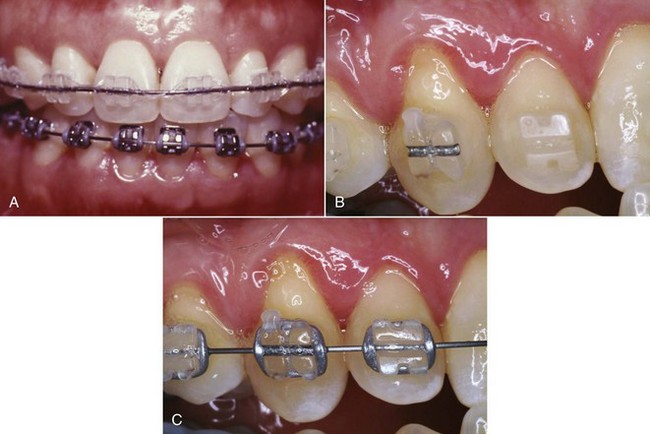
FIGURE 10-28 A, Ceramic twin brackets on the maxillary anterior teeth, with steel brackets on all teeth that are not highly visible. Using ceramic brackets in this way eliminates the possibility of enamel abrasion when teeth contact ceramic brackets in function while maintaining the esthetic benefit of using brackets of this type. B, Ceramic brackets with and without a metal slot, wire out. C, Same brackets with wire in place. Note the similarity of appearance when an archwire is present.
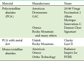
Ceramic brackets, which were first made available commercially in the late 1980s, largely overcome the esthetic limitations of plastic brackets in that they are quite durable and resist staining. In addition, they can be custom-molded for individual teeth and are dimensionally stable, so that the precise bracket angulations and slots of the straight-wire appliance can be incorporated. Several different types of ceramic brackets currently are available (Table 10-2).
Ceramic brackets were received enthusiastically and immediately achieved widespread use, but problems with fractures of brackets, friction within bracket slots, wear on teeth contacting a bracket, and enamel damage from bracket removal soon became apparent. Fractures of ceramic brackets occur in two ways: (1) loss of part of the brackets (e.g., tie wings) during archwire changes or eating and (2) cracking of the bracket when torque forces are applied. Ceramics are a form of glass, and like glass, ceramic brackets tend to be brittle. Because the fracture toughness of steel is much greater, ceramic brackets must be bulkier than stainless steel brackets, and the ceramic design is much closer to a wide single bracket than is usual in steel.
Most currently available ceramic brackets are produced from alumina, either as single-crystal or polycrystalline units. In theory, single-crystal brackets should offer greater strength, which is true until the bracket surface is scratched. At that point, the small surface crack tends to spread, and fracture resistance is reduced to or below the level of the polycrystalline materials. Scratches, of course, are likely to occur during the course of treatment.
Although ceramic brackets are better in this regard than plastics, resistance to sliding has proved to be greater with ceramic than with steel brackets. Because of the multiple crystals, polycrystalline alumina brackets have relatively rough surfaces (Figure 10-29). Even though monocrystalline alumina is as smooth as steel, these brackets do not allow good sliding, perhaps because of a chemical interaction between the wire and bracket material. For this reason, some ceramic brackets now have an integrated metal slot.
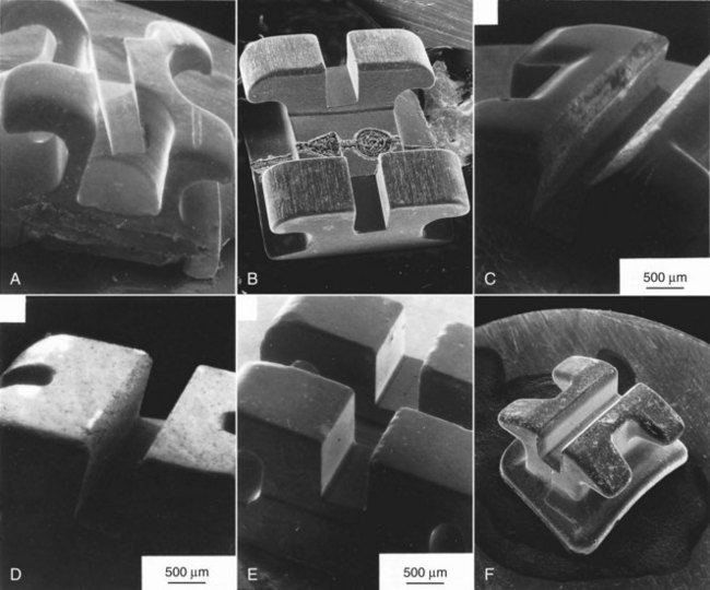
FIGURE 10-29 Scanning electron microscope views of brackets. A, Stainless bracket (Uni-Twin, 3M-Unitek). B, Commercially pure titanium (Rematitan, Dentaurum). C, Polycrystalline alumina (Allure, GAC). D, Polycrystalline alumina (Transcend, 3M-Unitek). E, Monocrystalline alumina (Starfire, A Co.). F, Polycrystalline Zirconia (Toray, Yamaura). Note the smooth surfaces of the monocrystalline alumina and steel brackets compared with the rougher surface of the polycrystalline alumina and Zirconia brackets (which vary from one manufacturer to another). The titanium bracket slot is smooth but not quite as smooth as steel. (Courtesy Dr. R. Kusy.)
Many patients bite against a bracket or tube at some point in treatment. Contact against a steel or titanium bracket causes little or no wear of enamel, but ceramic brackets can abrade enamel quite rapidly. This risk is largely avoided if ceramic brackets are placed only on the upper anterior teeth, which is the location where improved esthetics is most important. Most patients who want the esthetic effect will accept ceramic brackets only where they are most visible and steel or titanium brackets elsewhere.
As noted above in the section on debonding, ceramic brackets also can be a problem when it comes time for bracket removal. Most manufacturers now offer a debonding pliers that is recommended for their ceramic bracket to take advantage of a unique feature engineered into the bracket to help in debonding. An alternative is to use a thermal or laser instrument to weaken the adhesive by heating it, to induce failure within the bonding agent itself. Thermal debonding of this type is quite effective in reducing the chance of enamel damage.17 Unfortunately, it introduces the chance of damaging the tooth pulp unless the heat application is controlled quite precisely, and for that reason has not been widely adopted.
It seems highly probable that composite plastic brackets will become the next advance in brackets in another few years. Composite plastics with better physical properties than any metal already exist and could be used for both brackets and archwires. It is just a matter of overcoming the engineering problems to produce brackets with better mechanical properties, and since the composite plastics can be almost any color, a better appearance is likely to be an additional benefit.
The Straight-Wire Concept in Bracket/Tube Design
Modern edgewise appliances use brackets or tubes that are custom-made for each tooth, with the goal of minimizing the number of bends in archwires needed to produce an ideal arrangement of the teeth, hence the “straight-wire” name (Figure 10-30). In Angle’s terminology for his appliance, first-order bends were used to compensate for differences in tooth thickness, second-order bends to position roots correctly in a mesiodistal direction, and third-order (torque) bends to position roots in a faciolingual direction.
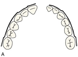
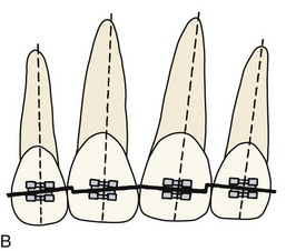
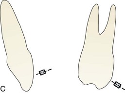
FIGURE 10-30 First-, second-, and third-order bends in edgewise wires. A, First-order bends in a maxillary (left) and mandibular (right) archwire. Note the lateral inset required in the maxillary archwire and the canine and molar offset bends that are required in both. B, Second-order bends in the maxillary incisor segment to compensate for the inclination of the incisal edge of these teeth relative to the long axis of the tooth. C, Third-order bends for the maxillary central incisors and maxillary first molars showing the twist in the archwire to provide a passive fit in a bracket or tube on these teeth. Twist in an archwire provides torque in a bracket; the torque is positive for the incisor, negative for the molar.
Compensations for First-Order Bends: For anterior teeth and premolars, varying the bracket thickness eliminates in-out bends in the anterior portions of each archwire, but an offset position of molar tubes is necessary to prevent molar rotation (Figure 10-31). For good occlusion, the buccal surface must sit at an angle to the line of occlusion, with the mesiobuccal cusp more prominent than the distobuccal cusp. For this reason, the tube or bracket specified for the upper molar should have at least a 10-degree offset, as should the tube for the upper second molar. The offset for the lower first molar should be 5 to 7 degrees, about half as much as for the upper molar. The offset for the lower second molar should be at least as large as for the first molar. Offsets in some typical commercially available appliances are shown in Tables 10-3 and 10-4 (the listed prescriptions are available in most instances from several different manufacturers).
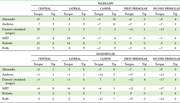
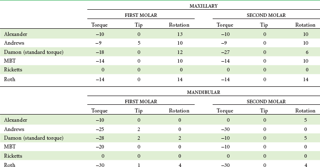
FIGURE 10-31 A, The rhomboidal surface of the upper, and to a lesser extent the lower, molars means that placing a springy archwire through attachments that were flat against the facial surface would produce a mesiolingual rotation of these teeth, causing them to take up too much space in the arch. Compensation requires a bend in the archwire, or placing the tube at an angle offset to the facial surface. B, Rectangular and headgear tubes for the upper first molar and, C, rectangular tube for the lower second molar in a contemporary appliance. Note the offset position of the tubes so that a first-order bend in the wire is unnecessary.
Compensations for Second-Order Bends: In the original edgewise appliance, second-order bends, sometimes called artistic positioning bends, were an important part of the finishing phase of treatment. These bends were necessary because the long axis of each tooth is inclined relative to the plane of a continuous archwire (Figure 10-32). Contemporary edgewise brackets have a built-in tip for maxillary incisor teeth, which varies among the appliances that are now available (see Table 10-3). A distal tip of the upper first molar is also needed to obtain good interdigitation of the posterior teeth (Figure 10-33). If the upper molar is too vertically upright, even though a proper Class I relationship apparently exists, good interdigitation cannot be achieved. Tipping the molar distally brings its distal cusps into occlusion and creates the space needed for proper relationships of the premolars.
FIGURE 10-32 A, A second-order bend, or an inclination of the bracket slot to produce the same effect, is necessary for the maxillary incisors because the long axes of these teeth are inclined relative to the incisal edge. The smaller angle (shown above) is the bracket angulation or the tip. B and C, Malaligned maxillary incisors before and after treatment using straight-wire brackets to facilitate both mesiodistal (tip) and faciolingual (torque) root positioning. (A redrawn from Andrews LF. The straight-wire appliance, explained and compared, J Clin Orthod 10(3):174-195, 1976.)
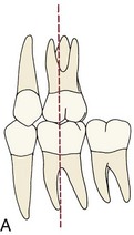
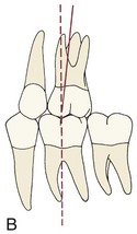
FIGURE 10-33 A distal inclination or tip of the maxillary first molar is important for proper posterior occlusal interdigitation. If the mesiobuccal cusp occludes in the mesial groove of the mandibular first molar, creating an apparently ideal Class I relationship, proper interdigitation of the premolars still cannot be obtained if the molar is positioned too upright (A). Tipping the molar distally (B) allows the premolars to interdigitate properly. (Redrawn from Andrews LF. Am J Orthod 62:296, 1972.)
Compensation for Third-Order Bends: If the bracket for a rectangular archwire is placed flat against the labial or buccal surface of any tooth, the plane of the bracket slot will twist away from the horizontal, often to a considerable extent. With the original edgewise appliance, it was necessary to place a twist in each rectangular archwire to compensate for this. Failure to place third-order bends meant that in the anterior region, the teeth would become too upright, while posteriorly the buccal cusps of molars would be depressed and the lingual cusps elevated (Figure 10-34). Cutting the bracket slot into the bracket at an angle or forming the base so that the face of the bracket is at an angle (which are called placing torque in the bracket or torque in the base, respectively) allows a horizontally flat rectangular archwire to be placed into the bracket slots without incorporating twist bends.
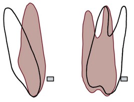
FIGURE 10-34 The plane of a flat rectangular archwire relative to a maxillary incisor and molar is shown in red. To produce the proper faciolingual position of both anterior and posterior teeth, either a rectangular archwire must be twisted (torqued), or the bracket slot must be cut at an angle to produce the same torque effect. Otherwise, the improper inclination shown in red will be produced. Proper torque is necessary not to move teeth but to prevent undesired movement.
The amount of torque recommended in the various appliance prescriptions varies more than any other feature of contemporary edgewise appliances (see Tables 10-3 and 10-4). Although a number of factors are important in establishing the appropriate torque, three are particularly germane to how much torque is used for any particular bracket: (1) the value that the developer of the appliance chose as the average normal inclination of the tooth surface (this varies considerably among individuals and therefore can be different in “normal” samples); (2) where on the labial surface (i.e., how far from the incisal edge) the bracket is intended to be placed (the inclination of the tooth surface varies depending on where the measurement is made, so that an appliance meant to be placed rather gingivally would require different torque values from one placed more incisally); and (3) the expected “play” in the bracket slot between the wire and the slot. As the tables demonstrate, the effective torque produced by undersized rectangular wires is far less than the bracket slot prescription might lead one to expect.
Contemporary Straight-Wire Brackets and Tubes
Self-Ligating Brackets: Placing wire ligatures around tie wings on brackets to hold archwires in the bracket slot is a time-consuming procedure. The elastomeric modules introduced in the 1970s largely replaced wire ligatures for two reasons: they are quicker and easier to place, and they can be used in chains to close small spaces within the arch or prevent spaces from opening.
It also is possible to use a cap or clip, attached over the bracket or built into the bracket itself, to hold wires in position. Three types of self-ligating mechanisms built into the bracket are available at present (with more probably on the way): a springy latching cap, springy retaining clips in the bracket walls, and rigid latching caps (Figure 10-35). A variety of claims have been made as advantages of self-ligating brackets, but as we have pointed out in Chapter 9, it is clear now that almost all of these are incorrect when clinical outcomes are reviewed. Reduction of friction, the most advertised claim, is true in laboratory testing but does not lead to less resistance to sliding a bracket along a wire or a wire through a bracket. A recent summary of claims versus evidence concluded that self-ligating brackets save a little time in ligation but do not produce a saving of treatment time or better results.18
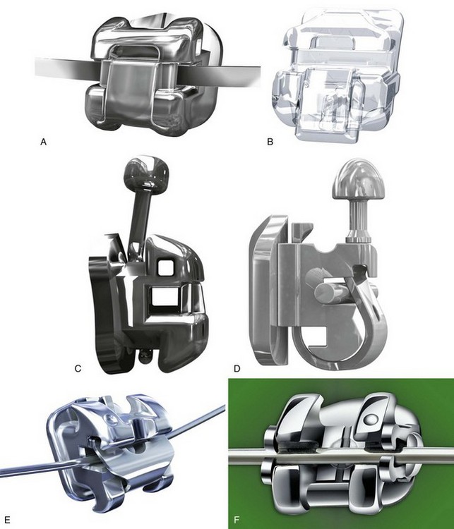
FIGURE 10-35 Self-ligating brackets have either a rigid clip (Damon, others), spring clip (Innovation, Speed), or retaining springs (SmartClip™) to hold an archwire in the bracket slot. A and B, Demonstration of an open bracket with a rigid slot (A, Damon-Q) and the clip closed in a ceramic bracket of the same design (B, Damon Clear). Esthetic nonmetal brackets are available now in most self-ligating bracket designs. C, Side view of the Damon-Q bracket showing the accessory horizontal slot and the rigid clip. D, Side view of the Speed bracket which utilizes a NiTi spring clip. E, The Innovation-R bracket. F, The SmartClip™ bracket with retaining springs. (A to C, courtesy Ormco Corporation; D, courtesy SPEED System Orthodontics, Cambridge, Canada; E, courtesy GAC; F, courtesy 3M Unitek.)
This should not be taken to mean that there is anything wrong with the brackets. The problem is the advertising, not the product. As a group, the self-ligating brackets perform quite nicely, with no evidence that their latching mechanism makes any significant difference. It is important, however, that a self-ligating bracket is made so that when stabilization rather than tooth movement is needed or the latching mechanism has difficulty in holding a rectangular torquing wire in place, an archwire can be tied tightly in place with an external steel ligature.
Individually Customized Brackets: Because of the marked individual variations in the contour of the teeth, no appliance prescription can be optimal for all patients, and compensatory bends in finishing archwires often are necessary. Custom brackets for the facial surface of teeth offer the prospect of eliminating almost all archwire bending (i.e., they could provide the perfect straight wire appliance). The Insignia system now marketed by Ormco (Ormco/Sybron, Glendora, CA) makes just this claim.
Whether custom brackets are to be made for the facial or lingual surfaces, the technology is much the same. The first step is a 3-D scan with at least 50 micron resolution, now of dental casts on a laboratory bench but perhaps directly in the mouth in the future. This digital information is used to precisely cut each bracket using computer-aided design/computer-aided manufacturing (CAD/CAM) technology, so that the slot for each bracket has the appropriate thickness, inclination, and torque needed for ideal positioning of that tooth (Figure 10-36), and archwires with an arch form established for that patient are supplied. The result for custom brackets on the facial is “the ultimate straight-wire appliance,” with wire bending reduced to a minimum. Preliminary data indicate that treatment time is reduced in comparison to treatment with conventional prescription brackets, but that some adjustment of the final archwires still is required.
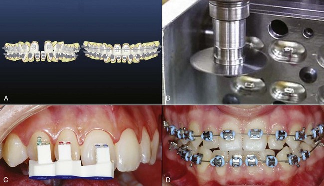
FIGURE 10-36 The Insignia system is built around the use of a custom prescription bracket for each individual tooth, coupled with custom archwires with that patient’s individual arch form, to produce the “ultimate straight-wire appliance.” A PVS impression is used to obtain accurate dental casts, which are scanned into computer memory. A, This data set is used to place virtual brackets on each tooth and develop a template of the change needed to obtain ideal occlusion. B, The digital data are used to mill a custom prescription slot for each bracket that incorporates the in-out, tip and torque needed to position each tooth. C, Then bonding jigs are fabricated so that each bracket can be placed in the planned location. D, The appliance in the mouth with an archwire in place. (Courtesy Ormco Corporation.)
Individualized custom brackets must be attached to the teeth with precision equal to that used in making them, so an indirect bonding system with an accurate placement template is required. What happens when one of the custom brackets is lost and requires replacement and rebonding, or is loose and requires rebonding? Because the specifications for each bracket can be maintained in computer memory, it is possible to obtain a replacement bracket and bonding template within 2 to 3 weeks. Rebonding a loose bracket is done most efficiently by using the original bonding template, which should be kept with the patient’s records for this possible re-use.
At present, however, that is not the biggest problem. Even a set of modern CAD/CAM brackets formed on individual dental casts is still focused only on dental relationships and so, for example, the Class II patient who requires slightly more upright maxillary incisors and more proclined lower incisors would still receive brackets with “ideal” incisor inclinations. It remains important to introduce coordination with the patient’s individual skeletal and soft tissue pattern into this type of design. Attempts are being made now to integrate images of tooth–lip relationships into the data base for fabrication of the custom brackets.
Lingual Appliances: A major objection to fixed orthodontic appliances always has been their visible placement on the facial surface of the teeth. This is one reason for using removable appliances and is the major reason for the current popularity of clear aligners in treatment of adults. The introduction of bonding in the 1970s made it possible to place fixed attachments on the lingual surface of teeth to provide an invisible fixed appliance, and brackets designed for the lingual surface were first offered soon after bonding was introduced, but there were multiple problems in producing a bracket that intruded only minimally into tongue space and was at least reasonably easy to use. In the United States, most orthodontists who experimented with the lingual appliances available in the 1980s abandoned this approach as more trouble than it was worth, and lingual appliance treatment all but disappeared until quite recently.
Recent progress in Europe and Asia has made lingual orthodontics much more widely used there. One successful European approach that now is marketed in the United States (Incognito, 3M-Unitek) is to fabricate a custom precious metal pad that covers a large area on the lingual surface of each tooth and then attach low-profile brackets to the custom pads (Figure 10-37). These brackets, designed so the archwire can be inserted from the top, are the same for each tooth; wire bending is eliminated by using wire-bending robots to form the archwires.19 Computer-controlled wire-bending devices are particularly applicable to the fabrication of the lingual archwires but also can be used with labial appliances (see later).
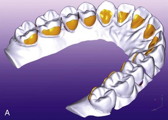
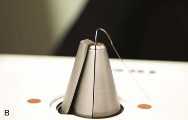
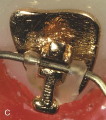
FIGURE 10-37 A, The approach for one successful custom lingual appliance (Incognito, 3M-Unitek, Monrovia, CA) is based on laser scans of casts after the teeth are separated and set in ideal position. The location of the custom bracket pad for each tooth is established, and wax patterns are made for (B) gold castings of custom bracket pads for each tooth. The use of these custom pads greatly improves retention of the bonded lingual brackets. A standard bracket (not individualized for each tooth) that allows vertical insertion of archwires and the use of elastomeric or wire ligatures (C) is attached to the custom pads, and the completed appliance (D) is supplied ready for indirect bonding. Note that extraction of maxillary first premolars is planned for this patient. (Courtesy Dr. D. Wiechmann.)
A major test for any of the computer-assisted appliance systems is the accuracy with which the planned outcome (established during manufacture of the customized appliance) actually is achieved. A recent study, using a new method for analyzing the difference between the computer template and the final result, shows that Incognito outcomes are quite accurate representations of the template, except that second molars are not positioned as precisely as the other teeth (Figure 10-38).20 Feedback of that type is needed for all of the computer-assisted approaches, both to improve the accuracy of the system and to allow better evaluation of the method.
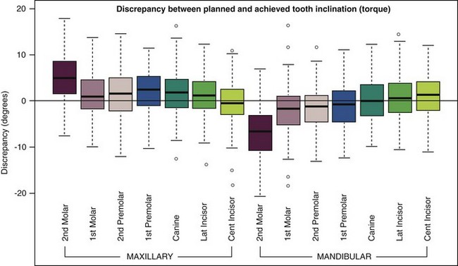
FIGURE 10-38 Box plots depicting the difference between the planned and achieved inclination (torque) by tooth type in a sample of 94 patients treated using the Incognito lingual appliance (from TopService GMBH, Bad Essen, Germany). Each box shows the median difference from the plan (dark line) and the amount of deviation for the median 50% of the patients. Range and extreme outliers are shown by the whiskers and small circles, respectively. Note that for most of the sample and for all teeth except second molars, mean inclination differences were very small and differences >6 degrees of inclination were rare. (Courtesy Dr. D. Grauer.)
Making Sensible Appliance Choices Based on Patient Preference: There are considerable differences in what patients indicate is the most attractive appliances, the one they would prefer to have.21 Most notably, this is related to patient age, but there are some minor gender differences. For 9 to 11 year olds, the preference is either for shaped brackets like Wildsmiles (Wildsmiles Braces, Omaha, NE) with or without colored elastomeric ties or for mini-twin brackets with colored elastomeric ties. Inconspicuous esthetic brackets are not a high priority for this group, so a durable appliance that provides excellent control and is modestly priced is appropriate. In the 12 to 14 age group, clear aligners and esthetic brackets are more highly prized, but mini-twin brackets with colored ties and the shaped brackets all are rated similarly. Clear aligners often are not practical with partially erupted teeth and continuing growth.
For the 15 to 17 year olds, clear aligners and esthetic brackets with a clear wire (see discussion later) are considered most attractive. For this group, clear aligners can make sense because the permanent teeth are fully erupted and rapid growth is completed. Adults prefer lingual appliances, clear aligners, and esthetic brackets, especially when combined with a clear wire. The spectrum changes from unique and colorful for young children to esthetic appliances with older adolescents and adults. With this combination of acceptable alternatives, it is possible to meet esthetic demands and accomplish the biomechanics for each individual case for almost every patient.
Arch Form and Archwire Fabrication
Selection of Arch Form for Individual Patients: As another contributor to increased efficiency, preformed archwires are an important part of the modern edgewise appliance, whether individualized custom brackets are used or not. When nickel-titanium (NiTi) and beta-titanium (beta-Ti; TMA) wires are needed, there is no choice but to use preformed archwires because these wires are almost impossible to shape to arch form without special tools. What arch form should be employed?
The concept that dental arch form varies among individuals is driven home to most dentists in full denture prosthodontics, where it is taught that the dimensions and shape of the dental arches are correlated with the dimensions and shape of the face. The same variations in arch form and dimensions of course exist in the natural dentition, and it is not the goal of orthodontic treatment to produce dental arches of a single ideal size and shape for everyone.
The basic principle of arch form in orthodontic treatment is that within reason, the patient’s original arch form should be preserved. Most thoughtful orthodontists have assumed that this would place the teeth in a position of maximum stability, and long-term retention studies support the view that posttreatment changes are greater when arch form is altered than when it is maintained (see Chapter 17).
As a more general guideline, if the maxillary and mandibular arch forms are incompatible at the beginning of treatment, the mandibular arch form should be used as a basic guide. In many patients with Class II malocclusion, the maxillary arch is narrow across the canines and premolars, and should be expanded to match the lower arch as overjet is reduced. Obviously, this guideline would not apply when mandibular arch form is distorted. That can happen in a number of ways, the most common being lingual displacement of the mandibular incisors by habits or heavy lip pressures, and unilateral drift of teeth in response to early loss of primary canines or molars. Although some judgment is required, the arch form desired at the end of orthodontic treatment should be determined at the beginning, and the patient’s occlusal relationships should be established with this in mind.
An excellent mathematical description of the natural dental arch form is provided by a catenary curve, which is the shape that a loop of chain would take if it were suspended from two hooks. The length of the chain and the width between the supports determine the precise shape of the curve. When the width across the first molars is used to establish the posterior attachments, a catenary curve fits the dental arch form of the premolar-canine-incisor segment of the arch very nicely for most individuals. For all patients, the fit is not as good if the catenary curve is extended posteriorly, because the dental arch normally curves slightly lingually in the second and third molar region (Figure 10-39). Most of the preformed archwires offered by contemporary manufacturers are based on a catenary curve, with average intermolar dimensions. Modifications to accommodate for a generally more tapering or more square morphology are appropriate, and the second molars must be “tucked in” slightly.
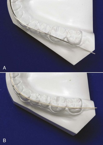
FIGURE 10-39 A, Preformed archwire with catenary arch form on a lower dental cast from an untreated patient. Note the good correspondence between the arch form and the line of occlusion, except for the second molars. B, The Brader arch form for preformed archwires is based on a trifocal ellipse, which slightly rounds the arch in the premolar region compared with a catenary curve and constricts it posteriorly. An archwire formed to the Brader curve fits much better in the second molar region for this untreated patient than a catenary curve.
Another mathematical model of dental arch form, originally advocated by Brader and often called the Brader arch form, is based on a trifocal ellipse. The anterior segment of the trifocal ellipse closely approximates the anterior segment of a catenary curve, but the trifocal ellipse gradually constricts posteriorly in a way that the catenary curve does not (Figure 10-39, B). The Brader arch form therefore will more closely approximate the normal position of the second and third molars. It also differs from a catenary curve in producing somewhat greater width across the premolars.
Recently, several manufacturers have offered preformed archwires that appear to be variations of the Brader arch, with advertisements that suggest these wires are more compatible with expansion therapy than conventional arch forms. Expansion across the premolars often is thought to have esthetic advantages; whether the modified arch form to produce this has any effect on stability is unknown. More refined mathematical descriptions of typical human arch forms now are available,22 and it is likely that better mathematical models will improve the preformed archwires available in the near future.
It is important to keep in mind that neither the ligation method nor the prescription adjustments placed in straight-wire brackets have anything to do with arch form, which is still established by the shape of the archwires. Arch form is particularly important during the finishing stage of treatment, when heavy rectangular archwires are employed. Preformed archwires are best considered as “arch blanks” and sometimes are listed in the catalogs in that way. The name is appropriate, since this properly implies that a degree of individualization of their shape will be required to accommodate the needs of patients.
Wire-Bending Robots: Another approach to the goal of reducing the amount of clinical time spent bending archwires is to use a computer-controlled machine to shape the archwire as desired. If the effort to fabricate a complex archwire were eliminated, inexpensive “plain vanilla” brackets could be used instead of going to the trouble of producing custom brackets with elaborate prescriptions. A less complex bracket also could be smaller and have a lower profile.
In lingual orthodontics, the scanned casts needed for fabrication of custom bracket pads also provide the data needed to generate computer-fabricated archwires (Figure 10-40). For labial orthodontics, SureSmile (OraMetrix, Richardson, TX) uses data acquired via an intraoral scan to shape finishing archwires to the desired arch form and adjust it at each bracket to provide correct in-out, angulation, and torque bends.
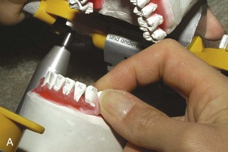
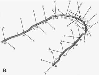
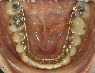
FIGURE 10-40 Archwires for the Incognito lingual appliance are formed with a wire-bending robot, using an ideal setup of the teeth that were scanned in preparation of the bracket pads. A, Ideal setup in preparation on an articulator. B, Archwire coordinates for using a wire-bending robot to form an archwire. C, Archwire in place after robotic fabrication. (Courtesy Dr. D. Wiechmann.)
In the SureSmile technique, it is recommended to obtain a first intraoral scan of the patient’s dentition so that the company can produce a digital setup of the finished result. The orthodontist can view and modify this as an aid in planning treatment. The first step in treatment is to bond non-customized brackets—the only requirement is that the characteristics of the brackets are known—and the teeth in both arches are aligned and leveled with light round wires as in typical treatment (see Chapter 14). At that point, a new intraoral scan is obtained and a second setup is produced in which the finishing details are incorporated. Once this is approved by the orthodontist, a robot forms superelastic rectangular archwires (using steel, beta-Ti, or NiTi as the archwire material as specified by the doctor) that are sent to the orthodontist, and these wires bring the teeth to their final positions (Figure 10-41).
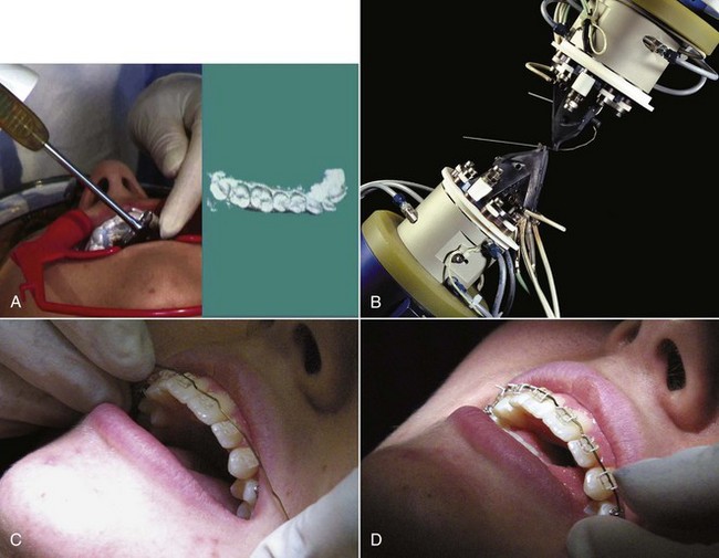
FIGURE 10-41 In the SureSmile system, an intraoral scan of the patient’s teeth is used (instead of a scan of dental casts) to provide information for archwire preparation. A, The intraoral scanning device and its output on a computer screen. B, A wire-bending robot making the precise bends in a custom archwire. In this system, precise positioning of brackets and special bracket prescriptions are not necessary because the robot can bend the wire as desired. For this patient (C and D), bends compensating for discrepancies in bracket height and root positioning bends for the maxillary central incisors can be seen before and after the archwire is tied in. (Courtesy Dr. R. Sachdeva.)
In a study carried out at the University of Indiana, the first to provide good data for SureSmile outcomes in nonextraction treatment,23 a group of 63 conventionally finished patients were compared with 69 SureSmile patients treated in the same office by the same clinician. The SureSmile group had a significantly shorter time in fixed appliances (mean of 23 versus 32 months) and a trend toward lower (better) scores on cast analysis that was not statistically significant. This must be interpreted with caution because the two groups had a somewhat different makeup: the SureSmile group had fewer complex malocclusions than the conventional group and a lower proportion of males (who have been shown in previous studies to generally finish with higher cast analysis scores). Although the SureSmile group had better scores for alignment/rotation correction and fewer interproximal spaces, the conventional group had better scores for both faciolingual (torque) and mesiodistal (tip) root angulation. The study concluded that the shorter treatment time with SureSmile was due at least in part to less severe malocclusions and less detailed finishing and that a randomized clinical trial would be needed to determine whether the use of computer-formed finishing wires really reduced treatment time for comparable outcomes. As we have noted previously, rectangular superelastic archwires provide lower moments within brackets than are ideal for both tip and torque, and although these were specified by the doctor, their use by SureSmile also may have contributed to the poorer root positioning.
Clear Polymer Archwires: Orthodontic archwires formed from clear polymers now are becoming available. They offer two potential advantages over stainless steel or titanium: better esthetics because the wire can be clear or the same color as the teeth, so that the wire becomes almost invisible when used with ceramic brackets (Figure 10-42) and physical properties that equal or exceed those of metal archwires.
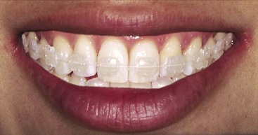
FIGURE 10-42 A glass-reinforced clear polymer archwire in a ceramic bracket is almost invisible but, of course, is subject to the limited smoothness of the bracket slot. Archwires of this type in a bracket also made from a clear polymer probably will be the esthetic labial appliance of the future.
Clear polymer archwires currently are being developed using two different approaches—a formable and a nonformable alternative. Burstone et al are pursuing the first approach using a polyphenylene polymer (Primospire, Solvay Advanced Polymers, Alpharetta, GA).24 This material extruded as round and rectangular cross-section arches. It has properties similar to small dimension beta-Ti wires and formability similar to stainless steel wires.
The second approach is being advocated by SimpliClear Braces (Biomers, Singapore), who fabricate archwires from a polymer resin matrix reinforced with glass fibers. A specially modified methacrylate resin serves as the polymer matrix material. These wires are available in round and rectangular cross-sections, and can be paired with esthetic pretorqued and preangulated brackets of the practitioner’s choice. Although this clear wire is not formable clinically, auxiliaries like rotating wedges or bracket repositioning can be used to treat simple cases without custom wires.
For more complex cases, a series of preformed custom wires are made using either digital images from scans of dental casts or intraoral scans. This series is designed individually for every patient based on the treatment plan provided by the orthodontist prior to the onset of treatment. The wires are designed to sequentially and incrementally move teeth toward a predetermined position (Figure 10-43). In theory, they should provide better control than a sequence of clear aligners—conceptually, this is a fixed appliance version of Invisalign—but their clinical performance has not yet been thoroughly evaluated. This clear wire also can be incorporated into retainers as the labial bow to provide an esthetic solution that allows settling with good stability (see Figure 17-8, E).
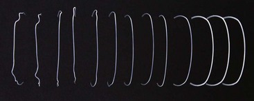
Summary: At this point, it seems likely that most fixed orthodontic appliances of the not-too-distant future will be individualized using scans of the tooth surfaces and computer technology. It is still too soon to tell, however, whether the usual approach will be custom brackets that allow the use of preformed archwires with little or no manual wire bending, minimally compensated (and less expensive) brackets that are used in connection with a wire-bending robot, or a sequence of nonadjustable custom wires produced for that patient.
Temporary Anchorage Devices
The rapid development and commercialization of bone screws and miniplates for use as orthodontic anchorage devices has resulted in a remarkable diversity in these items. The key characteristics of any orthodontic temporary anchorage device (TAD) are (1) its short- and long-term stability, the major indicator of success or failure, and (2) its ease of use, which includes both its placement and the features of the attachment that extends into the oral cavity. The goal here is to discuss what has been learned about desirable and undesirable features of this increasingly important part of the orthodontist’ armamentarium.
Bone Screws
A wide variety of bone screws for use as intraoral TADs now are available. Three reasonably typical screws for use as TADs are shown in Figure 10-44, and desirable characteristics are summarized in Box 10-2. Although stainless steel screws were marketed initially, most now are formed from titanium (purity grades I to IV) to take advantage of its greater biocompatibility.
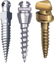
FIGURE 10-44 Bone screw types for use as orthodontic TADs. Note the differences in the shape of the head and collar, the shape (form) of the screw and the screw threads, and the pitch (separation) of the screw threads. Each of these screws requires a special driver that fits the base of the head, and the method for attaching a wire or spring to the screw is different in each case. Development of the optimum form of a bone screw for orthodontic applications remains a work in progress.
Stability: Short-term or primary stability is determined by mechanical retention of the screw in bone, which depends on bone properties, the engineering design of the screw, and placement technique. Long-term or secondary stability is defined by the biologic union of the screw to the surrounding bone. It is determined by the implant surface, bone characteristics, and bone turnover (especially in the context of cortical versus medullary bone) and is affected by the implant surface and the mechanical system used. To obtain good secondary stability it is important to limit micromovements that could lead to bone resorption and formation of a fibrous capsule. Over time, primary stability decreases while secondary stability increases; clinical stability is the sum of primary and secondary stability and is the major factor in clinical success (Figure 10-45).
FIGURE 10-45 Primary stability, which is created by mechanical retention of a bone screw in bone, is maximal immediately after the screw is placed and declines rapidly as bone remodeling occurs around the screw. Secondary stability, created by a biologic union between the screw and bone, increases over time. Clinical stability is the sum of primary and secondary stability. Note that clinical stability declines to a minimum at about 2 weeks postinsertion, then (if all goes well) stabilizes at a somewhat larger value than the initial primary stability at about 6 weeks.
Factors in stability/success that have been shown to be important are:
• The pitch of the screw threads (i.e., how close the threads are to each other). A tight pitch means the threads are close, a loose pitch means they are farther apart. The denser the bone, the closer the threads should be. It has become apparent that most of a screw’s resistance to being dislodged comes from contact with cortical bone and relatively little from medullary bone. Because the layer of cortical bone is thin in the dental alveolus, a tighter pitch of the threads near the head of the screw gives greater contact with the cortical bone, higher pull-out strength, and better primary stability.25
• The length of the screw. If the amount of contact with cortical bone is the major factor in stability, while the amount of contact with medullary bone makes little difference, it seems logical that short screws should perform as well as longer ones. In fact, short screws, much shorter than those used initially, can be quite effective.26 Currently, the length of available bone screws for intraoral use ranges from 5 to 12 mm, but shorter ones, between 6 and 8 mm, are used more often. A long screw that passes all the way through the alveolus to reach cortical bone on the other side does provide greater stability,27 but in most instances this is not worth the greater invasiveness.
• The diameter of the screw. A screw that is to be placed into the alveolar process must be narrow enough to fit between the teeth. Critical variables are how much clearance is needed between the screw and the tooth roots and the extent to which reducing the diameter of the screw decreases its resistance to fracture or displacement.28 Bone screw TADs currently on the market can be as narrow as 1.3 mm and as wide as 2 mm. The success rate drops when the screw is narrower than 1.3 mm. Within the 1.3 to 2.0 mm diameter range, stability and survival are much more strongly related to the amount of cortical bone contact rather than the screw diameter, but a larger diameter screw does show better primary stability when heavy force is applied. At this point, the data suggest that root proximity is not a major factor in long-term stability of the screw29 and that, at least in dogs, penetration of the periodontal ligament does not lead to ankylosis.30 In humans, the possibility of ankylosis as the screw socket heals cannot be ruled out, so avoiding contact with tooth roots probably is important for adolescent patients even if it does not affect stability of the TAD.
• The taper of the screw. Data from animal experiments show greater microdamage to cortical bone with conical screws that are thicker than cylindrical screws near the screw head.31 This might affect secondary stability even though primary stability is greater.
• The form of the tip (see Figure 10-45). All miniscrews are self-tapping (i.e., they create their own thread as they advance). There are two self-tapping designs: thread-forming and thread-cutting. The difference is the presence of a cutting flute on the tip of the thread-cutting screw. A thread-forming screw compresses the bone around the thread as the screw advances, obtains better bone-to-screw contact, and is better adapted for use with alveolar bone. The flutes on a thread-cutting screw improve penetration into denser bone.32 It appears that thread-cutting screws perform better in the mandibular ramus, mandibular buccal shelf, zygomatic buttress, and palate.
• The surface of the threaded part of the screw. Although some animal data suggest that a roughened (sand-blasted and/or acid-etched) surface increases primary stability and allows immediate loading,33 the screw’s surface characteristics do not seem to be a major influence on clinical stability.34
For a more detailed review of the factors that influence clinical stability and success rates, see Crismani et al.35
Ease of Use: A second important aspect of any orthodontic TAD is its ease of use. This has two components: how easy or difficult it is to place the screw (Figure 10-46) and how easy it is to use the exposed screw head as an attachment for springs or wires.
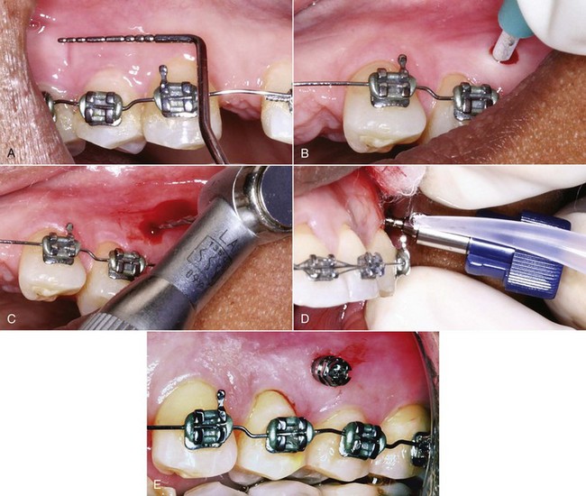
FIGURE 10-46 The sequence of steps in insertion of an alveolar bone screw. A, Marking the location for the screw, which should be in gingiva rather than mucosa if possible but must be high enough to accommodate any vertical changes in tooth position. Note the bends in the archwire that were used to create some root separation in the area where the screw is to be placed. B, Use of a tissue punch, which is needed if a hole is to be drilled into the bone or if the screw is placed through mucosa, but may not be needed for a screw placed through gingiva. C, Drilling a pilot hole through the cortical plate (which is needed only if the cortical bone is relatively thick). D, Placing the screw, which will then be screwed into position using a special driver shaped to fit the screw head. E, The screw in position, ready for use.
Factors in ease of screw placement include:
• Whether a pilot hole is needed. Self-drilling screws do not need a pilot hole beyond the cortical plate and can penetrate the cortical plate if it is thin.36 Screws of this type now have largely replaced screws that do require a pilot hole because they can be used either way, with the decision being made at the time of insertion. If the cortical plate is difficult to penetrate, a pilot hole may be needed to prevent high insertion torque and potential for screw fracture.
• Whether a tissue punch is needed. A tissue punch through the gingiva is rarely needed unless a pilot hole is to be drilled but frequently is needed in unattached tissue to keep gingival tissue from wrapping around the screw thread.
• The ease or difficulty of turning the screw as it is inserted, while keeping pressure on it. An important factor in this is the insertion torque, which is influenced both by the mechanical factors discussed above that affect stability and by bone density and cortical thickness. Although high insertion torque increases primary stability, it can lead to fracture of the screw, increased microdamage to the bone and decreased secondary stability. Moderate insertion torque provides enough primary stability without causing excessive bone compression and subsequent remodeling. A driver made to fit around the head of the specific screw type is needed for insertion, and some systems offer a torque-controlled instrument for placement of their bone screws (Figure 10-47).
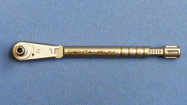
A major factor affecting the ease of attaching springs or wires is whether direct or indirect anchorage is to be used. In direct anchorage the force is applied directly to a tooth or group of teeth from a bone screw. To do this, it is desirable to fit NiTi springs over the screw head without having to tie them, which means that the screw head should have an attachment area that will lock into place. With indirect anchorage, the bone screw anchors a tooth or group of teeth to which force is applied, and the goal is to prevent movement of these teeth. Even though some indirect anchorage can be gained by a ligature tie from the bone screw to the anchored tooth or teeth, indirect anchorage normally requires the screw head to have a rectangular slot or a hole where a wire can be locked or bonded in place (Figure 10-48).
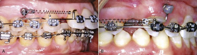
FIGURE 10-48 A, An alveolar bone screw used for direct anchorage usually serves as the attachment point for a superelastic NiTi spring, as in this use to retract protruding maxillary incisors. B, Bone screws also work well for indirect anchorage, when a rigid attachment from the screw is used to prevent movement of anchor teeth, as in this patient in whom the maxillary posterior teeth are being moved forward via a spring to the stabilized canine.
In summary, the desirable characteristics of a bone screw TAD are listed in Box 10-2. Since no one device has all of them, this serves as a guide to the trade-offs in selecting the screw and suggests that efficient practice requires having more than one type of bone screw available.
Miniplates
Miniplates usually are placed at the base of the zygomatic arch (see Figure 15-10), but can be used in other locations as well (Figure 10-49). They are held in place by multiple screws and have only a small connector extending into the mouth. The ideal location for the connector is at the junction of the fixed gingival tissue and loose mucosa.
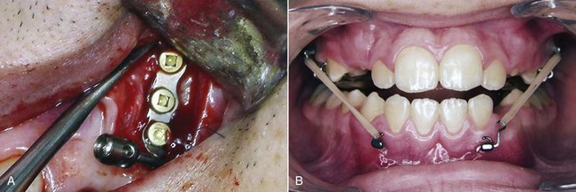
FIGURE 10-49 A, A miniplate placed at the base of the zygomatic arch requires creating a flap to expose the bone and must be contoured so it fits closely to the one surface. In this location it is above the roots of the teeth, and is ideally positioned as an anchor for mesiodistal movement of the maxillary teeth. B, A miniplate on the mandible to serve as an attachment for Class III elastics. Note that a segment of wire has been used on one side to move the attachment point so that the elastic will not impinge on the gingiva. Being able to move the attachment point is a major advantage of using miniplates rather than single screws.
As with screws, the key characteristics are stability and ease of use. For miniplates, the two major determinants of stability are:
• The number of screws with which the plate is attached. The success rate for plates of four designs placed by the same operator is shown in Figure 10-50. It appears that three screws provide more stability than two, but nothing additional is gained with four screws.
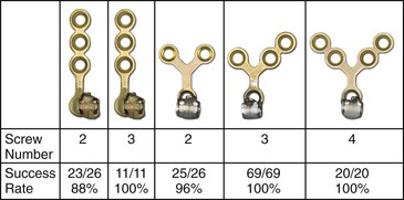
FIGURE 10-50 Success rates for plates of different designs and number of screws placed by the same operator. Note that success rates were quite high in all these applications, but failures were more likely with two screws than three, and no better with four screws than three, so three screws are preferred. (Courtesy Dr. T. Wu.)
• The age of the patient. As Table 10-5 shows, the number of failures with miniplates in both North Carolina and Belgium was much greater in young patients who had not yet entered puberty and in the mandibular arch where miniplates were used only in young patients. This is a particularly pertinent observation with regard to use of Class III elastics to maxillary and mandibular miniplates (see Chapter 13): bone maturity does not reach the level for good retention of the screws before approximately age 11 (obviously, maturational rather than chronologic age).
TABLE 10-5
| University of North Carolina (UNC) | Université de Catholique de Louvain (UCL) | |
| Number of miniplates | 59 | 141 |
| Number of failures | 4 (7%) | 11 (8%) |
| Due to mobility | 2 | 5 |
| Soft tissue ulceration | 0 | 4 |
| Anchor breakage | 1 | 2 |
| Poor location | 1 | 0 |
| In growing patients | 3 (75%) | 8 (73%) |
| In adults | 1 (25%) | 3 (27%) |
| In mandible | NA | 6 (56%) |
Adapted from Cornelis MA, Scheffler NR, Nyssen-Behets C, et al. Am J Orthod Dentofac Orthop 133:8-14, 2008.
Miniplates are well accepted by patients and providers and are a safe and effective adjunct for complex orthodontic treatment.37 Because it is necessary to reflect a flap to place miniplates and then suture the soft tissue incision, their surgical placement is significantly more difficult than screws. It is important to contour the miniplates to fit closely against the bone of the base of the zygoma and also to maintain bone contact at the point of emergence to prevent excessive moments against the proximal screw. As a general rule, orthodontists can place bone screw TADs into alveolar bone quite satisfactorily, but miniplates are better done by those with more extensive surgical training. From the surgeon’s perspective, this is a relatively short surgical procedure that can be performed under local anesthesia without significant complications.38
Once the plates are in place, however, they are as easy for the orthodontist to use as alveolar TADs, perhaps easier because heavier force can be used. Compared to individual alveolar screws, miniplates have three major advantages:
• The amount of force that the miniplate can tolerate is significantly larger because the plate is held by multiple screws and usually is placed in an area with thicker cortical bone.
• If the miniplate has a locking mechanism (as it should), the direction of pull can be changed readily and the source of the force can be moved a considerable distance by extending wire hooks from the intraoral fixture (Figure 10-51; also see Figure 10-48). This also can be done with individual screws that have a slot for a wire extension, but putting a force on the extension introduces a moment that can overtighten or loosen the screw. With multiple screws holding the miniplate, this is not a problem.
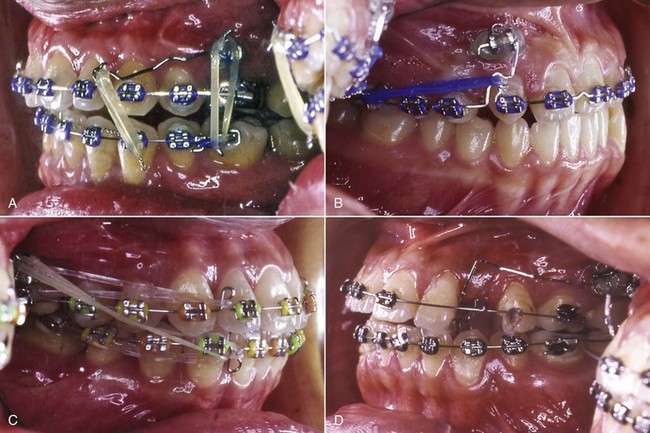
FIGURE 10-51 A to D, A variety of attachment points can be created with wire extensions from miniplates, as illustrated in this series of variations in force directions using miniplates in the same location at the base of the zygoma. (Courtesy Dr. T. Wu.)
• The miniplates can be placed well above the roots of the maxillary teeth, so that an interdental screw does not become a barrier to moving all the teeth mesially or distally. With individual interdental screws, relocation is necessary to accomplish distal movement of teeth anterior to the screw or mesial movement of teeth posterior to the screw.39
In comparing alveolar TADs to miniplates (Box 10-3), a reasonable conclusion is that individual screws are less invasive and are indicated whenever they can provide adequate anchorage. This is the case when a few teeth need to be repositioned. A long screw at the base of the alveolar arch can be used if intrusion of maxillary posterior teeth (which requires light force) is desired (see Chapter 18). For more complex and extensive movement of multiple teeth, with distalization of an entire dental arch the best example, miniplates offer better control and are less likely to loosen or need to be replaced.
References
1. Graber TM, Rakosi T, Petrovic AG, eds. Dentofacial Orthopedics with Functional Appliances. St. Louis: Mosby, 1997.
2. Sheridan, JJ, Ledoux, W, McMinn, R. Essix appliances: minor tooth movement with divots and windows. J Clin Orthod. 1994;28:659–665.
3. Sheridan, JJ, Armbruster, P, Nguyen, P, et al. Tooth movement with Essix molding. J Clin Orthod. 2004;38:435–441.
4. Kravitz, ND, Kusnoto, B, BeGole, E, et al. How well does Invisalign work? A prospective clinical study evaluating the efficacy of tooth movement with Invisalign. Am J Orthod Dentofac Orthop. 2009;135:27–35.
5. Begg, PR, Kesling, PC. Begg Orthodontic Theory and Technique, 3rd ed. Philadelphia: WB Saunders; 1977.
6. Parkhouse, RC. Tip-Edge Orthodontics. Edinburgh/New York: Mosby; 2003.
7. Andrews, LF. Straight Wire: The Concept and Appliance. San Diego: LA Wells; 1989.
8. Al-Saleh, M, El-Mowafy, O. Bond strength of orthodontic brackets with new self-adhesive resin cements. Am J Orthod Dentofac Orthop. 2010;137:528–533.
9. Chapman, JA, Roberts, WE, Eckert, GJ, et al. Risk factors and severity of white spot lesions during treatment with fixed orthodontic appliances. Am J Orthod Dentofac Orthop. 2010;138:188–194.
10. Shungin, D, Olsson, DI, Persson, M. Orthodontic treatment-related white spot lesions: a 14-year prospective quantitative follow-up, including bonding material assessment. Am J Orthod Dentofac Orthop. 2010;138:136e1–136e8. [discussion 136-137].
11. Benson PE, Parkin N, Millett DT, et al. Fluorides for the prevention of white spots on teeth during fixed brace treatment. The Cochrane Database of Systematic Reviews 2007 Issue 1; The Cochrane Collaboration. John Wiley and Sons, Ltd.
12. Rogers, S, Chadwick, B, Treasure, E. Fluoride-containing orthodontic adhesives and decalcification in patients with fixed appliances: a systematic review. Am J Orthod Dentofac Orthop. 2010;138:390.e1–390.e8. [discussion 390-391].
13. Baturina, O, Tulecki, E, Guney-Altay, O, et al. Development of a sustained fluoride delivery system. Angle Orthod. 2010;80:1129–1135.
14. Guzman-Armstrong, S, Chalmers, J, Warren, JJ. White spot lesions: prevention and treatment. Am J Orthod Dentofac Orthop. 2010;138:690–696.
15. Murphy, TC, Willmot, DR, Rodd, HD. Management of postorthodontic white lesion with microabrasion: a quantitative assessment. Am J Orthod Dentofac Orthop. 2007;131:27–33.
16. Kolokitha, OE, Kaklamanos, EG, Papadopoulos, MA. Prevalence of nickel hypersensitivity in orthodontic patients: a meta-analysis. Am J Orthod Dentofac Orthop. 2008;134:722.e1–722.e12. [discussion 722-723].
17. Feldon, PJ, Murray, PE, Burch, JG, et al. Diode laser debonding of ceramic brackets. Am J Orthod Dentofac Orthop. 2010;138:458–462.
18. Marshall, SD, Currier, GF, Hatch, NE, et al. Self-ligating bracket claims. Am J Orthod Dentofac Orthop. 2010;138:128–131.
19. Wiechmann, D. A new bracket system for lingual orthodontic treatment. Part 1. J Orofac Orthop. 2002;63:234–245. [Part 2. J Orofac Orthop 64:372-388, 2003].
20. Grauer, D, Proffit, WR. Accuracy in tooth positioning with fully customized lingual orthodontic appliances. Am J Orthod Dentofac Orthop. 2011;140:433–443.
21. Walton, D, Fields, HW, Johnston, WM, et al. Orthodontic appliance preferences of children and adolescents. Am J Orthod Dentofac Orthop. 2010;138:698.e1–698.e12.
22. Braun, S, Hnat, WH, Fender, WE, et al. The form of the human dental arch. Angle Orthod. 1998;68:29–36.
23. Alford, TJ, Roberts, WE, Hartsfield, JK, et al. Clinical outcomes for patients finished with the SureSmile method compared to conventional fixed orthodontic therapy. Angle Orthod. 2011;81:383–388.
24. Burstone, CJ, Liebler, SA, Goldberg, AJ. Polyphenylene polymers as esthetic orthodontic archwires. Am J Orthod Dentofac Orthop. 2011;139(4 Suppl):e391–e398.
25. Brinley, CL, Behrents, R, Kim, KB, et al. Pitch and longitudinal fluting effects on the primary stability of miniscrew implants. Angle Orthod. 2009;79:1156–1161.
26. Park, HS, Jeong, SH, Kwon, OW. Factors affecting the clinical success of screw implants used as orthodontic anchorage. Am J Orthod Dentofac Orthop. 2006;130:18–25.
27. Brettin, BT, Grosland, NM, Qian, F, et al. Bicortical vs. monocortical orthodontic skeletal anchorage. Am J Orthod Dentofac Orthop. 2008;134:625–635.
28. Chatzigianni, A, Keilig, L, Reimann, S, et al. Effect of mini-implant length and diameter on primary stability under loading with two force levels. Eur J Orthod. 2010. [E-pub Nov].
29. Kim, SH, Kang, SM, Choi, YS, et al. Cone-beam computed tomography evaluation of mini-implants after placement: is root proximity a major risk factor for failure? Am J Orthod Dentofac Orthop. 2010;138:264–276.
30. Brisceno, CE, Rossouw, PE, Carrillo, R, et al. Healing of the roots and surrounding structures after intentional damage with miniscrew implants. Am J Orthod Dentofac Orthop. 2009;135:292–301.
31. Lee, NK, Baek, SH. Effects of the diameter and shape of orthodontic mini-implants on microdamage to the cortical bone. Am J Orthod Dentofac Orthop. 2010;138:8.e1–8.e8. [discussion 8-9].
32. Yerby, S, Scott, CC, Evans, NJ, et al. Effect of cutting flute design on cortical bone screw insertion torque and pullout strength. J Orthop Trauma. 2001;15:216–221.
33. Kim, SH, Cho, JH, Chung, KR, et al. Removal torque values of surface-treated mini-implants after loading. Am J Orthod Dentofac Orthop. 2008;134:36–43.
34. Chaddad, K, Ferreira, AF, Geurs, N, et al. Influence of surface characteristics on survival rates of mini-implants. Angle Orthod. 2008;78:107–113.
35. Crismani, AG, Bertl, MH, Celar, AG, et al. Miniscrews in orthodontic treatment: review and analysis of published clinical trials. Am J Orthod Dentofac Orthop. 2010;137:108–113.
36. Baumgaertel, S. Predrilling of the implant site: is it necessary for orthodontic mini-implants? Am J Orthod Dentofac Orthop. 2010;137:825–829.
37. Cornelis, MA, Scheffler, NR, Nyssen-Behets, C, et al. Patients’ and orthodontists’ perceptions of miniplates used for temporary skeletal anchorage: a prospective study. Am J Orthod Dentofac Orthop. 2008;133:18–24.
38. Cornelis, MA, Scheffler, NR, Mahy, P, et al. Modified miniplates for temporary skeletal anchorage in orthodontics: placement and removal surgeries. J Oral Maxillofac Surg. 2008;66:1439–1445.
39. Chung, KR, Choo, H, Kim, SH, et al. Timely relocation of mini-implants for uninterrupted full-arch distalization. Am J Orthod Dentofac Orthop. 2010;138:839–849.