The First Stage of Comprehensive Treatment
Alignment and Leveling
GOALS OF THE FIRST STAGE OF TREATMENT
Principles in the Choice of Alignment Arches
Properties of Alignment Archwires
Alignment of Symmetric Crowding
Individual Teeth Displaced Into Anterior Crossbite
Transverse Maxillary Expansion by Opening the Midpalatal Suture
The idea of dividing comprehensive orthodontic treatment into stages, which makes it easier to discuss technique, was emphasized by Raymond Begg.1 The three major stages he proposed are used to organize this section because they still apply reasonably well to treatment with the modern edgewise appliance that now is used almost universally. These stages are: (1) alignment and leveling, (2) correction of molar relationship and space closure, and (3) finishing. The latter two stages are covered in Chapters 15 and 16, respectively. Not every patient will require the steps of each treatment stage, but whatever the technique, it is likely that both the archwires and the way they are utilized will be changed at the various stages. Even with the most cleverly preadjusted edgewise appliance, a change of archwires will be needed before the finishing stage is reached, and some archwire adjustments are quite likely to be necessary in finishing.
Goals of the First Stage of Treatment
Treatment for any patient should be undertaken only after a thorough analysis of the patient’s problems, the preparation of a treatment plan to maximize benefit for that patient, and the development of a sequence of orthodontic treatment steps (archwires and their activation [i.e., mechanotherapy]) to produce the desired result. The diagnostic and treatment planning procedure outlined in Chapters 6 and 7, which culminates in an outline of the steps in treatment, is recommended.
In almost all patients with malocclusion, at least some teeth are initially malaligned. The great majority also have either excessive overbite, resulting from some combination of an excessive curve of Spee in the lower arch and an absent or reverse curve of Spee in the upper arch, or (less frequently) anterior open bite with excessive curve of Spee in the upper arch and little or none in the lower arch. The goals of the first phase of treatment are to bring the teeth into alignment and correct vertical discrepancies by leveling out the arches. In this form, however, neither goal is stated clearly enough. For proper alignment, it is necessary not only to bring malposed teeth into the arch but also to specify and control the anteroposterior position of incisors, the width of the arches posteriorly, and the form of the dental arches. Similarly, in leveling the arch, it is necessary to determine and control whether the leveling occurs by elongation of posterior teeth, intrusion of incisors, or some specific combination of the two. The form of the dental arches obviously varies between individuals. Although the orthodontist has some latitude in changing arch form and indeed must do so in at least one arch if the upper and lower arch are not compatible initially, more stable results are achieved when the patient’s original arch form is preserved during orthodontic treatment (see Chapter 9 for a discussion of arch form and archwire shape). The light resilient archwires used in the first stage of treatment need not be shaped to the patient’s arch form as carefully as the heavier archwires used later in treatment, but from the beginning, the archwires should reflect each individual’s arch form. If preformed archwires are used for alignment (as is usually the case because superelastic nickel–titanium [A-NiTi] wires must be preformed), the appropriate large, medium, or small arch form should be selected.
Because the orthodontic mechanotherapy will be different, depending on exactly how alignment and leveling are to be accomplished, it is extremely important to clearly visualize the desired position of the teeth at the end of each stage of treatment before beginning that stage. Computer programs now exist to make this easier (Figure 14-1), but it is the thought process that counts. For instance, the best alignment procedures will result in incisors that are far too protrusive if the extractions necessary to prevent protrusion were not part of the plan. Similarly, unless leveling by intrusion is planned when it is needed, the appropriate mechanics are not likely to be selected.
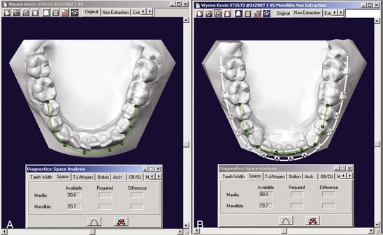
FIGURE 14-1 Digitized dental casts (here in the Ortho-CAD system) can be used quite effectively to calculate the amount of space needed to align the teeth, show the probable outcome of alignment, and calculate the arch length needed. A, Pretreatment occlusal view of the lower arch, with a line showing the amount of space required for alignment. B, Virtual appliance in place.
In this and the subsequent chapters, it is expected that the appropriate goals for an individual patient have been clearly stated, and the discussion here concerns only the treatment techniques necessary to achieve those goals. Orthodontic treatment without specific goals can be an excellent illustration of the old adage, “If you don’t know where you’re going, it doesn’t matter which road you take.”
Alignment
Principles in the Choice of Alignment Arches
In nearly every patient with malaligned teeth, the root apices are closer to the normal position than the crowns, because malalignment almost always develops as the eruption paths of teeth are deflected. Putting it another way, a tooth bud occasionally develops in the wrong place, but the root apices are likely to be reasonably close to their correct positions even though the crowns have been displaced as the teeth erupted. The major exceptions to this guideline are the displacement of all tissues in an area, most often seen as a result of cleft palate surgery, and the severe tipping from lip pressure that displaces maxillary central incisors in Class II, division 2 malocclusion. To bring teeth into alignment, a combination of labiolingual and mesiodistal tipping guided by an archwire is needed, but root movement usually is not. Several important consequences for orthodontic mechanotherapy follow from this:
1. Initial archwires for alignment should provide light, continuous force of approximately 50 gm to produce the most efficient tipping tooth movement. Heavy force, in contrast, is to be avoided.
2. The archwires should be able to move freely within the brackets. For mesiodistal sliding along an archwire, at least 2 mil clearance between the archwire and the bracket is needed, 4 mil clearance is desirable, and more than that provides no advantage. This means that the largest initial archwire that should be used with an 18-slot edgewise bracket is 16 mil, and 14 mil would be more satisfactory. With the 22-slot bracket, a 16 or 18 mil archwire would be satisfactory if they delivered the correct force. Whatever the archwire, it should be held loosely in the bracket; however, as we have pointed out in Chapter 9, friction is not the major component of resistance to sliding, and the claim that more rapid alignment is a major advantage of self-ligating brackets has been shown to be incorrect.
3. Rectangular archwires, particularly those with a tight fit within the bracket slot so that the position of the root apex could be affected, normally should be avoided. The principle is that it is better to tip crowns to position during initial alignment rather than displacing the root apices; the corollary is that although a highly resilient rectangular archwire, such as 17 × 25 superelastic NiTi (A-NiTi), could be used in the alignment stage, this is not advantageous because the rectangular archwire can create unnecessary and undesirable root movement during alignment (Figure 14-2). Superelastic NiTi wires have such low torsional strength that for all practical purposes they cannot torque roots,2 so this complication is uncommon, but mesiodistal movement of the root apices can and does occur, and this tends to slow the tipping movements needed for alignment. Round wires for alignment are preferred (Figure 14-3). There is no reason to pay extra for a high-performance rectangular wire for initial alignment, when alignment with it predictably will be slower and possibly more damaging to the roots than with a smaller round wire.
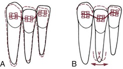
FIGURE 14-2 A tightly fitting resilient rectangular archwire for initial alignment is almost always undesirable because not only is resistance to sliding likely to be problematic, but also the wire produces back-and-forth movement of the root apices as the teeth move into alignment. This occurs because the moments generated by the archwire change as the geometry of the system changes with alterations in tooth position. A, Diagrammatic representation of the alignment of a malposed lateral incisor with a round wire and clearance in the bracket slot. With minimal moments created within the bracket slot, there is little displacement of the root apex. B, With a rectangular archwire that has enough torsional stiffness to create root movement, back-and-forth movement of the apex occurs before the tooth ends up in essentially the same place as with a round wire. This has two disadvantages: it increases the possibility of root resorption, and it slows the alignment process.
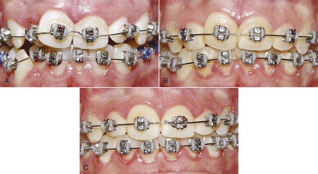
FIGURE 14-3 The sequence of alignment with a fixed appliance, in this case using Tip-Edge brackets (see Chapter 10). A, The initial superelastic round wire (16 mil A-NiTi), which was preformed with a midline bend to prevent archwire travel. B, 16 steel for final alignment 2 months later. C, Alignment completed 3 months later.
4. The springier the alignment archwire, the more important it is for the crowding to be at least reasonably symmetric. Otherwise, there is a danger that arch form will be lost as asymmetrically irregular teeth are brought into alignment. If only one tooth is crowded out of line or if an impacted tooth has to be brought into alignment—a more severe version of the same thing—a rigid wire is needed so that arch form is maintained except where springiness is required, and an auxiliary wire should be used to reach the malaligned tooth. This important point is discussed in some detail below.
Properties of Alignment Archwires
The wires for initial alignment require a combination of excellent strength, excellent springiness, and a long range of action. Ideally, there would be an almost flat load-deflection curve, with the wire delivering about 50 gm (the optimum force for tipping) at almost any degree of deflection. The variables in selecting appropriate archwires for alignment are the archwire material, its size (diameter or cross-section), and the distance between attachments (interbracket span; see Chapter 9).
At this point, superelastic A-NiTi wires are so much more effective and efficient than any alternative that there is no reason to discuss any other archwire material for alignment. The key to their success is their ability to deliver light force over a long range. The use of multiple strands of steel wire was a way to improve the performance of steel wires in initial alignment; now multiple strands of A-NiTi are being used to deliver lighter force with an archwire that is stronger and has better resistance to fracture (see Figure 14-3). Since the manufacturer’s preparation of the material determines the clinical performance, wire size is a concern primarily with respect to clearance in the bracket slot and fracture resistance. Although a 16 mil A-NiTi wire can be stiffer and deliver more force than a differently prepared 18 mil wire, that would not be possible across the total range of wire sizes, so wire size is a consideration, just less important in selecting an A-NiTi wire.
It is possible now to obtain superelastic wires that are almost totally passive when cold but deliver the desired force when at mouth temperature. Placing a chilled wire is much easier than placing a springy one, so chilling a segment of the wire to make it temporarily passive can be a significant advantage under some circumstances. On the other hand, once mouth temperature has been reached, there is no reason to expect such a thermally sensitive wire to perform better than one without this feature.
As we have discussed in Chapter 9, it is logical to use narrow (single) brackets with 18-slot edgewise and wider (twin) brackets with 22-slot. Prior to almost routine use of superelastic wires, bracket slot size and interbracket span were such strong influences on archwire choice that different initial wires often were used with the 18- and 22-slot appliances. This is no longer the case. But with superelastic wires, it is necessary to pay more attention to maintaining arch form during alignment to the point that alignment when crowding is reasonably symmetric now must be viewed differently from alignment in highly asymmetric situations.
Alignment of Symmetric Crowding
The flat load-deflection curve of superelastic NiTi (Figure 14-4) makes it ideal for initial alignment when the degree of crowding is similar on the two sides of the arch. The superelastic wire provides remarkable range over which a tooth can be moved without generating excessive force. Under most circumstances, initial alignment can be accomplished simply by tying 14 or 16 mil A-NiTi that delivers about 50 gm into the brackets of all the teeth (see Figure 14-3). It must be kept in mind, however, that alignment requires opening space for teeth that are crowded out of the arch. There are two ways to do this: use a crimped stop on the wire just in front of the molar tube so that the archwire is “proud” (slightly advanced from the crowded incisors) or use coil springs to open space (Figure 14-5). If this is done, the springs must deliver only light force to prevent distortion of arch form. The size of the superelastic wire is not a critical variable if it delivers the desired ≈50 gm force, except that 18 mil wires should not be used in the 18-slot appliance.
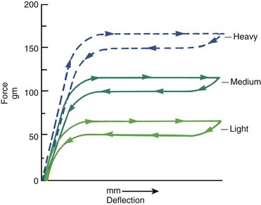
FIGURE 14-4 Idealized force-deflection curves for 16 mil A-NiTi wires (Sentinol, GAC) prepared by the manufacturer to have different force delivery characteristics. For superelastic wires, the manufacturer’s preparation, not the wire size, is the major factor in determining force delivery. Note that the light version of this wire delivers the desired 50 gm for initial alignment.
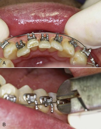
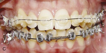
FIGURE 14-5 When additional arch length is needed, advanced stops in the flexible initial archwire are useful. A, A-NiTi archwire advanced relative to crowded incisors. Stops on the archwire are needed to hold it in a slightly advanced position. B, Crimped split tube segments, like those used to prevent travel, serve well as advanced stops for superelastic initial wires. C, An alternative for gaining arch length is the use of compressed coil springs to open space for crowded-out incisors. The effect of the two methods is quite similar—incisor proclination occurs about equally.
When superelastic NiTi was first introduced, the major objection to it was that it is expensive. If a large range is not necessary, a triple-strand 17.5 mil multistrand steel wire (3 × 8 mil) offers good properties at a fraction of the cost. In theory, this size would be too large for effective use in 18-slot brackets. Clinical research has shown, however, that in both the 18 and 22 appliance, if these wires are recontoured monthly and retied with elastomeric ligatures, the time to alignment is equivalent to A-NiTi. Force levels certainly are more variable and patient discomfort probably is greater than with superelastic wires, but it is difficult to demonstrate this makes a difference clinically.
The reason for this surprisingly good clinical performance by the multistrand steel wire probably is that flexible archwires allow the teeth to move relative to each other during chewing, as alveolar bone bends under masticatory loads (see Chapter 8). This releases binding and allows the bracket to slide along the archwire to the next point at which binding occurs. But the lower cost of the steel archwire is quickly overbalanced by the additional clinical time necessary to retie it, especially if it must be taken out, adjusted to remove any areas of permanent distortion, and then re-ligated.
Laboratory data and clinical experience suggest that similar performance to the multistrand steel wire could be obtained with elastic NiTi [M-NiTi], a variety of more elaborate multistrand wires (coaxial wires, for instance, that have several smaller wires wound over a larger core wire), or with loops in small diameter steel wires. Both M-NiTi and coaxial multistrand wires are expensive, and the time to bend loops in 14 or 16 steel wires also is expensive. These wires, though they were the standard of treatment for initial alignment not long ago, have little or no place in current therapy.
As one might expect, the extreme springiness of superelastic wires is not a totally unmixed blessing. When these wires are tied into a malaligned dental arch, they have a tendency to “travel” around the arch as the patient chews, especially if function is mostly on one side. Then the wire sticks out the back of the molar tube on one side and may come out of the tube on the other side. Occasionally, this can be extreme enough to produce the kind of situation Mark Twain called “marvelous and dismaying” (Figure 14-6, A). Archwire travel can be prevented by crimping a stop tightly onto the archwire between any two brackets that are reasonably close together (Figure 14-6, B) or by cinching the end of the wire with a special plier that will bend the NiTi wire. A stop of this type should be used routinely on initial superelastic wires.
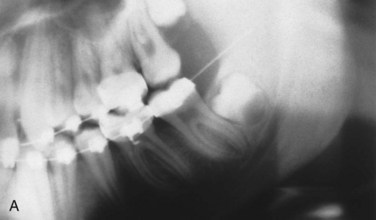
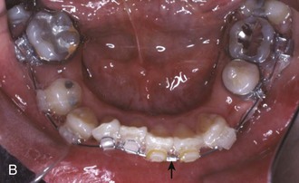
FIGURE 14-6 One problem with superelastic wires for initial alignment is their tendency to “travel” so that the wire slips around to one side, protruding distally from the molar tube on one side and slipping out of the tube on the other. A, This panoramic radiograph shows archwire travel to the point that on one side it penetrated into the ramus, almost to the depth of an inferior alveolar block injection (interestingly, the patient reported only mild discomfort). B, The most effective way to prevent travel is to tightly crimp a split tube segment onto the wire between two adjacent brackets. The location of the crimped stop, here between the left central and lateral incisors, is not critical. Some preformed A-NiTi wires now have a dimple in the midline to prevent the archwire from sliding excessively.
Alignment in Premolar Extraction Situations
In patients with severe crowding of anterior teeth, it is necessary to retract the canines into premolar extraction sites to gain enough space to align the incisors. In extremely severe crowding, it is better to retract the canines independently before placing attachments on the incisors. If maximum anchorage is needed, this can be done most efficiently now with skeletal anchorage from bone screws in the alveolus (Figure 14-7).
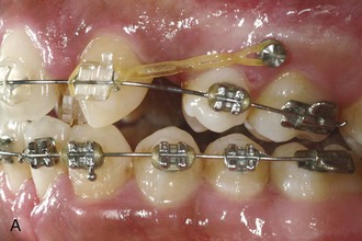
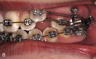
FIGURE 14-7 When anchorage is critical for retraction of canines to allow alignment of incisors, bone screws placed in the alveolar process between the molar and premolar roots are the most effective way to obtain the necessary space. A, The anchorage can be direct, with an elastomeric chain or NiTi spring from the bone screw providing the force to retract the canines or (B) indirect, with an attachment from the bone screw to the first molar to keep those teeth from moving forward when an attachment from the posterior teeth is used to retract the canine.
In less extreme but still severe crowding, it is possible to simultaneously tip the canines distally and align the incisors. This can be obtained with an A-NiTi archwire coupled with A-NiTi coil springs from the first molars to tip the canines distally (Figure 14-8). The archwire must be one that was preformed by the manufacturer to have an exaggerated reverse curve of Spee, in order to limit forward tipping of the molars. This provides a way to pit distal tipping of the canines against forward bodily movement of the molars, although the moment across the molar tube will not be enough to totally prevent mesial tipping.
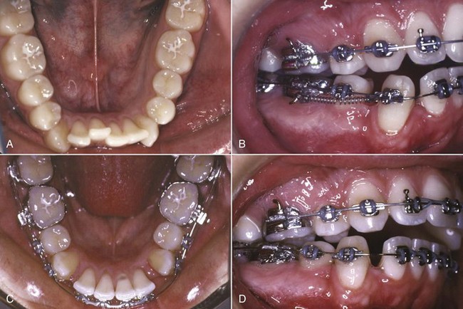
FIGURE 14-8 Alignment of severely crowded lower incisors with the superelastic equivalent of the original “drag loop.” A, Occlusal view prior to treatment. B, Canine retraction with superelastic coil springs that provide 75 gm of force, and alignment of incisors with a superelastic NiTi wire that incorporates an accentuated reverse curve of Spee and delivers 50 gm. C and D, Completion of canine retraction and incisor alignment after 5 months of treatment.
Alignment in Nonextraction Situations
Alignment in nonextraction cases requires increasing arch length, moving the incisors further from the molars. In this circumstance, just tying a superelastic wire into the bracket slots is ineffective. Two objects cannot occupy the same space at the same time, so alignment cannot occur until space to allow it is created.
The most straightforward way to accomplish this is to crimp a stop on the wire at the molar tube, so that it holds the wire just in front of the incisors (see Figure 14-3). At subsequent appointments, if more arch length is needed, an additional stop or stops can be quickly slipped into position, without removing the wire. When a broad arch form is used, transverse expansion across the premolars will occur. Even so, this type of arch expansion has the potential to carry the incisors facially, and so it is not indicated in the presence of severe crowding unless incisor protrusion is desired.
An alternative is to bypass the brackets on teeth that are crowded lingually, and place coil springs over the A-NiTi archwire to generate space (see Figure 14-3, D). When this is done, the archwire must be free to slide forward through the molar tubes and must be slightly long initially so that it will not come completely out of the tubes. The coil spring force must be very light to prevent distortion of arch form, but it is a misconception that the force is so light the incisors will not be proclined. They will be, just as they are when advanced stops are used. Importantly, this technique must be modified as described below if the crowding is significantly asymmetric.
Asymmetric Crowding
When all or nearly all the crowding is in one place, what is needed is an archwire that is rigid where the teeth are already aligned and quite springy where they are not. Nothing in this world is an unmixed blessing, and the extreme springiness of a superelastic wire means that if it is tied into an asymmetrically malaligned arch, teeth distant to the site of malalignment will be moved. An impacted canine is the prime example of asymmetric malalignment. This situation is discussed more specifically below, but it is easy to understand that if a continuous superelastic wire were tied to the impacted canine and to the lateral incisor and premolar adjacent to it, the incisor and premolar would be tipped into the canine space as it was pulled toward proper position. If one lateral incisor is blocked out of the arch and must be brought into position, the same guideline applies: a superelastic wire to bring it into alignment would move the adjacent canine and central incisor much more than would be desired.
It is easy to add a small diameter superelastic wire as an auxiliary spring, so that a stiff main arch (16 or 18 steel) can be tied into all the teeth except the displaced one (or two—the same system works with small segments of two teeth). A segment of superelastic NiTi can be laid in the brackets on top of the main archwire, or tied below the brackets of the anchor teeth, and tied to the bracket on the displaced tooth (Figure 14-9). Some modern brackets even provide an accessory horizontal tube for this purpose (see Figure 10-35). With this arrangement, the correct light force to bring the displaced tooth into alignment is provided by the NiTi wire, and the reciprocal force is distributed over all the rest of the teeth. The result is efficient movement of the displaced tooth, with excellent preservation of arch form. When the displaced tooth is nearly into proper position, the steel base arch can be discarded and the NiTi auxiliary tied into the bracket slots.
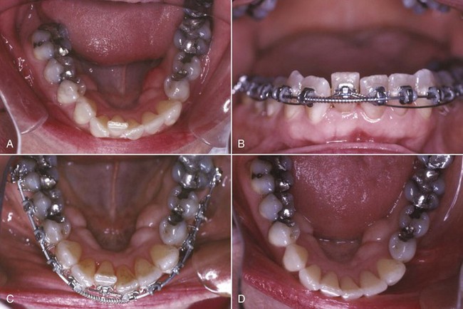
FIGURE 14-9 Use of an auxiliary superelastic wire for incisor alignment in a patient with asymmetric crowding. A, Crowding expressed largely as displacement of one lower lateral incisor in an adult with periodontal bone loss for whom light force was particularly important. B and C, After space was opened for the right lateral incisor, a superelastic wire segment tied beneath the brackets was used to bring the lateral incisor into position, while arch form was maintained by a heavier archwire in the bracket slots. D, Alignment completed. This approach allows use of optimal force on the tooth to be moved and distributes the reaction force over the rest of the teeth in the arch.
Note that there are two advantages of using the superelastic wire as an auxiliary to a rigid steel wire: control of the tendency to distort arch form and light force against the tooth to be moved. Although auxiliaries of this type are recommended routinely in modern orthodontics, it would be particularly important to use this method for adult patients with loss of alveolar bone and a reduced periodontal ligament area.
Crossbite Correction
It is important to correct posterior crossbites and mild anterior crossbites (one or two displaced teeth) in the first stage of treatment. Severe anterior crossbites (all the teeth), in contrast, are usually not corrected until the second stage of conventional treatment or might remain pending surgical correction. For both posterior and anterior crossbites, it is obviously important to make the appropriate distinctions between skeletal and dental problems and to quantitate the severity of the problem. The appropriate diagnostic steps are discussed in Chapters 6 and 7. The assumption here is that appropriate treatment has been selected, and the discussion is solely about implementing a treatment plan based on differential diagnosis.
Individual Teeth Displaced Into Anterior Crossbite
Anterior crossbite of one or two teeth almost always is an expression of severe crowding (Figure 14-10). This is most likely to occur when maxillary lateral incisors that are somewhat lingually positioned to begin with are forced even more lingually by lack of space. Correction of the crossbite requires first opening enough space, then bringing the displaced tooth or teeth across the occlusion into proper position.
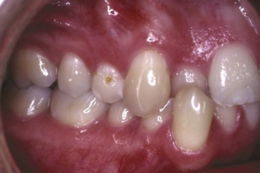
FIGURE 14-10 Correction of a dental anterior crossbite, as in this young adult, requires opening enough space for the lingually displaced maxillary incisor before attempting to move it facially into arch form. At that point, a biteplate to obtain vertical clearance often is required.
Occlusal interferences can make this difficult. The patient may tend to bite brackets off the displaced teeth, and as the teeth are moved “through the bite,” occlusal force pushes them one way while the orthodontic appliance pulls them the other. It may be necessary to use a biteplate temporarily to separate the posterior teeth and create the vertical space needed to allow the teeth to move. The older the patient, the more likely it is that a biteplate will be needed. During rapid growth in early adolescence, often incisors that were locked in anterior crossbite can be corrected without a biteplate. After that, one probably will be required.
Transverse Maxillary Expansion by Opening the Midpalatal Suture
It is relatively easy to widen the maxilla by opening the midpalatal suture before and during adolescence, but this becomes progressively more difficult as patients become older because of the increased interdigitation of the sutures (see Figure 8-30).
Patients who are candidates for opening the midpalatal suture may have such severe crowding that even with this arch expansion, premolar extraction will be required. In these patients, however, separation of the suture should be the first step in treatment, before either extraction or alignment. The first premolar teeth are useful as anchorage for the lateral expansion and can serve for that purpose even if they are to be extracted later, and the additional space provided by the lateral expansion facilitates alignment.
Sometimes, transverse maxillary expansion can provide enough additional space to make extraction unnecessary, but rarely is it wise to use sutural expansion as a means of dealing with crowding in an individual who already has normal maxillary width. Opening the midpalatal suture should be used primarily as a means of correcting a skeletal crossbite by making a narrow maxilla normal, not a normal maxilla abnormally wide.
The techniques for expansion across the midpalatal suture in the late mixed or early permanent dentition are presented in some detail in Chapter 13. Slow expansion, with one turn ( mm) of the screw every other day, is recommended over rapid expansion in these younger patients because it is more physiologic and equally effective. Up to about age 15 (skeletal age), it almost always is possible to open the suture (Figure 14-11). Beyond that level of maturity, it is increasingly difficult to create the microfracturing necessary to open the suture. For that reason, more rapid activation of the expansion screw initially is recommended for more mature patients. Two turns initially and two turns per day until the suture opens (often the patient hears and feels it pop apart) is more likely to generate the desired sutural expansion. For these patients, slow expansion is likely to produce only dental expansion. If the suture does not open within 2 to 3 days with rapid activation of the screw, surgically assisted expansion (see Chapter 19) becomes the only possibility.
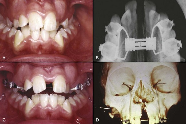
FIGURE 14-11 Palatal expansion in adolescents requires a rigid framework because of the heavy forces (2 to 4 pounds with slow expansion, 10 to 20 pounds with rapid expansion) that will be encountered. Although the various expansion appliances look quite different (see Chapter 13), they produce similar results. A, Severe maxillary constriction leading to bilateral crossbite. B and C, Progress with rapid expansion in this patient. Note the development of a space between the central incisors as the suture expands more anteriorly than posteriorly. D, Expansion on a skull showing how the palate opens as if on a hinge at the base of the nose.
In the mixed dentition, a bonded expander often is easier to place than a banded one and may be selected for that reason. For patients in the permanent dentition, the primary indication for a bonded expander is for expansion in a patient who already has excessive anterior face height.3 A bonded expander of necessity covers the occlusal surface of the posterior teeth, creating a biteplate effect, and this reduces the potential for downward-backward rotation of the mandible during expansion (Figure 14-12). A banded expander almost always creates some mandibular rotation because occlusal interferences are created as the teeth are moved, which would be ideal for a short-face patient. For patients with normal face height, either type of expander can be used without great concern for mandibular rotation.
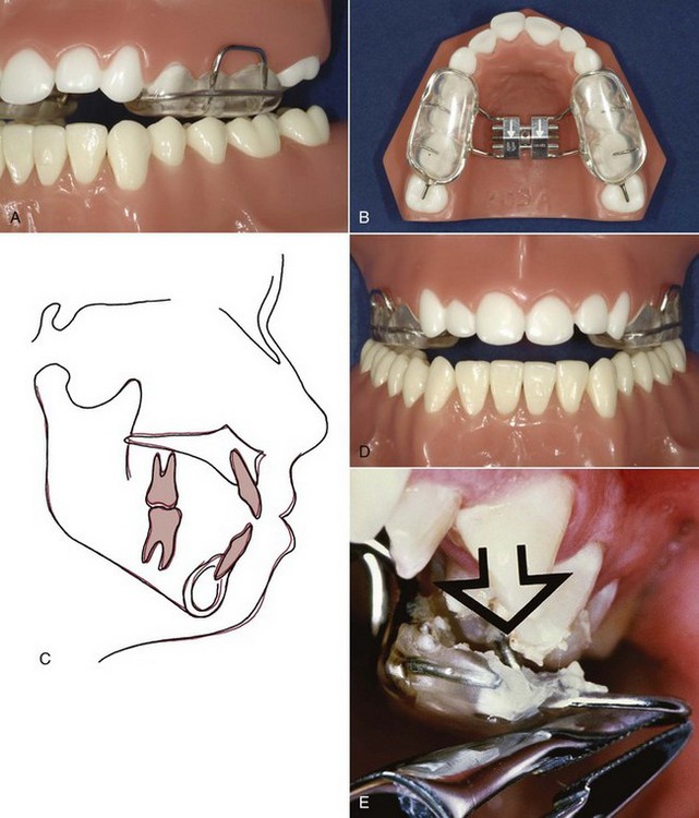
FIGURE 14-12 A and B, A bonded expander, shown here on a typodont, has two potential advantages over a banded type: (1) occlusal force against the acrylic over the posterior teeth reduces the amount of extrusion and downward-backward rotation of the mandible that typically accompanies maxillary expansion, which is important in patients with a long-face tendency, and (2) the bonded type is easier to use in children in the mixed dentition. C, Cephalometric superimposition before and after expansion, showing the small amount of mandibular rotation when expansion was done with a device of this type. D and E, Removal of a bonded appliance of this type is facilitated by loops extending from the appliance that can be gripped and torqued.
Correction of Dental Posterior Crossbites
Three approaches to correction of less severe dental crossbites are feasible: a heavy labial expansion arch, as shown in Figure 14-13; an expansion lingual arch; or cross-elastics. Removable appliances, although theoretically possible, are not compatible with comprehensive treatment and should be reserved for the mixed dentition or adjunctive treatment.
FIGURE 14-13 A heavy labial archwire (usually 36 or 40 mil steel) placed in the headgear tubes on first molars can be used for a small amount of expansion and to maintain arch width after palatal suture opening while the teeth are being aligned. This is more compatible with fixed appliance treatment than a removable retainer and does not depend on patient cooperation. (From Proffit WR, White RP, Sarver DM. Contemporary Treatment of Dentofacial Deformity. St. Louis: Mosby; 2003.)
The inner bow of a facebow is also, of course, a heavy labial arch, and expansion of this inner bow is a convenient way to expand the upper molars in a patient who is wearing headgear. This expansion is nearly always needed for patients with a Class II molar relationship, whose upper arch usually is too narrow to accommodate the mandibular arch when it comes forward into the correct relationship because the upper molars are tipped lingually. The inner bow is simply adjusted at each appointment to be sure that it is slightly wider than the headgear tubes and must be compressed by the patient when inserting the facebow. If the distal force of a headgear is not desired, a heavy labial auxiliary can provide the expansion effect alone. The effect of the round wire in the headgear tubes, however, is to tip the crowns outward, and so this method should be reserved for patients whose molars are tipped lingually.
A transpalatal lingual arch for expansion must have some springiness and range of action. As a general principle, the more flexible a lingual arch is, the better it is for tooth movement but the less it adds to anchorage stability. This can be an important consideration in adolescent and adult patients. If anchorage is of no concern, a highly flexible lingual arch, like the quad-helix design discussed in Chapter 12, is an excellent choice for correction of a dental crossbite. When the lingual arch is needed for both expansion and anchorage, however, the choices are 36 mil steel wire with an adjustment loop, or the newer system that allows the use of 32 × 32 TMA or steel wire (Figure 14-14).
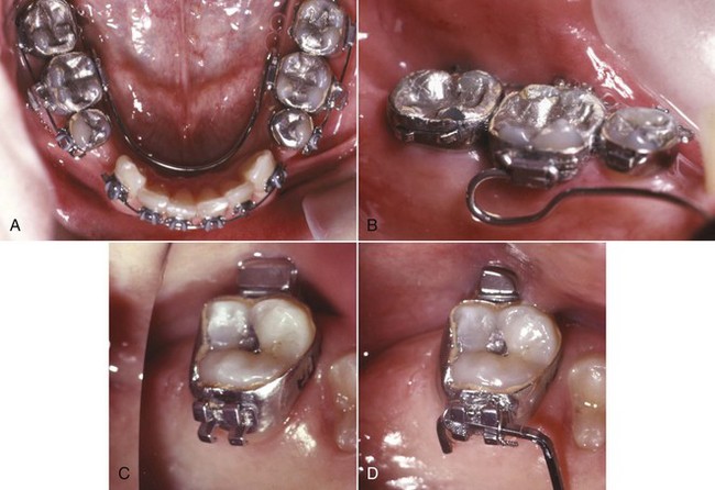
FIGURE 14-14 A and B, Mandibular stabilizing lingual arch. It is easier to insert a heavy lingual arch of this type from the distal of a horizontal tube on the first molar bands. Note that the lingual arch is contoured away from the incisors, so that it does not interfere with aligning and retracting them. C and D, A maxillary lingual arch can be active, typically to rotate the maxillary molars, or passive for stabilization. An active lingual arch can be placed in a horizontal tube or ligated into a special bracket on the molars, as shown here. Ligation into a bracket makes it easier to remove and adjust the lingual arch, but over time, gingival overgrowth can make re-ligation difficult.
The third possibility for dental expansion is the use of cross-elastics, typically running from the lingual of the upper molar to the buccal of the lower molar (Figure 14-15). These elastics are effective, but their strong extrusive component must be kept in mind. As a general rule, adolescent patients can tolerate a short period of cross-elastic wear to correct a simple crossbite because any extrusion is compensated by vertical growth of the ramus, but cross-elastics should be used with great caution, if at all, in adults. As any posterior crossbite is corrected, there is a tendency to rotate the mandible downward and backward, even if cross-elastics are avoided. The elastics accentuate this tendency.
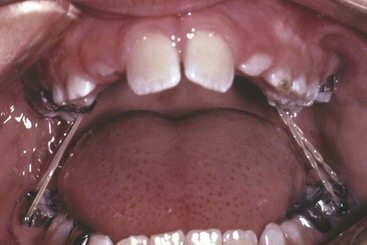
FIGURE 14-15 Cross-elastics from the lingual of the upper molars to the buccal of the lower molars. Cross-elastics are an effective way of correcting transverse dental relationships, but they also extrude teeth, and this must be kept in mind.
If teeth are tightly locked into a posterior crossbite relationship, a biteplate to separate them vertically can make the correction easier and faster. In children and young adolescents, this is rarely needed. Use of a biteplate during transverse expansion indicates that elongation of the posterior teeth and downward-backward rotation of the mandible is an acceptable outcome.
Impacted or Unerupted Teeth
Bringing an impacted or unerupted tooth into the arch creates a set of special problems during alignment. The most frequent impaction is a maxillary canine or canines, but it is occasionally necessary to bring other unerupted teeth into the arch, and the same techniques apply for incisors, canines, and premolars. Impacted lower second molars pose a different problem and are discussed separately.
The problems in dealing with an unerupted tooth fall into three categories: (1) surgical exposure, (2) attachment to the tooth, and (3) orthodontic mechanics to bring the tooth into the arch.
Surgical Exposure
Before surgery to expose an unerupted tooth, it is obviously important to know with some precision where it is. This now is an indication for cone-beam computed tomography (CBCT), using a unit with a small field of view (FOV) unless there is an indication for a large FOV (primarily, jaw asymmetry).4,5 The older radiographic methods, a combination of the panoramic and an occlusal film (the vertical parallax method) or multiple periapical radiographs (the lateral cone shift method), require similar radiation exposure and provide much less information (see Chapter 7). With a CBCT image, often it is apparent that before an impacted canine can be pulled downward toward its position in the dental arch, it will be necessary to move it away from the roots of the central or lateral incisor—information that changes treatment plans and was not available with previous radiographic methods.
It is important for a tooth to erupt through the attached gingiva, not through alveolar mucosa, and this must be considered when exposure of an unerupted tooth is planned. If the canine is labially positioned and probing shows that the crown is not covered with attached tissue, the crown can be exposed with a laser (Figure 14-16). If the unerupted tooth is more apically positioned in the mandibular arch or on the labial side of the maxillary alveolar process, a flap should be reflected from the crest of the alveolus and sutured so that attached gingiva has been transferred to the region where the crown is exposed (see Figure 11-33). If this is not done and the tooth is brought through alveolar mucosa, it is quite likely that tissue will strip away from the crown, leaving an unsightly and periodontally compromised gingival margin.6 For a very high canine that is positioned labially, a tunnel method is an alternative to raising a flap. If the unerupted tooth is on the palatal side, similar problems with the heavy palatal mucosa are unlikely, and an open exposure can be used.
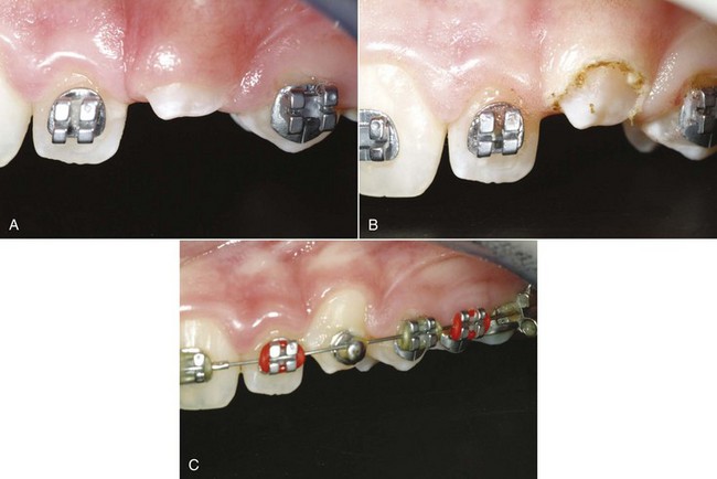
FIGURE 14-16 If an impacted canine is on the labial, removing tissue to expose the crown for bonding an attachment can be done conveniently with a diode laser. A, The permanent canine was slow to erupt. Probing showed that exposure of 4 mm of the crown could be done without violating the biologic width of the attachment apparatus. B, Immediately after crown exposure with a laser. C, The tooth brought to the occlusal level with a superelastic wire, ready for placement of a bracket in ideal position.
Occasionally, a tooth will obligingly erupt into its correct position after obstacles to eruption have been removed by surgical exposure, and delaying orthodontic traction to palatally impacted canines with incomplete roots is now recommended, but favorable spontaneous movement rarely occurs after root formation is complete. At that stage, even a tooth that is aimed in the right direction usually requires orthodontic force to bring it into position.
Method of Attachment
The best contemporary approach is to directly bond an attachment of some type to an exposed area of the crown. In many instances, a button or hook is better than a standard bracket because it is smaller. Then, if the tooth will be covered when the flap is replaced, a piece of fine gold chain is tied to the attachment, and before the flap is repositioned and sutured into place, the chain is positioned so that it extends into the mouth. The chain is much easier to tie to than a wire ligature. Before the availability of direct bonding, a pin was sometimes placed in a hole prepared in the crown of an unerupted tooth, and in special circumstances, this remains a possible alternative.
The least desirable way to obtain attachment is for the surgeon to place a wire ligature around the crown of the impacted tooth. This inevitably results in loss of periodontal attachment because bone that is destroyed when the wire is passed around the tooth does not regenerate when it is removed and increases the chance of ankylosis. Occasionally, no alternative is practical, but wire ligatures should be avoided whenever possible.
Mechanical Approaches for Aligning Unerupted Teeth
Orthodontic traction to move an unerupted tooth away from other permanent tooth roots, if necessary, and then toward the line of the arch should begin as soon as possible after surgery. Ideally, a fixed orthodontic appliance should already be in place before the unerupted tooth is exposed, so that orthodontic force can be applied immediately. If this is not practical, active orthodontic movement should begin no later than 2 or 3 weeks postsurgically.
This means that for a labially impacted canine, orthodontic treatment to open space for the unerupted tooth and allow stabilization of the rest of the dental arch must begin well before the surgical exposure. In this instance, the goals of presurgical orthodontic treatment are to create enough space if it does not exist, as often is the case; and to align the other teeth so that a heavy stabilizing archwire (at least 18 steel, preferably a rectangular steel wire) can be in position at the time of surgery. This allows postsurgical orthodontic treatment to start immediately. For a palatally impacted canine, open exposure often leads to downward drift, so immediate active treatment can be deferred for many of these patients.
As we have noted previously, an unerupted tooth is an extreme example of an asymmetric alignment problem, with one tooth far from the line of occlusion. An auxiliary NiTi wire, overlaid on the stabilizing arch in the same way as recommended for other asymmetric alignment situations (Figure 14-17), is the most efficient way to bring an impacted tooth into position. The numerous alternatives include a special alignment spring, either soldered to a heavy base archwire or bent into a light archwire, or a cantilever spring from the auxiliary tube on the first molar.
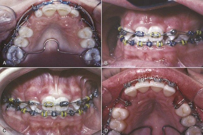
FIGURE 14-17 A, For this patient with palatally positioned bilateral impacted maxillary canines, a soldered lingual arch has been placed for better anchorage control; a heavy labial archwire is in place after space for the canines has been opened; and an auxiliary A-NiTi wire is tied to attachments (preferably, a segment of gold chain) that were bonded to the canines at the time they were exposed. B, Progress in the same patient, with the A-NiTi auxiliary now placed over a button that was bonded on the facial surface of the canine after it was brought down enough to allow this. C, When the tooth has elongated enough, the button is replaced with a standard canine bracket and alignment is complete. D, A vertical spring bent into a 14 mil steel archwire is an alternative approach to bring down an impacted canine. The spring is a loop of wire that faces downward before activation and is rotated 90 degrees for attachment to the impacted tooth or teeth. This method is effective but less efficient than using a superelastic auxiliary wire.
Another possibility, magnetic force to initiate movement of an unerupted tooth, is especially attractive for a patient with other missing teeth in the maxillary arch because no mechanical connection is required. The technique involves bonding a small magnet to the unerupted maxillary tooth and placing a larger magnet in attraction within a palate-covering removable appliance (Figure 14-18). Unfortunately, success depends entirely on the patient’s cooperation in wearing the removable appliance with the intraoral magnet all the time.
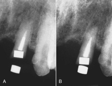
FIGURE 14-18 A and B, Use of magnets in attraction, one placed in the root of a fractured premolar and the other in a removable plate, to elongate a fractured tooth so that its crown can be restored. (From Sandler JP. Am J Orthod Dentofac Orthop 100:489-493, 1991.)
Ankylosis of an unerupted tooth is always a potential problem. If an area of fusion to the adjacent bone develops, orthodontic movement of the unerupted tooth becomes impossible, and displacement of the anchor teeth will occur. Occasionally, an unerupted tooth will start to move and then will become ankylosed, apparently held by only a small area of fusion. It can sometimes be freed to continue movement by anesthetizing the area and lightly luxating the tooth, breaking the area of ankylosis. If this procedure is done, it is critically important to apply orthodontic force immediately after the luxation, since it is only a matter of time until the tooth re-ankyloses. Nevertheless, this approach can sometimes allow a tooth to be brought into the arch that otherwise would have been impossible to move.
Unerupted/Impacted Lower Second Molars
Unlike impaction of most other teeth, which is an obvious problem from the beginning of treatment, impaction of lower second molars usually develops during orthodontic treatment. This occurs when the mesial marginal ridge of the second molar catches against the distal surface of the first molar or on the edge of a first molar band, so that the second molar progressively tips mesially instead of erupting. Moving the first molar posteriorly during the mixed dentition increases the chance that the second molar will become impacted. This possibility must be taken into account when procedures to increase mandibular arch length are employed. Many clinicians now delay or avoid banding of lower first molars because of this risk.
Correction of an impacted second molar requires tipping the tooth posteriorly and uprighting it (Figure 14-19). In most cases, if the mesial marginal ridge can be unlocked, the tooth will erupt on its own. When the second molar is not severely tipped, the simplest solution is to place a separator between the two teeth. For more severe problems, an attachment must be bonded to the second molar. An auxiliary spring (Figure 14-20) often is useful to bring both upper and lower second molars into alignment when they erupt late in orthodontic treatment. The easiest way to do this is to use a segment of NiTi wire from the auxiliary tube on the first molar to the tube on the second molar. A rectangular wire, usually 16 × 22 M-NiTi, is preferred. This provides a light force to align the second molars while a heavier and more rigid wire remains in place anteriorly, which is much better than going back to a light round wire for the entire arch just to align the second molars.
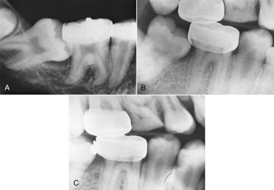
FIGURE 14-19 A, Radiographic view of an impacted mandibular second molar in a 16-year-old patient. Uprighting the tooth from this position requires surgical exposure of a portion of the facial surface of the crown and bonding an attachment (if possible, a tube) so that a spring can be used to tip it distally and bring it into the arch. B, For a second molar that is caught on the edge of a first molar band, a simpler approach is uprighting achieved with a 20 mil brass wire tightened around the contact. Usually it is necessary to anesthetize the area to place a separator of this type. C, Uprighting and distal movement obtained with the brass wire separator (same patient as B). A spring clip (one type is sold as the Arkansas de-impaction spring) can be used in the same way, but both brass wire and spring clips are effective only for minimal molar uprighting.
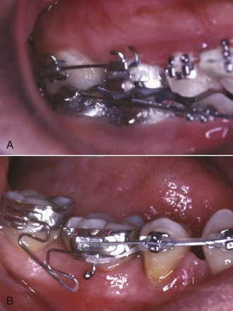
FIGURE 14-20 When a second molar is banded or bonded relatively late in treatment, often it is desirable to align it with a flexible wire while retaining a heavier archwire in the remainder of the arch. A, Repositioning a maxillary second molar, using a straight segment of rectangular A-NiTi wire that fits into the auxiliary tube on the first molar and the tube for the main archwire on the second molar. B, Repositioning a mandibular second molar, using a segment of steel wire with a loop that extends from the auxiliary tube on the first molar. In both arches, after the repositioning, a continuous archwire can extend to the second molar.
Another possibility in adolescents is surgical uprighting of the impacted second molar, taking advantage of the space that is created when the third molar is extracted. In carefully selected cases, this can work quite nicely. Vitality of the second molar is retained because it essentially is rotated around the root apex, and the defect on the mesial of the uprighted tooth fills in with bone in the same way that it does when orthodontic uprighting is done (Figure 14-21).7 The outcome is best when some vertical jaw growth remains so that the uprighted tooth does not remain elongated relative to the first molar.
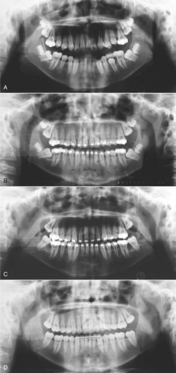
FIGURE 14-21 Surgical uprighting of impacted mandibular second molars sometimes is the easiest way to deal with severe impactions. A, Age 12, prior to loss of the second primary molars, with the permanent second molars tipped mesially against the first molars. Teeth in this position often upright spontaneously when the first molars drift mesially after the primary molars are lost. B, Age 14, severe impaction one year after the beginning of orthodontic treatment. C, Age 14, after surgical uprighting of the second molars, which are rotated around their root apex into the space created by third molar extraction. Loss of pulp vitality usually does not occur when this is done. D, Age 16, after completion of orthodontic treatment. Note the excellent fill-in of bone between the first and second molars.
Diastema Closure
A maxillary midline diastema is often complicated by the insertion of the labial frenum into a notch in the alveolar bone, so that a band of heavy fibrous tissue lies between the central incisors. When this is the case, a stable correction of the diastema almost always requires surgery to remove the interdental fibrous tissue and reposition the frenum. The frenectomy must be carried out in a way that will produce a good esthetic result and must be properly coordinated with orthodontic treatment.
It is an error to surgically remove the frenum at an early age and then delay orthodontic treatment in the hope that the diastema will close spontaneously. If the frenum is removed while there is still a space between the central incisors, scar tissue forms between the teeth as healing progresses, and a long delay may result in a space that is more difficult to close than it was previously.
It is better to align the teeth before frenectomy. Sliding them together along an archwire is usually better than using a closing loop because a loop with any vertical height will touch and irritate the frenum. If the diastema is relatively small, it is usually possible to bring the central incisors completely together before surgery (Figure 14-22). If the space is large and the frenal attachment is thick, it may not be possible to completely close the space before surgical intervention. The space should be closed at least partially, and the orthodontic movement to bring the teeth together should be resumed immediately after the frenectomy, so that the teeth are brought together quickly after the procedure. When this is done, healing occurs with the teeth together, and the inevitable postsurgical scar tissue stabilizes the teeth instead of creating obstacles to final closure of the space.
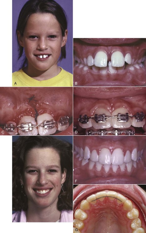
FIGURE 14-22 Management of a maxillary midline diastema. A, Facial appearance, showing the protruding maxillary incisors caught on the lower lip. B, Intraoral view before treatment. C, Teeth aligned and held tightly together with a figure-8 wire ligature, before frenectomy. D, Appearance immediately after frenectomy, using the conservative technique advocated by Edwards in which a simple incision is used to allow access to the interdental area, the fibrous connection to the bone is removed, and the frenal attachment is sutured at a higher level. E, Facial appearance 2 years after completion of treatment. F, Intraoral view 2 years after treatment. G, Bonded retainer, made with .0175 steel twist wire. It is important for the wire to be flexible enough to allow some displacement of the incisors in function—a rigid wire is much more likely to break loose.
The key to successful surgery is removal of the interdental fibrous tissue. It is unnecessary and, in fact, undesirable to excise a large portion of the frenum itself. Instead, a simple incision is used to allow access to the interdental area, the fibrous connection to the bone is removed, and the frenum is then sutured at a higher level.8
A maxillary midline diastema tends to recur, no matter how carefully the space was managed initially. The elastic gingival fiber network typically did not cross the midline in these patients, and the surgery interrupted any fibers that did cross. As a result, in this critical area the normal mechanism to keep teeth in contact is missing. A bonded fixed retainer is recommended (see Figure 14-22, G).
Leveling
The archwire design for leveling depends on whether there is a need for absolute intrusion of incisors, or whether relative intrusion is satisfactory. This important point is discussed in detail in Chapter 7, and the biomechanical considerations in obtaining intrusion are described in Chapters 8 and 9. As a general rule, relative intrusion is quite acceptable for adolescents; absolute intrusion is used for the most part in patients who are too old for relative intrusion to succeed. The discussion below assumes that an appropriate decision about the type of leveling has been made and focuses on the rather different techniques for leveling by relative intrusion (which is really differential elongation of premolars, for the most part) as contrasted to leveling by absolute intrusion of incisors (Figure 14-23).
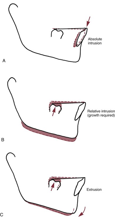
FIGURE 14-23 There are three possible ways to level a lower arch with an excessive curve of Spee: (A) absolute intrusion; (B) relative intrusion, achieved by preventing eruption of the incisors while growth provides vertical space into which the posterior teeth erupt; and (C) extrusion of posterior teeth, which causes the mandible to rotate down and back in the absence of growth. Note that the difference between B and C is whether the mandible rotates downward. This is determined by whether the ramus grows longer while the tooth movement is occurring.
Leveling by Extrusion (Relative Intrusion)
Leveling by extrusion can be accomplished with continuous archwires, simply by placing an exaggerated curve of Spee in the maxillary archwire and a reverse curve of Spee in the mandibular archwire. For most patients, it is necessary to replace the initial highly resilient alignment arch with a slightly stiffer one to complete the leveling. The choice of wires for this purpose is affected by whether the 18- or 22-slot edgewise appliance is being used.
18-Slot, Narrow Brackets
When preliminary alignment is completed, the second archwire is almost always 16 mil steel, with an exaggerated curve of Spee in the upper arch and a reverse curve in the lower arch. In most instances, this is sufficient to complete the leveling. A possible alternative is a 16 mil “potato chip” A-NiTi wire, preformed by the manufacturer with an extremely exaggerated curve. The extreme curve needed to generate enough force can lead to problems if patients miss appointments (i.e., the wire does not fail safe), so these wires are not recommended for routine use.
In some patients, particularly in nonextraction treatment of older patients who have little if any remaining growth, an archwire heavier than 16 mil steel is needed to complete the leveling of the arches. Rather than use an 18 mil archwire, it is usually quicker and easier to add an auxiliary leveling arch of 17 × 25 mil TMA or steel (Figure 14-24, A and B). This arch inserts into the auxiliary tube on the molar and is tied anteriorly beneath the 16 mil base arch. In essence, this augments the curve in the base arch and results in efficient completion of the leveling by the same mechanism as a single continuous wire. Although the auxiliary leveling arch looks like an intrusion arch (Figure 14-24, C and D), it differs in two important ways: the presence of a continuous rather than segmented base arch and the higher amount of force. Leveling will occur almost totally by extrusion as long as a continuous rather than segmented wire is in the bracket slots, while segmenting the arch makes intrusion possible (Figure 14-24, E and F).
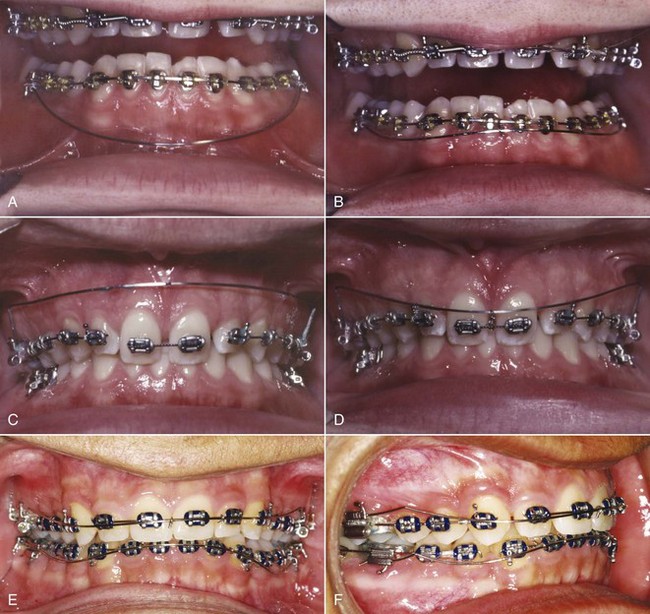
FIGURE 14-24 With a continuous archwire in place, intrusion is essentially impossible, but an auxiliary leveling archwire can be useful in augmenting the leveling force from a wire tied into the brackets. A, Auxiliary leveling wire prior to and after activation (B) by tying it beneath a continuous mandibular archwire. The appropriate force in this instance is approximately 150 gm, and the expected action is leveling by extruding the premolars rather than intruding the incisors. For absolute intrusion, light force (approximately 10 gm per tooth) is necessary. This requires use of archwire segments and an auxiliary intrusion arch. C, Intrusion arch prior to and after activation (D) by bending it downward and tying it to the segment to be intruded. The force delivered by the intrusion arch can be measured easily when it is brought down to the level at which it will be tied. E, Auxiliary leveling arches for extrusion in the maxillary arch and (F) for incisor-canine intrusion in the mandibular arch. Note that the mandibular base arch is segmented, creating a separate incisor segment, while a continuous archwire is in place in the maxillary arch and the auxiliary leveling arch is tied into the anterior brackets on top of it. Intrusion requires a segmented base arch and a light intrusive force (here, with six mandibular incisors in the anterior segment, approximately 50 gm would be used). Extrusion can be done with a segmented or continuous archwire, using about 50 gm/tooth in the segmented to be extruded.
It is sometimes said, as an argument in favor of the 22-slot appliance, that the wires available for use with the 18-slot appliance are not large enough to accomplish all necessary tooth movements. One of the few situations in which that may be true is in leveling with continuous archwires. Occasionally, a 20 mil steel wire with a reverse curve is required to complete the leveling in a patient with 22-slot brackets. The 18-slot equivalent is an auxiliary wire as suggested above.
22-Slot, Wider Brackets
For a typical patient using the 22-slot appliance, initial alignment with an A-NiTi wire (delivery of light force, not size, is the critical variable) is usually followed by a 16 mil steel wire with a reverse or accentuated curve and then by an 18 mil round wire to complete the leveling. This archwire sequence is nearly always adequate for completion of leveling, and it is unusual that 20 mil wire or an auxiliary archwire is required.
With either slot size, it is an error to place a rectangular archwire with an exaggerated curve of Spee in the mandibular arch because the curve creates torque to move the incisor roots lingually. Almost always that is undesirable. Inadvertent torque of lower incisor roots is one of the commonest mistakes with the edgewise appliance. The arch should be level before a rectangular wire is placed or step bends rather than a reverse curve of Spee should be placed in the rectangular wire, and torque in any rectangular wire should be monitored carefully. In the maxillary arch, however, a rectangular wire with an accentuated curve of Spee would be quite acceptable if lingual root torque of the upper incisors was needed, as it often is.
Leveling by Intrusion
Leveling by intrusion requires a mechanical arrangement other than a continuous archwire attached to each tooth (see Figure 14-24). The key to successful intrusion is light continuous force directed toward the tooth apex. It is necessary to avoid pitting intrusion of one tooth against extrusion of its neighbor, since in that circumstance, extrusion will dominate. This can be accomplished in two ways: (1) with continuous archwires that bypass the premolar (and frequently the canine) teeth and (2) with segmented archwires (so that there is no connection along the arch between the anterior and posterior segments) and an auxiliary depressing arch.
Bypass Arches
Using the bypass arches approach to intrusion is most useful for patients who will have some growth (i.e., who are in either the mixed or early permanent dentitions). Three different mechanical arrangements are commonly used, each based on the same mechanical principle: uprighting and distal tipping of the molars, pitted against intrusion of the incisors.
A classic version of this approach to leveling was seen in the first stage of the Begg technique in which the premolar teeth were bypassed and only a loose tie was made to the canine. Exactly the same effect can be produced in exactly the same way using the edgewise appliance, if the premolars and canines are bypassed with a “2 × 4” appliance (only 2 molars and 4 incisors included in the appliance setup)9 or if the wire in the bracket slots is segmented (Figure 14-25). A more flexible variation of the same basic idea was developed in Ricketts’ utility arch.10 In most cases, a utility arch formed from rectangular wire was placed into the brackets with slight labial root torque to control the inclination of the teeth as the incisors move labially while they intrude. This results in a complex mechanical system, however, that becomes difficult to control (see discussion in Chapter 9), and utility arches for intrusion have largely been replaced by the segmented arch approach described later.
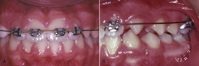
FIGURE 14-25 A and B, The long span of a 2 × 4 appliance makes it possible to create the light force necessary for incisor intrusion and also makes it possible to create unwanted side effects. The 2 × 4 appliance is best described as deceptively simple. When incisor intrusion is desired before other permanent teeth can be incorporated into the appliance, a transpalatal lingual arch for additional anchorage is a good idea.
Successful use of any type of bypass arch for leveling requires that the forces be kept light. This is accomplished in two ways: by selecting a small diameter archwire and by using a long span between the first molar and the incisors. Wire heavier than 16 mil steel should not be used, and Ricketts recommended a relatively soft 16 × 16 cobalt–chromium wire for utility arches to prevent heavy forces from being developed. A more modern recommendation would be 16 × 22 beta-Ti wire. Whatever the wire choice, overactivation of the vertical bends can cause loss of control of the molars in all three planes of space.
In contrast to leveling with continuous fully engaged archwires, the size of the edgewise bracket slot is largely irrelevant when bypass arches for leveling are used. Whether the appliance is 18- or 22-slot, the bypass arch should not be stiffer than 16 mil steel wire.
Two weaknesses of the bypass arch systems limit the amount of true intrusion that can be obtained. The first is that, except for some applications of the utility arch, only the first molar is available as posterior anchorage. This means that significant extrusion of that tooth may occur. In actively growing patients with a good facial pattern, this is not a major problem, but in nongrowing patients or those with a poor facial pattern in whom molar extrusion should be avoided, the lack of posterior anchorage compromises the ability to intrude incisors.
The second weakness is that the intrusive force against the incisors is applied anterior to the center of resistance and therefore the incisors tend to tip forward as they intrude (Figure 14-26). Without an extraction space, forward movement of the incisors is an inevitable consequence of leveling, but in extraction cases when the incisors are to be retracted, this becomes an undesirable side effect. An anchor bend at the molar in a bypass arch creates a space-closing effect that somewhat restrains forward incisor movement (Figure 14-27), but this also tends to bring the molar forward, straining the posterior anchorage. A utility arch can be activated (like a closing loop) to keep the incisors from moving forward and has the additional benefit of a rectangular cross-section anteriorly so that tipping can be controlled, but the result is still a strain on posterior anchorage, and, more importantly, it results in an unknown intrusion force that may be too heavy or too light (see Figure 9-39).
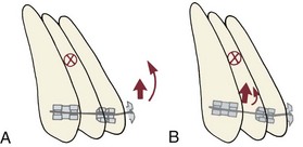
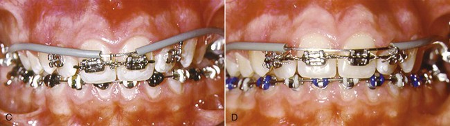
FIGURE 14-26 A, When the incisor segment is viewed from a lateral perspective, the center of resistance (X) is lingual to the point at which an archwire attaches to the teeth. For this reason, the incisors tend to tip forward when an intrusive force is placed at the central incisor brackets. B, Tying an intrusion arch distal to the midline (for instance, between the lateral incisor and canine, as shown here) moves the line of force more posteriorly and therefore closer to the center of resistance. This diminishes or eliminates the moment that causes facial tipping of the teeth as they intrude. C, Intrusion arch tied in the midline as only the central incisors are intruded, so that the incisors will tip facially as they intrude. D, In the same patient later, an intrusion arch now is tied between the central and lateral incisors to intrude all four incisors while reducing the amount of facial tipping.
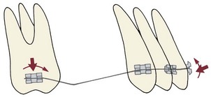
FIGURE 14-27 Diagrammatic representation of the forces for a leveling arch that bypasses the premolars, with an anchor bend mesial to the molars. A force system is created that elongates the molars and intrudes the incisors. The wire tends to slide posteriorly through the molar tubes, tipping the incisors distally at the expense of bodily mesial movement of the molars. An archwire of this design is used in the first stage of Begg treatment but also can be used in edgewise systems. A long span from the molars to the incisors is essential.
The segmented arch approach developed by Burstone, which overcomes these limitations, is recommended for maximum control of the anterior and posterior segments of the dental arch. Data now exist to document equivalent long-term stability with leveling by continuous archwires versus sectional wires in the segmented arch technique.11
Segmented Arches
The segmented arch approach allows attachments on all the teeth and so provides better control of anchorage. For intrusion of anterior teeth, it depends on establishing stabilized posterior segments and controlling the point of force application against an anterior segment. This technique requires auxiliary rectangular tubes on first molars, in addition to the regular bracket or tube. After preliminary alignment, a full dimension rectangular archwire is placed in the bracket slots of teeth in the buccal segment, which typically consists of the second premolar, first molar, and second molar. This connects these teeth into a solid unit. In addition, a heavy lingual arch (36 mil round or 32 × 32 rectangular steel wire) is used to connect the right and left posterior segments, further stabilizing them against undesired movement. A resilient anterior segmental wire is used to align the incisors, while the posterior segments are being stabilized.
For intrusion, an auxiliary arch placed in the auxiliary tube on the first molar is used to apply intrusive force against the anterior segment (see Figure 14-26). This arch should be made of rectangular wire that will not twist in the auxiliary tube: either 18 × 25 steel wire with a  -turn helix, 17 × 25 or 19 × 25 TMA wire without a helix, or a preformed M-NiTi intrusion arch is acceptable. This auxiliary arch is adjusted so that it lies gingival to the incisor teeth when passive and applies a light force (approximately 10 gm per tooth, depending on root size) when it is brought up beneath the brackets of the incisors. It is tied underneath or in front of the incisor brackets but not into the bracket slots, which are occupied by the anterior segment wire.
An auxiliary intrusion arch can be placed while a light resilient anterior segment is being used to align malposed incisors, but usually it is better to wait to add it until incisor alignment has been achieved and a heavier anterior segment wire has been installed. A braided rectangular steel wire or a rectangular TMA wire is usually the best choice for the anterior segment while active intrusion with an auxiliary arch is being carried out.
Two strategies can be used with segmented arches to prevent forward movement of the incisors as they are intruded. The first is the same as with bypass arches: a space-closing force can be created by tying the auxiliary arch back against the posterior segments. Even with stabilized posterior segments, this produces some strain on posterior anchorage.
The second and usually preferable strategy is to vary the point of force application against the incisor segment. If the anterior segment is considered a single unit (which is reasonable when a stiff archwire connects the teeth within the segment), the center of resistance is located as shown in Figure 14-26. Tying the depressing arch distal to the midline, between the central and lateral incisors or distal to the laterals, also brings the point of force application more posteriorly so that the force is applied more nearly through the center of resistance. This prevents anterior tipping of the incisor segment without causing anchorage strain, but the auxiliary wire must be tied quite loosely at both points to avoid the risk of inadvertently creating a two-couple system.
Even with the control of posterior anchorage obtained by placing rectangular stabilizing segments and an anchorage lingual arch, the reaction to intrusion of incisors is extrusion and distal tipping of the posterior segments. With careful attention to appropriate technique with the segmented arch approach, it is possible to produce approximately four times as much incisor intrusion as molar extrusion in nongrowing adults. Although successful intrusion can be obtained with round bypass arches, the ratio of anterior intrusion to posterior extrusion is much less favorable.
It is quite feasible to intrude asymmetrically, which requires only adjusting the teeth that are placed in stabilizing and intrusion segments and tying the auxiliary intrusion arch in the area where intrusion is required (Figure 14-28). If intrusion is desired only on one side, either a cantilevered auxiliary wire extending from one molar or a molar-to-molar auxiliary arch can be used. The key is tying the auxiliary arch at the point where intrusion is desired.
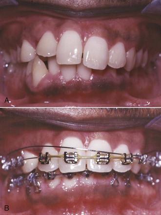
FIGURE 14-28 A, In this adult patient, the maxillary left central and lateral incisors and particularly the canine had supererupted. Asymmetric intrusion of those teeth was needed. B, An auxiliary intrusion arch delivering about 30 gm was tied to the elongated canine, while preliminary alignment with an A-NiTi wire was employed. The result was leveling of the maxillary arch with a component of intrusion on the elongated side. Asymmetric intrusion can be accomplished either by asymmetric activation of an intrusion arch that spans from one first molar to the other or by use of a cantilever intrusion arch on one side only.
Skeletal Anchors
Skeletal anchorage, using bone anchors or bone screws (discussed in detail in Chapters 10 and 18), offers the possibility of intrusion of posterior as well as anterior teeth and eliminates the problem of controlling unwanted movement of anchor teeth (Figures 14-29 and 14-30). Is it worth it to subject patients to the surgery necessary to place and remove the anchors or screws? This question would be decided on the basis of two things: the effectiveness of the anchorage provided by the skeletal units and the reaction of the patients to both the surgery to place the anchors and the experience of living with them during orthodontic treatment.
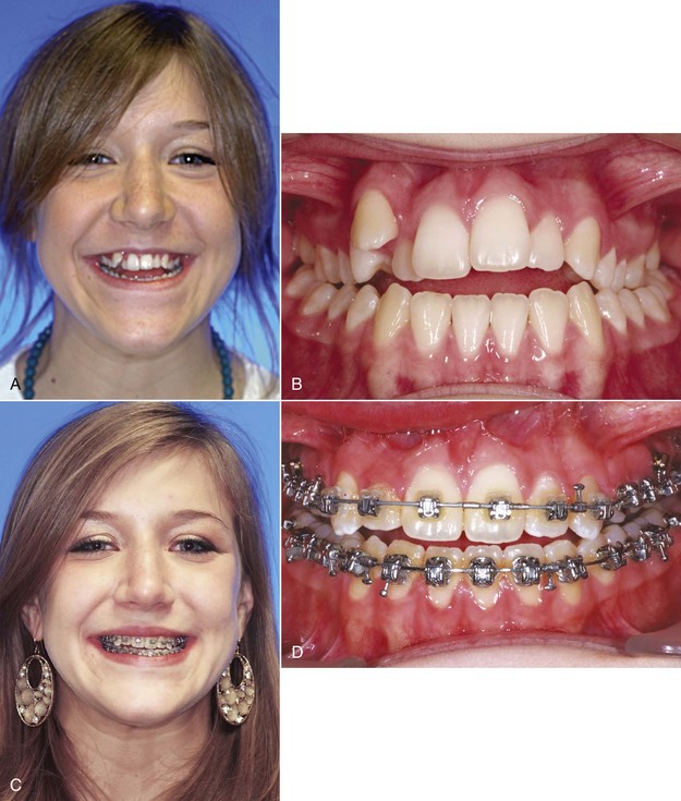
FIGURE 14-29 A and B, An unsightly crowded-out maxillary left canine, posterior crossbite, and anterior open bite in a 15-year-old girl. The treatment plan was to intrude the maxillary posterior teeth using 8-mm-long alveolar bone screws bilaterally between the roots of the maxillary first molar and second premolar as anchorage and align the maxillary arch with transverse expansion. C and D, Progress photos showing corrected alignment and decreased open bite. E and F, Completion of treatment after 7 months of posterior intrusion (24 months total treatment). (Courtesy Dr. N. Scheffler.)
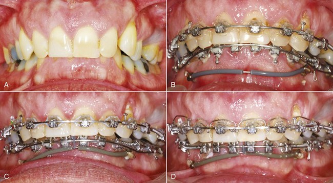
FIGURE 14-30 A, Extreme anterior deep bite in a 53-year-old male with short anterior face height, supererupted lower incisors, previously extracted first premolars, and a Class II division 2 pattern of the maxillary incisors. The treatment plan included leveling of the mandibular arch by extrusion of the posterior teeth and intrusion of the anteriors, advancement and torquing of the incisors in both arches, and opening spaces for the missing premolars, using a continuous rather than segmented main archwire. B, The mandibular leveling auxiliary wire, anchored to 6 mm alveolar bone screws bilaterally, augments the leveling force provided by the main archwire. The tubing is to prevent lip and gingival irritation. C, One month progress. D, Bite opening largely achieved after 4 months. Note the auxiliary maxillary torquing arch, which will tip the maxillary incisors anteriorly unless it is tied back posteriorly, allowing control of the amount of torque versus tipping. (Courtesy Dr. N. Scheffler.)
At this point, it is clear that temporary skeletal anchor units can be quite effective. Although implants designed to support crowns or bridges can be used as anchor units, the osseointegration that is required for long-term success with them is undesirable for anchor units that are planned for removal later. Removing an integrated implant can be a difficult surgical procedure that is much harder to perform and endure than simply backing out bone screws and lifting an anchor off the bone surface. The amount of force that can be placed against a bone screw is well within the force magnitude needed for tooth movement, especially when the objective is intrusion and light force is the key to producing it. Bone screws can be loaded immediately. They may become loose, and there appears to be about a 10% chance that this will occur. Bone anchors held in place by two or (better) three screws are quite unlikely to become too loose to be effective. The discussion at the end of Chapter 10 reviews the types of skeletal anchor units and the surgery to place and remove them, and applications of skeletal anchorage in treatment of several types of problems are illustrated in Chapter 18.
The reaction of patients and their doctors to temporary skeletal anchorage is remarkably favorable (see discussion in Chapter 18 and Figures 18-50 and 18-51).12 To the surgeons who place miniplates for multiscrew anchorage, the surgery is less difficult and takes less time than they initially thought. To the patients, the surgery for miniplates or bone screws is less painful than they expected, and almost all say that it is not difficult to tolerate the presence of screws or miniplates on the facial surface of the dental arch or against the zygomatic buttress, where they would be put for intrusion of teeth. It is particularly interesting that a few of the patients in this study previously had headgear to attempt to control excessive vertical maxillary growth and then had bone anchors for posterior intrusion. They unanimously said that headgear was more difficult to tolerate.
Although there is as yet no long-term experience with temporary skeletal anchorage for leveling, it appears that when intrusion of teeth is needed in nongrowing patients, bone screws or bone anchors offer an excellent way to simplify the treatment and improve its effectiveness. Nongrowing patients, of course, are by far the major group who need absolute intrusion—relative intrusion suffices for most patients prior to the end of vertical growth in late adolescence. Skeletal anchorage already is the preferred approach, particularly for patients who need a few millimeters of posterior intrusion (see Figure 14-29) or a considerable amount of anterior intrusion (see Figure 14-30).
At the conclusion of the first stage of treatment, the arches should be level and teeth should be aligned to the point that rectangular steel archwires can be placed without an exaggerated curve and without generating excessive forces. The duration of the first stage, obviously, will be determined by the severity of both the horizontal and vertical components of the initial malocclusion. For some patients, only a single initial archwire will be required, while for others, several months may be needed for alignment and several more months for leveling, before the next stage can begin. As a principle of treatment, it is important not to move to the second stage until both leveling and alignment are adequate.
References
1. Begg, PR, Kesling, PC. Begg Orthodontic Theory and Technique. Philadelphia: WB Saunders; 1977.
2. Bolender, Y, Vernière, A, Rapin, C, et al. Torsional superelasticity of NiTi archwires. Angle Orthod. 2010;80:1100–1109.
3. Sarver, DM, Johnston, MW. Skeletal changes in vertical and anterior displacement of the maxilla with bonded rapid palatal expansion appliances. Am J Orthod Dentofac Orthop. 1989;95:462–466.
4. Haney, E, Gansky, SA, Lee, JS, et al. Comparative analysis of traditional radiographs and cone-beam computed tomography volumetric images in the diagnosis and treatment planning of maxillary impacted canines. Am J Orthod Dentofac Orthop. 2010;137:590–597.
5. Alqerban, A, Jacobs, R, Fieuws, S, et al. In-vitro comparison of two cone beam computed tomographic systems versus panoramic imaging for localization of impacted maxillary canines and detection of root resorption. Eur J Orthod. 2011;33:93–102.
6. Vermette, ME, Kokich, VG, Kennedy, DB. Uncovering labially impacted teeth—apically positioned flap and closed-eruption techniques. Angle Orthod. 1995;65:23–32.
7. Tejera, TJ, Blakey, GH. Surgical uprighting and repositioning. In: Fonseca, RM, Frost, DE, Hersh, EV, et al, eds. Oral and Maxillofacial Surgery: Anesthesia/Dentoalveolar Surgery/Office Management, vol 1. Philadelphia: WB Saunders; 2000.
8. Edwards, JG. Soft tissue surgery to alleviate orthodontic relapse. Dent Clin North Am. 1993;37:205–225.
9. Isaacson, RJ, Lindauer, SJ, Rubenstein, LK. Activating a 2 × 4 appliance. Angle Orthod. 1993;63:17–24.
10. Ricketts, RW, Bench, RW, Gugino, CF, et al. Bioprogressive Therapy. Denver: Rocky Mountain Orthodontics; 1979.
11. Preston, CB, Maggard, MB, Lampasso, J, et al. Long-term effectiveness of the continuous and the sectional archwire techniques in leveling the curve of Spee. Am J Orthod Dentofac Orthop. 2008;133:550–555.
12. Cornelis, MA, Scheffler, NR, DeClerck, H, et al. Patients’ and orthodontists’ perceptions of miniplates used for temporary skeletal anchorage: a prospective study. Am J Orthod Dentofac Orthop. 2008;133:18–24.