Chapter 2 Recognizing Normal Chest Anatomy and a Technically Adequate Chest Radiograph
 In order to become more comfortable interpreting chest radiographs, you first need to be able to recognize fundamental, normal anatomy so you can differentiate it from what is abnormal. Second, you have to be able to quickly determine if a study is technically adequate so that you don’t mistake technical deficiencies for abnormalities. Third, if you decide a finding is abnormal, you need to have some strategy for deciding what the abnormality is. First (and second) things first: This chapter will familiarize you with normal chest radiographic anatomy and enable you to evaluate the technical adequacy of a radiograph by helping you become more familiar with the diagnostic pitfalls certain technical artifacts can introduce.
The Normal Frontal Chest Radiograph
Vessels and bronchi: normal lung markings
Pleura: normal anatomy
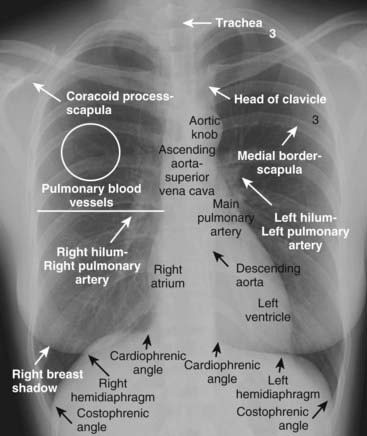
Figure 2-1 Well-exposed frontal view of a normal chest.
Notice how the spine is just visible through the heart shadow. Both the right and left lateral costophrenic angles are sharply and acutely angled. The white line demarcates the approximate level of the minor or horizontal fissure, which is usually visible on the frontal view because it is seen en face. There is no minor fissure on the left side. The white circle contains lung markings that are blood vessels. Note that the left hilum is normally slightly higher than the right. The white “3” lies on the posterior 3rd rib while the black “3” lies on the anterior 3rd rib.
The Lateral Chest Radiograph
As part of the standard two-view chest examination, patients usually have an upright, frontal chest radiograph and an upright, left lateral view of the chest. A left lateral chest x-ray (the patient’s left side is against the film) is of great diagnostic value but is sometimes ignored by beginners because of their lack of familiarity with the findings visible in that projection. Why look at the lateral chest?

Figure 2-2 Normal left lateral chest radiograph.
A clear space is present behind the sternum (solid white arrow). The hila produce no discrete shadow (white circle). The vertebral bodies are approximately of equal height and their endplates are parallel to each other (double white arrows). The posterior costophrenic angles (solid black arrow) are sharp. Notice how the thoracic spine appears to become blacker (darker) from the shoulder girdle (black star) to the diaphragm because there is less dense tissue for the x-ray beam to traverse at the level of the diaphragm. The heart normally touches the anterior aspect of the left hemidiaphragm and usually obscures (silhouettes) it. The superior surface of the right hemidiaphragm is frequently seen continuously from back to front (dotted black arrow) because it is not obscured by the heart. Notice the normal space posterior to the heart and anterior to the spine; this will be important in assessing cardiomegaly (Chapter 9). The black line represents the approximate location of the major or oblique fissure; the white line is the approximate location of the minor or horizontal fissure. Both are visible because they are seen en face on the lateral view.
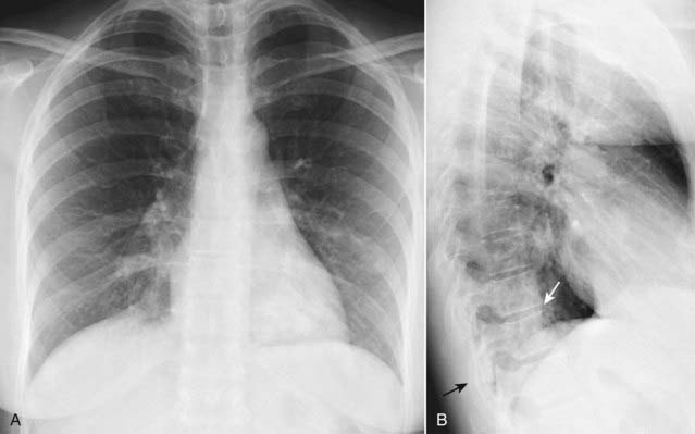
Frontal (A) and lateral (B) views of the chest demonstrate airspace disease on the lateral film (B) in the left lower lobe that may not be immediately apparent on the frontal film (look closely at A and you may see the pneumonia in the left lower lobe behind the heart). Normally, the thoracic spine appears to get “blacker” as you view it from the neck to the diaphragm because there is less dense tissue for the x-ray beam to traverse just above the diaphragm than in the region of the shoulder girdle (see also Fig. 2-2). In this case, a left lower lobe pneumonia superimposed on the lower spine in the lateral view (solid white arrow) makes the spine appear “whiter” (more dense) just above the diaphragm. This is called the spine sign. Note that on a well-positioned lateral projection, the right and left posterior ribs almost superimpose on each other (solid black arrow), a sign of a true lateral.
Five Key Areas on the Lateral Chest X-Ray (Fig. 2-2 and Table 2-1)
TABLE 2-1 THE LATERAL CHEST: A QUICK GUIDE OF WHAT TO LOOK FOR
| Region | What You Should See |
|---|---|
| Retrosternal clear space | Lucent crescent between sternum and ascending aorta |
| Hilar region | No discrete mass present |
| Fissures | Major and minor fissures should be pencil-point thin, if visible at all |
| Thoracic spine | Rectangular vertebral bodies with parallel end plates; disk spaces maintain height from top to bottom of thoracic spine |
| Diaphragm and posterior costophrenic sulci | Right hemidiaphragm slightly higher than left; sharp posterior costophrenic sulci |
The Retrosternal Clear Space
Normally, a relatively lucent crescent is present just behind the sternum and anterior to the shadow of the ascending aorta.
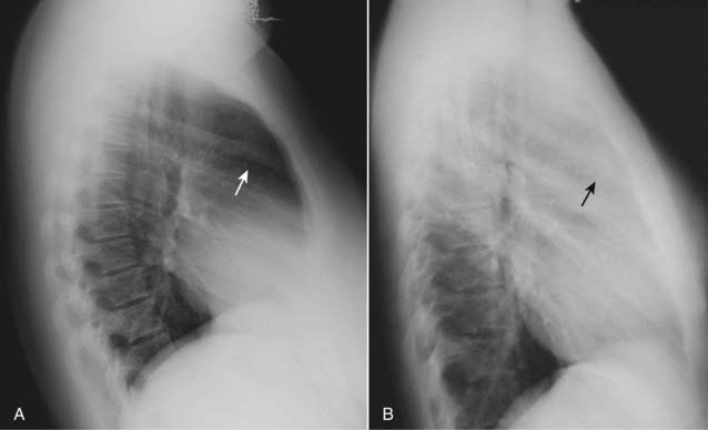
Figure 2-4 Anterior mediastinal adenopathy.
A normal lateral (A) shows a clear space behind the sternum (solid white arrow). Left lateral view of the chest (B) demonstrates soft tissue that is filling in the normal clear space behind the sternum (solid black arrow). This represents anterior mediastinal lymphadenopathy in a patient with lymphoma. Adenopathy is probably the most frequent reason the retrosternal clear space is obscured. Thymoma, teratoma, and substernal thyroid enlargement also can produce anterior mediastinal masses but do not usually produce exactly this appearance.
 Pitfall: Be careful not to mistake the soft tissue of the patient’s superimposed arms for “filling-in” of the clear space. Although patients are asked to hold their arms over their head for a lateral chest exposure, many are too weak to raise their arms.
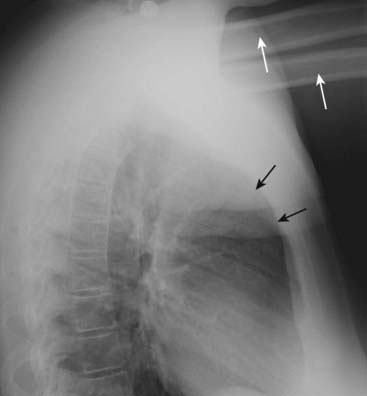
Figure 2-5 Arms obscure retrosternal clear space.
In this example, the patient was not able to hold her arms over her head for the lateral chest examination, as patients are instructed to do in order to eliminate the shadows of the arms from overlapping the lateral chest. The humeri are clearly visible (solid white arrows) so even though the soft tissue of the patient’s arms appears to fill in the retrosternal clear space (solid black arrows), this should not be mistaken for an abnormality such as anterior mediastinal adenopathy (see Fig. 2-4).
The Hilar Region
The hila may be difficult to assess on the frontal view, especially if both hila are slightly enlarged, since comparison with the opposite normal side is impossible. The lateral view may help. Most of the hilar densities are made up of the pulmonary arteries. Normally, no discrete mass is visible in the hila on the lateral view. When there is a hilar mass, such as might occur with enlargement of hilar lymph nodes, the hilum (or hila) will cast a distinct, lobulated masslike shadow on the lateral radiograph (Fig. 2-6).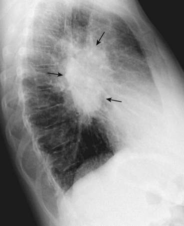
Figure 2-6 Hilar mass on lateral radiograph.
Left lateral view of the chest shows a discrete lobulated mass in the region of the hila (solid black arrows). Normally, the hila do not cast a shadow that is easily detectable on the lateral projection. This patient had bilateral hilar adenopathy from sarcoidosis but any cause of hilar adenopathy or a primary tumor in the hilum would have a similar appearance.
The Fissures
On the lateral film, both the major (oblique) and minor (horizontal) fissures may be visible as a fine, white line (about as thick as a line made with the point of a sharpened pencil).
The fissures demarcate the upper and lower lobes on the left and the upper, middle, and lower lobes on the right. When a fissure contains fluid or develops fibrosis from a chronic process, it will become thickened (Fig. 2-7).
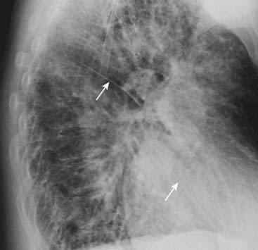
Figure 2-7 Fluid in the major fissures.
Left lateral view of the chest shows thickening of both the right and left major fissures (solid white arrows). This patient was in congestive heart failure and this thickening represents fluid in the fissures. Normally, the fissures are either invisible or, if visible, they are fine, white lines of uniform thickness no larger than a line made with the point of a sharpened pencil. The major or oblique fissure runs from the level of the 5th thoracic vertebral body to a point on the anterior diaphragm about 2 cm behind the sternum. Notice the increased interstitial markings that are visible throughout the lungs and are due to fluid in the interstitium of the lung.
The Thoracic Spine
Normally, the thoracic vertebral bodies are roughly rectangular in shape, and each vertebral body’s endplate parallels the endplate of the vertebral body above and below it. Each intervertebral disk space becomes slightly taller than or remains the same as the one above it throughout the thoracic spine. Degeneration of the disk can lead to narrowing of the disk space and the development of small, bony spurs (osteophytes) at the margins of the vertebral bodies. When there is a compression fracture, most often from osteoporosis, the vertebral body loses height. Compression fractures very commonly first involve depression of the superior endplate of the vertebral body (Fig. 2-8). Don’t forget to look at the thoracic spine when studying the lateral chest radiograph for valuable clues about systemic disorders (see Chapter 24).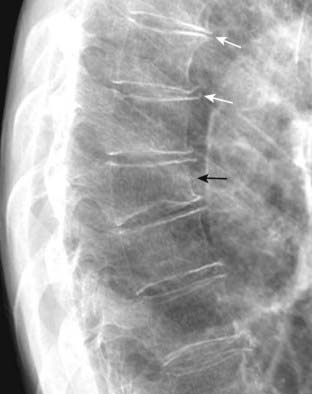
Figure 2-8 Osteoporotic compression fracture and degenerative disk disease.
Don’t forget to look at the thoracic spine when studying the lateral chest radiograph for valuable information about a host of systemic diseases (see Chapter 24). In this study, loss of stature of the 8th thoracic vertebral body is due to osteoporosis (solid black arrow). Compression fractures frequently involve the superior endplate first. Small osteophytes are present at multiple levels from degenerative disk disease (solid white arrows).
The Diaphragm and Posterior Costophrenic Sulci
Because the diaphragm is composed of soft tissue (muscle) and the abdomen below it contains soft tissue structures like the liver and spleen, only the upper border of the diaphragm, abutting the air-filled lung, is usually visible on conventional radiographs. Even though we have one diaphragm that separates the thorax from the abdomen, we usually do not see the entire diaphragm from side-to-side on conventional radiographs because of the position of the heart in the center of the chest.
How to tell the right from the left hemidiaphragm on the lateral radiograph:
The posterior costophrenic angles (posterior costophrenic sulci)
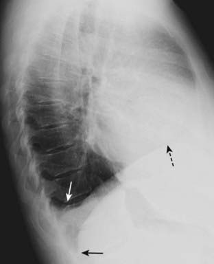
Figure 2-9 Blunting of the posterior costophrenic sulcus by a small pleural effusion.
Left lateral view of the chest shows fluid blunting the posterior costophrenic sulcus (solid white arrow). The other posterior costophrenic angle (solid black arrow) is sharp. The pleural effusion is on the right side because the hemidiaphragm involved can be traced anteriorly farther forward (dotted black arrow) than the other hemidiaphragm (the left), which is normally silhouetted by the heart and not visible anteriorly.
Evaluating the Chest Radiograph for Technical Adequacy
Evaluating five technical factors will help you determine if a chest radiograph is adequate for interpretation or whether certain artifacts may have been introduced that can lead you astray (Table 2-2):
TABLE 2-2 WHAT DEFINES A TECHNICALLY ADEQUATE CHEST RADIOGRAPH?
| Factor | What You Should See |
|---|---|
| Penetration | The spine should be visible through the heart |
| Inspiration | At least eight to nine posterior ribs should be visible |
| Rotation | Spinous process should fall equidistant between the medial ends of the clavicles |
| Magnification | AP films (mostly portable chest x-rays) will magnify the heart slightly |
| Angulation | Clavicle normally has an “S” shape and superimposes on the 3rd or 4th rib |
Penetration
Unless x-rays adequately pass through the body part being studied, you may not visualize everything necessary on the image produced.
Pitfalls of underpenetration (inadequate penetration): You can tell a frontal chest radiograph is underpenetrated (too light) if you are not able to see the spine through the heart (Fig. 2-10). Underpenetration can introduce at least two errors into your interpretation.

Figure 2-10 Underpenetrated frontal chest radiograph.
The spine (solid black arrow) is not visible through the cardiac shadow. The left hemidiaphragm is also not visible (dotted black arrows) and the degree of underpenetration makes it impossible to differentiate between actual disease at the left base versus nonvisualization of the left hemidiaphragm from underpenetration. A lateral radiograph of the chest would help to differentiate between artifact of technique and true disease.
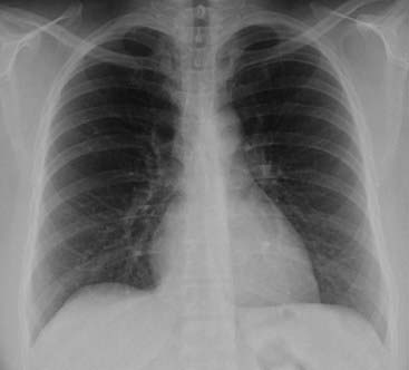
Figure 2-11 Overpenetrated frontal chest radiograph.
Overpenetration makes lung markings difficult to see, mimicking some of the findings in emphysema or possibly suggesting a pneumothorax. How lucent (dark) the lungs appear on a radiograph is a poor way of evaluating for the presence of emphysema because of artifacts introduced by technique. In emphysema, the lungs are frequently hyperinflated and the diaphragm flattened (see Chapter 12). In order to diagnose a pneumothorax, you should see the pleural white line (see Chapter 8).
Inspiration
A full inspiration ensures a reproducible radiograph from one time to the next and eliminates artifacts that may be confused for or obscure disease.

The posterior ribs are numbered in this photograph. Ten posterior ribs are visible above the right hemidiaphragm, an excellent inspiration. In most hospitalized patients, eight to nine visible posterior ribs in the frontal projection is an inspiration that is adequate for accurate interpretation of the image. When counting ribs, make sure you don’t miss counting the 2nd posterior rib, which frequently overlaps the 1st rib.
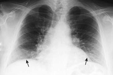
Figure 2-13 Sub-optimal inspiration.
Only eight posterior ribs are visible on this frontal chest radiograph. A poor inspiration may “crowd” and therefore accentuate the lung markings at the bases (solid black arrows) and may make the heart seem larger than it actually is. The crowded lung markings may mimic the appearance of aspiration or pneumonia. A lateral chest radiograph should help in eliminating the possibility, or confirming the presence, of basilar airspace disease suspected from the frontal radiograph.
Rotation
Significant rotation (the patient turns the body to one side or the other) may alter the expected contours of the heart and great vessels, the hila, and hemidiaphragms. The easiest way to assess whether the patient is rotated toward the left or right is by studying the position of the medial ends of each clavicle relative to the spinous process of the thoracic vertebral body between the clavicles (Fig. 2-14).
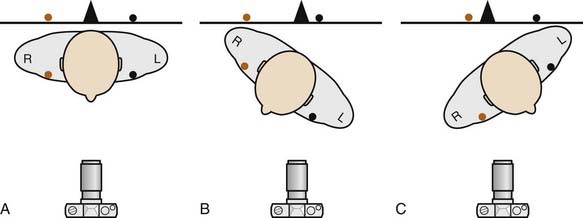
Figure 2-14 How to determine if the patient is rotated.
In A, the patient is not rotated and the medial ends of the right (orange dot) and left (black dot) clavicles are projected on the radiograph (black line) equidistant from the spinous process (black triangle). In B, the patient is rotated toward his own right. Notice how the medial end of the left clavicle (black dot) is projected closer to the spinous process than is the medial end of the right clavicle (orange dot). In C, the patient is rotated toward his own left. The medial end of the right clavicle (orange dot) is projected closer to the spinous process than is the medial end of the left clavicle (black dot). The camera icon depicts this as an AP projection, but the same relationships would be true for a PA projection as well. Figure 2-15 shows how this applies to radiographs.
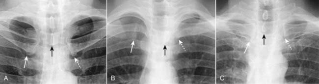
Figure 2-15 How to evaluate for rotation.
A, Close-up view of the heads of the clavicles demonstrates that each (white arrows) is about equidistant from the spinous process of the vertebral body between them (black arrow). This indicates the patient is not rotated. B, Close-up view of the heads of the clavicles in a patient rotated toward his own right (remember that you are viewing the study as if the patient were facing you). The spinous process (black arrow) is much closer to the left clavicular head (dotted white arrow) than it is to the right clavicular head (solid white arrow). C, Close-up view of the heads of the clavicles in a patient rotated toward his own left. The spinous process (black arrow) is much closer to the right clavicular head (solid white arrow) than it is to the left (dotted white arrow).
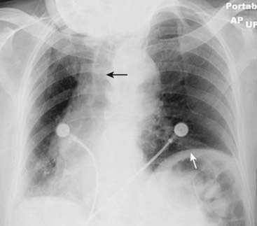
Figure 2-16 Distorted appearance due to severe rotation.
Frontal chest radiograph of a patient markedly rotated toward her own right. Notice how the left hemidiaphragm, being farther from the cassette than the right hemidiaphragm because of the rotation, appears higher than it normally would (solid white arrow). The heart and the trachea (solid black arrow) appear displaced into the right hemithorax because of the rotation.
Magnification
Depending on the position of the patient relative to the imaging cassette, magnification can play a role in assessing the size of the heart.
 The closer any object is to the surface on which it is being imaged, the more true to its actual size the resultant image will be. As a corollary, the farther any object is from the surface on which it is being imaged, the more magnified that object will appear.
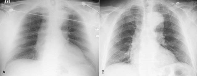
Figure 2-17 Effect of positioning on magnification of the heart.
Frontal chest radiograph done in the AP projection (A) shows the heart to be slightly larger than in B, which is the same patient’s chest exposed minutes later in the PA projection. Because the heart lies anteriorly in the chest, it is farther from the imaging surface in A and is therefore magnified more than in B, in which the heart is closer to the imaging surface. In actual practice, there is very little difference in the heart size between an AP and PA exposure so long as the patient has taken an equal inspiration on both.
Angulation
Normally, the x-ray beam passes horizontally (parallel to the floor) for an upright chest study, and in that position, the plane of the thorax is perpendicular to the x-ray beam. Hospitalized patients, in particular, may not be able to sit completely upright in bed so that the x-ray beam may enter the thorax with the patient’s head and thorax tilted backwards.
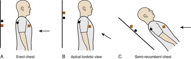
Figure 2-18 Diagram of apical lordotic effect.
In A, the x-ray beam (black arrow) is correctly oriented perpendicular to the plane of the cassette (black line). The orange square symbolizes an anterior structure (like the clavicles) and the black circle a posterior structure (like the spine). In B, the x-ray beam is angled upward, which is the manner in which an apical lordotic view of the chest is obtained. The x-ray beam is no longer perpendicular to the cassette, which has the effect of projecting anterior structures higher on the radiograph than posterior structures. The position of the x-ray beam and patient in C leads to the exact same end result as B and is how semirecumbent, bedside studies are frequently obtained on patients who are not able to sit or stand upright. Anterior structures in C are projected higher than posterior structures.

Figure 2-19 Apical lordotic chest radiograph.
An apical lordotic view of the chest is now most frequently obtained inadvertently in patients who are semirecumbent at the time of the study. Notice how the clavicles are projected above the first ribs and their usual “S” shape is now straight (solid white arrows). The lordotic view also distorts the shape of the heart and produces spurious obscuration of the left hemidiaphragm (solid black arrow). Unless the artifacts of technique are understood, these findings could be mistaken for disease that doesn’t exist.
 Weblink
Registered users may obtain more information on Recognizing Normal Chest Anatomy and a Technically Adequate Chest Radiograph on StudentConsult.com.
 Take-Home Points
Recognizing Normal Chest Anatomy and a Technically Adequate Chest Radiograph
Virtually all of the lung markings are composed of pulmonary blood vessels; the minor fissure may be visible on both the frontal and lateral views, the major fissure only on the lateral.
The lateral chest radiograph can provide invaluable information and should always be studied when available.
Five key areas to inspect on the lateral projection include the retrosternal clear space, the hilar region, the fissures, the thoracic spine, and the diaphragm/posterior costophrenic sulci.
Five parameters define an adequate chest examination, and recognition of them is important to accurately differentiate abnormalities from technically produced artifacts.
They are penetration, inspiration, rotation, magnification, and angulation.
If the chest is adequately penetrated, you should be able to see spine through the heart; underpenetrated (too light) studies obscure the left lung base and tend to spuriously accentuate the lung markings, while overpenetrated studies (too dark) may mimic emphysema or pneumothorax.
If the patient has taken an adequate inspiration, you should see at least eight to nine posterior ribs above the diaphragm; poor inspiratory efforts may mimic basilar lung disease and may make the heart appear larger.
The spinous process should fall equidistant between the medial ends of the clavicles to indicate the patient is not rotated; rotation can introduce numerous artifactual anomalies affecting the contour of the heart and the appearance of the hila and diaphragm.
Anteroposterior (AP) films (mostly portable chest x-rays) will magnify the heart slightly compared to the standard posteroanterior (PA) chest radiograph (usually done in the radiology department).
Frontal views of the chest obtained with the patient semiupright in bed (tilted backwards) may produce apical lordotic images that distort normal anatomy.