Chapter 14 Imaging the Extremities
Evaluation of extremity injuries and nontraumatic abnormalities is one of the most common indications for diagnostic imaging in the emergency department. This chapter considers the modalities available for evaluation of a range of extremity conditions, including fractures, dislocations, arterial and venous vascular anomalies, infections, and foreign bodies. We review standard fracture terminology and discuss the interpretation of common imaging tests by the emergency physician. We also discuss selected indications for diagnostic imaging using validated clinical decision rules. We review the Salter-Harris classification of pediatric fractures. We highlight high-risk extremity injuries that may be difficult to diagnose by physical examination and are sometimes missed despite diagnostic imaging. We also describe and illustrate with detailed figures the most common and serious extremity conditions.
Chapter 15 highlights the use of magnetic resonance imaging (MRI) and computed tomography (CT) in evaluation of wrist and hip injuries. Hip dislocations, fractures, and pediatric pathology including slipped capital femoral epiphysis and Legg-Calvé-Perthes disease are discussed in Chapter 13.
Imaging Modalities
X-ray
By far the most common imaging modality for the extremities is x-ray. X-ray is useful in evaluation of fractures, dislocations, bony tumors, soft-tissue air, and radiopaque foreign bodies. Although x-ray can give some indication of the presence of joint effusions and soft-tissue pathology, its sensitivity is quite limited for these indications.
Computed Tomography
CT scan has seen growing applications in recent years for evaluation of complex periarticular fractures, such as fractures of the tibial plateau, and for evaluation of areas with a confluence of overlapping bones that make evaluation with plain x-ray difficult. Examples include bony injuries to the ankle and wrist. The three-dimensional capability of CT scan is particularly useful in demonstrating the relationship of fracture fragments and dislocations. Modern CT scan has submillimeter resolution, allowing detection of even subtle nondisplaced fractures in many cases. Technical features of CT relevant to fracture detection are discussed in detail in Chapter 15.
CT angiography (CTA) has also become a first-line imaging modality for evaluation of extremity arterial injuries and arterial insufficiency caused by atherosclerotic disease. CT venography has become an option for evaluation of deep venous thrombosis (DVT), as described in Chapter 7. CT is highly sensitive for detection of soft-tissue gas and foreign bodies that differ in density from surrounding tissues.
Magnetic Resonance Imaging
The excellent soft-tissue contrast of MRI makes it a first-line imaging modality for evaluation of ligamentous, tendon, cartilage, and muscle injury. However, these injuries rarely require specific emergent treatment, and in most cases MRI can be deferred to the outpatient setting. MRI is also exquisitely sensitive for detection of soft-tissue foreign bodies and serves an important role when a foreign body is suspected but not detected with x-ray. Ironically, although MRI is quite insensitive for detection of cortical bone because of the absence of resonating protons, MRI has become a preferred test in evaluation of subtle fractures of the hip and scaphoid bone, because it can detect marrow edema associated with these injuries. The evidence for use of MRI in this setting is discussed in detail in Chapter 15. Magnetic resonance angiography (MRA) also offers an alternative to CTA for evaluation of extremity vascular conditions. In general, MRA is reserved for patients with contraindications to CT with iodinated contrast. MRI is also sensitive for infections and tumors of bone and soft tissue —although it lacks specificity to distinguish the etiology of some conditions such as joint effusions. MRI does not expose patients to ionizing radiation.
Ultrasound
Ultrasound is the first-line test for detection of DVT, and it can be used to assess for vascular injuries such as pseudoaneurysm occurring after arterial catheterization. Ultrasound also clearly delineates soft-tissue fluid collections and can be used to differentiate cellulitis from abscess. Ultrasound is useful in the evaluation of intraarticular fluid collections and plays an important role in evaluation of pediatric conditions such as septic hip. Joint aspiration and drainage of abscesses can be performed under real-time ultrasound guidance. Ultrasound can detect soft-tissue foreign bodies, including materials that are too low in density to be detected by x-ray. Recent research demonstrates the accuracy of ultrasound for evaluation of fractures and soft-tissue injuries including injuries to muscles, tendons, and ligaments. Ultrasound has advantages that include portability and a lack of exposure to ionizing radiation.
Catheter Angiography
Catheter angiography was once the primary test used in assessment of arterial injuries and arterial insufficiency. Today, some of these diagnostic applications have been supplanted by the use of CTA and MRA. However, catheter angiography under fluoroscopic guidance remains a useful diagnostic tool in some instances and offers therapeutic interventions that cannot be performed with CTA or MRA. Disadvantages of catheter angiography include the requirement for arterial catheterization, the use of contrast agents with potential for nephrotoxicity and allergic reaction, and the requirement for an interventional radiologist, whose services may not be available in all institutions at all hours.
Fluoroscopy
Fluoroscopy is used in some institutions to provide real-time visualization of fractures and joints during reduction and immobilization. The advantage of live visualization during a procedure is offset by a relatively high radiation exposure to both the patient and the health care provider.
Nuclear Medicine
Nuclear medicine imaging tests (scintigraphy) are relatively rarely used today in the emergency department for extremity imaging. These tests can detect metabolically active regions of bone and soft tissue (as seen in some malignancies, infections, and healing fractures). In a nuclear medicine bone scan, a radioisotope (technetium-99m–methylene diphosphonate) is administered and taken up by osteoblasts in areas of bone construction. Areas characterized by net bone destruction such as the lytic lesions of multiple myeloma may not be seen with this technique.1a A gamma camera detects emitted radiation, creating a low-resolution, two-dimensional image. Increased activity in bone indicates osteoblast activity, although it does not specifically differentiate malignancy, infection, and fractures. Smaller lesions (<1 cm) can be detected using single photon emission CT.
Some lesions not seen with bone scan (because of an absence of osteoblast activity) require [18F]-2-fluoro-2-deoxy-D-glucose–positron emission tomography (FDG-PET), which detects metabolic activity based on metabolism of a radioactive glucose analogue (FDG). Glucose is present in high concentrations in metabolically active tissues. Decay of the radioisotope results in emission of a positron, the antiparticle of an electron. The positron travels a short distance before interacting with an electron, resulting in annihilation of both particles and emission of gamma photons, which are then detected and used to localize their source. Three- and four-dimensional images (three-dimensional images with changes depicted over a fourth dimension, time) can be constructed from this data.
Following radioisotope injection, three phases of uptake are described. Phase 1 immediately following injection demonstrates blood flow, phase 2 during the first 30 minutes after injection depicts the blood pool, and phase 3 two to three hours following injection indicates bone uptake. Tumor detection with bone scan usually is performed by imaging 2 to 3 hours after radioisotope injection. For detection of osteomyelitis, a three-phase bone scan is performed, with imaging performed during the first 20 to 30 minutes after radioisotope injection (phases 1 and 2) and again at 2 to 3 hours after injection (phase 3).
Variations of these techniques can be used for other applications. In a leukocyte scintigraphy scan, a sample of the patient’s white blood cells is extracted, labeled with a radioisotope (e.g., indium-111), and reinjected. These white blood cells then travel to sites of inflammation or infection. Decay of the radioisotope is detected with a gamma camera, allowing localization of processes such as osteomyelitis.1 In a gallium scan, radioactive gallium-67 is injected intravenously, and images are acquired with a gamma camera 18 to 72 hours later (rendering the technique of no value in the emergency department). Gallium scanning is preferred to leukocyte scanning in some sequestered infections, such as intervertebral disc space infection. In addition, the technique is sometimes used to localize the source of infection in patients with fever of unknown origin, because whole-body surveys can be performed with a wide field-of-view gamma camera.2 New techniques for whole body MRI may compete with some applications of nuclear medicine.2a
Nuclear medicine techniques are compared later in this chapter in the section on diagnosis of osteomyelitis.
Clinical Decision Rules
Several well-validated clinical decision rules are available for imaging extremities. As described in Chapter 3, a clinical decision rule is a bedside instrument that allows the health care provider to determine the need for further diagnostic testing based on readily available data from the history and physical examination. The Ottawa foot and ankle rules and the Pittsburgh and Ottawa knee rules provide reliable guidance for radiography. Compared with clinical judgment, these rules have the potential to reduce imaging utilization while detecting nearly all important fractures. Application of these rules can save time and money and can reduce radiation exposure. Unfortunately, studies suggest that health care providers rarely use these valuable clinical aids.
Ottawa Foot and Ankle Rules
The Ottawa foot and ankle rules were originally derived and validated in an adult population with the intent of reducing unnecessary radiography to distinguish ankle sprains from fractures of the ankle and midfoot. The rules consist of four criteria, with ankle and foot x-rays required only if pain in the malleolar zone or midfoot is accompanied by one of the four findings (Box 14-1). Figure 14-1 graphically demonstrates these rules. The rules have been extensively studied in children and adults, in multiple countries (including the United
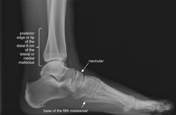
Figure 14-1 Ottawa ankle and foot rule.
Ankle x-rays are needed only if the patient has pain in the malleolar zone and any of the following is true:
Foot x-rays are needed only if the patient has pain in the midfoot zone and any of the following is true:
Box 14-1 Ottawa Ankle and Foot Rules
Adapted from Bachmann LM, Kolb E, Koller MT, et al: Accuracy of Ottawa ankle rules to exclude fractures of the ankle and mid-foot: Systematic review. BMJ 326:417, 2003.
Ankle x-ray series is required if the patient complains of pain in the malleolar zone or midfoot and has any of the following findings:
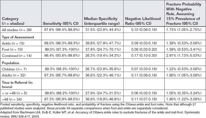
Kingdom, United States, Canada, France, Greece, Germany, Netherlands, Spain, New Zealand, Singapore, and Hong Kong), and in the hands of a variety of practitioners, including attending physicians, house officers, nurse-practitioners, and nurses. A systematic review published in the British Medical Journal in 2003 analyzed 27 studies of these rules that included 15,581 patients.151 Only 47 patients (0.3%) had a false-negative result. Results were similar in adults and children. Table 14-1 demonstrates the performance of the rule in important subgroups, including adults, children, and patients presenting within or after 48 hours of injury. Application of the rules would reduce radiography by 30% to 40%. Assuming a typical prevalence of fracture of 15%, the probability of a fracture after application of the rules is less than 2%. Although the Ottawa foot and ankle rule is one of the best-validated clinical rules in all of medicine, many emergency physicians do not use the rule appropriately, adding to their assessment factors such as swelling that have been shown to have no predictive value. In addition, only 30% of physicians correctly remember the rule, and many do not review the rule at the time of application or use memory aids.3
Ottawa Knee Rule
Stiell et al.4 found that 74% of adult patients presenting with knee injuries underwent x-ray but only 5% had fractures. From the x-rays of the knee and patella ordered, 92% were negative for fracture. The same group of investigators subsequently derived and then validated a clinical decision rule, now known as the Ottawa knee rule (Box 14-2). In a derivation set of 1047 adults, the rule was 100% sensitive (with a 95% confidence interval [CI] of 95%-100%) and 54% specific (95% CI = 51%-57%). Application of the rule would have reduced radiography from 68.6% to 49.4%, a 28% relative reduction.5 In a prospective validation study of 1096 adults, sensitivity was 100% (95% CI = 94%-100%) and the estimated relative reduction in radiography use was 28%. There was virtually no probability of fracture if the rule was “negative” (95% CI = 0%-0.4%). The rule also had excellent interobserver agreement, with a kappa of 0.77 (values greater than 0.5 are generally accepted to represent a high degree of agreement).6 A subsequent prospective study in 1522 adults showed 100% sensitivity (95% CI = 96%-100%), reductions in radiography as great as 49%, and no estimated probability of fracture with a negative rule (95% CI = 0%-0.5%).7 A systematic review found six studies, with 4249 adult patients, with high sensitivity (Table 14-2).8
TABLE 14-2 Performance of the Ottawa Knee Rule
| Performance | 95% CI | |
|---|---|---|
| Sensitivity | 98.5% | 93.2%-100% |
| Specificity | 48.6% | 43.4%-51.0% |
| Negative likelihood ratio | 0.05 | 0.02-0.23 |
From a systematic review of 4249 adult patients.
Adapted from Bachmann LM, Haberzeth S, Steurer J, ter Riet G: The accuracy of the Ottawa knee rule to rule out knee fractures: A systematic review. Ann Intern Med 140:121-124, 2004.
Limitations of the Ottawa Knee Rule: Insensitivity in Children?
One study in children suggests inadequate sensitivity of the Ottawa knee rule. In a prospective study of 234 children 18 years and younger, the rule identified 12 of 13 patients with fractures (sensitivity = 92%, 95% CI = 64%-99%), missing a nondisplaced proximal tibia fracture in an 8-year-old male.9 Other studies find the rule to be highly sensitive.9a Subsequent meta-analyses suggest sensitivity of 99% in children over the age of 5 years.9b Other authors have suggested that children be assessed using the Pittsburgh knee rule, described later. This rule in its original form mandates imaging of children younger than 12 years, although studies in patients as young as 6 years show high sensitivity.
Pittsburgh Knee Rule
Seaberg and Jackson10 retrospectively derived a clinical decision rule for knee radiography in 201 consecutive patients with knee injuries. They then prospectively validated the rule (Box 14-3) in 133 consecutive patients with knee injuries. Sensitivity was 100%, specificity was 79%, and x-ray utilization using the rule would be reduced by 78%. The same investigators prospectively compared the Ottawa and Pittsburgh rules in a sample of 934 patients, ages 6 to 96 years.9c The Pittsburgh rule was 99% sensitive (95% CI = 94%-100%) and 60% specific (95% CI = 56%-64%). The Ottawa rule was 97% sensitive (95% CI = 90%-99%) and 27% specific (95% CI = 23%-30%).
Identifying Fractures: What Do Fractures Look Like on X-ray?
Complete and displaced fractures in adults are usually overt—readily recognized by lay people, as well as nonradiologist physicians. Let’s take a moment to articulate what we are seeing when we recognize an overt fracture, because some of the same characteristics may be present in subtler fractures. In an overt fracture,
Box 14-2 Ottawa Knee Rule for Adults
Adapted from Stiell IG, Wells GA, Hoag RH, et al: Implementation of the Ottawa knee rule for the use of radiography in acute knee injuries. JAMA 278:2075-2079.
Radiography of the knee is indicated if any of the criteria are met. Sensitivity is 100%.
Adapted from Seaberg DC, Jackson R: Clinical decision rule for knee radiographs. Am J Emerg Med 12:541-543, 1994; Seaberg DC, Yealy DM, Lukens T, et al: Multicenter comparison of two clinical decision rules for the use of radiography in acute, high-risk knee injuries. Ann Emerg Med 1998;32:8-13, 1998.
the cortex of bone is disrupted and the trabecular bone is fragmented. The cortex of bone, usually a smooth continuous line on plain x-ray, is discontinuous. A line indicating the fracture connects the defect on one cortex with the cortex on the opposite side. If the fracture fragments are displaced, space divides one fragment from the other (Figure 14-2).
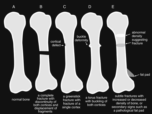
Figure 14-2 Identifying a fracture.
Some fractures are readily recognizable, whereas others are subtle or apparent only based on secondary signs of injury, rather than specific bony findings. A, Normal bone. B, Bone with an obvious complete fracture. C, Greenstick fracture, with disruption of only one cortex. D, Torus (buckle fracture). E, Subtle fractures, sometimes seen only as areas of increased or decreased density. A sail sign resulting from displacement of a fat pad by hematoma may be the only sign of an otherwise-invisible fracture.
Unfortunately, from the perspective of diagnostic simplicity, this scenario does not always occur. Let’s examine some scenarios in which fractures can be more occult.
Decreased bone density can mask cortical and trabecular abnormalities. In the case of young children, the growth plate or physis is an area of lucency, making fractures through this zone difficult to recognize—as discussed in the later section on Salter-Harris fractures. In the youngest children, entire regions of bone are not calcified, so fractures of these regions are invisible. Minimally calcified bones are flexible and may bend rather than undergo frank fracture, much like a young tree branch. In this case, one cortex undergoes compression and the opposite side experiences stretch or extension stress. The result can be a greenstick fracture, a common fracture type in children. In this fracture type, a cortical defect is seen in the side of the bone undergoing extension, whereas no fracture is typically seen in the side undergoing compression (Figures 14-3 and 14-4; see also Figure 14-2). Alternatively, the cortex undergoing compression may demonstrate another common fracture pattern, the buckle or torus fracture (Figures 14-5 and 14-6; see also Figure 14-2). These injuries typically occur with a compression injury, such as a fall on an outstretched hand (often abbreviated FOOSH) and thus are often seen in the distal forearm. The relatively soft cortex can crumple under compression rather than undergoing complete fracture, resulting in a small bump or irregularity in both cortices of a long bone. The fracture zone is sometimes visible as a lucency through the bone (see Figure 14-6). In some cases, if the compression is unequally distributed to one cortex, the typical “buckle” cortical irregularity is visible only in one cortex.
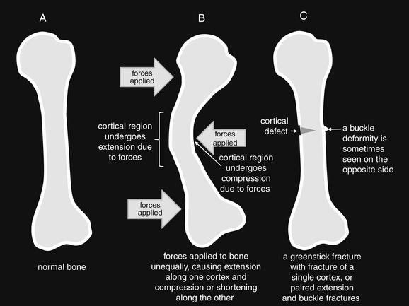
Figure 14-3 Greenstick mechanism.
Immature and partially calcified bone is soft and pliable, like a green stick from a young tree. The bone can tolerate significant bending before fracture occurs. During bending, one cortex elongates and may fracture. The other cortex shortens and may not fracture or may buckle. A, Normal bone at rest. B, Forces are applied unequally to the bone. C, Pliable bone returns to its static position, but the cortex that experienced extension has fractured, like a green stick.
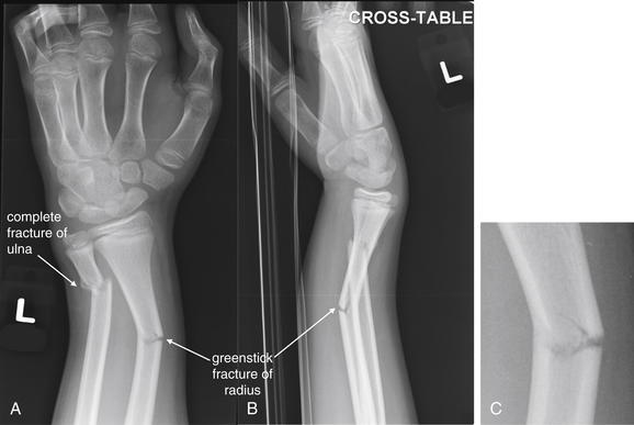
Figure 14-4 Greenstick radius fracture and complete transverse ulnar fracture.
This 11-year-old male fell on his left arm while tackling another football player. The ulna demonstrates a complete transverse fracture, whereas the radius appears to have a greenstick fracture pattern, with one cortex bending rather than showing a complete fracture. This fracture shows both dorsal and ulnar angulation. A, Anterior–posterior view. B, Lateral view. C, Close-up from A.
At the opposite extreme of age, significant osteoporosis or osteopenia can develop and complicate detection of fracture. Osteopenic bones in the elderly lack the pliable characteristics of young bones, with their flexible cartilaginous scaffolding. Instead, osteopenia contributes to brittle bones that easily fracture rather than bending. However, the paucity of calcium makes the cortex and trabecula relatively radiolucent on x-ray. Against this backdrop, the additional lucency of a cortical fracture, or injuries to trabecular bone, may be difficult to recognize. A common clinical scenario in the osteopenic patient is suspected hip fracture without clear x-ray findings. Chapter 15 discusses imaging options for this scenario in detail. Osteopenia and osteoporosis can develop in patients with chronic steroid use or who cannot bear their own weight (e.g., in nonambulatory patients with neuromuscular disease) at an earlier age.
At any age, nondisplaced fractures can be difficult to recognize on x-ray. If the fracture zone is impacted, it may appear somewhat denser than normal bone on x-ray, though a definite cortical abnormality may not be seen. Extension in the fracture zone may make this area more lucent, without a definite visible cortical abnormality. In the case of nondisplaced fractures, other secondary signs of injury may be present and can indicate the presence of fracture. A classic example is the pathologic fat pad sign of fractures about the elbow (Figure 14-7; see also Figure 14-2; this sign is also discussed later in this chapter). A fat pad is normally hidden from view on the lateral x-ray, because it is recessed in a groove of the distal humerus. When fracture occurs, a hematoma may infiltrate the groove, displacing the fat pad, which then becomes visible as a lucency called the “sail” sign on the lateral x-ray. A visible fat pad implies the presence of a hematoma, which in turn suggests a fracture. A serous joint effusion has the same radiographic appearance. Fat pads and other secondary signs of injury, such as soft-tissue swelling, are not specific for fracture. An exception is lipohemarthrosis. In the case of distal femur or proximal tibia fracture, fat and blood from the bone marrow space may enter the joint space of the knee, forming a fat–fluid level that is visible on x-ray. Although the absence of this finding does not rule out fracture, the presence of lipohemarthrosis on x-ray is highly specific for fracture.11
Some acute nondisplaced fractures are not visible on x-ray and display no secondary signs to betray their presence. When a fracture is highly suspected on clinical grounds but is invisible on x-ray, several options are available. The patient can undergo advanced imaging such as CT, MRI, or bone scan if immediate management demands a definitive diagnosis. In many cases, however, immobilization of the injured region based on the suspected injury is sufficient. Follow-up x-rays in 1 to 2 weeks may demonstrate evidence of healing fracture, such as callus formation or sclerosis, an increase in density in the fracture zone.
Describing Fractures Identified on X-ray: Standard Terminology
Fractures and dislocations identified on plain x-ray should be described using standard terminology to allow clear communication among the radiologist, emergency physician, and orthopedist or other consultant. Table 14-3 presents an algorithm for describing a fracture.
TABLE 14-3 Standard Terminology to Characterize Fractures
| Characteristic | Example |
|---|---|
| Anatomic location (including affected bone and location specified by the proximal, middle, or distal third of a long bone) | |
| Articular surface involvement | Distal humerus fracture with articular extension |
| Direction of fracture lines | |
| Distance and direction of displacement | |
| Impaction, distraction, or apposition (including bayonet apposition, in which two fracture fragments overlie one another like the blade and muzzle of a bayonet) | |
| Angulation or alignment | 20 degrees of anterior angulation |
| Severity of comminution | |
| Presence or absence of an overlying skin laceration or wound | A soft-tissue defect overlies the fracture. |
| Presence of foreign bodies or air | Radiopaque foreign bodies are present. Lucencies suggesting air are present. |
The anatomic location of a fracture should be described by naming the bone and identifying the location of the fracture within the proximal, middle, or distal third of a long bone (Figure 14-8). Extension to the articular surface of a bone should also be noted.
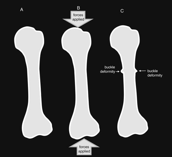
Figure 14-5 Buckle fracture mechanism.
Immature and partially calcified bone is soft and pliable. Under compression forces, the cortices may buckle rather than shattering like more heavily calcified bone. Buckle fractures can be visible along one or both cortices. The distal radius is a common location for this fracture pattern, following a fall on an outstretched hand. These fractures are typically stable as a result of impaction of the two fragments and incomplete fracturing of the cortices. A, Normal bone at rest. B, Forces are applied, compressing the pliable bone. C, Pliable cortices buckle under compressive forces. Buckle fractures can also occur with unequal application of forces to immature bone, as seen in Figure 14-3.
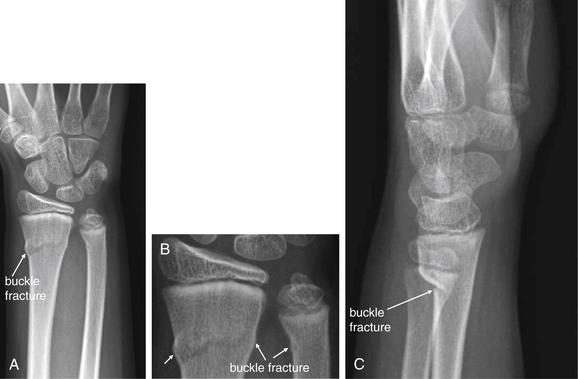
Figure 14-6 Buckle (torus) fracture of distal radius and ulna.
This 12-year-old male fell while ice-skating, landing on his outstretched left arm. Anterior–posterior (A, B) and lateral (C) views show buckle fractures of the distal radius and ulna. Buckle fractures are pediatric fractures resulting from the soft, partially mineralized cortex of immature bone. Rather than breaking completely under stress, the cortex bends or buckles, with a characteristic rounded shape.
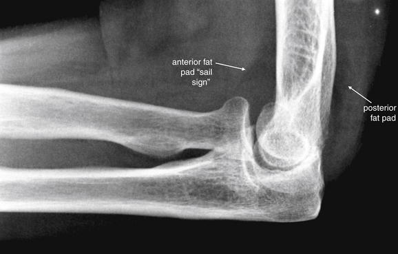
Figure 14-7 Double fat pad sign with no apparent fracture.
This 83-year-old female presented with spontaneous elbow pain without trauma. Large anterior and posterior fat pads are visible, consistent with a joint effusion displacing fat pads from their usual hidden positions. In the setting of trauma, visible fat pads suggest hemarthrosis, often associated with occult fractures about the elbow. In the absence of trauma, this finding can indicate a serous effusion or even septic joint in the correct clinical context.
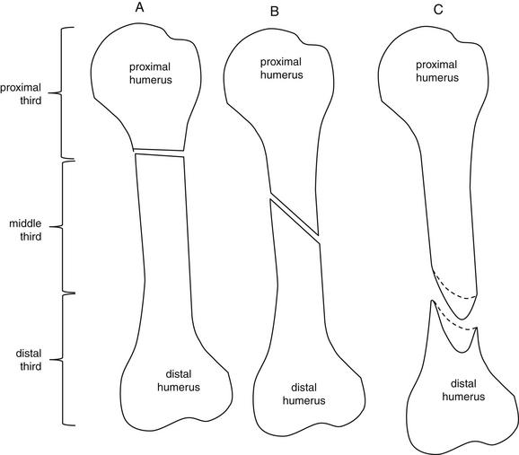
Figure 14-8 Fracture location and direction of fracture lines.
Fractures are described by naming the affected bone and identifying the position of the fracture by the proximal, middle, or distal third of a long bone. In the case of flat or irregular bones such as the scapula, a fracture may instead be described by its involvement of named structures, such as the scapular spine or glenoid fossa. The direction of a fracture relative to the long axis of the bone should be described using terms such as transverse, oblique, or spiral. If a fracture extends to an articular surface, this should be noted. A, Transverse fracture of the proximal third of the humerus. B, Oblique fracture of the middle third of the humerus. C, Spiral fracture of the distal third of the humerus. Spiral fractures result from torsion of the bone. The fracture does not lie in a single plane; rather, it creates a curved surface.
The direction of fracture lines should be described. A transverse fracture extends perpendicular to the long axis of the bone. An oblique fracture is in neither the long axis nor the short axis of the bone but rather extends in a diagonal plane. A spiral fracture extends in a helical pattern, generally along the long axis of a bone (see Figure 14-8).
A nondisplaced fracture is one in which the fracture fragments maintain their normal anatomic positions. The fracture surfaces are described as having 100% or full apposition. A displaced fracture is one in which the fracture fragments no longer are in their normal anatomic positions relative to one another. Their fractured surfaces may be in partial contact (also called apposition), or they may no longer have contact (Figure 14-9). Displacement may not be evident from a single radiograph. For example, marked displacement perpendicular to the plane of the x-ray may be undetectable. Consequently, two orthogonal-view x-rays are necessary to rule out displacement of a fracture (Figure 14-10). The distance of fracture displacement should be measured. The displacement of the distal fragment is usually described relative to the proximal fragment. Displacement can be described as AP, medial–lateral, or relative to the normal anatomic position of a limb. For example, a fragment may be described as displaced in a volar or dorsal direction, relative to the proximal fragment in the normal anatomic position. Another example of a description of a fracture fragment by anatomic relationship would be to state that a fragment is displaced in an ulnar direction, rather than describing this as medial displacement. This use of the standard anatomic position to describe fracture displacement can prevent confusion that results from less specific terms such as medial and lateral, whose meaning can vary depending on limb position.
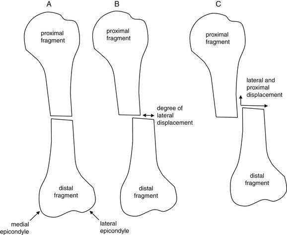
Figure 14-9 Apposition or displacement.
The distance and direction of displacement of fracture fragments should be noted. A, The proximal and distal fragments maintain their normal relationship, and no displacement is present. B, The distal fragment has moved laterally relative to the proximal fragment. Displacement is present and can be measured. C, The distal fragment has moved both laterally and proximally relative to the proximal fragment.
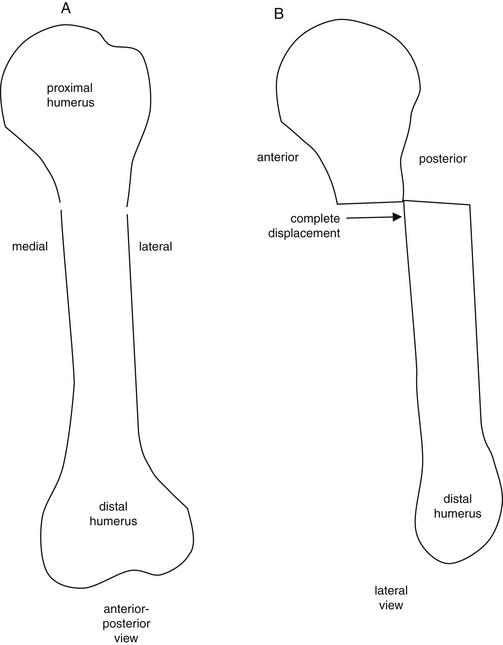
Figure 14-10 Two orthogonal views are needed to detect fracture and assess for dislocation.
A fracture line may be invisible on a single view, and displacement of a fracture may not be evident. Two orthogonal (perpendicular) views are required to minimize the risk for missing a fracture or dislocation in this way. A, In this stylized view of a humerus fracture, the fracture line is only faintly visible on the anterior–posterior (AP) view as a cortical discontinuity. No displacement is visible. B, In this lateral view, the distal fragment is seen to be fully displaced posterior relative to the proximal fragment. This gross displacement was not visible on the AP view, because the direction of displacement was perpendicular to the plane of the AP x-ray.
Impaction or distraction of the distal fragment is described relative to the proximal fragment. If the distal fragment has not moved proximally or distally relative to the proximal fragment, neither impaction nor distraction is present. If the distal fragment has moved proximally relative to the proximal fragment with the two fracture zones in direct contact because of compression, impaction is present. A distal fragment that has been proximally and medially or laterally dislocated is sometimes called an overriding fragment. If the distal fragment has moved distally relative to the proximal fragment so that a gap is present between the fracture fragments, distraction is present (Figure 14-11).
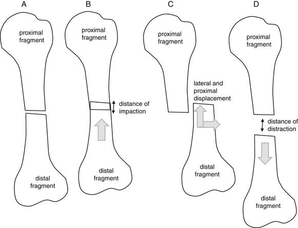
Figure 14-11 Impaction or distraction.
A, The proximal and distal fragments maintain their normal relationship, and neither impaction nor distraction is present. B, The distal fragment has moved proximally relative to the proximal fragment. Impaction is present and can be measured. C, The distal fracture fragment has been displaced both proximally and laterally and is therefore not impacted. Instead, it is described as overriding. D, The distal fragment has moved distally relative to the proximal fragment. Distraction is present. The distance of distraction can be measured.
Angulation of the distal fragment is described relative to the proximal fragment. In a long bone divided into two fracture fragments, the distal fragment is not angulated if the long axis of the distal fragment remains parallel to that of the proximal fragment. If the long axes of the two fragments are no longer parallel, the angle subtended by the two axes is the degree of angulation. Like displacement, the direction of angulation can be described in a number of ways, including AP, medial–lateral, volar–dorsal, or relative to other anatomic structures, such as adjacent bones (Figure 14-12).
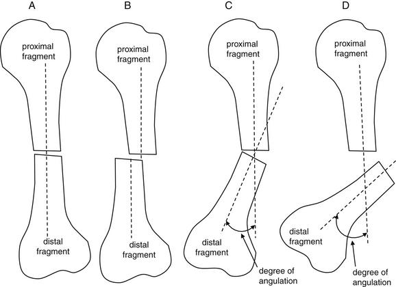
The degree of angulation of the distal fracture fragment relative to the proximal fragment should be described. A, The long axes of bone fragments remain aligned, with no angulation. B, Despite displacement of the distal fragment, the long axes of the two fragments are parallel, so no angulation is present. C, The long axes of the two fragments are no longer aligned. The angle between the two axes can be measured. D, An even greater degree of angulation is present.
Comminution describes the complexity of the fracture based on the number of fracture fragments. A simple fracture results in only two fragments and is not comminuted. A complicated fracture can result in many fracture fragments of varying size and shape and is comminuted (Figure 14-13). Other specific patterns of comminution are sometimes described. A fracture that divides a long bone into proximal, middle, and distal fragments is a segmental fracture. A fracture that results in a triangular fracture fragment, bounded by larger proximal and distal fragments, is sometimes called a butterfly fracture.
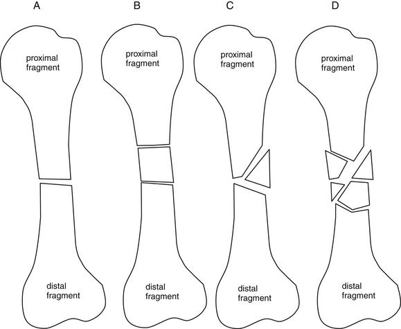
Figure 14-13 Number of fragments.
The number of fracture fragments should be described. A, The fracture has resulted in only two fragments. B, The fracture is comminuted, with three fragments. When the three fragments are arranged in this way, the pattern is sometimes called a segmental fracture. C, Another comminuted fracture. This fragmentation pattern, with a triangular fragment bounded by the proximal and distal fragments, is called a butterfly fracture. D, The fracture is severely comminuted, with multiple fragments.
Open and Closed Fractures: X-ray Findings
A fracture with no associated lacerations is a closed fracture. A fracture that communicates with an overlying laceration is an open fracture, with risk for osteomyelitis. Although the physical examination often makes this distinction evident, radiographic clues can suggest an open fracture, sometimes with the skin laceration appearing relatively remote in location on examination. Clues to an open fracture include radiopaque foreign material visible on x-ray and air within the soft tissues visible on x-ray, having entered through the wound (Figure 14-14). Although an x-ray can suggest an open fracture, it cannot rule out an open fracture, because neither air nor a foreign body may be present despite an open fracture. In addition, neither air nor a foreign body proves the presence of an open fracture. For example, air might have been introduced during local anesthetic administration. Foreign bodies might be present from a previous injury. X-ray, examination, and patient history must be correlated.
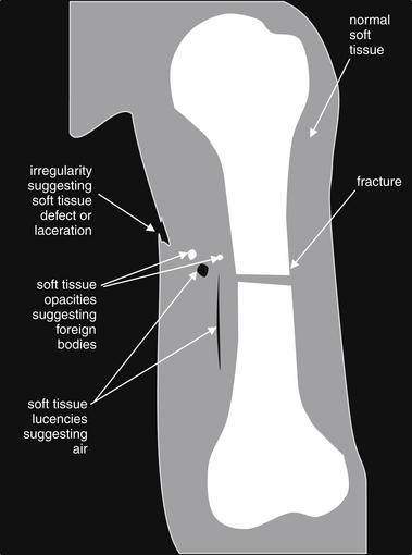
Figure 14-14 Clues to open fracture.
X-ray does not rule out open fracture, nor does it prove the presence of an open fracture. However, x-ray can yield clues to the presence of an open fracture. Air within soft tissues near a fracture suggests open fracture. Soft-tissue foreign bodies also suggest open fracture. However, an open fracture may demonstrate neither of these x-ray findings. If these findings are present, must an open fracture be present? Not necessarily. For example, air might have been introduced during local anesthetic administration. Foreign bodies might be present from a previous injury. Examination and x-ray findings should be correlated. This figure represents schematically some typical x-ray findings that may suggest open fracture. On x-ray, air outside the patient is generally black. Soft-tissue air appears nearly black as well. Soft-tissue air may track along tissue planes, giving a linear lucency appearance. A soft-tissue defect suggesting a laceration is present near the fracture. Radiopaque foreign bodies are visible, though these could represent tiny bone fragments rather than introduced foreign material.
Describing Joint Dislocations Identified on X-ray: Standard Terminology
Joint dislocations identified on x-ray can be described using terminology similar to that applied to fractures. A joint dislocation suggests complete loss of apposition of the articular surfaces of the bones comprising a joint. Joint subluxation, in which partial contact of the articulating surfaces of the bones comprising a joint is preserved, may also be seen. The involved joint should be identified and named. Dislocation is described based on the location of the distal bone, relative to the proximal bone of the joint. Dislocations can be described as medial–lateral, AP, volar–dorsal, or relative to an associated anatomic structure, such as “radially dislocated.” Associated fractures should be noted, particularly intraarticular fractures that may complicate reduction or require surgical fixation. Some fractures and dislocations are commonly seen in tandem and are discussed in later sections of this chapter; therefore when a dislocation is seen, a fracture should be considered, and vice versa. Dislocations can result in significant neurovascular injury, and normal anatomic alignment on x-ray does not rule out the presence of neurovascular injury. For example, an x-ray showing no dislocation does not exclude the possibility of a dislocation that has undergone spontaneous reduction. This is extremely important to recognize, because some dislocations pose substantial risk for vascular injury. For example, knee dislocation (not to be confused with patellar dislocation) is associated with popliteal artery injury that can result in limb ischemia, compartment syndrome, and limb loss if not recognized and treated (depicted later in this chapter). Spontaneous reduction of a dislocated knee can occur and may have no visible fractures or dislocations.
Pediatric Considerations
Salter-Harris Classification
When evaluating pediatric patients, the emergency physician must consider the possibility of injury to the growth plate, also called the physis. The physis closes at a variable age in patients of differing gender and genetic background. Before physeal closure, the physis represents a point of relative weakness. In addition, the normal lucency of the physis can prevent recognition of fractures involving the growth plate. To make matters worse, these often-occult injuries can result in arrest of bone growth; consequently, they are a source of medical–legal risk. A key point for the emergency physician bears emphasis: a normal radiograph does not rule out a physis injury in a symptomatic pediatric patient.
The Salter-Harris classification is used to characterize visible and suspected physeal injuries (Figure 14-15; Table 14-4 gives a mnemonic). Before describing this classification system, let’s briefly review the anatomy of a developmentally immature long bone. The shaft of the bone is called the diaphysis. At the proximal and distal ends of the diaphysis, the bone broadens as it approaches the growth plate, becoming the metaphysis. The metaphysis is capped by the growth plate or physis, and beyond the physis at the distal and proximal ends of the bone lies the epiphysis.
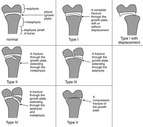
Figure 14-15 Salter-Harris fracture classification.
The Salter-Harris classification is used to describe fractures involving the growth plate. Importantly, if the clinical scenario suggests fracture (with trauma and bony tenderness), a Salter-Harris I fracture may be present, even with normal x-rays. This classification scheme is used to describe injuries in pediatric patients in whom the growth plate is not yet closed. The scheme does not apply to adult patients. Refer to this figure when reviewing the x-rays that follow.
A Salter-Harris type I fracture is a fracture through the physis, involving neither the epiphysis nor the metaphysis. Salter-Harris I fractures can occur with or without displacement. Displaced Salter-Harris I fractures are generally readily evident because of the misalignment of the epiphysis and metaphysis. The fracture itself is often not seen, because it lies through the radiographically lucent physis. Salter-Harris I fractures without displacement can be radiographically normal—with the only clinical clues to their presence being extremity pain, tenderness to palpation, and awareness on the part of the emergency physician that these injuries can be radiographically occult. Thus a normal x-ray does not rule out a Salter-Harris I fracture in a symptomatic patient. A classic example of a Salter-Harris I injury is slipped capital femoral epiphysis (SCFE), an injury demonstrated in Chapter 13.
Salter Harris type II fractures involve a fracture of the physis, extending to the metaphysis. These may occur with or without displacement. When no displacement along the physis occurs, the physeal injury itself may not be apparent but must be inferred by the visible metaphyseal fracture intersecting the growth plate. Remember that these fractures involve the metaphysis—be careful in using the terms proximal and distal to describe the extension of the fracture, because the position of the physis relative to the metaphysis is not fixed. At the proximal end of the bone, the physis is proximal to the metaphysis, so the fracture extends distally from the physis into the metaphysis. At the distal end of the bone, the physis is distal to the metaphysis, so the fracture extends proximally from the physis into the metaphysis.
Salter-Harris type III fractures extend from the physis into the epiphysis. As with type II fractures, they can be displaced or nondisplaced. Nondisplaced Salter-Harris III fractures can appear to involve only the epiphysis, but the fracture line extends to the physis—and a fracture through the physis must be inferred. Growth plate involvement is usually evident in displaced Salter-Harris III fractures, because displacement in the plane of the physis is visible.
Salter-Harris type IV fractures extend from the metaphysis, through the growth plate, and into the epiphysis. These fractures can occur with or without displacement. In some cases, the fracture line crosses directly through the growth plate, clearly connecting the epiphyseal and metaphyseal fractures. In other cases, the metaphyseal fracture line enters the physis, extends laterally in the plane of the physis, and exits at a different location into the epiphysis In these cases, the emergency physician must recognize that a type IV fracture is present and that the growth plate is involved, rather than interpreting the image as two isolated fractures without physis injury.
A Salter-Harris type V injury is a crush or compression injury of the growth plate. As with type I injuries, this injury can be radiographically occult, with a normal appearance or an appearance of modest loss of height of the normal growth plate. Consequently, a type V fracture should be specifically considered in a symptomatic patient with a normal x-ray.
Later in this chapter, figures depicting Salter-Harris fractures are labeled with icons to assist you in recognizing the fracture pattern.
Further Imaging of Pediatric Fractures: Is Computed Tomography or Magnetic Resonance Imaging Useful in Detection of Radiographically Occult Salter-Harris Injuries?
Suspected or radiographically confirmed Salter-Harris injuries are often followed today with additional advanced imaging (CT or MRI) to further characterize injuries. Such imaging provides additional diagnostic information, but it does so at a high economic cost. In addition, in the case of CT, the additional imaging results in substantial radiation exposure, an issue of increasing concern because of higher carcinogenic potential in children. The effective dose of a conventional ankle x-ray is approximately 0.01 to 0.05 mSv, whereas CT of the lower extremity results in an exposure as high as 2.7 mSv. Low-dose CT protocols have been developed to minimize radiation exposure while obtaining the additional information necessary for operative planning; one such protocol reduces the exposure to a dose range equivalent to that from plain film.12
A limitation of studies of MRI and CT in the setting of suspected injury is that no clear diagnostic reference standard is available; consequently, there is no simple method to determine whether MRI or CT findings represent true-positive, false-positive, true-negative, or false-negative results. This limitation is discussed in detail in Chapter 15.
Lemburg et al.13 compared x-ray findings against a gold standard of CT to determine the sensitivity of x-ray and to estimate the additional diagnostic yield of CT for distal tibia growth plate injuries. X-ray underestimated the presence of metaphyseal fractures, articular surface dehiscence, and intraarticular fragments. It overestimated the presence of metaphyseal and epiphyseal fractures, and it was not specific for fractures of the growth plate and articular surface. As a result of overstimulation and underestimation of metaphyseal involvement, x-ray misclassified the Salter-Harris type in 30% of fractures. The importance of misclassifications of growth plate fractures based on x-ray to therapeutic planning is less clear, though therapeutic decisions often rest on the x-ray interpretation. Prospective studies comparing therapeutic plans and patient outcomes based on x-ray alone or the addition of CT have yet to be performed.
MRI provides a radiation-free means of assessing growth plate fractures and suspected fractures. An additional advantage of MRI is that it may diagnose ligamentous injuries that may clinically simulate fracture but do not require extended immobilization. In one study of 18 suspected Salter-Harris I fractures of the distal fibula, MRI revealed no Salter-Harris fractures but instead identified 14 ligamentous injuries, 11 bony contusions, and a fibular avulsion fracture that did not involve the growth plate.14
Pediatric Patterns of Ossification
Assessment of pediatric x-rays for fracture is complicated because bones in young children are not fully ossified and large segments of bones may be invisible on x-ray. Variations in the age at which ossification occurs have been described with both gender and ethnicity. The temporal patterns of ossification are described in detail in dedicated pediatric radiology texts and are beyond the scope of this text. However, the occurrence of incomplete ossification must be borne in mind when reviewing pediatric x-rays.
Pediatric Bony Tumors and Infections
Pediatric bony tumors, including both benign conditions such as bone cysts and malignant conditions such as sarcomas, must be suspected when fractures occur in the absence of significant trauma or when bony pain occurs in the absence of trauma. Although the multitude of radiographic features that assist in distinguishing these conditions is beyond the scope of this text, some general points of distinction can be made. Benign bony tumors are usually well circumscribed, whereas malignant bony tumors may have indistinct margins. A classic finding of malignant bony tumors is periosteal reaction. A triangular appearance of new periosteal bone called the Codman triangle may occur when tumor raises the periosteum away from cortical bone. Osteosarcoma, Ewing sarcoma, and subperiosteal abscesses may all create this appearance. Periosteal reaction can also be seen as a normal finding of bone healing, usually about 3 weeks into the healing process. Osteomyelitis can also lead to periosteal reaction, so the patient history must be considered. The possibility of a malignancy or bony infection should be entertained when reviewing pediatric orthopedic x-rays. Emergency physicians frequently review orthopedic x-rays and make clinical decisions without the immediate assistance or availability of a radiologist. Losses to follow-up can create medical and legal risk when a malignant or infectious lesion is not recognized in the emergency department. When uncertainty about the nature of a bone lesion exists, careful follow-up should be arranged.
Nonaccidental Trauma
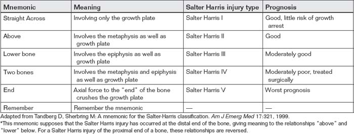
Orthopedic injuries are common in nonaccidental trauma in children, with fractures being second only to skin lesions in frequency.15 Humerus and femur fractures are the most common nonaccidental orthopedic injuries and are most frequent in children younger than 2 years.16 When reviewing pediatric orthopedic x-rays, several clues should be sought that may support or confirm the diagnosis of nonaccidental trauma. Fractures that are inconsistent with the reported mechanism of injury should raise suspicion of nonaccidental trauma (Figure 14-16). The presence of multiple healing fractures, sometimes revealed only by the presence of callus at the location of an older and incompletely healed fracture, also is concerning. Long-bone fractures in nonambulatory infants are suspicious though not pathognomonic for abuse. Corner fractures are avulsion fractures (most commonly of the distal femur and proximal tibia), which result from violent shaking of a small infant (Figure 14-17). These injuries are considered pathognomonic for nonaccidental trauma, because they do not occur with other injury mechanisms such as falls or direct blows and are rarely seen with other inherited conditions.15 Spiral fractures of extremities were once thought to be highly suspicious for nonaccidental trauma, but the link between this injury pattern and abuse has been questioned. A toddler’s fracture is a spiral fracture of the tibia that can occur during a fall in the absence of nonaccidental trauma (Figure 14-18). Unfortunately, physicians may fail to consider a nonaccidental cause of trauma in young children, potentially leaving patients susceptible to continued injury or death. Racial disparities in reporting of potential abuse exist. In one study of children younger than 3 years admitted for skull or long-bone fracture, only 22.5% of white children versus 52.9% of minority children underwent evaluation for abuse.17 Emergency physicians must consider nonaccidental trauma in every case of pediatric fracture.
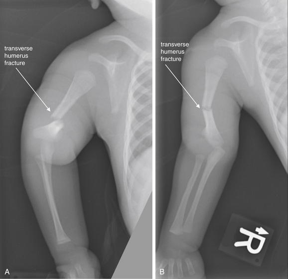
Figure 14-16 Humerus fracture from nonaccidental trauma.
This full-term 7-week-old male presented with 1 day of crying when his right arm was manipulated. The mother stated that the father had accidentally rolled onto the child while asleep the prior night. The father had reported hearing a “popping sound” and then “shook the child to make sure he was OK.” A, AP view of the upper extremity with the forearm pronated. B, AP view of the upper extremity with the forearm supinated. A complete transverse distal diaphyseal right humeral fracture is present, with anterior and medial displacement, as well as 2 mm of bony overlap. Delay in presentation after an injury and a history inconsistent with the observed injury are typical of nonaccidental trauma.
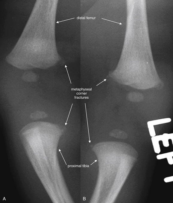
Figure 14-17 Metaphyseal corner fracture from nonaccidental trauma.
This 21-day-old male was noted by his father not to be using his right arm normally after being dressed. No history of trauma was reported. A midshaft clavicle fracture was noted on x-ray (not shown). Although clavicle fractures can result from birth trauma during vaginal delivery, this injury is not compatible with birth trauma given the patient’s age of 21 days and no evidence of healing on x-ray. A skeletal survey was performed. Close-ups from the patient’s lower extremity x-rays are shown here. A, Right distal femur and proximal tibia. B, Left distal femur and proximal tibia. Multiple lower extremity metaphyseal corner fractures are present. These involve the bilateral distal femurs and proximal tibias. Corner fractures are highly suspicious for nonaccidental trauma. When multiple injuries are present without a history of trauma, nonaccidental trauma should be suspected. Formal skeletal survey radiographs should be performed, although this may be deferred until obvious acute injuries have been stabilized.
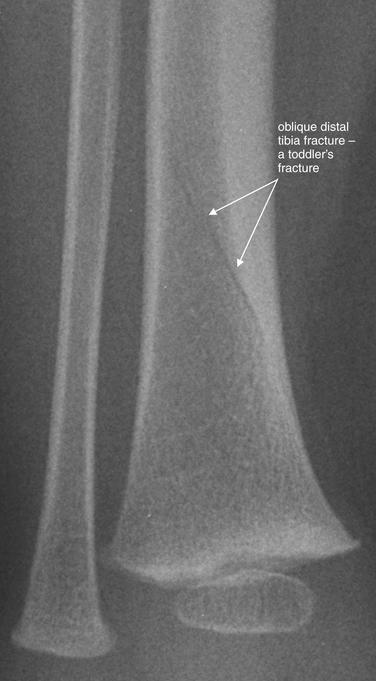
Figure 14-18 Toddler’s fracture.
This 16-month-old male fell. The patient’s mother attempted to catch him but lost her grip on his leg. He has been unable to bear weight without crying. Anterior–posterior view of the distal tibia and fibula. An oblique fracture is seen through the distal tibia, consistent with a toddler’s fracture. This injury is usually not caused by nonaccidental trauma.
Slipped Capital Femoral Epiphysis, Legg-Calvé-Perthes Disease, and Pediatric Pelvic Avulsion Fractures
Other common disorders of bone occur in skeletally immature children. SCFE is a displaced Salter-Harris I fracture of the physis of the proximal femur, occurring spontaneously in children, which can lead to avascular necrosis of the hip if not recognized and surgically treated. Legg-Calvé-Perthes disease is spontaneous avascular necrosis of the femoral head, which can lead to debilitating degenerative joint disease of the hip. A number of other avulsion fractures can occur at points of muscular attachment to the bony pelvis in young athletes, resulting from incomplete ossification. The preceding injuries are discussed and demonstrated in figures in Chapter 13.
Pathology Archive With Figures
Upper Extremity Imaging
In this section, we discuss upper extremity injuries and nontraumatic pathology, beginning with the proximal upper extremity and proceeding distally.
Scapulothoracic Dissociation
Scapulothoracic dissociation is a rare life- and limb-threatening injury because of the possibility of associated injuries to vessels such as the subclavian and axillary arteries. Neurologic injury accompanies this, with disruption of the brachial plexus or cervical nerve root avulsion. The flail extremity is consequently irreparably disabled, and amputation is commonly recommended.18-20 The scapula may appear laterally displaced on chest x-ray, and the acromioclavicular (AC) joint is often disrupted. Clavicle fracture can accompany this injury, as can other upper extremity fractures. Based on a case series of eight patients, other findings such as apicolateral pleural cap and axillary or mediastinal hematoma may be seen.21 The injury is so rare that large studies to delineate the common radiographic findings do not exist. When the injury is suspected, emergency catheter angiography or CTA should be performed and preparation made for surgery.
Clavicle Fractures
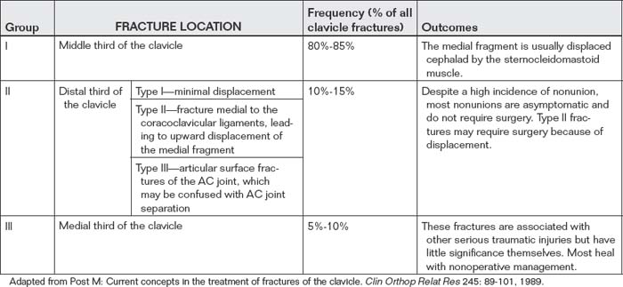
Clavicle fracture (Figures 14-19 and 14-20) is commonly seen following motor vehicle collisions and bicycling injuries. Fractures are typically classified into three groups: fractures of the middle third (group I), the distal third (group II), and the medial third (group III), as shown in Table 14-5. Fractures of the middle third of the clavicle are most common. Fractures of the distal third of the clavicle account for 10% to 15% of injuries but are usually managed nonoperatively, unless significant displacement is present. Fractures of the medial third of the clavicle are rare and are associated with significant multisystem trauma, but the fractures themselves require little management and heal without sequelae following nonoperative management.22
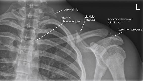
Figure 14-19 Clavicle fracture.
This 15-year-old male wrestler presented with left clavicle pain after a second wrestler fell on his left shoulder. His x-ray shows a mildly displaced midclavicular fracture with inferior displacement of the lateral fragment. The acromioclavicular (AC) joint appears intact. The sternoclavicular joint also appears normally aligned. Remember to look for clavicle fractures, sternoclavicular joint, and AC joint alignment on chest x-rays after trauma. Incidentally, this patient has vestigial cervical ribs.
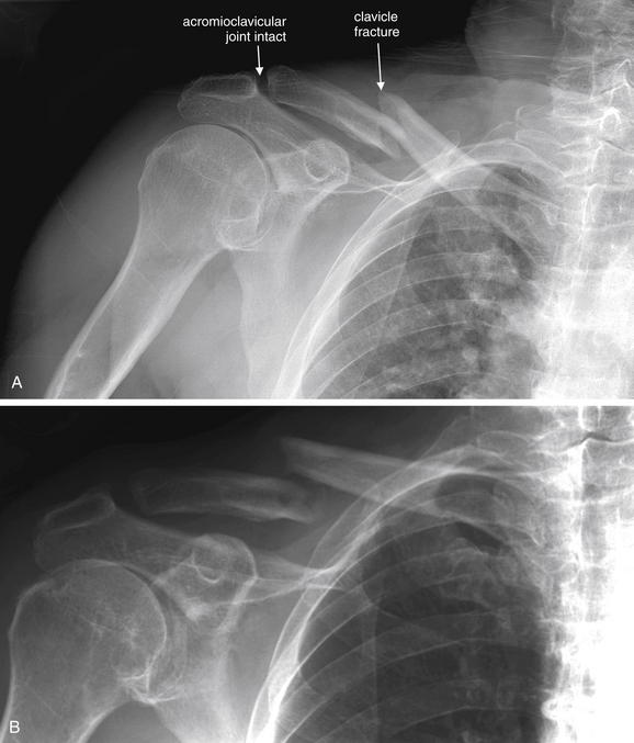
Figure 14-20 Clavicle fracture.
This 77-year-old male presented after being hit by a car on his bike. A, The patient has a fracture of the distal third of the clavicle, with displacement of the fragments. Using typical nomenclature, the distal fragment would be described as inferiorly displaced relative to the proximal fragment. In this case, the radiologist described the proximal fragment as superiorly displaced relative to the distal fragment, which communicates the same information. B, Three months later, this fracture shows minimal callus formation and demonstrates continued displacement and nonunion.
Clavicle fractures are generally not radiographically or clinically occult. A standard frontal projection chest x-ray can reveal these fractures, and the asymptomatic side provides a normal image for comparison. Evaluation should include a search for other injuries, such as pneumothorax, scapula injury, and glenohumeral joint injuries. Dedicated clavicle x-rays can be obtained that provide an AP image with the x-ray beam angled 30 degrees cephalad. A serendipity view is a supine AP x-ray with the x-ray beam angled 40 degrees cephalad to evaluate the sternoclavicular joints. Indications for surgery in clavicle fractures are based more on clinical factors than on radiographic findings. Open fractures, gross fracture displacement with skin tenting, and fractures with significant medial displacement of the shoulder girdle are managed operatively. Less serious injuries in performance athletes may be surgically repaired to speed return to play.
Acromioclavicular Joint Dislocations
AC joint dislocations (also called separations) commonly occur with mechanisms similar to those for clavicle fractures. Although the name conventionally given to these injuries is AC joint injury, a second articulation is present in the same region and may be injured simultaneously. The acromion process of the scapula is attached medially to the distal clavicle by the AC ligament. The coracoid process of the scapula lies inferior to the clavicle and is attached to the clavicle by two coracoclavicular ligaments. AC joint separations can be classified by several grading systems (Table 14-6).
TABLE 14-6 Classification of Acromioclavicular Dislocations or Separations
| Injury Grade | Description | X-ray Findings |
|---|---|---|
| I | Sprain or incomplete tear of the AC ligament | Findings are normal, without subluxation even with application of stress. |
| II | Subluxation of the AC joint with disruption of the AC ligament, but the coracoclavicular ligaments remain intact | Routine x-rays of the shoulder are normal. Subluxation of the AC joint occurs in stress views. Separation of the clavicle from the acromion process is no more than half of the clavicle diameter. The distance from the clavicle to the coracoid process is preserved. |
| III | Complete disruption of the AC and coracoclavicular ligaments, with upward displacement of the distal clavicle | Routine x-rays show widening of the AC and coracoclavicular joints. Stress views are unnecessary. |
| Rockwood Type | Description | Typical Treatment |
| I | Sprain of the joint without a complete tear of either ligament | Nonoperative management |
| II | Nonoperative management except most severe cases | |
| III | Controversial management; nonoperative management encouraged | |
| IV | Distal clavicle impaled posteriorly into the trapezial fascia | Operative management |
| V | Disruption of all ligaments with the clavicle displaced superiorly toward the base of the neck | Operative management |
| VI | Inferior dislocation of the clavicle with the lateral end displaced down | Operative management |
Adapted from Alyas F, Curtis M, Speed C, et al. MR imaging appearances of acromioclavicular joint dislocation. Radiographics 28:463-479, 2008; quiz 619.
Standard shoulder radiographs, including nonstress (non-weight-bearing) AP, axillary, and lateral projections of the shoulder, can be used if AC or glenohumeral joint injury is suspected. The normal AC joint distance in the coronal plane is variable, usually 1-3 mm, and decreases with age (Figure 14-21). An AC joint distance of more than 7 mm in men and 6 mm in women is generally considered pathologic (Figure 14-22). The normal coracoclavicular distance is 11-13 mm; an increase of 50% suggests complete AC joint dislocation.23 Stress views of the AC joint, consisting of an AP projection of the shoulder obtained with 10-15 pounds of weight attached to the arm, have been advocated to demonstrate ligamentous injury when subluxation is not evident on routine nonstress images. Normal AC joints show laxity of no more than 3 mm between the coracoid process and the clavicle with stress.24 Stress images are not necessary if subluxation is readily evident on routine images. Because management is not significantly altered in most cases by the occurrence of subluxation on stress images, it is not clear that patients benefit from this additional imaging, which can cause pain in the setting of an acute injury. If stress images are obtained, the patient should not hold the weight, because this can decrease the amount of subluxation visible radiographically because of recruitment of muscles.25 Bossart et al.26 found that weighted or “stress” x-rays only identified Grade III injuries (see Table 14-6) in 4% of cases in which the injury was not evident on routine imaging and recommended that this imaging technique be abandoned.
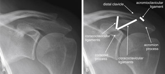
Figure 14-21 Normal acromioclavicular (AC) and coracoclavicular joints.
A normal AC joint shows close apposition of the distal clavicle and the acromion process of the scapula. These are joined by the AC ligament, which is invisible on x-ray. A second joint is also present: the corococlavicular ligament joins the coracoid process of the scapula to the distal clavicle. Injuries to these ligaments can lead to separation of these joints, as shown in Figure 14-22. A, Normal AC joint. B, Same image with the position of the AC and coracoclavicular ligaments shown.
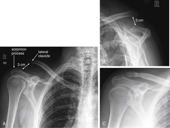
Figure 14-22 Acromioclavicular (AC) dislocation.
This 36-year-old male crashed his bicycle and was thrown over the handlebars, sustaining a Rockwood type V AC separation. Nearly 3 cm of separation is present. This was surgically repaired 2 weeks later with a hamstring tendon graft. His postoperative x-ray shows a normal AC joint. A, Anterior–posterior (AP) view. B, Lateral view. C, Postoperative AP view.
MRI can differentiate between Rockwood type II and Rockwood type III injuries when these cannot be distinguished clinically or by x-ray findings.23 However, studies suggest even type III injuries have good outcomes when managed nonoperatively, so specific diagnosis is likely unnecessary.27
Glenohumeral Joint (Shoulder) Dislocations
Glenohumeral joint dislocations are evaluated using three standard x-ray views: an AP x-ray of the shoulder, a lateral view called the scapular “Y” view, and an axillary view. It is important to recognize that dislocation can be excluded only by examining two orthogonal views. The functions of each of these views are described in Table 14-7. The normal glenohumeral joint is shown in Figure 14-23.
TABLE 14-7 Standard Radiographic Views of the Shoulder, With the Functions in Evaluation of the Glenohumeral Joint
| X-ray View | Description or Function |
|---|---|
| AP | This view allows evaluation of medial–lateral and inferior–superior dislocation of the humeral head relative to the glenoid fossa. It does not allow evaluation of AP displacement of the humeral head. It does allow evaluation of humerus, scapula, and clavicle fractures. |
| Scapular “Y” or lateral shoulder | The glenoid fossa is located at the convergence of a “Y” formed by the body of the scapula inferiorly, the scapular spine and acromion process posteriorly, and the coracoid process anteriorly. A normally located humeral head overlies this intersection. This view allows evaluation of AP displacement of the humeral head. |
| Axillary | This view confirms apposition of the humeral head and glenoid fossa articular surface. |
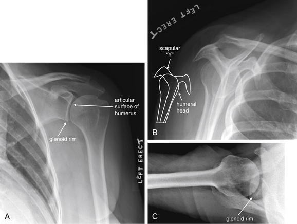
This 68-year-old female presented with shoulder pain without trauma. This x-ray shows the configuration of the normal glenohumeral joint. On the frontal projection (A), the curve of the humeral head is seated in the shallow curve of the glenoid fossa and overlaps slightly with the coracoid and acromion processes of the scapula. A scapular “Y” view (B) was obtained by aligning the x-ray beam laterally so that it is in the plane of the scapular body. This perspective places the glenoid fossa en face to the x-ray beam. The glenoid fossa lies at the center of the “Y” formed by the union of the scapular spine and acromion process posteriorly, the body of the scapula inferiorly, and the coracoid process anteriorly. A normally positioned humeral head should lie at the center of the glenoid fossa in this view. The coracoid process can be seen projecting anteriorly. In an axillary view (C), the x-ray beam is oriented up into the axilla and the humerus is slightly abducted. Again, the humeral head can be seen articulating with the surface of the glenoid fossa. In an anterior shoulder dislocation, the frontal projection usually shows medial and sometimes inferior displacement of the humeral head. The “Y” view shows the humeral head is anterior to the center of the “Y.” In a posterior dislocation (see Figure 14-24), the frontal projection occasionally appears normal, but the “Y” view shows the head is posterior to the center of the “Y.”
The most common dislocations of the glenohumeral joint (more than 90%) are anterior shoulder dislocations.28 In this injury pattern, the humeral head is typically displaced anteriorly, medially, and inferiorly relative to the glenoid fossa (Figures 14-24 and 14-25). On the AP view, the humeral head usually lies medial to the glenoid fossa, inferior to the coracoid process. It also may commonly be seen in a subglenoid position. On the AP view, the AP alignment of the humeral head with the glenoid fossa cannot be determined —so a normal appearing AP x-ray does not exclude pure anterior dislocation. On the scapular “Y” view, the humeral head is seen anterior to the center of the scapular “Y”.
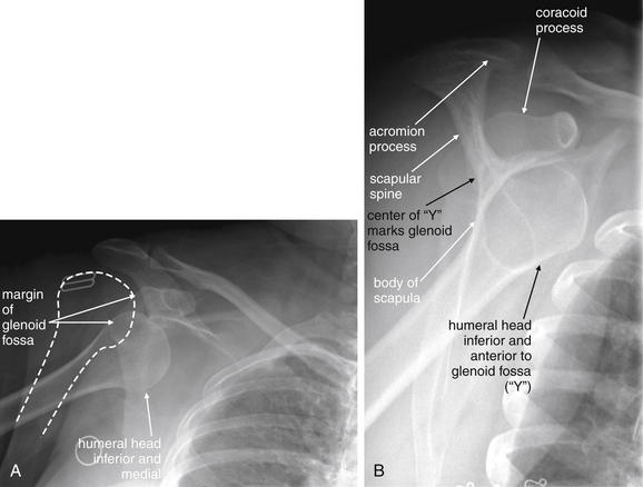
Figure 14-24 Anterior shoulder (glenohumeral joint) dislocation.
This 50-year-old female fell from standing, landing on her right shoulder. A, Anterior–posterior view. The humeral head is medially and inferiorly displaced—typical of anterior dislocation. A dashed line has been added to show the normal position of the humeral head. B, Scapular “Y” view. The humeral head is anterior to the confluence of the “Y” of the scapular body inferiorly, scapular spine and acromion process posteriorly, and coracoid process anteriorly. This “Y” marks the location of the glenoid fossa. The humeral head should be centered there.
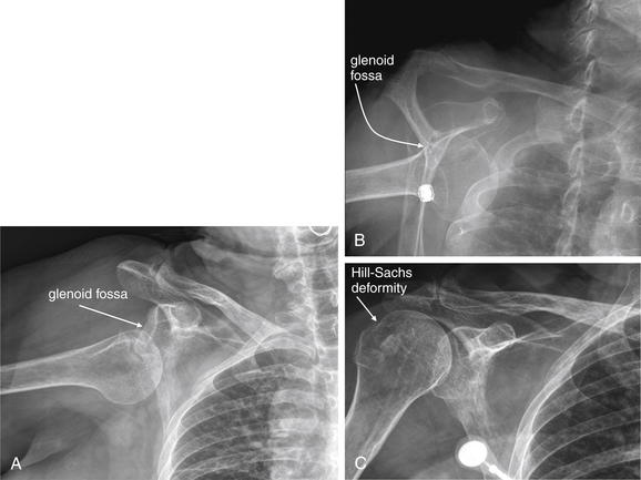
Figure 14-25 Anterior shoulder (glenohumeral joint) dislocation with Hill-Sachs deformity.
This 71-year-old female fell on her right shoulder from a standing position. Again, notice the inferior position of the humeral head relative to the glenoid fossa on the anterior–posterior (AP) view (A). In a scapular “Y” view (B), the humeral head is anterior to the “Y” marking the glenoid fossa. On the postreduction AP view (C), a cortical irregularity of the posterolateral humeral head is seen—a Hill-Sachs lesion (named for Harold Arthur Hill and Maurice David Sachs, the radiologists who described this lesion and its mechanism of injury). This is a compression deformity of the humeral head that occurs as the soft humeral head impacts against the glenoid rim during anterior shoulder dislocation. The lesion is felt to be quite specific for anterior shoulder dislocation. However, the clinical relevance is less evident. Unless large and symptomatic (causing clicking or catching of the joint), most do not require treatment.
Posterior shoulder dislocations are rarer, constituting only a few percent of all glenohumeral dislocations.28 The appearance on an AP x-ray is similar to that seen with an anterior dislocation, with the humeral head often lying inferior to the glenoid fossa. As with anterior dislocation, the AP x-ray cannot determine the AP location of the humeral head relative to the glenoid fossa, so a normal AP x-ray cannot exclude pure posterior dislocation. The scapular “Y” view confirms or excludes posterior dislocation of the humeral head (Figure 14-26). An axillary view can clarify uncertain findings on AP and “Y” views.
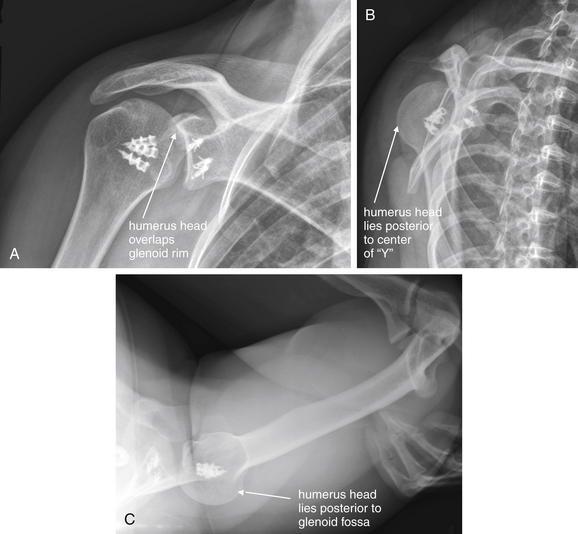
Figure 14-26 Posterior shoulder (glenohumeral joint) dislocation.
This patient has had previous reconstructive surgery, and orthopedic hardware is visible. A, Anterior–posterior view. The humeral head looks nearly normal in position, but it overlaps the glenoid rim more than usual. B, Scapular “Y” view. The humeral head is slightly posterior to the center of the “Y,” indicating posterior dislocation. C, Axillary view. The humeral head is again posteriorly subluxed.
Rarer still are inferior shoulder dislocations (luxatio erecta) and superior dislocations. Inferior dislocations are usually clinically evident because of the position of the arm, with the humerus abducted, the elbow flexed, and the hand behind or atop the patient’s head (Figure 14-27). The humeral head again appears inferior to the glenoid fossa on the AP view.
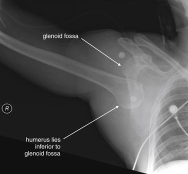
Figure 14-27 Inferior shoulder (glenohumeral joint) dislocation with luxatio erecta.
This patient presented with a classic appearance of luxatio erecta (inferior glenohumeral joint dislocation) following a motorcycle collision. The arm is abducted, and the patient’s hand was raised above his head.
Glenohumeral dislocations are frequently associated with two fractures: the Bankart lesion and
Box 14-4 Fractures Associated With Glenohumeral Joint Dislocation
Hill-Sachs deformity (Box 14-4 and Figure 14-28; see also Figure 14-25). These fractures have little immediate clinical significance. However, the Bankart fracture is associated with tears of the anterior-inferior labrum of the shoulder (visible with MRI), and thus is associated with repeated dislocation.29 MRI is considered more sensitive than x-ray30 but has no role for this indication in the emergency department. Ultrasound is also sensitive (95.6%) and specific (92.8%). CT arthrogram (using intra-articular contrast injection) can also diagnose this condition but would rarely be needed in the ED.31
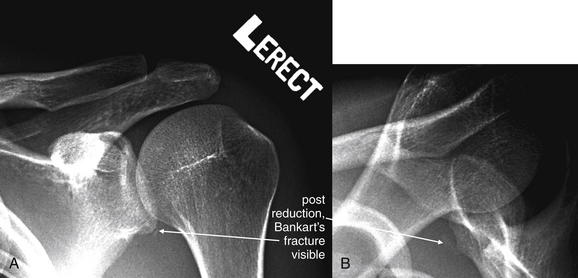
Figure 14-28 Bankart fracture.
This patient presented with his arm held in abduction and elevation, clinically appearing to be a case of luxatio erecta associated with inferior glenohumeral dislocation. His x-rays showed a more typical anterior dislocation appearance. On this postreduction x-ray, a small fragment is seen consistent with a Bankart fracture. A Bankart fracture is an avulsion of the anteroinferior glenoid labrum that usually occurs with inferior–anterior dislocation. Although subtle in appearance, the lesion is thought to be significant because it indicates stretching of the anteroinferior glenohumeral ligament, which is not visible on x-ray. Disruption of the joint capsule associated with the Bankart lesion results in continued anterior instability and a predisposition to recurrent dislocation.
Scapular Fractures
Scapula fractures (Figures 14-29 through 14-31) are classically high-energy injuries, usually caused by mechanisms such as motor vehicle collision or falls from height. They can be associated with significant multisystem trauma, including mediastinal injury, so careful interpretation of images should be performed, with attention paid to the possibility of other injuries.
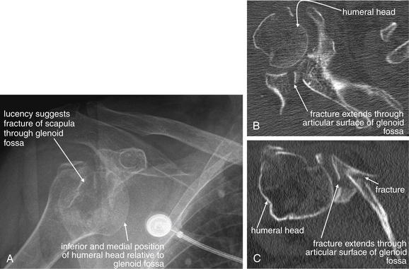
Figure 14-29 Scapular fracture with glenoid fossa involvement.
Scapula fractures are often associated with high-energy mechanisms and multisystem trauma, but sometimes relatively minor trauma can result in such injuries. This 85-year-old female fell from a standing position and complained of shoulder pain. A, Her x-ray shows anterior dislocation of the humeral head. The glenoid fossa is partially obscured behind the humerus, but a lucent area centered on the humeral head suggests a scapula fracture. CT shows a comminuted intraarticular fracture of the scapula involving the glenoid fossa. B, Axial reconstruction. C, Coronal CT reconstruction. Fractures of the scapula can be difficult to evaluate with x-ray. CT scan with multiplanar reformations can provide detailed information about the scope of scapula injury. In particular, CT provides information about intraarticular injury to the glenoid fossa, which may require surgical intervention.
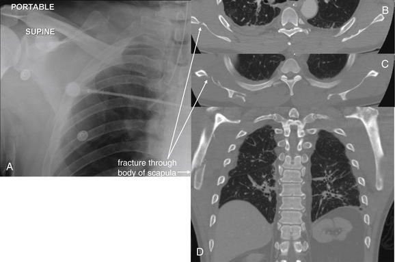
Figure 14-30 Scapular fracture.
This 56-year-old male has a scapular fracture following major trauma. His chest x-ray did not reveal this injury. He underwent pan–CT for associated injuries. His chest CT provides clear anatomic detail of his scapular fracture. He died soon after from traumatic brain injury and herniation. A, Chest x-ray. B, C, Axial chest CT images, bone window. D, Coronal reconstruction.
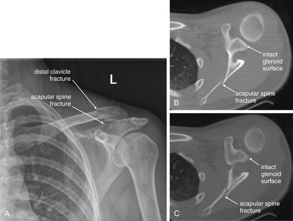
Figure 14-31 Scapula fracture.
This 19-year-old female presented after hydroplaning her car on a wet road at 60 mph, spinning the vehicle into a tree. Her sole complaint was left shoulder pain with tenderness over her left scapula and distal clavicle. A, X-ray reveals fractures of the distal clavicle and scapular spine. Avoid the error of stopping your evaluation after identifying the first fracture. B, C, Axial CT images show the fracture extends through the scapular spine and body, sparing the glenoid fossa. This injury was treated nonoperatively. Although scapular fractures in the setting of high-speed mechanisms of injury, as in this case, are associated with other major injuries, this patient had none and did well on follow-up.
A standard AP or posterior–anterior chest x-ray can reveal scapular fracture. Overlying skin folds can simulate fracture, and the medial border of the scapula can be mistaken for the pleural line of a pneumothorax (or vice versa). A standard shoulder series (described earlier) should also be obtained to allow inspection of the scapular spine, body, and glenoid fossa. CT scan is more sensitive and should be obtained when scapular injury is strongly suspected or when fractures identified on x-ray require further delineation. The scapula can be reconstructed from CT datasets acquired for evaluation of chest trauma, so additional CT imaging is generally not required if the patient has undergone chest CT. If the patient does not require CT imaging for other indications, scapular CT can be performed without intravenous (IV) contrast. Thin-section CT (1-mm to 2.5-mm slice thickness) with multiplanar reformations is useful in characterizing fractures.32-33 Haapamaki et al.33 compared x-ray and CT for the diagnosis of scapular fractures in 210 patients. Compared with CT, x-ray was insensitive in diagnosis of many fracture types (Table 14-8).
TABLE 14-8 Sensitivity of X-ray for Scapular Fracture, Compared With Diagnostic Standard of Computed Tomography
| Fracture Type | X-ray Sensitivity (CT = assumed to be 100%) |
|---|---|
| Glenoid | 88% |
| 95% | |
| 65% | |
| Acromion | 86% |
| Coracoid process | 40% |
| Scapular neck | 82% |
| Scapular wing | 94% |
| Scapular spine | 57% |
Adapted from Haapamaki VV, Kiuru MJ, Koskinen SK: Multidetector CT in shoulder fractures. Emerg Radiol 11:89-94, 2004.
Humerus Fractures
Humerus fractures are most commonly evaluated with two orthogonal x-rays: an AP and a lateral view. Fractures of the head, neck, and shaft are generally not radiographically occult, with the exception of Hill-Sachs lesions, described earlier in the section on shoulder dislocation. As we discuss later, fractures of the distal humerus can be radiographically subtle, particularly in children. These injuries can have neurovascular repercussions and are often treated operatively, so careful attention to x-ray findings and the possibility of hidden injury is essential.
Proximal Humerus Fractures (Head and Neck)
Fractures of the anatomic neck of the humerus are uncommon but can jeopardize the blood supply of the articular surface, leading to ischemic necrosis. Fractures of the surgical neck of the humerus (Figures 14-32 through 14-34), or proximal diaphyseal fractures, also threaten the blood supply of the articular surface. These injuries typically require surgical fixation if displaced or angulated, whereas less-displaced fractures are sometimes treated nonoperatively with a sling. Avulsion fractures of the greater and lesser humeral tuberosities may also be seen. Greater tuberosity fragments are often laterally and superiorly displaced, whereas lesser tuberosity fragments are usually pulled inferomedially by the attached muscles.
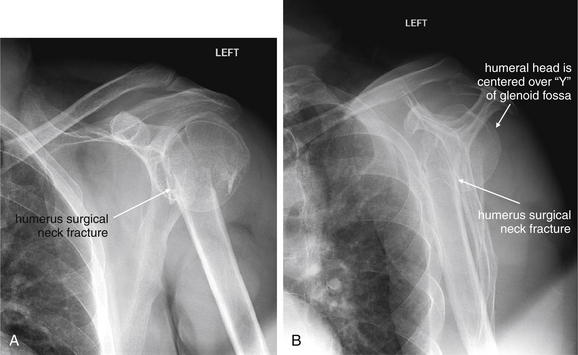
Figure 14-32 Humerus fracture (surgical neck).
This 60-year-old male presented with right shoulder pain after slipping on a wet floor and landing directly on his left shoulder. A, His anterior–posterior x-ray shows the humeral head to be appropriately located in the glenoid fossa. However, the surgical neck of the humerus shows a complete fracture through both cortices. The distal fragment is overriding the proximal fragment and is dislocated slightly medially. B, The lateral (scapular “Y”) view confirms these findings. The shaft of the humerus does not intersect the humeral head in the expected location. This injury was treated nonoperatively.
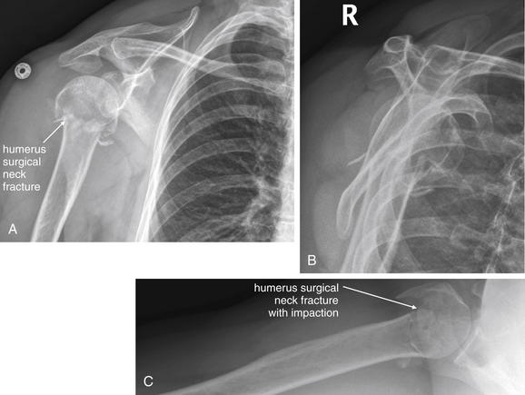
Figure 14-33 Humerus fracture (surgical neck).
This 60-year-old female presented with right shoulder pain after falling onto her right arm while intoxicated. X-ray shows a humeral neck fracture with the distal fragment impacted. The humeral head is seated in the glenoid fossa normally. A, Anterior–posterior view. B, Scapular “Y” view. C, Axillary view.
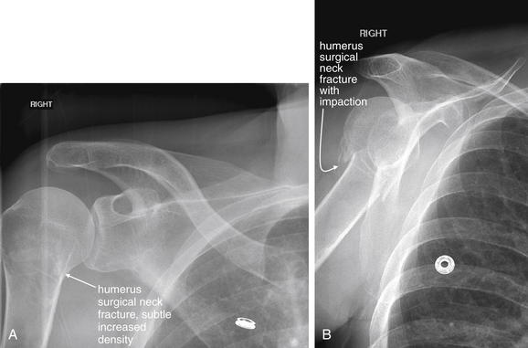
Figure 14-34 Humerus fracture (surgical neck).
This 54-year-old female fell onto her right arm. Her x-rays show the importance of obtaining appropriate orthogonal views to avoid missing a fracture. A, Anterior–posterior view. A subtle band of sclerosis is seen but might be missed—this represents the fracture zone. B, Lateral (scapular “Y”) view. A complete fracture of the humeral neck is visible, and there is impaction of the distal fragment. The overlap of the fragments accounts for the increased density seen in A.
Humeral Shaft Fractures
The humeral shaft most commonly fractures in its middle third (Figure 14-35). Neurovascular injuries can result and should be assessed on physical examination when humeral diaphyseal fractures are identified on x-ray. Brachial artery and vein and radial, median, and ulnar nerve injuries should be suspected. Nerve and vascular injury can result from the initial injury or from attempts at reduction.
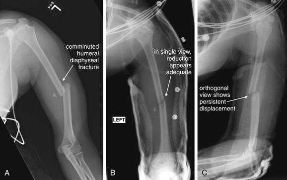
Figure 14-35 Humerus fracture (diaphyseal).
This 17-year-old female was struck by a car while crossing a road. Her x-ray shows a comminuted midshaft humerus fracture with angulation of the distal fragment. A, Only a single x-ray was obtained before reduction, so additional displacement in the perpendicular plane cannot be assessed. B, After splinting, reduction appears adequate in a single view. C, An orthogonal view demonstrates persistent fracture displacement. Two perpendicular views are needed to assess alignment in fractures and dislocations. As a rule, midshaft long-bone fractures are easily recognized, because they do not involve the overlap of other bones and normal structures such as growth plates that can make proximal and distal fractures near joints more difficult to assess.
Fractures of the Elbow
Fractures of the elbow are technically fractures of the distal humerus, proximal radius, and proximal ulna. In children, supracondylar fractures are most common (55%), followed by radial neck fractures (14%) and lateral humeral condyle fractures (12%).34 We begin our discussion with fractures of the distal humerus.
Supracondylar Humerus Fractures
Supracondylar humerus fractures (Figures 14-36 through 14-40 and 14-42) are rare in adults, accounting for only about 3% of adult fractures. In children, these fractures are more common and can be difficult to diagnose because of skeletal immaturity. Most supracondylar fractures are extension injuries, resulting from falls on outstretched arms. The distal fracture fragments are often posteriorly displaced. Displaced supracondylar humerus fractures can result in brachial artery and median, radial, and anterior interosseous nerve injury, so this fracture pattern must be recognized and associated neurovascular injuries must be investigated. Volkmann ischemic contracture can result from postfracture edema and forearm compartment syndrome. As the name implies, these injuries occur proximal to the humeral condyles and may be extraarticular. However, they often require internal fixation to prevent vascular compression and ischemia and to allow stabilization and early mobilization of the elbow. Several classification schemes have been proposed to describe supracondylar fractures, specifically with preoperative planning in mind. For emergency physicians, recognizing subtle indicators of fracture and characterizing the radiographic abnormalities by usual descriptive terms (see Table 14-3) may suffice. AP and lateral x-rays of the elbow are usually obtained to evaluate these injuries. In complex fractures, CT can assist in delineating injuries.
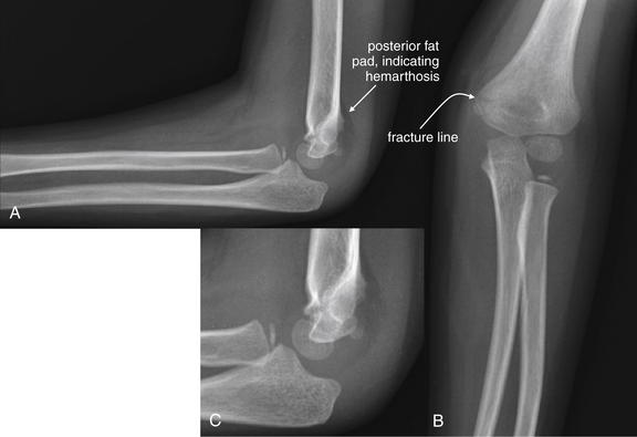
Figure 14-36 Distal humerus fracture (medial condylar fracture with pathologic fat pad sign).
This 3-year-old female fell while jumping on a trampoline and landed on her left elbow. Her x-ray shows a nondisplaced medial condylar fracture with mild dorsal angulation of the distal fracture fragment. A large posterior fat pad is visible—a sign of hemarthrosis that should alert you to possible fracture even if no fracture is seen. Fat pads are normally hidden from sight in bony grooves on the lateral view. Blood tracking in these grooves can elevate the fat pad, making it visible. An anterior fat pad can be normal, but a posterior fat pad is a pathologic sign of joint effusion or hemarthosiosis (though not always associated with fracture). A, Lateral view. B, Anterior–posterior view. C, Close-up from A.
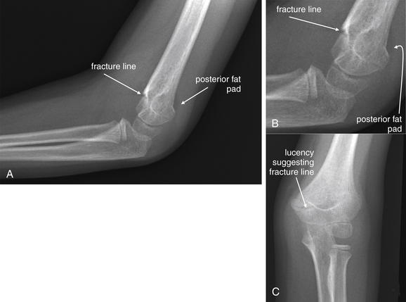
Figure 14-37 Distal humerus fracture (medial condyle).
This 5-year-old female fell while playing and complained of pain and tenderness above her elbow. As in the last case (Figure 14-36), a cortical defect is seen in the humerus, involving the medial condyle. Note the posterior fat pad, a sign of hemarthrosis often associated with fracture. A, Lateral view. B, Close-up from A. C, Anterior-posterior view.
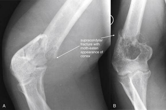
Figure 14-38 Distal humerus fracture (pathologic supracondylar fracture).
This 46-year-old male complained of severe pain in his right arm after skeet shooting. He stated that the shotgun recoiled against his right arm and that he heard a “pop” emanating from his arm. His x-ray shows an obvious fracture proximal to the humeral condyles. The history is concerning for pathologic fracture, given a modest injury mechanism. Look carefully at the lateral view (A). The proximal fragment has a thinned and irregular cortex, suggesting that a lytic lesion may have been present before the fracture. B, Anterior–posterior view. The patient underwent further workup, revealing multiple myeloma. His CT scan is reviewed in Figure 14-39.
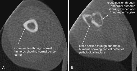
Figure 14-39 Humerus fracture (pathologic fracture with multiple myeloma), CT.
Same patient as in Figure 14-38. A, Axial section through the normal humerus proximal to the fracture zone. B, Slice through the fracture zone. In addition to the obvious cortical defect, note the moth-eaten appearance of the bony cortex compared to A. The patient was diagnosed with multiple myeloma on further workup.
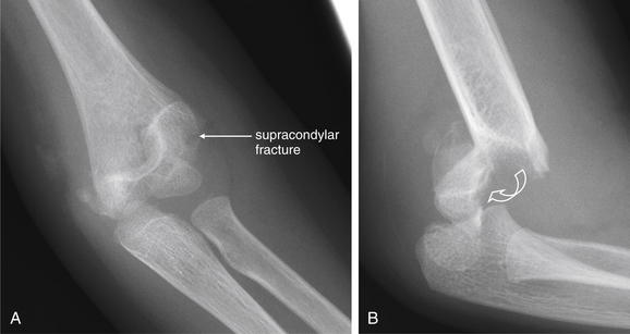
Figure 14-40 Distal humerus fracture (supracondylar fracture).
This 4-year-old female fell from a couch onto her outstretched hand, sustaining a supracondylar humeral fracture. A, An anterior–posterior view shows a fairly subtle lucency through the distal humerus. Although you may recognize this as a fracture, the degree of displacement appears minimal. In contrast, the lateral view (B) shows dramatic posterior displacement and angulation of the distal fracture fragment, emphasizing the importance of obtaining perpendicular views when evaluating for fracture or dislocation. The curved arrow is meant to convey the rotation of the fracture fragment to reach its current position. The patient underwent closed reduction and percutaneous pinning, followed by long arm cast application.
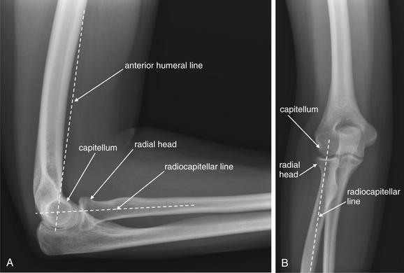
Figure 14-41 Normal alignment of radial head and capitellum.
The radial head and capitellum (the rounded portion of the distal humerus with which the radius articulates) should be aligned when no fracture or dislocation is present. On the lateral view (A), the anterior humeral line should intersect the middle third of the capitellum. Failure of this line to intersect the capitellum can occur when a supracondylar fracture is present, with posterior displacement of the distal humerus, including the capitellum. In this case, the capitellum may lie posterior to the anterior humeral line or be intersected in its anterior third. On both the lateral (A) and the anterior–posterior (B) view, a line drawn down the center of the long axis of the radius should intersect the capitellum, indicating normal radial head alignment with the capitellum. Failure of this alignment indicates radial head dislocation.
Medial Epicondylar Humerus Fractures
Fractures of the medial epicondyle are common in children between the ages of 9 and 14. Most are extraarticular, because the medial epicondyle forms an apophysis of the humerus and is not part of the articular surface. The injury can be confused with medial condyle fracture, particularly in children with incomplete ossification. An isolated medial epicondyle fracture is not associated with a positive fat pad sign, because the medial epicondyle is largely outside of the joint capsule. In contrast, a medial condyle fracture is included within the joint capsule and can result in a pathologic fat pad sign. Displacement of the epicondyle greater than 5 mm is considered an indication for surgical fixation, and functional outcomes are good with this treatment.35 Most fractures with lesser degrees of displacement are treated nonoperatively with casting, with good outcomes.36 Ulnar nerve contusion can occur with this injury. Dislocation of the elbow commonly results in epicondylar fracture.35,37
Medial Humeral Condylar Fractures
Medial humeral condyle fractures (Figure 14-43) separate the medial metaphysis and epicondyle from the remainder of the humerus. The fracture is intraarticular, involving the trochlea (the grooved surface of the distal humerus that articulates with the ulna), and thus compromises the stability of the elbow. The injury is rare and can be difficult to distinguish from medial epicondyle fracture, caused by incomplete ossification in children, the common population for this injury. When x-rays are inconclusive, arthrography,38 CT, or MRI can be diagnostic. A clue to the injury is the fat pad sign, resulting from displacement of normal fat by hematoma. A Milch type I fracture splits the trochlear groove, leaving the lateral ridge of the trochlea attached to the proximal portion of the humerus. This injury is somewhat more stable than the Milch type II fracture, which includes the entire trochlea in the distal fracture fragment and is unstable, requiring open reduction and internal fixation. These injuries are particularly serious in children because they are Salter-Harris IV injuries (by definition, involving the growth plate) and are intraarticular. Complications include growth arrest and arthritis.39
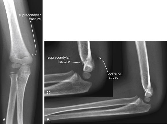
Figure 14-42 Distal humerus fracture (supracondylar fracture with fat pad).
This 4-year-old female fell onto an outstretched right upper extremity from a playhouse. Her x-ray shows a supracondylar humerus fracture. Although the fracture itself is quite evident in this case, notice the posterior fat pad, a sign of hemarthrosis. This may be your only clue to more occult supracondylar fractures. A, Anterior–posterior view. B, Lateral view. C, Close-up from B. The patient underwent closed reduction with percutaneous pinning to limit the risk for later hyperextension deformity, which could occur if the fragment becomes dorsally displaced and angulated. This fracture also poses a threat of vascular injury. Finally, the anterior humeral line does not intersect the capitellum in the expected location. This is because of mild posterior displacement and angulation of the fracture fragment. Compare this with the normal appearance in Figure 14- 41. Always assess the intersection of the anterior humeral line with the capitellum. If the normal intersection does not occur, suspect a dorsally displaced supracondylar fracture, even if the fracture line is not seen.
Lateral Humeral Condylar Fractures
Lateral humerus condylar fractures are common in young children between the ages of 5 and 10 years. They are often radiographically subtle or occult, because the distal humerus is primarily cartilage at this age. Because of this subtlety, lateral and oblique x-rays of both elbows are usually recommended to provide a normal comparison view. The typical course of the fracture line is from the lateral metaphysis proximal to the condyle, traveling distally and exiting through the articular surface in either the medial trochlear notch or the capitellotrochlear groove.40
Lateral condyle fractures can be characterized by the Milch or Jakob systems (Table 14-9).41-42 When considering the importance of lateral condyle fractures, recognize that the lateral condyle includes the capitellum and the lateral portion of the trochlea. The capitellum articulates with the radius and is thus important to forearm supination and pronation but not to elbow stability. The trochlea articulates with the ulnar and must be intact for stability of the elbow joint. Thus lateral condyle fractures that extend to the lateral trochlea can render the elbow unstable.
TABLE 14-9 Classifications of Lateral Humerus Condyle Fractures
| Milch Type | Description |
|---|---|
| I (less common) | |
| II (more common) | |
| Jakob Stage | Description |
| I | Nondisplaced, extraarticular |
| II | Intraarticular fracture, with moderate rotational displacement |
| III | Complete displacement and capitellar rotation with elbow instability |
Adapted from Milch H: Fractures and Fracture Dislocations of the Humeral Condyles. J Trauma 4:592-607, 1964; Jakob R, Fowles JV, Rang M, Kassab MT: Observations concerning fractures of the lateral humeral condyle in children. J Bone Joint Surg Br 57:430-436, 1975.
When the diagnosis is uncertain from x-ray, CT or MRI can be performed to confirm or exclude lateral humeral condyle fracture. Complications of this injury include nonunion, malunion, valgus angulation, and avascular necrosis—all potentially affecting elbow function. Fractures with greater than 2 mm of displacement are treated surgically, with percutaneous pinning or open reduction and internal fixation.40
Intercondylar Humerus Fractures
Intercondylar humerus fractures can occur in adults following major trauma or with falls on an outstretched arm. These can be complex injuries requiring surgical fixation and even total elbow replacement. Numerous classification systems have been proposed, but none fully describe all possible fracture patterns. Involvement of the articular surface should be described, noting injuries to the lateral and medial condyles.
Assessment of Injuries Involving the Trochlea and Capitellum
In addition to the preceding considerations, the trochlea and capitellum should be assessed on the lateral and AP radiographs. Subtle abnormalities in alignment may be visible, revealing an otherwise occult fracture, particularly in children with incomplete ossification. On the lateral x-ray, the anterior humeral line should intersect the middle third of the capitellum. In case of fracture, posterior angulation of the distal fracture fragment can displace the capitellum posterior to the anterior humeral line. A second line, the radiocapitellar line, is drawn down the center of the long axis of the radius and should intersect the capitellum on both AP and lateral x-rays (Figure 14-41). Displacement of the radial head, or fractures or dislocations of the capitellum (including supracondylar humerus fractures), can disrupt this normal alignment (see Figure 14-42). Fractures of the trochlea and capitellum are intraarticular and may result in a pathologic fat pad (see Figures 14-7 and 14-42).
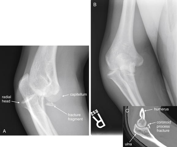
Figure 14-43 Elbow dislocation with medial condyle humerus fracture and ulnar coronoid process fracture.
This 32-year-old male was standing on a chair when he fell on his outstretched right arm, sustaining a deformity at the elbow. He was unable to flex, extend, pronate, or supinate. A, A lateral x-ray shows posterior dislocation of the radial head with respect to the capitellum. The olecranon appears posteriorly displaced with respect to the trochlea, although this image is not a true lateral but a slightly oblique view, which makes this evaluation difficult. For comparison, look at the images of the normal elbow earlier in this chapter. A bone fragment is visible distal to the distal humerus. The source is not completely clear on x-ray, although the coronoid process is a likely suspect given the apparent elbow dislocation. B, Anterior-posterior view. Again, the articular surface of the radial head is not appropriately aligned with the capitellum. After joint reduction, computed tomography confirmed a coronoid process fracture (C).
In adults, fractures about the elbow are also common following mechanisms such as falls on an outstretched arm. O’Dwyer et al.43 performed MRI in 20 consecutive patients (ages 15-71 years) with fat pad signs but no visible fracture on elbow x-ray. Fractures were detected by MRI for 75% of the patients, with 87% being radial head, 6.7% lateral epicondyle, and 6.7% olecranon. The sensitivity of the fat pad sign for occult fracture was 70% with a specificity of 80%. However, the authors noted that no change in management occurred in these patients as a consequence of this additional imaging.
Elbow Dislocations
Elbow dislocations (Figures 14-43 through 14-45) most commonly result from a fall on an outstretched arm; consequently, the most common pattern is posterior dislocation of the forearm relative to the humerus. Dislocation of the ulna from the humerus is usually accompanied by radial head dislocation. The elbow is a stable joint that requires significant force to dislocate; consequently, elbow dislocations are commonly associated with fractures, including injuries to the distal humerus, radial head, articular processes of the ulna, distal forearm, and wrist.
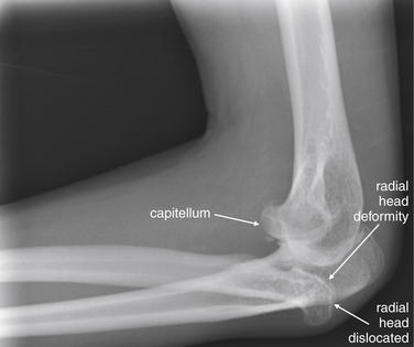
Figure 14-44 Elbow dislocation or fracture.
This 33-year-old female fell onto her left arm and noted immediate pain in her elbow. This patient has degenerative changes of the radial head, which is posteriorly dislocated relative to the capitellum. This may reflect a prior radial head fracture and dislocation. Compare with the normal alignment demonstrated in Figure 14-41.
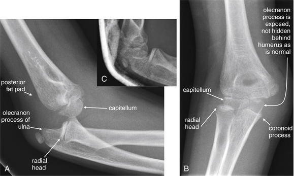
Figure 14-45 Elbow dislocation.
This 8-year-old female fell onto her elbow, hyperextending the joint. The patient complained of pain and swelling of the elbow. A, Lateral x-ray. Posterior dislocation of the elbow is evident. The anterior and posterior fat pads are visible, indicating joint effusion or hemarthrosis, although no fractures are seen. The radial head is not aligned with the capitellum. The trochlea and olecranon are not aligned. B, AP view. The radial head does not articulate normally with the capitellum, and the coronoid process of the ulna is not seated against the trochlea of the humerus. C, Postreduction x-ray. The expected normal alignment is now seen.
Nursemaid’s Elbow (Radial Head Subluxation)
Nursemaid’s elbow is subluxation of the radial head, usually seen in children between the ages of 1 and 3 years. The common mechanism of injury is traction on the arm by an adult. The patient may present with failure to use the arm, rather than overt pain. In some cases, the injury reduces spontaneously, may reduce during manipulations for physical examination, or may become reduced during x-ray. X-rays are generally not needed for the diagnosis or to confirm reduction if the patient regains normal use of the arm after reduction. However, when concern exists about other fractures or dislocations, x-rays should be obtained, including x-rays of the humerus, elbow, and forearm, depending on the examination and history.
Forearm Fractures and Dislocations
The forearm is one of the most commonly injured body regions, with mechanisms including FOOSH and defensive injuries. Injuries in this location require careful evaluation, because multiple injuries may be present from the distal humerus, to the elbow and proximal forearm, and continuing to the distal forearm and wrist. In this section, we discuss common injuries and pitfalls to be avoided.
Forearm Fractures
Radial Head Fractures and Dislocations
Radial head fractures accompany about 20% of cases of elbow fracture or dislocation, and radial head dislocation can accompany other injuries, as in the Monteggia pattern described later in this chapter. Alignment of the radiocapitellar line (described earlier) should be assessed, and the articular surface of the radius should be carefully inspected. Assessment of both AP and lateral views is essential to avoid missing radial head fracture or dislocation (Figures 14-46 and 14-47, see also Figures 14-59, 14-61, and 14-62).
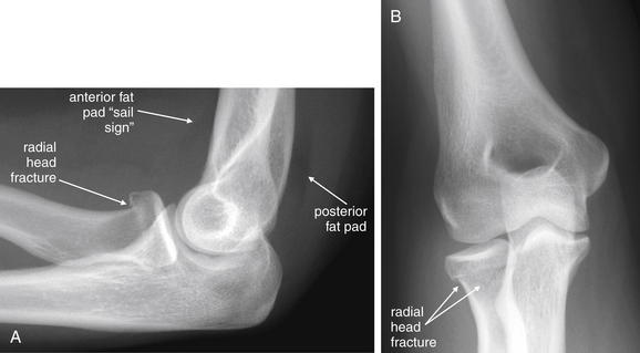
Figure 14-46 Radial head fracture and double fat pad sign.
This 28-year-old female complained of left elbow pain after falling onto her outstretched forearm. Her flexion and extension were quite limited by pain, and she was unable to supinate or pronate. Her x-ray shows a subtle fracture of the radial head. The anterior and posterior fat pads indicate a hemarthrosis associated with this fracture. Look for abnormal fat pads—and an underlying fracture when they are present. A, Lateral x-ray. B, AP view.
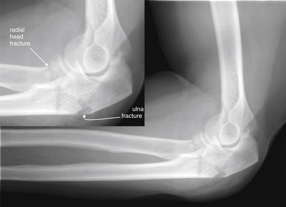
Proximal Ulna Fractures
Ulnar fractures commonly occur along the proximal third of the ulna, often in association with radial injuries, as in the Monteggia pattern described later in this chapter. The coronoid process of the ulna can be fractured during a forceful landing on an outstretched arm (Figures 14-48 and 14-49). Coronoid fractures are associated with elbow dislocation, because the distal humerus can shear the coronoid process if the ulna is dislocated posteriorly. Fractures of the olecranon can occur with FOOSH mechanisms or direct trauma.44 The fracture is usually transverse (Figures 14-50 and 14-51).
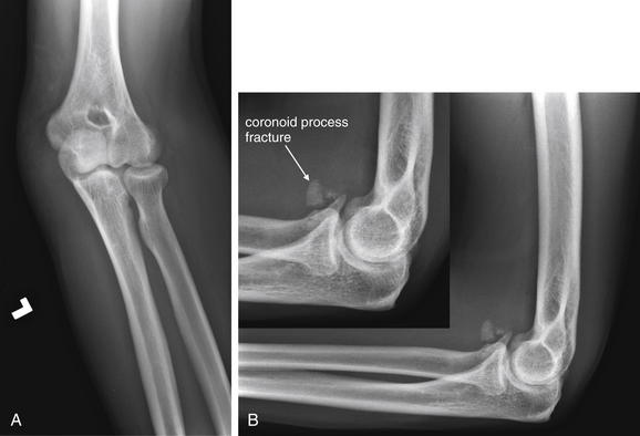
Figure 14-48 Ulnar fracture (coronoid process fracture).
This 35-year-old female fell from standing, landing directly on her left elbow. A, Anterior–posterior view, showing a normal appearing elbow with normal alignment and no visible fracture. B, Lateral view (with close-up), revealing a fracture of the coronoid process of the ulna. This fracture may appear trivial but actually undermines the stability of the elbow joint, allowing posterior subluxation of the ulna relative to the humeral condyles. The patient underwent CT (Figure 14-49), which defined this fracture in more detail.
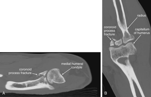
Figure 14-49 Ulnar fracture (coronoid process fracture).
Same patient as in Figure 14-48. A, Sagittal view. This CT reconstruction shows a fracture through the base of the coronoid process of the proximal ulna. Without this lip to restrict posterior motion of the ulna relative to the humeral condyle, the ulna may sublux posteriorly. B, Coronal view. The radius articulates normally with the humerus.
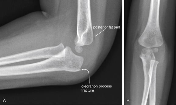
Figure 14-50 Olecranon process fracture with posterior fat pad sign.
This 2-year-old female fell on her left elbow and was not using her left arm. Her lateral x-ray (A) showed a posterior fat pad and a subtle olecranon process fracture. This was not visible on the anterior–posterior view (B).
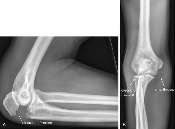
Figure 14-51 Olecranon fracture.
This 17-year-old male complained of right elbow pain after falling off his bike. The x-ray shows a proximally displaced fracture of the ulnar olecranon process, with angulation of the proximal fragment. A, Lateral view. B, Anterior–posterior view, with a large hemarthrosis visible. The olecranon fracture is also visible, though far less obvious than on the lateral image. The radial head is normally aligned with the capitellum.
Distal Radius Fractures
Distal radius fractures occur following a FOOSH mechanism. Five common patterns are described in Table 14-10. In addition to describing the fracture by these patterns, several measurements can be useful in determining orthopedic treatment. The radial height should be measured, as demonstrated in Figure 14-52. Normal radial height is 10-13 mm in adults. Radial shortening of more than 2 mm can disrupt normal wrist mechanics, leading to altered loading and osteoarthritis. Radial inclination (normal = 21-25 degrees) and volar tilt (average = 11 degrees, range = 2-20 degrees) should also be measured. Radial inclination less than 10 degrees and dorsal tilt greater than 20 degrees are associated with decreased wrist range of motion, reduced grip strength, and pain with forearm supination and pronation.45 Common radial fractures are shown in Figures 14-53 through 14-58.
TABLE 14-10 Common Distal Radius Fractures Occurring With the FOOSH Mechanism
| Name or Eponym | Description | Common X-ray Findings |
|---|---|---|
| Colles fracture | Distal radius fracture with dorsal displacement of the distal fracture fragment and wrist; occurs with a fall onto an extended wrist | |
| Smith (also called reverse Colles) fracture | Distal radius fracture with volar displacement of the distal fracture fragment and wrist; occurs with a fall onto a flexed wrist | |
| Barton fracture | Intraarticular distal radius fracture, with dislocation of the radiocarpal joint; shearing mechanism | |
| Hutchinson (chauffeur) fracture | Oblique intraarticular distal radius fracture, including the radial styloid in the distal fracture fragment; shearing mechanism | |
| Die-punch radiolunate fossa fracture | Depressed fracture of the articular surface of the distal radius, resulting from impacting of the lunate; the name die punch comes from the similarity to the depression created by a die-punch tool in a surface when struck by a hammer |
Adapted from Goldfarb CA, Yin Y, Gilula LA, et al: Wrist fractures: What the clinician wants to know. Radiology 219:11-28, 2001.
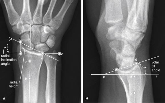
Figure 14-52 Measurement of radial height, radial inclination, and volar or doral tilt.
Several measurements assist in description of distal radial injuries. First, draw three lines on the anterior–posterior x-ray (A):
Radial height is then measured as the shortest distance from the distal tip of the radial styloid (point e) to line cd. This is line ef in the figure. A normal value is 10 to 13 mm in adults.
The radial inclination angle is the angle formed between line ed and line cd. A normal value is 21 to 25 degrees. Next, draw three lines on the lateral x-ray (B):
The angle created between line cd and line ef is the volar tilt angle, which averages 11 degrees and normally has a range of 2 to 20 degrees.
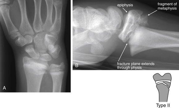
Figure 14-53 Distal radius (Colles) fracture.
This 14-year-old male fell while skateboarding, landing on his outstretched right arm. A, Anterior–posterior view. A band of increased density suggests fracture. This view does not reveal any degree of displacement. Remember that a perpendicular view may be needed to determine displacement of a fracture. B, Lateral view. The patient has a distal radial fracture, with dorsal displacement of the fracture fragment. This is consistent with the Colles fracture pattern. This fracture extends through the physis (growth plate), as well as through the distal metaphysis, making this a Salter-Harris II fracture. This was treated with closed reduction and percutaneous pinning, following by short-arm casting.
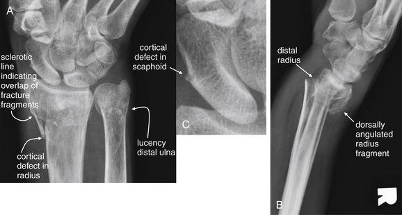
Figure 14-54 Distal radius (Colles) fracture.
This 54-year-old female fell on her outstretched right upper extremity. A, Anterior–posterior (AP) view. A cortical defect is seen in the distal radius, and a lucent band extends across the distal ulna, consistent with transverse fractures of both bones. Again, the AP view does not provide evidence of the degree of angulation or displacement. B, Lateral view. Dorsal displacement of the radial fracture fragment is seen, consistent with Colles fracture. The AP view also shows a cortical irregularity of the scaphoid, possibly indicating scaphoid fracture as well. C, Close-up.
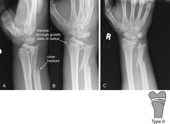
Figure 14-55 Distal radius and ulna fractures.
This 15-year-old male crashed his motorbike and sustained multiple injuries. The distal ulna is fractured, displaced, and angulated. In addition, a fracture extends through the growth plate of the radius, with dorsal angulation of the distal fragment. This is a Salter-Harris II injury. A, Lateral view. B, C, Anterior–posterior views.
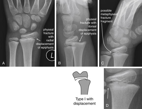
Figure 14-56 Distal radius (Colles) fracture.
This 9-year-old male fell while roller skating, landing on his outstretched hand. His x-rays show a displaced fracture through the radial physis. The dorsal displacement of the distal radius fits a Colles fracture pattern. Let’s also describe this using the Salter-Harris classification. A, Anterior–posterior view, showing radial displacement of the epiphysis. B, Lateral view, showing additional dorsal displacement of the epiphysis. C, Oblique view, showing a possible tiny metaphyseal fracture fragment. Without this additional finding, this would be a Salter-Harris I fracture. With this finding (see the close-up, D), it would be classified as a Salter-Harris II fracture. More importantly, the displacement requires reduction.
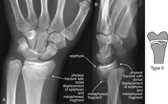
Figure 14-57 Distal radius (Colles) fracture.
This 15-year-old male fell on his outstretched left wrist 6 days prior while playing basketball. He presented with continued wrist pain. His x-rays show a transverse physeal fracture of the radius with a large metaphyseal fragment—a Salter-Harris II fracture. Given the dorsal displacement of the distal fracture fragment, this also fits a Colles fracture pattern. A, Anterior–posterior view, showing radial displacement of the fracture fragment. B, Lateral view, showing dorsal displacement. Minimal dorsal angulation is also seen.
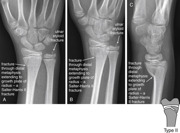
Figure 14-58 Distal radius (Smith’s) fracture.
This 12-year-old male fell from a scooter, landing prone on his outstretched right arm. He has a Salter-Harris II fracture of the distal right radius, with slight volar displacement of the distal fragment, consistent with a Smith’s fracture. An ulnar styloid fracture is also visible. A, B, Anterior–posterior views. C, Lateral view, showing the volar displacement characteristic of Smith’s fracture.
Nightstick Fractures
Nightstick fractures are isolated fractures of the ulnar diaphysis. The classic mechanism, from which the name derives, is a defensive injury sustained when the patient attempts to ward off a blow by presenting the ulnar aspect of the forearm in the path of a weapon such as a club or nightstick.
Single-Bone Forearm Fractures With Associated Dislocation of the Unfractured Bone
The close anatomic relationship of bones in the forearm results in an association between single-bone fractures and dislocations of the unfractured bone. The Monteggia and Galeazzi injury patterns (Tables 14-11 and 14-12 and Figures 14-59 through 14-62) are classic examples of this fracture–dislocation injury. The dislocations are easily overlooked because of the obvious fracture, and the emergency physician must use a disciplined approach to review the entire x-ray, rather than stopping evaluation after detection of a single injury. A common medical error is to recognize the obvious fracture while failing to identify the associated joint dislocation.
TABLE 14-11 Mnemonic for the Monteggia Fracture–Dislocation Pattern
| Say the phrase… | To remember… |
|---|---|
| Michigan | Monteggia is an |
| University | Ulnar fracture with |
| Police | Proximal |
| Department | Dislocation of the radius (radial head) |
| Pitfall | Recognizing the obvious fracture while missing the associated dislocation |
TABLE 14-12 Mnemonic for the Galeazzi Fracture–Dislocation Pattern
| Say the phrase… | To remember… |
|---|---|
| Great | Galeazzi is a |
| Rays | Radius fracture with |
| Down | Distal |
| Deep | Dislocation of the ulna (radial–ulnar joint) |
| Pitfall | Recognizing the obvious fracture while missing the associated dislocation |
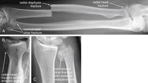
Figure 14-59 Galeazzi fracture (radius fracture with distal ulnar dislocation) variation.
This 43-year-old male was playing baseball when he slid into a base, deforming his right arm. As with many of the other cases we have reviewed, several different injuries are present—review the x-ray systematically to avoid missing injuries. A, Anterior–posterior (AP) view of forearm. B, Close-up from AP elbow. C, Close-up from AP wrist. The most obvious injury here is a transverse fracture of the distal third of the radial diaphysis. This shows ulnar displacement of the distal fracture fragment. Remember that fractures in this location are associated with dislocation of the radioulnar joint, a Galeazzi pattern of injury. A normal distal radioulnar joint should measure 2 mm. The distal radioulnar joint does appear wide in this case, and a comminuted fracture of the distal ulna is present. Also inspect the elbow for abnormal fat pads, alignment, and fracture. In this case, the patient has an intraarticular fracture of the radial head. All of these injuries were repaired with open reduction and internal fixation.
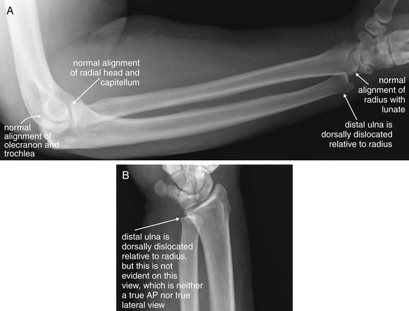
Figure 14-60 Distal radioulnar joint dislocation.
This 36-year-old male was injured when a baling machine entrapped his right forearm. He sustained a crush injury to his distal forearm and wrist. His x-rays show no fractures, but look carefully at the anterior–posterior (AP) and lateral x-rays. A, The lateral x-ray shows an abnormal position of the distal ulna. Look back at the previous forearm cases and note that a true lateral x-ray should place the radius and ulna in overlapping positions at the wrist. Instead, this patient has evidence of dorsal dislocation of the distal ulna at the radioulnar joint. Is this simply an artifact of positioning for x-ray? No, the patient’s forearm is supinated, the usual position for the lateral x-ray. The lunate bone of the wrist can be seen in its usual cup-shaped configuration, which is its appearance on a lateral x-ray in supination. The radial head articulates normally with the capitellum and the olecranon with the trochlea at the elbow. This is a case of true radioulnar dislocation. B, This view does not reveal this dislocation clearly because the dislocation is perpendicular to the x-ray plane. This image was intended to be a true AP view, but the patient was obliquely positioned at the time of image acquisition.
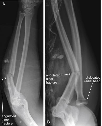
Figure 14-61 Monteggia fracture.
This 29-year-old male rolled his car over and was found walking at the scene of the collision. The patient has a classic Monteggia pattern of injury, with proximal ulnar fracture and dislocation of the radial head. The x-rays are a little confusing because neither a true anterior–posterior (AP) nor a true lateral x-ray was obtained. A, Near-AP view. The ulna appears to articulate normally with the distal humerus. The radial head is not seen well. An angulated ulnar fracture is seen, involving the proximal third of the ulna. B, Near-lateral view. The angulated ulnar fracture again draws our attention, but note the dislocation of the radial head from its normal interface with the capitellum. Whenever a proximal ulnar fracture is identified, look carefully for radial head dislocation. Inspect two perpendicular views of the elbow to avoid missing this injury. If x-rays are inadequate, insist on repeat imaging.
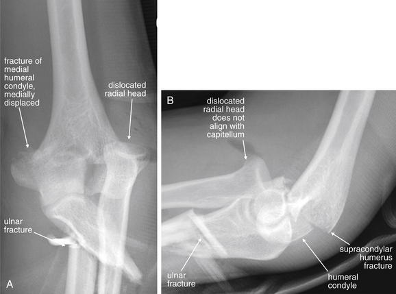
Figure 14-62 Monteggia fracture and transcondylar or supracondylar fracture of the humerus.
This 24-year-old male collided his car with a tree, sustaining a left upper extremity injury. He has a complex fracture pattern, including both a supracondylar humerus fracture and a Monteggia pattern forearm fracture. A Monteggia fracture consists of a proximal ulnar fracture with dislocation of the radial head. A, Anterior–posterior view, showing radial head dislocation, ulnar fracture, and medial condyle humerus fracture. B, Lateral view, showing the same injuries but clarifying the humerus fracture. The trochlea of the humerus remains seated in the distal ulna, which is dislocated anteriorly relative to the distal humerus.
The Galeazzi and Monteggia patterns share a common feature: one forearm bone is fractured, either proximally or distally, whereas the second forearm bone is dislocated. (see Tables 14-11 and 14-12). These injuries should be specifically considered and sought on x-ray when a forearm injury has occurred. The Galeazzi fracture–dislocation is a fracture at the junction of the middle and distal third of the radius with distal dislocation of the ulna, or distal radial–ulnar joint (see Figures 14-59 and 14-60). Conversely, the Monteggia fracture–dislocation is a fracture of the proximal third of the ulna, associated with proximal dislocation of the radial head from its articulation with the capitellum (see Figures 14-61 and 14-62).
A third example of a forearm fracture–dislocation pattern is the Essex-Lopresti fracture, a radial head fracture with dislocation of the distal radioulnar joint, resulting in disruption of the interosseous membrane.46-47 A lateral x-ray of the wrist may show subtle dorsal subluxation of the ulna (see Figure 14-60).
Carpal Bone Fractures
FOOSH mechanisms commonly result in fractures and dislocations of carpal bones. Although any carpal bone can be fractured, the most common and potentially serious fractures are those of the scaphoid bone.45 These injuries have a high rate of nonunion, resulting from the poor blood supply of the proximal scaphoid bone, which enters the proximal pole from the dorsal aspect near the waist of the scaphoid and may be disrupted by fractures through that region. This can result in avascular necrosis of the proximal pole, with persistent pain. Scaphoid fractures can be difficult to identify on initial x-rays. Evaluation of radiographically occult scaphoid injuries with MRI, CT, and bone scan is discussed in detail in Chapter 15.
The normal wrist is shown in Figure 14-63.
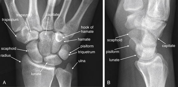
Knowledge of the normal appearance of the wrist is necessary when evaluating for wrist injuries, which can be quite subtle. Evaluate the anterior–posterior (AP; A) and lateral (B) views in all cases. On the AP view, the triquetrum and pisiform overlap. The spaces between carpal bones should be uniform on the AP view. The distal radius, lunate, capitate, and third metacarpal should align in the AP and lateral views. The alignment of the carpal bones is discussed in detail in later figures demonstrating common injuries. Refer to this figure for a normal comparison.
Scaphoid Fractures
The scaphoid bone articulates between the distal radius proximally, the trapezium and trapezoid distally, and the capitate and lunate on its ulnar border. Clinically, scaphoid fractures manifest with wrist pain, tenderness to palpation of the anatomic snuffbox, and pain with axial loading of the thumb, which transmits force to the scaphoid. On x-ray, scaphoid fractures may be obvious, with complete disruption of both cortices and displacement of fragments on AP views of the wrist. In other cases, only subtle irregularity of the cortex is visible, or no radiographic abnormality may be apparent. An AP “scaphoid view” can be obtained, with the fist clenched and the wrist held in ulnar deviation. In this position, the scaphoid assumes an elongated position and displacement of scaphoid fracture fragments is exaggerated. When fracture is not apparent on x-ray but is suspected clinically, immobilization should be performed until repeat x-rays, repeat examination, MRI, CT, or bone scan excludes or confirms fracture, as discussed in Chapter 15.
Figures 14-64, 14-66, and 14-69 demonstrate scaphoid fractures.
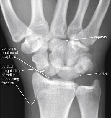
Figure 14-64 Scaphoid fracture (also distal intraarticular fracture of radius and perilunate dislocation).
This 18-year-old male was struck by a truck while riding a dirt bike. His anterior–posterior wrist x-ray shows multiple abnormalities that should immediately catch your attention. First, the spacing of the bones of the wrist is not uniform; instead, some bones overlap in unexpected ways. To recognize this abnormality, you must understand that the spacing of carpal bones is normally quite regular. Second, the proximal carpal row appears to contain five bones rather than the normal four—because of a complete fracture of the scaphoid. Third, the normal alignment of wrist bones is disturbed, without the usual alignment of lunate with capitate. In addition, the scaphoid and lunate do not have their normal separation but overlap with each other. The distal radius also shows a cortical irregularity, suggesting an intraarticular fracture. The patient’s lateral x-ray is reviewed in Figure 14-65. Computed tomography from the same patient is shown in Figure 14-66. Also compare with the normal wrist in Figure 14-63.
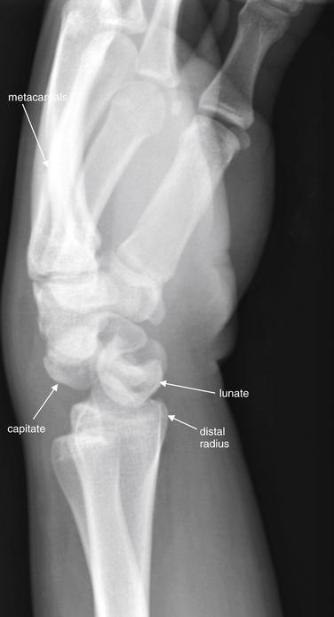
Figure 14-65 Perilunate dislocation.
Same patient as in Figure 14-64. His lateral wrist x-ray shows a perilunate dislocation. The lateral view is typically the most informative for this injury pattern. What is a perilunate dislocation? In general, think of a perilunate dislocation as a dorsal dislocation of the entire wrist and hand distal to the lunate and radius, which maintain their usual alignment. Normally, the capitate sits in the cup of the lunate, with a straight line formed by the distal radius, lunate, capitate, and metacarpal bones. In the case of a perilunate dislocation, the capitate and metacarpals “hop” as a unit out of the lunate cup, moving dorsally. The lunate remains in its normal location. This is in contrast to a lunate dislocation, in which the lunate tips in a volar direction. The usual mechanism of injury for a perilunate dislocation is a fall on an outstretched hand, with force directed dorsally through the wrist. A CT scan from the same patient is shown in Figure 14-66. Also compare with the normal wrist in Figure 14-63. Figure 14-68 compares perilunate and lunate discolorations.
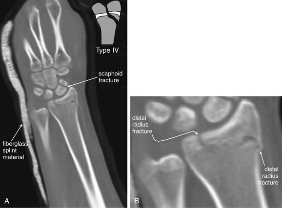
Figure 14-66 Scaphoid fracture (also distal intraarticular fracture of radius and perilunate dislocation), CT.
Same patient as Figures 14-64 and 14-65. A, Coronal reconstruction of the wrist and distal forearm. B, Enlarged view of A. The arm is intentionally positioned obliquely in the CT scanner, because this increases the number of detector lines through the region of interest, increasing sensitivity. CT is felt to be quite sensitive for bony wrist injuries using 0.625-mm slice thickness. This CT confirms a distal radius fracture involving the growth plate and epiphysis. In addition, the fracture appears to cross the physis to involve the distal metaphysis, which would make this a Salter-Harris IV fracture if it were to occur in a skeletally immature patient. In this patient, the growth plate appears closed. This CT was performed after reduction of the scaphoid fracture and perilunate dislocation described in Figures 14-64 and 14-65.
Fractures of Other Carpal Bones
Recognition of carpal fractures can be difficult for the emergency physician, resulting from the complexity of overlapping bones in the wrist. Some simple strategies can assist in recognition. First, the emergency physician should become familiar with the normal appearance of the wrist in AP and lateral views, including the normal alignment of carpal bones and their articulations with the radius, ulna, and metacarpals (see Figure 14-63). Second, true AP and lateral x-rays of the wrist should be obtained in the patient with suspected injury. Both views should be reviewed to exclude or confirm injury. The perimeter of each carpal bone should be traced, with attention to any cortical irregularity. The spacing between carpal bones should be reviewed, and any excessively narrow or wide spaces should be noted, because these can indicate injury. Figure 14-67 demonstrates triquetrum fracture.
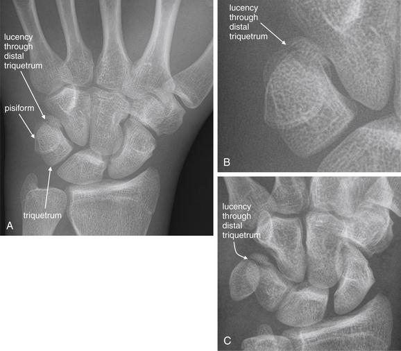
Figure 14-67 Triquetrum fracture.
This 17-year-old male fell while playing soccer, trapping his left wrist under his body. An anterior–posterior view of the wrist (A) shows normal spacing between carpal bones. The scapholunate distance is normal, and no cortical defects are seen in the scaphoid. The triquetrum and pisiform overlap as usual, but a subtle lucency is seen through the distal triquetrum—a fracture (B, close-up from A). Is CT needed to confirm this subtle abnormality? No, a slightly oblique view (C) uses parallax to move the pisiform to a nonoverlapping position, revealing the fracture in more detail.
Carpal Dislocations and Malalignments
Carpal bone dislocations and malalignments are common injuries occurring with the familiar FOOSH mechanism. We review the three most common injury patterns (Table 14-13), although other variants may be seen. Because they share the FOOSH mechanism with common fractures of the wrist and forearm, these dislocations can coexist with fractures. A common diagnostic error is recognition of either a fracture or a dislocation but failure to recognize the second injury. Figures 14-64 through 14-66 demonstrate concomitant wrist (scaphoid and radius) fractures and perilunate dislocation.
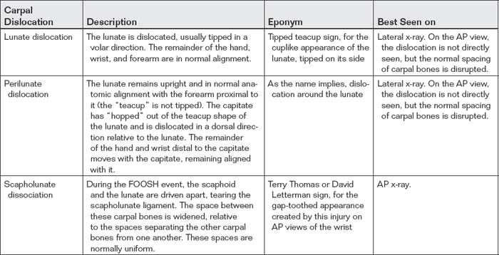
Two keys to recognition of carpal bone dislocations are an understanding of the normal alignment of these bones and a familiarity with the common patterns of dislocation. The carpal bones are arrayed in two parallel curved rows of 4 bones each, visible on the AP radiograph. The carpal bones form 3 arcs. Carpal arc I is defined as a smooth curve tracing the proximal convexities of the scaphoid, lunate, and triquetrum. Carpal arc II follows the distal concavity of these same three carpal bones. Carpal arc III is a smooth curve joining the proximal convexities of the capitate and hamate—overlapping carpal arc II. Disruption of the carpal arcs suggests fracture or dislocation. The spaces between the carpal bones are usually uniform on a true AP x-ray, measuring a few millimeters in adults. Dislocations of these bones may result in abnormal widening of the intercarpal spaces in one location and abnormal narrowing of spaces or overlap of bones in other locations. Unfortunately, if the wrist x-ray is obtained at a slight oblique angle rather than in a true AP projection, a false appearance of dislocation may result. Assessment of the plane of projection thus is an essential step in interpretation of wrist x-rays. The lateral x-ray must also be assessed, because some dislocations are most evident on this projection, as described later.
Three dislocation patterns of the wrist are most common: lunate dislocation, perilunate dislocation, and scapholunate dissociation (Figures 14-68 through 14-71). Table 14-13 compares these patterns.
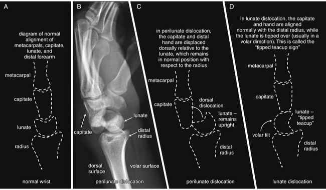
Figure 14-68 Perilunate versus lunate dislocation.
This lateral view of the wrist demonstrates a perilunate dislocation. Perilunate dislocations are characterized by translation of the capitate and bones of the hand, usually in a dorsal direction relative to the radius. The lunate remains aligned with the distal radius, whereas the capitate no longer is aligned with the radius and does not sit within the cup of the lunate. In contrast, a lunate dislocation occurs when the lunate tips on its side (the tipped teacup sign), whereas the capitate remains aligned with the distal radius. A, Normal wrist, lateral projection. B, C, Perilunate dislocation. D, Lunate dislocation.
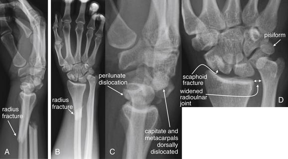
Figure 14-69 Perilunate dislocation, scaphoid fracture, and radial fracture with radioulnar dislocation (Galeazzi fracture).
This 20-year-old male fell from a tree and sustained the injuries to his right arm. His blood alcohol level was 260 mg/dL. His x-rays show several important findings. First, a radial shaft fracture is present. The fracture is transverse, with volar and proximal dislocation of the distal radius relative to the proximal fragment (lateral view, A and B). Resist the temptation to stop your assessment after identifying this injury. Look at the close-up views of the wrist from the same radiographs. On the lateral image (C), the lunate appears slightly tipped in a volar direction, which suggests lunate dislocation. However, the capitate and metacarpals are dorsally dislocated relative to the lunate while maintaining their relationship to one another. This is a perilunate dislocation. On the anterior–posterior view (D), the radioulnar joint appears wide. In combination with the radial fracture, this is a Galeazzi pattern of injury. Continue your assessment of the wrist. Count the bones of the proximal carpal row, and you will note five instead of the usual four. Two bones are located to the radial side of the lunate—actually two fragments of the scaphoid, which is fractured at its midpoint.
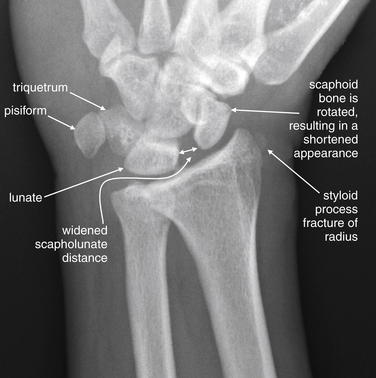
Figure 14-70 Scapholunate dislocation.
This 37-year-old male caught his arm in a grinding machine, twisting the wrist as it was drawn into the machine. Fortunately, the machine was turned off before significant crush injury occurred. On the anterior–posterior (AP) view, a styloid process radius fracture is seen with a small avulsion fragment. However, look carefully at the AP x-ray. The scapholunate interval is wide. In addition, the scaphoid bone appears shorter than usual, in this case because of volar rotation of the bone. Also, this is not a true AP view but rather a slightly oblique view. As a result, the pisiform does not appear to overlie the triquetrum. Ideally, the x-ray should be repeated to evaluate the spacing of other carpal bones, which appear to overlap because of the oblique view. Compare with additional images in Figure 14-71.
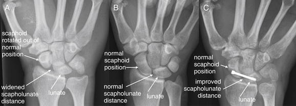
Figure 14-71 Scapholunate dissociation.
Same patient as in Figure 17-40. This 37-year-old male was working with a grinding machine when his right hand and wrist were entrapped. On emergency department arrival, diffuse swelling and tenderness of the wrist were noted. This patient has evidence of scapholunate dissociation. Findings include a widened scapholunate distance, as well as rotation of the scaphoid out of its normal position. Familiarity with the normal radiographic appearance of the wrist allows recognition of this injury. A normal wrist should demonstrate narrow and uniform spaces between all carpal bones. In addition, the normal scaphoid has a ship-like profile on an anterior–posterior (AP) view (hence its other name, navicular). A widened scapholunate distance indicates disruption of the scapholunate ligament. This gap-toothed appearance has been called the Terry Thomas sign, named for the British comedian with this famous characteristic. Scapholunate dislocation is easily missed on plain x-ray, which has a reported sensitivity of around 50%. However, a widened scapholunate distance is more than 90% specific. Posttraumatic osteoarthritis is a common result of scapholunate dissociation, so early recognition and repair is important. This patient underwent open repair of a complete scapholunate ligament tear, as well as carpal tunnel release. Despite this and additional surgical repairs of associated cartilaginous injuries, he did not regain full wrist palmar flexion or dorsiflexion. He had permanent partial loss of median nerve sensation. A, Initial AP x-ray. B, Normal wrist from another patient for comparison. C, Same patient as in A, after surgical fixation.
Lunate dislocation occurs when the lunate bone rotates out of its normal anatomic position. The lunate is named for its crescent-moon appearance, with its concave surface usually facing distally and articulating with the convex surface of the proximal capitate bone. In lunate dislocation, the lunate typically rotates 90 degrees in a volar direction, with the concave surface facing the volar wrist. On the lateral x-ray, this gives the dislocated lunate the appearance of a “tipped teacup.” The distal structures of the wrist remain in normal anatomic position.
Perilunate dislocation occurs when the capitate bone and the distal wrist and hand dislocate as a unit, usually in a dorsal direction. The capitate, which normally rests in the concavity of the distal lunate, “hops” out of the cup. The lunate retains its upright teacup appearance relative to the distal radius. This injury is seen best on the lateral x-ray. Figure 14-68 demonstrates a perilunate dislocation and compares it with a lunate dislocation.
Scapholunate dissociation occurs when a FOOSH drives apart the scaphoid and the lunate, which normally articulate with each other in the concavity of the distal radius. X-ray is relatively insensitive (57%, 95% CI = 41%-72%) but specific (98%, 95% CI = 91%-100%). Fluoroscopy can be used to assess instability at the scapholunate articulation and is more sensitive (85.7%, 95% CI = 71.5%-94.6%).48 This injury is best seen on the AP x-ray. Figures 14-70 and 14-71 demonstrate a scapholunate dissociation.
A final reminder and admonition: wrist dislocations typically occur with a FOOSH mechanism. This mechanism is also common to scaphoid bone fractures, distal radius and ulna injuries, and other extremity trauma. Beware of the temptation to cease the search for injuries once a single abnormality, such as a wrist dislocation, is identified. A comprehensive evaluation of the radiograph for other injuries is necessary. Sometimes multiple patterns of dislocation and fracture are present.
Can a Clinical Decision Rule Reduce Radiography Following Pediatric Wrist Trauma?
Earlier in this chapter, we discussed clinical decision rules, including well-validated rules for imaging of knee, ankle, and foot injuries. Studies of indications for wrist radiography are more limited. Webster et al.49 prospectively evaluated criteria for wrist radiography in 227 children. A rule incorporating radial tenderness, focal swelling, and abnormal supination or pronation of the forearm had sensitivity of 99.1% but specificity of only 24%, with a resulting radiography rate of 87% compared with standard practice in this study. This rule has not been externally validated, and more work is needed to identify clinical factors that exclude fracture and eliminate the need for imaging.
Metacarpal Fractures
Metacarpal fractures can occur with a variety of mechanisms, including offensive and defensive postures by the patient. Clinically important injuries include the boxer’s fracture; extraarticular fractures of the base, shaft, and neck; and intraarticular fractures. Metacarpals are conventionally numbered one through five, beginning with the thumb and ending with the small finger.
Boxer’s (Fighter’s) Fractures
A boxer’s or fighter’s fracture (Figures 14-72 through 14-74) occurs with a clenched fist striking an immobile object, often a wall or another person. The fracture usually involves the neck of the fifth or sometimes fourth metacarpal. Open fractures in this location are common, and air and foreign bodies such as teeth may be seen on x-ray—resulting from punching an opponent’s mouth. Infection of such open injuries is common and has gained a specific name, the “fight bite” or “clenched fist” injury. Boxer’s fractures should be assessed for air and foreign bodies, degree of angulation, and rotational deformity (see Figure 14-74). Typically, the metacarpal head is angulated in a volar direction, as measured using the lateral radiograph. The normal angle of the metacarpal neck is 15 degrees. Angulation greater than 30 degrees interferes with fist closure or flexion at the metacarpophalangeal (MCP) joint, giving a “clawed” appearance and resulting in functional impairment of flexion caused by shortening of intrinsic muscles of the hand.50 If closed reduction cannot decrease angulation below this threshold, percutaneous fixation may be required.
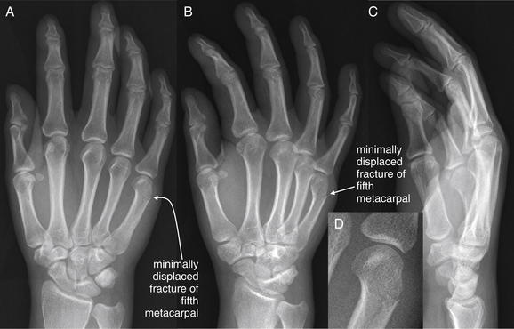
Figure 14-72 Boxer’s fracture.
This 23-year-old female sustained a hand injury in a motor vehicle collision. Her x-rays show a minimally displaced fracture of the distal fifth metacarpal, without intraarticular extension. The injury fits a boxer’s fracture pattern, although her mechanism of injury is not typical. The anterior–posterior (A) and oblique (B) views demonstrate this injury clearly, though it is not clearly seen on the lateral view (C). Minimal angulation is present, and splinting without further reduction would have an acceptable outcome. Importantly, no rotational deformity is evident, because this would require reduction. D, Close-up from A.
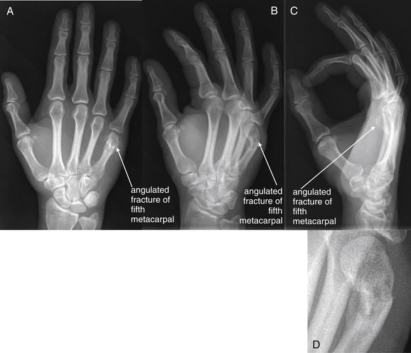
Figure 14-73 Boxer’s fracture (fifth metacarpal neck fracture).
This 39-year-old male complained of hand pain after dropping a brake rotor on his hand. His x-rays show a volar angulated fracture of the distal fifth metacarpal. The anterior–posterior (AP) view (A) may appear confusing—a cortical break is not definitely seen, although the fifth metacarpal head appears abnormally positioned. The fifth metacarpal seems short. On the oblique view (B), both the cortical defect and the degree of angulation are evident. The lateral view (C) shows the fifth metacarpal head to be tilted in a volar direction and projecting anterior to the other distal metacarpals. D, Close-up from B. Reduction of this injury is necessary because it exceeds 30 degrees of angulation on the lateral view. Normally, the angle between the neck and the head of the metacarpal is 15 degrees on the lateral view. Measurement of this angle is shown in Figure 14-74. No lateral angulation on the AP view should be accepted, nor should a rotational deformity, because these will lead to the patient’s fifth finger crossing the others when flexed at the metacarpophalangeal joint. If the fracture is not reduced, range of motion at the metacarpophalangeal joint will be impaired. Did the patient report the true mechanism of injury? This is a boxer’s fracture, with the most common mechanism being blunt trauma from punching a hard object with a clenched fist.
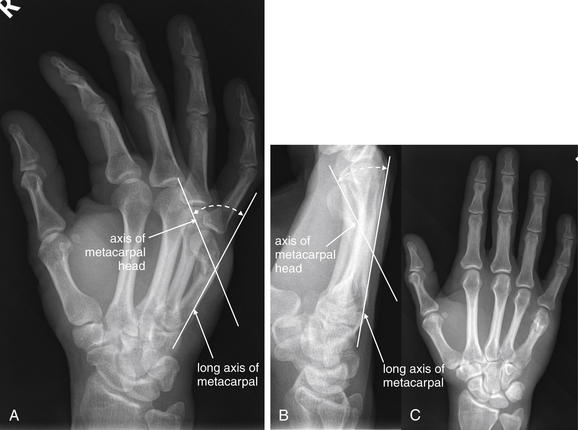
Figure 14-74 Boxer’s fracture, measurement of angulation.
Normal angulation of the distal metacarpal head relative to the long axis of the metacarpal is 15 degrees. Angulation greater than 30 degrees results in functional deficits of flexion at the metacarpophalangeal joint and should be reduced. A, Oblique view. B, Lateral view. C, AP view.
Rotational deformity along the long axis of the metacarpal results in an MCP joint that is rotated off-axis with respect to the other MCP joints. Consequently, when the affected joint is flexed, the affected finger crosses other fingers, interfering with normal grip. Any degree of malalignment on AP x-ray of the hand suggests an axial or rotational deformity. Intraarticular fractures of the metacarpal head require operative management.
A Bennett fracture is an oblique intraarticular fracture at the base of the first metacarpal (metacarpal of the thumb), extending into the carpometacarpal joint. Subluxation or dislocation of the carpometacarpal joint may also be seen. The proximal fracture fragment is typically small but includes the insertion site of the anterior oblique ligament, which typically maintains the fragment in its normal anatomic position. The distal fracture fragment includes the majority of the metacarpal bone, including most of the proximal articular surface. This fragment is typically subluxed from its normal anatomic position by the actions of the abductor pollicis longus and adductor pollicis muscles. The trapeziometacarpal joint is unstable with this fracture and requires immobilization: thumb spica casting when subluxation of less than 1 mm is present, percutaneous pinning for subluxation of 1 to 3 mm, and open fixation for subluxation greater than 3 mm. Failure to diagnose and treat appropriately can lead to posttraumatic arthritis and pain, which are common sequelae even with treatment. Normal, painless thumb range of motion is critical to hand function, making deficits resulting from Bennett fractures particularly disabling.51-52 Figure 14-75 demonstrates a Bennett fracture.
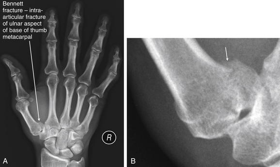
Figure 14-75 Bennett fracture of the right thumb (proximal thumb metacarpal fracture with intraarticular extension).
This 45-year-old male was a restrained driver in a rollover motor vehicle collision. He complained of pain with movement of his right thumb. A, His anterior–posterior x-ray shows a fracture at the base of the right thumb metacarpal, with 2-mm displacement. This extends to the carpometacarpal joint on the ulnar side. The lateral x-ray did not reveal the fracture. B, Close-up. An intraarticular fracture in this location is called a Bennett fracture. The most common of thumb fractures, it involves a proximal metacarpal fragment that remains attached to the palmar beak ligament (also called deep anterior oblique ligament). This keeps the proximal metacarpal fragment in normal anatomic position, while the distal fragment is often dislocated by the action of its attached muscles. Repair is required to maintain stability and mobility of the thumb.
A Rolando fracture is a comminuted intraarticular fracture of the base of the first metacarpal. The fracture has three fragments, with a characteristic “T ” or “Y” shape. The two proximal fracture fragments involve the articular surface with the trapezium. The distal fracture fragment is largest and consists of the remainder of the metacarpal. Rarer than Bennett fracture, this injury has a worse prognosis. Operative fixation is required to restore the articular surface.53 Figure 14-76 demonstrates a Rolando fracture.
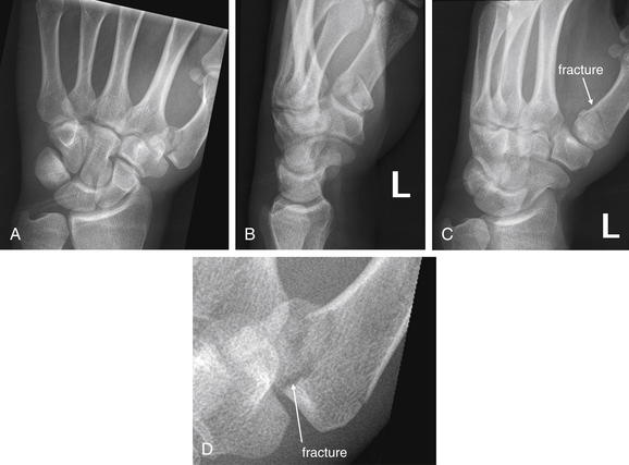
Figure 14-76 Rolando or Bennett fracture?
This 23-year-old male was a pedestrian struck by a police car. X-rays of his left wrist show a comminuted fracture of the base of first metacarpal, which extends intraarticularly. From these images, it is difficult to distinguish this injury from a Bennett fracture, which is not comminuted. The radiologist characterized this as a Rolando fracture; the orthopedist called it a Bennett fracture. Because of the minimal degree of displacement, the patient was treated with thumb spica splinting with good results. A, Anterior–posterior view. B, Lateral view. C, Oblique view. D, Close-up from A.
Figures 14-77 and 14-78 demonstrate other metacarpal fractures.
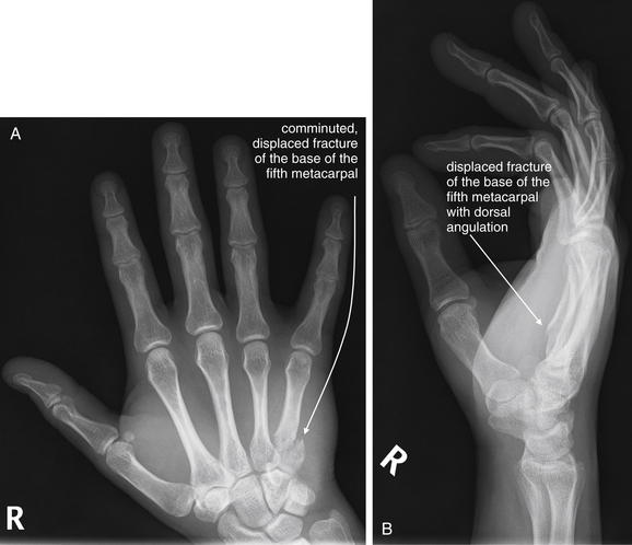
Figure 14-77 Displaced, comminuted fracture of base of fifth metacarpal.
This 26-year-old male fell from a skateboard the previous evening and complained of pain and swelling in the ulnar aspect of his right hand. A, Anterior–posterior view, showing a comminuted, displaced fracture of the base of the fifth metacarpal. This does not appear to extend intraarticularly. B, Lateral view, also demonstrating some dorsal angulation of the fracture. This injury was treated with open reduction and internal fixation.
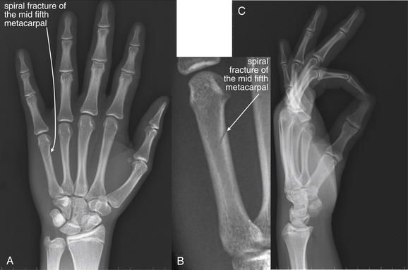
Figure 14-78 Nondisplaced spiral fracture of the middle third of the fifth metacarpal.
This 16-year-old male blocked a blow from a piece of lumber using the ulnar aspect of his hand. He has a subtle spiral fracture of the fifth metacarpal without displacement, visible on the anterior–posterior view (A; B, close-up) but not on the lateral view (C).
Fractures at other locations along the course of metacarpals are possible but more rarely pose diagnostic or therapeutic dilemmas.
Phalangeal Fractures and Dislocations
Phalangeal fractures and dislocations are common, resulting from the constant exposure of hands to potential trauma. Simple dislocations of interphalangeal joints are radiographically obvious (Figure 14-79), although associated ligamentous injuries may be present and are not visible on plain radiographs. Follow-up radiographs can demonstrate the development of deformities resulting from untreated ligamentous injury (Figure 14-80). Intraarticular fractures may occur with or without dislocations (Figure 14-81; see also Figure 14-145 later in the chapter). Following reduction of a dorsal or lateral dislocation of the proximal interphalangeal (PIP) joint, the joint is usually splinted in 10 to 30 degrees of extension to prevent additional volar plate injury.
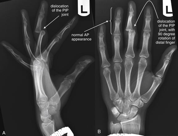
Figure 14-79 Dislocation proximal interphalangeal (PIP) joint.
This 26-year-old female fell while dancing at a nightclub, injuring her left hand. There is a dislocation at the level of the third PIP joint. The middle phalanx is dislocated a complete shaft width dorsally and a half shaft width in the ulnar direction. In both A and B, the middle and distal phalanx of the involved finger have a different profile from the other digits—this is caused by rotation of the middle phalanx relative to the proximal phalanx by nearly 90 degrees. As a result, the distal finger appears to have a lateral configuration on the AP view and an AP configuration on the lateral view. The dislocation was reduced, but on follow-up 3 months later the patient was noted to have a marked boutonniere deformity of the left middle finger, consistent with central slip injury (Figure 14-80). Interphalangeal dislocations warrant orthopedic follow-up because of the possibility of ligamentous injuries not directly visible on x-ray. A, Lateral view. B, Anterior–posterior (AP) view.
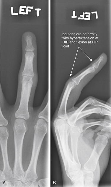
Figure 14-80 Dislocation proximal interphalangeal (PIP) joint with subtle boutonniere deformity.
Same patient as Figure 14-79. In these 3-month follow-up x-rays, a boutonniere deformity of the left middle finger is visible, consistent with central slip injury. This injury is visible on the lateral (B) but not on anterior–posterior (A) view. DIP, Distal interphalangeal.
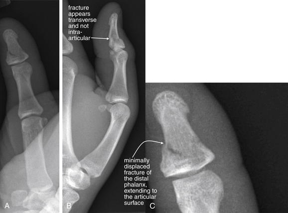
Figure 14-81 Intraarticular phalangeal fracture.
This 18-year-old male complained of left thumb pain after falling off of his dirt bike and jamming his thumb into the ground. A, Anterior–posterior view. A minimally displaced fracture of the distal phalanx is seen, extending to the articular surface (see close-up, C). B, Lateral view. This fracture is not seen to involve the joint. Two perpendicular views are necessary to evaluate fracture displacement, angulation, dislocation, and potential articular involvement.
Boutonniere deformities are characterized by flexion at the PIP joint and hyperextension at the distal interphalangeal (DIP) joint. These deformities may occur after volar dislocations of the PIP joint, closed injuries with axial loading (“jammed finger”), or forced flexion of the PIP with the PIP in extension. The mechanism resulting in boutonniere deformity is disruption of the central slip, a structure of the extensor hood of the finger. An intact central slip maintains the lateral bands of the extensor hood in a location dorsal to the axis of rotation of the PIP. Once the central slip is disrupted, the lateral bands migrate volar to the axis of rotation of the PIP, forcing it into flexion and causing extension of the DIP. Patients with volar dislocations of the PIP and even radiographically normal fingers with a “jamming” mechanism should be warned of the possibility of this deformity and advised to follow-up. Extension splinting of the PIP joint is usually performed.54
Mallet deformity occurs with stretch of the extensor tendon of the finger or its avulsion from the distal phalanx. Forced flexion of an extended DIP joint can result in this injury. The injury is usually delayed in presentation, but injuries to the DIP joint, including axial loading injuries, distal phalanx fractures, intraarticular fractures, and dislocation or volar subluxation of the distal phalanx should raise suspicion of this injury. Bony mallet injuries include avulsion of the proximal articular surface, whereas ligamentous mallet injuries have no visible fracture. Large avulsion articular fragments may be associated with the development of mallet deformity, according to a cadaver model.55
Transverse fractures of phalanges are common (Figure 14-82), as are tuft fractures. Tuft fractures (Figure 14-83) are fractures of the distal tip of the distal phalanx, usually because of a crush mechanism. These injuries may be open or closed. Finger amputations are clinically obvious but are usually evaluated with x-ray for foreign body and to delineate fractures (Figure 14-84).
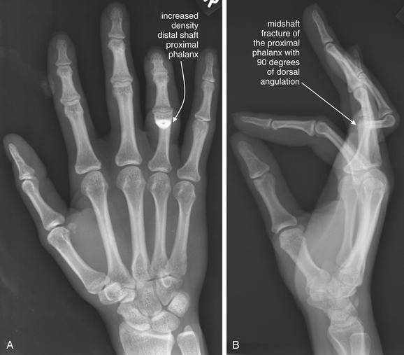
Figure 14-82 Transverse fracture of fourth proximal phalanx.
This 28-year-old female was struck on her right ring finger with a hammer. A, Anterior–posterior x-ray, showing a high-density area of the distal shaft of the fourth proximal phalanx. Is this increased density a ring on the finger? No fracture or dislocation is seen in this view although the fourth proximal phalanx appears rather short. In stark contrast, the lateral view (B) reveals the area of increased density to be caused by a middiaphyseal fracture that is angulated dorsally by 90 degrees. This case illustrates the key importance of obtaining two orthogonal views when assessing for fracture or dislocation.
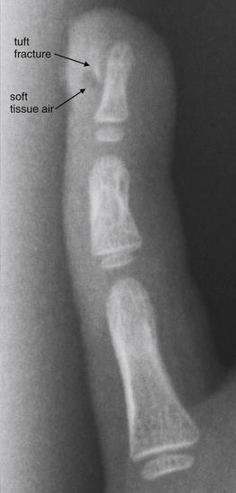
This 3-year-old female closed her left small finger in a door. Her x-ray shows a bone fragment along the distal phalanx, consistent with tuft fracture. Soft-tissue air is also seen, introduced through an associated laceration. The patient had an overlying laceration and nail bed injury that was repaired in the operating room. Should a nail bed injury associated with a tuft fracture be treated as an open fracture? Controversy exists, but antibiotics may be indicated. Osteomyelitis is a rare but published complication.
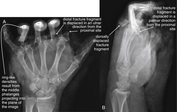
Figure 14-84 Phalangeal amputation.
This 39-year-old male sustained a crush injury to the left hand between the rollers of an industrial machine. A, Anterior–posterior view. Complete fracture of the proximal phalanges of the second through fifth digits is seen. Significant ulnar displacement of the distal fragments is seen for the second through fourth fingers. The PIP joints are held in flexion, resulting in the ringlike densities seen in these digits, which are projecting into the plane of the image. B, Lateral view. Additional palmar displacement of the proximal phalanx fractures is seen.
Soft-tissue gas is visible as a lucency on plain x-ray. Hand injuries and infections can result in penetration of gas into deep tissue planes, including tendon sheaths (Figure 14-85).
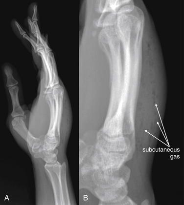
Figure 14-85 Subcutaneous emphysema, first metacarpal fracture.
This 25-year-old female was assaulted with a barbecue fork and sustained a stab injury to the right palm. X-rays were taken on the date of the injury. A, Lateral x-ray, demonstrating lucencies representing air tracking in the dorsum of the hand. These were not visible on the anterior–posterior view (not shown). B, Close-up, with contrast and brightness adjusted. Because of the risk for extensor tendon tenosynovitis from inoculation of the tendon sheath, the patient underwent exploration and irrigation in the operating room.
Lower Extremity Injuries and Pathology
Hip Injuries and Conditions of the Femoral Head
Hip fractures, hip dislocations, SCFE, and Legg-Calvé-Perthes disease (avascular necrosis of the femoral head) are discussed in detail in Chapter 13. MRI and CT of occult hip fracture are discussed in Chapter 15.
Femoral Shaft Fractures
Fractures of the femoral shaft are usually readily evident on x-ray (Figure 14-86). As with other fractures, the injury should be characterized by its location, angulation, distraction or overriding of fracture fragments, comminution, plane of fracture lines, involvement of articular surfaces, and evidence of open fracture or foreign body (see Table 14-3). The femur is a strong, weight-bearing bone that resists fracture except in cases of significant force, severe osteoporosis, or underlying pathology. Some bony tumors affect the femoral diaphysis (shaft), including Ewing sarcoma and osteosarcoma. When fracture occurs without a history of significant force, be sure to examine the x-ray for lytic bone lesions, periosteal reaction, and soft-tissue densities suggesting benign or malignant neoplasm.
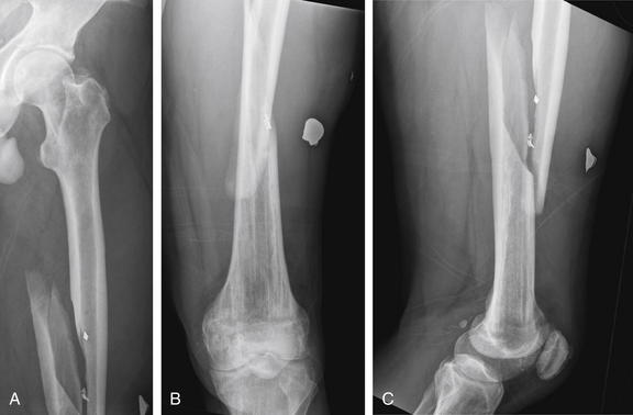
Figure 14-86 Midfemoral shaft fracture.
This 44-year-old male presented after a gunshot wound to the left thigh. His x-rays show a comminuted oblique fracture through the middiaphysis. The distal fragment is angulated. Radiopaque material representing shrapnel is visible. The small arrows on the images are radiopaque wound markers placed in the emergency department, not labels placed by the author. This patient was taken to the operating room for repair, at which time tight anterior and posterior thigh compartments were noted. The patient underwent anterior and posterior thigh fasciotomies, as well as intramedullary nail fixation of his femur fracture. Compartment syndrome is not a radiographic diagnosis; nonetheless, long-bone fractures of the lower extremities should prompt consideration of this diagnosis. Remember that compartment syndrome can also occur in the absence of fracture. A, B, Anterior–posterior (AP) views. C, Lateral view.
Femoral Condyle Fractures
In adults, femoral condyle fractures are also usually readily evident on x-ray (Figures 14-87 through 14-90). In addition to standard AP and lateral views, oblique x-rays may assist in detection of fractures. When uncertainty exists about the presence of a fracture, CT can be performed to provide additional delineation of injury.
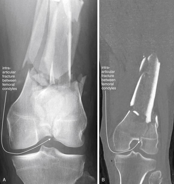
Figure 14-87 Distal femoral shaft fracture with intraarticular extension.
This 37-year-old male was struck by a car while riding a moped. His left lower extremity showed a significant deformity. A, AP x-ray view. B, CT coronal reconstruction of the same injury. Long-bone diaphyseal fractures are usually not diagnostic challenges in adults, but look carefully at the x-ray. On the AP view, a subtle lucency is present that appears to extend to the intercondylar notch, where a subtle cortical defect is visible. CT confirmed the intraarticular injury. Badly comminuted and displaced fractures carry a risk for vascular injury. This patient was also assessed for femoral and popliteal arterial injury—neither was present.
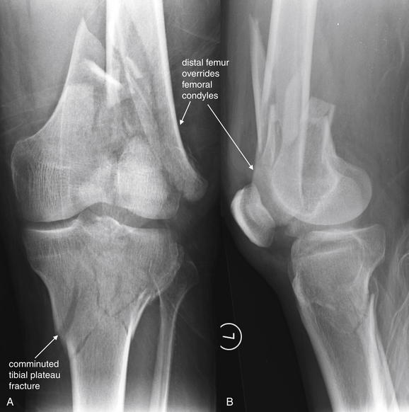
Figure 14-88 Distal femur fracture and proximal tibia fracture (tibial plateau).
This 39-year-old male crashed his car into a tree while intoxicated and complained of left leg pain. A, Anterior–posterior view. B, Lateral view. The patient’s fractures are not subtle, but some finer points are worth noting. First, the distal femur fracture not only is comminuted but also shows the distal fragment to be proximally dislocated, with the distal femoral shaft now overriding the femoral condyles. Both the distal femur and the proximal tibia are comminuted with intraarticular extension. Injuries such as these pose significant threat of arterial injury and compartment syndrome. Associated ligamentous injuries are likely but do not require emergency diagnosis. Compare with CT images in Figures 14-89 and 14-90.
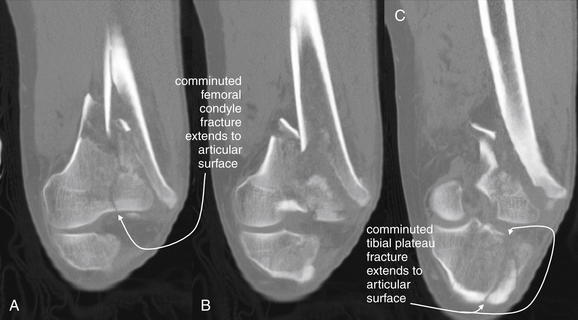
Figure 14-89 Distal femur fracture and proximal tibia fracture (tibial plateau), CT bone windows.
Same patient as in Figure 14-88. A through C, This series of coronal reconstructions shows the degree of comminution and intraarticular extension of both the tibial plateau and the distal femoral fractures. Although not performed in this case, CT angiography can be performed concurrently if vascular injuries are suspected.
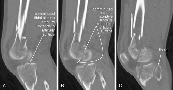
Figure 14-90 Distal femur fracture and proximal tibia fracture (tibial plateau), CT bone windows.
Same patient as in Figures 14-88 and 14-89. A through C, This series of sagittal reconstructions shows the degree of comminution and intraarticular extension of both the tibial plateau and the distal femoral fractures.
Patella Fractures and Dislocations
Patella fractures (Figures 14-91 and 14-92) can occur with direct force to the patella or with avulsion of the quadriceps or patellar tendon insertion sites. A lateral knee radiograph can demonstrate fractures in the axial plane. Patellar fractures can be difficult to visualize on AP views of the knee, because the patella overlies the denser distal femur. A sunrise view of the patella is obtained with the knee in flexion and the x-ray beam tangential to the patella, throwing the patella into relief by eliminating overlap of the patella with the femur and tibia. This can demonstrate vertical fractures not seen on an AP or lateral view. A bipartite patella is a normal variant that can simulate fracture. In the case of bipartite patella, the two patellar portions are usually rounded and smooth, rather than showing the irregular borders typical of fracture. Patella dislocation (Figure 14-93) is a common injury that does not require radiographic confirmation, because it is usually clinically evident and readily reduced at the bedside with simple knee extension. If x-rays are obtained, the patella usually appears laterally displaced on AP views.
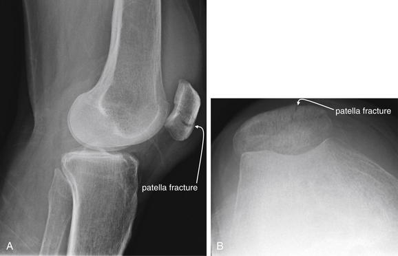
Figure 14-91 Comminuted patellar fracture.
This 74-year-old female with a history of osteoarthritis fell directly on her right knee. Anterior–posterior (AP), lateral, and sunrise views of the knee were obtained for suspected patellar fracture. The AP view (not shown in this case) is often unhelpful for this injury, because the patella overlaps with the distal femur. A, The lateral view projects the patella clear of the femur and reveals a comminuted, mildly displaced transverse fracture. B, The sunrise view, obtained with the knee in flexion, also projects the patella clear of the femur and shows an oblique fracture. The patient was treated with a knee immobilizer, with weight bearing as tolerated.
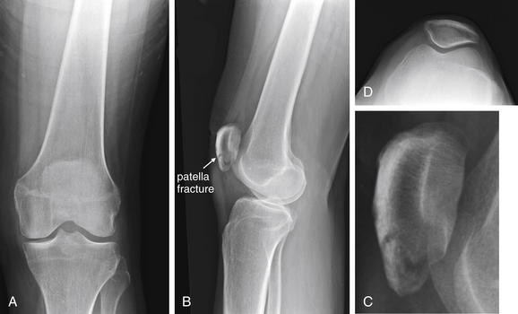
Figure 14-92 Patella fracture.
Like the patient in Figure 14-91, this patient fell directly on the knee, striking the patella. A, Anterior–posterior (AP) knee. B, Lateral knee. C, Close-up from BD, Sunrise view. In this case, the orientation of the fracture is primarily horizontal or transverse to the long axis of the leg. Consequently, the fracture line is not seen on the sunrise view. It is visible in the lateral view. On the AP view, the density of the femur obscures the fracture of the patella.
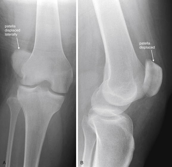
Figure 14-93 Patella dislocation.
This 34-year-old female was playing Nintendo Wii baseball when she swung the controller, twisting and falling on her right knee. The patella is subluxed laterally, evident in the anterior–posterior view (A). In the lateral view (B), the patella overlaps with the distal femur in an abnormal manner, because it has subluxed off of the patellar surface, a groove on the anterior surface of the distal femur between the medial and the lateral femoral condyles. Patellar dislocation does not usually require x-ray for diagnosis, nor are postreduction x-rays usually required. If fracture of the patella or other injuries are suspected, x-rays may be useful. The patient’s patella was reduced uneventfully. She also sustained a distal fibula fracture (not in field of view of these x-rays).
Tibial Plateau Fractures
Tibial plateau fracture (Figures 14-94 through 14-98) is a clinically important and sometimes relatively occult injury on plain radiographs. An important complication of tibial plateau fracture is compartment syndrome, occurring in up to 10% of cases.56 In addition, because the tibial plateau is a weight-bearing surface, fractures in this location typically require operative reduction to ensure the best possible anatomic alignment of fracture fragments. Although most tibial plateau injuries are seen on x-ray, subtle depressions of the tibial plateau surface may be difficult to recognize on AP and lateral x-rays. Obliquely oriented vertical fractures may be invisible on these views, and oblique projections should be obtained when injuries are suspected but not seen on standard views. CT of the tibial plateau can provide exquisite detail to delineate the fracture in multiple planes or even three-dimensionally and to aid in operative planning.57 In one study, CT modified the surgical plan in almost 60% of operative cases of tibial plateau fracture.58 Fractures with depression of greater than 5 mm typically require elevation and grafting.
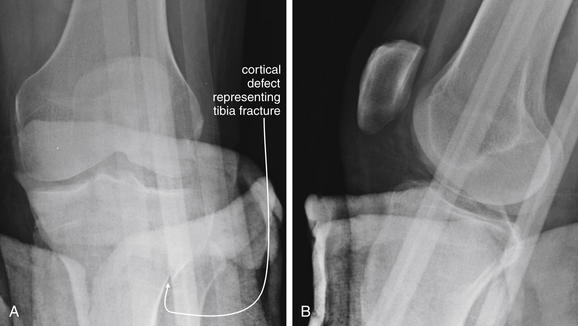
Figure 14-94 Tibial plateau fracture.
This 42-year-old male was struck by a car while riding a moped. He presented with leg pain and a pretibial wound. A, Anterior–posterior view of left knee. B, Lateral left knee. Although stabilization of open extremity fractures is of key importance, remember to remove unnecessary external foreign material whenever possible. These x-rays are quite limited because of splint materials in the field. Nevertheless, a fracture of the proximal tibia can be seen extending from the lateral metaphysis toward the articular surface. Computed tomography was performed to evaluate this injury further (Figure 14-95).
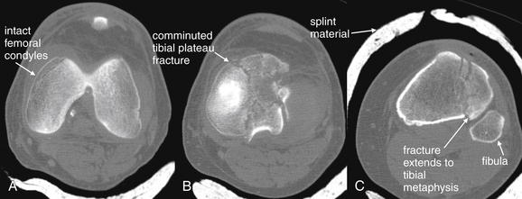
Figure 14-95 Tibial plateau fracture.
Same patient as in Figure 14-94. CT provides detailed information about articular fractures. These images taken from the axial CT series show the distal femoral condyles to be intact (A). The tibial plateau is comminuted (B), and the fracture extends to the lateral tibial metaphysis (C), as seen on the x-ray in Figure 14-94. Another advantage of CT is that it can image bone through overlying splint material. Because of its cost and radiation exposure, CT should not be used if adequate clinical information can be gathered with x-ray, so unnecessary splint materials should be removed before plain x-ray when possible to allow the best diagnostic images to be obtained.
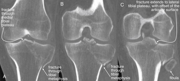
Figure 14-96 Tibial plateau fracture.
Same patient as in Figures 14-94 and 14-95. A through C, Coronal CT reconstructions demonstrate this tibial plateau fracture in more detail. For assessment of fractures, the scan is performed using 0.625-mm axial imaging with multiplanar reconstructions. There is a comminuted fracture involving the tibial plateau. The fracture line can be seen extending from the medial tibial plateau obliquely to the lateral tibial metaphysis. A branch of the fracture extends to the lateral tibial plateau as well. The articular surface of the lateral tibial plateau is slightly offset.
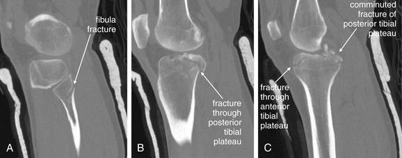
Figure 14-97 Tibial plateau fracture.
Same patient as in Figures 14-94 through 14-96. Here, sagittal computed tomography reconstructions reveal severe comminution of the posterior tibial plateau. In addition, a proximal fibula fracture is visible. A represents a lateral parasagittal plane. B and C progress medially.
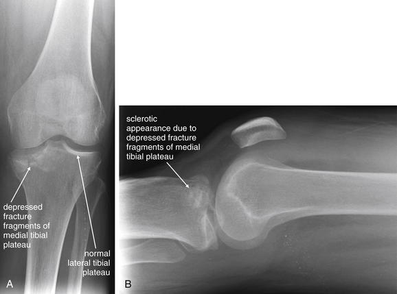
Figure 14-98 Tibial plateau fracture.
This 48-year-old female fell on her left knee in the bathroom. This relatively low-energy mechanism resulted in a depressed medial tibial plateau fracture—probably a complication of osteoporosis related to end-stage renal disease. A, Anterior–posterior view. Compare the smooth articular surface of the lateral tibial plateau with the medial plateau, which is irregular, comminuted, and depressed. The cortex appears discontinuous. B, Lateral view. The fracture is less evident here, but the anterior tibia appears sclerotic and dense because of overlapping depressed fracture fragments. CT (not shown) was performed to evaluate the injury more completely and to allow operative planning. The patient was treated with open reduction and internal fixation.
On the AP view, the intercondylar eminence (also called the tibial spine) is visible in the center of the tibial plateau. This structure serves as the attachment point for the anterior and posterior cruciate ligaments (on the anterior and posterior portions of the intercondylar eminence) and the medial and lateral menisci. Avulsion of this spine can occur with anterior and posterior cruciate ligament injuries (Figures 14-99 through 14-101). This relatively innocuous x-ray finding is clinically significant, because avulsion of the attachment point of these ligaments can render the knee unstable and often requires surgical fixation.59 Other subtle radiographic abnormalities can suggest important injuries. Lipohemarthrosis (fat–fluid level) can occur when a fracture has allowed marrow fat to enter the joint space. This is seen in the suprapatellar recess on a horizontal-beam lateral knee radiograph. On the AP projection, increased trabecular density beneath the lateral tibial plateau is abnormal. The trabecular density is normally greater beneath the medial plateau surface, because this region bears a greater load. Nonalignment of the femoral condyles and tibia on the AP view can also suggest tibial plateau fracture. In difficult cases, x-rays of the contralateral knee can reveal asymmetry suggesting fracture. These images are also useful in restoring leg length and alignment. Traction radiographs and a tibial plateau radiograph (an AP projection angled 15 degrees caudally) can reveal the depth of tibial plateau depression.60
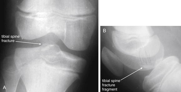
Figure 14-99 Tibial spine avulsion fracture.
This 7-year-old female fell while riding a bicycle. She complained of right knee pain and swelling. A, Anterior–posterior knee. B, Lateral knee. X-rays of the right knee show a subtle intercondylar eminence (tibial spine) fracture. Don’t believe it? Look carefully at her CT in Figure 14-100, and then return to these images. This injury may appear relatively innocuous, but it is a disabling injury requiring surgical repair. This is the tibial attachment point for the anterior cruciate ligament (ACL). Particularly in children, avulsion of the bony attachment, rather than ACL tear, may occur. Postoperative x-rays are shown in Figure 14-100. The patient underwent attempted arthroscopic repair, which was subsequently converted to an open repair.
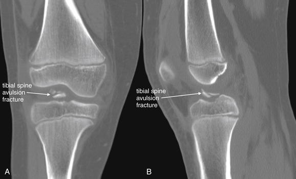
Figure 14-100 Tibial spine avulsion fracture.
Same patient as in Figure 14-99. A, Coronal CT reconstruction. B, Sagittal reconstruction. The tibial spine is avulsed at the insertion point of the anterior cruciate ligament (ACL). Compare with the x-rays in Figure 14-99. Clinically, this injury simulates ACL tear. Magnetic resonance imaging was not performed in this patient before operative therapy, because a tear of the ACL is unlikely to occur when the attachment has avulsed. Moreover, because operative repair with direct visualization is required, additional imaging is unnecessary.
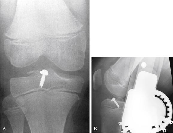
Figure 14-101 Tibial spine avulsion fracture.
Same patient as in Figures 14-99 and 14-100. Here, the tibial spine fracture fragment has been fixed in position with a surgical screw. A, Anterior-posterior view. B, Lateral view.
Ligamentous and Meniscus Injuries of the Knee
Ligamentous and meniscus injuries of the knee are common and may be completely occult on x-ray. Joint effusion may be visible but is not specific for ligamentous or meniscus injury. Avulsion of the tibial spine may be seen (see Figures 14-99 through 14-101). MRI is the current optimal imaging test for these injuries according to the American College of Radiology (ACR),57 but imaging need not be performed to assess for these injuries in the emergency department. Management is not acutely affected by results of imaging tests in most cases. Immobilization of the knee and outpatient follow-up are generally adequate. Timing of repair of anterior cruciate ligament injury is controversial, with studies suggesting that outcomes are no better with early than with late surgery in adults.
Knee Dislocations
Traumatic dislocation of the knee usually occurs with significant blunt trauma such as motor vehicle collisions, falls from height, and pedestrians struck by vehicles, although the injury can rarely occur with sports mechanisms such as football injuries and even with simple falls.61 This is a limb-threatening injury, associated with popliteal artery and nerve injuries, as well as disruption of all major ligaments of the knee. Spontaneous reduction of this unstable injury can occur, so x-rays demonstrating normal knee alignment do not rule out these important associated injuries. Vascular injury may occur in 20% of patients with posterior knee dislocation.62 On x-ray, posterior dislocation of the tibia relative to the distal femur is most often seen, although anterior dislocation can occur (Figures 14-102 through 14-105).
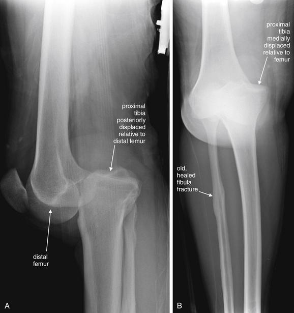
Figure 14-102 Knee dislocation, posterior.
This 29-year-old male fell down an embankment while intoxicated and was transported by emergency medical services to the emergency department, where he was noted to have no palpable pulses in his right foot. His knee appeared posteriorly dislocated on examination. He was unable to move his toes or ankle. Emergent knee reduction was performed in the emergency department, but the distal pulses remained absent even when sought by Doppler ultrasound. A, A lateral knee x-ray before reduction shows definite posterior dislocation of the tibia relative to the femur. B, An anterior–posterior view shows medial displacement of the tibia and fibula relative to the distal femur. Incidentally, the patient has an old, healed fibula fracture. This patient underwent angiography, shown in Figure 14-103.
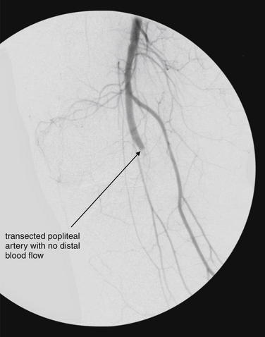
Figure 14-103 Knee dislocation with popliteal arterial injury.
Same patient as in Figure 14-102, with posterior knee dislocation. An arteriogram shows no flow beyond the popliteal artery at the level of the knee, consistent with severe arterial injury. Popliteal arterial injury is a limb-threatening injury associated with knee dislocation. When knee dislocation is known or suspected, popliteal artery injury must be strongly suspected and thoroughly evaluated. Spontaneous reduction of a dislocated knee can occur before emergency department arrival and should be suspected in cases of severe knee trauma. As described in the text, a meta-analysis suggests that physical examination is inadequate to exclude popliteal artery injury, although some small studies conclude otherwise. The gold-standard radiographic method for evaluation of popliteal arterial injury remains arteriogram. CT angiography appears to have sensitivity and specificity approaching that of conventional angiography. The sensitivity and specificity of ultrasound in this setting are not well characterized in the literature.
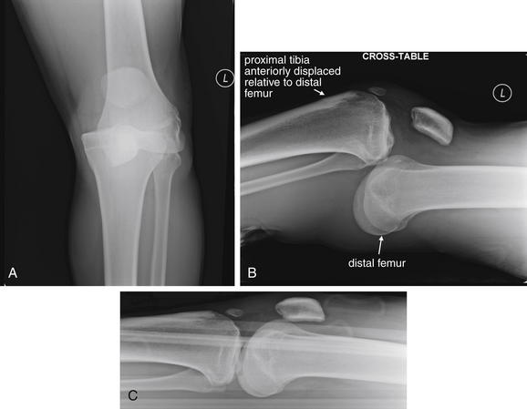
Figure 14-104 Knee dislocation, anterior.
This 18-year-old male sustained an anterior knee dislocation while playing football. Compare with the posterior knee dislocation in Figure 14-102. A, Anterior–posterior view before reduction. B, Lateral view before reduction. C, Lateral view after reduction. Beware of the possibility of spontaneous reduction of this unstable injury, which may then look normal on x-ray. If a knee dislocation is suspected, evaluate for popliteal artery injury. See the CT angiogram image from this patient in Figure 14-105.
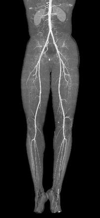
Figure 14-105 Knee dislocation, anterior, normal CT.
Same patient as in Figure 14-104. Because of suspected popliteal artery injury, the patient underwent CT angiography (CTA). Studies suggest that CTA is similar in sensitivity and specificity to conventional angiography for lower extremity injuries. Magnetic resonance angiography is an alternative with similar diagnostic ability for vascular injuries. In CTA, an intravenously injected contrast bolus is followed from the aorta into the lower extremities. Images can be reconstructed in any plane, and three-dimensional computer models can be rapidly built and manipulated. In this case, no vascular injury was found.
Can Physical Examination Exclude Vascular Injury, or Is Arterial Imaging Required in All Cases of Knee Dislocation?
Physical examination cannot adequately exclude arterial injury requiring surgery, according to a metaanalysis of seven studies with 284 injuries. Abnormal pedal pulses had a sensitivity of 79% (95% CI = 64%-89%) with a specificity of 91% (95% CI = 78%-96%).63 Scattered case series suggest higher sensitivity of physical examination for clinically significant injuries requiring surgery. Dennis et al.62 found absent pulses to be 100% sensitive for popliteal injuries requiring surgical repair, though some subtler intimal injuries and stenoses occurred in the presence of diminished or normal pulses. Abou-Sayed and Berger64 reported abnormal pedal pulses to be 100% sensitive for vascular injuries requiring intervention, but this small retrospective study of 52 patients does not prove the sensitivity of examination. At this time, imaging for arterial injury is prudent in patients with suspected or confirmed knee dislocation.
What Imaging Modalities Can Be Used to Evaluate Lower Extremity Vascular Injuries, Particularly of the Popliteal Artery?
The ACR gives conventional angiography, MRA, and CTA equal appropriateness (7 on its 1-to-9 scale) for evaluation of popliteal artery injury.57 No large studies exist directly comparing these modalities for popliteal artery injury. Because this injury can be time sensitive, with ischemia of the distal extremity a consideration, the most rapidly available test may be most appropriate. In most U.S. emergency departments, CTA is more widely available at all hours. MRA has the advantages of causing no radiation exposure and allowing simultaneous assessment of other structural damage to the knee, but it is relatively time-consuming and may interfere with other resuscitative actions for the patient. Conventional angiography is invasive but offers treatment options such as endovascular stenting in the case of isolated vascular flaps.65-66
Rieger et al.67 retrospectively reviewed 87 cases of suspected traumatic extremity arterial injury and found the sensitivity of CTA to be 95% with 87% specificity, compared with a mixed diagnostic standard including surgery, angiography, clinical follow-up, and radiologic follow-up. Other small studies suggest high sensitivity and specificity of CTA.67a-c
In a review article, Fleiter and Mervis68 concluded that CTA can replace conventional angiography in patients with both blunt and penetrating extremity injuries.
Potter et al.69 compared the results of MRA and conventional angiography in six patients with severe multiligament knee injuries and found 100% agreement, though only two arterial injuries were identified, leaving wide CIs. However, MRA compares favorably with CTA and conventional angiography for vessels of similar size in the head and neck, suggesting that it would be accurate in the setting of extremity trauma.
Tibial Stress Fractures
Tibial stress fractures can occur with repetitive exercise in runners and other athletes, particularly in young patients. The tibia accounts for nearly 50% of stress fractures in athletes. Initial x-rays are abnormal in only about 10% of cases70 but should be performed to evaluate for competing diagnoses, including complete fracture, osteomyelitis, or malignancy.71 Later in the course, the x-ray appearance of healing stress fractures includes localized periosteal reaction, endosteal thickening, and radiolucent cortical lines. Stress fractures in cancellous bone may be visible as a radiolucent fracture line, whereas in cortical bone, cortical thickening may be the only evidence of fracture.71 Bone scan and MRI can be used for diagnosis in uncertain cases; the primary emergency indication for these studies is not to confirm stress fracture but to exclude more serious causes of pain such as bone infection or tumor, which can have similar x-ray appearances.72
Tibial and Fibular Shaft Fractures
The tibia is the most commonly fractured long bone, with an incidence of 2 per 1000 annually. Tibial and fibular shaft (diaphyseal) fractures are typically radiographically evident on plain x-ray (Figure 14-106). These fractures should be characterized using standard terms as described in Table 14-3, although more specific classification schemes are described in the orthopedic literature and used for prognosis and therapeutic planning. Often, fractures of both the tibial and the fibular shaft occur together. Tibial shaft fractures are high-energy injuries and can be associated with compartment syndrome in up to 7% of cases.73 The presence of tibial fracture does not guarantee compartment syndrome, nor does the absence of fracture exclude it.
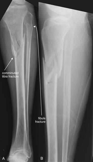
Figure 14-106 Tibial and fibular shaft fractures.
This 54-year-old female with a history of chronic steroid use slipped on water in her home and sustained a left lower extremity injury. Her x-rays show a proximal tibial diaphysis fracture that is comminuted. The distal fragment is somewhat anteriorly displaced relative to the proximal fragment. In addition, the proximal fibula has a transverse fracture. A, Anterior–posterior view. B, Lateral view. Diaphyseal fractures of long bones in adult patients are usually not a diagnostic challenge on plain x-ray. Important points for this case are the association of tibial fractures with fibular fractures. Because of the strong syndesmosis (intraosseous membranous joint), these two bones act like a ring under stress, and force transmitted through one bone often generates tension resulting in fracture of the other. Moreover, tibial fractures are associated with lower extremity compartment syndrome. Patients should be carefully instructed on symptoms and signs of compartment syndrome, and monitoring with repeated examinations or actual compartment pressure measurements should be considered. This patient underwent closed reduction and intramedullary fixation of the tibial fracture. Her compartment pressures were monitored but did not become elevated.
Open tibial fractures are surgical emergencies and should generally undergo debridement and irrigation within 6 hours.
Ankle Mortise Injury
The ankle mortise is the true ankle joint formed by the articulation of the distal fibula, distal tibia, and talus. The fibula forms the lateral border of the mortise, whereas the tibia forms the proximal and medial borders. Mechanisms leading to fractures of this structure include inversion injuries and impaction. Fractures can be described as unimalleolar, bimalleolar, or trimalleolar. Trimalleolar fractures include the lateral malleolus (distal fibula), medial malleolus (medial distal tibia), and posterior malleolus (posterior distal tibia). More specific classification schemes are described in the orthopedic literature. A variety of eponyms are applied to describe various ankle mortise fracture patterns, including Maisonneuve fractures, pilon fractures, bimalleolar (Pott) fractures, trimalleolar (Cotton) fractures, triplane fractures, and snowboarder’s fracture. In children, Salter-Harris fractures of the distal tibia, including Tillaux fractures, are common and often radiographically subtle.
Maisonneuve Fractures
Maisonneuve fractures involve the proximal third of the fibula and the distal tibia, usually the medial malleolus (Figure 14-107). In some cases, the deep deltoid ligament ruptures, sparing the medial malleolus from fracture. Tearing through the interosseous membrane and distal tibiofibular syndesmosis also occurs. This pattern of injury resembles the Galeazzi and Monteggia patterns seen in the forearm (discussed earlier in this chapter). As with those injury patterns, care must be taken not to overlook the second injury.
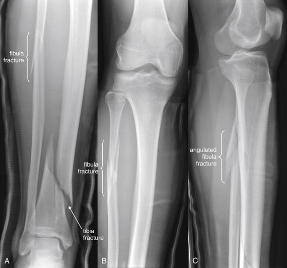
Figure 14-107 Maisonneuve fracture.
This 29-year-old male was tackled playing rugby and complained of right lower extremity pain. His x-rays show an obvious fracture of the distal tibial metaphysis. His proximal fibular diaphysis fracture is subtler. On the anterior–posterior views (A, B), this appears minimally displaced and angulated, although the lateral view (C) tells a different tale. A fibular fracture fragment is displaced and angulated. The combination of a distal tibial fracture and a proximal fibula fracture fits the Maisonneuve fracture pattern. Often, this pattern involves the medial or posterior malleoli of the tibia, or the tibia itself may not be fractured but a significant ankle sprain with injuries of the deltoid ligament or anterior talofibular ligament may be present. When injuries to the distal tibia or ankle ligaments are present, inspect the proximal fibula carefully for fracture. The proximal fibula fracture does not require surgical fixation, but long leg casting is typical. This patient had an external fixator placed because of the severity of his tibial fracture.
Tibial Plafond Fractures (Pilon Fractures)
Fractures of the distal tibia are sometimes called pilon fractures, for hammer, referring to the compression nature of these injuries (Figure 14-108). Common mechanisms include vertical loading from falls from height, motor vehicle collision, and sporting mechanisms such as skiing. The talus is driven into the distal tibia, usually resulting in intraarticular injury, including comminuted fractures of the medial malleolus, anterior margin of the distal tibia, and transverse fractures of the posterior tibia. Of these injuries, 20% to 25% are open, and 75% are associated with fibula fractures. Other associated injuries include vertebral compression fractures, pelvic and acetabular injuries, vascular injuries, and compartment syndrome.74
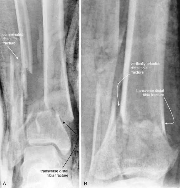
Figure 14-108 Tibial plafond fracture (pilon fracture).
Tibial plafond or pilon fractures are compression injuries of the ankle and distal tibial metaphysis, often with intraarticular comminution. The medial malleolus (tibia), anterior tibia, and posterior tibial surfaces are usually fractured. The fibula is also fractured in about 75% of cases. These injuries occur from major trauma mechanisms and are associated with compartment syndrome, vertebral compression fractures, pelvic injuries, and vascular injuries. Pilon fractures are often open injuries. This 30-year-old male fell 30 feet from the roof of a house, landing on his feet. He had an open ankle injury on emergency department arrival, with protrusion of the medial malleolus. A, Anterior–posterior view. B, Lateral view. Fiberglass cast material partially obscures bony detail. However, a transverse comminuted, laterally displaced distal tibia fracture is present. A vertically oriented fracture of the posterior tibia is also present. The patient was treated with an external fixator.
A variety of classification schemes have been described and are used to plan surgical reconstruction and fixation. For the purposes of the emergency physician, describing these fractures using standard terminology is sufficient.
CT scan is valuable in delineating these complex injuries and planning surgical repair. Conventional angiography or CTA should also be performed if associated vascular injury is suspected.
Other Ankle Mortise Fracture Patterns
Bimalleolar (Pott) fractures involve two of three malleoli: lateral (fibula), medial (tibia), and posterior (tibia). These unstable fractures require orthopedic fixation. Trimalleolar (Cotton) fractures involve all three malleoli and are unstable, requiring fixation (Figure 14-109).
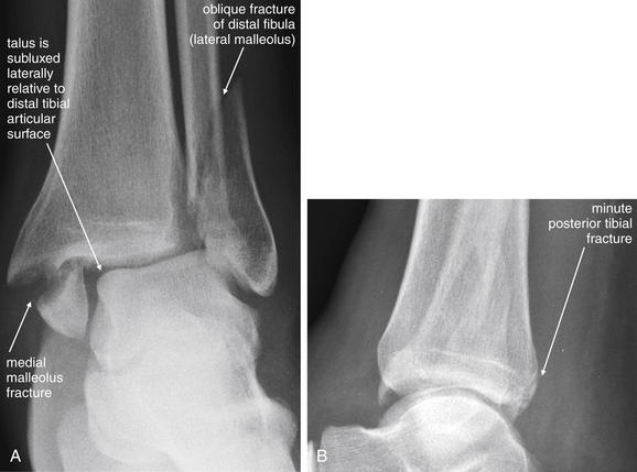
Figure 14-109 Ankle mortise injury (trimalleolar).
This 48-year-old male fell from his bicycle while intoxicated and was unable to bear weight on his left ankle. His examination showed significant swelling of both malleoli. A, Anterior–posterior x-ray. The medial malleolus of the tibia is fractured and displaced. The lateral malleolus (composed of the distal fibula) is also obliquely fractured, with lateral displacement of the fracture fragment. The talus is laterally displaced with respect to the distal tibia. This is a highly unstable fracture, because the bony attachment sites of multiple ligaments of the ankle are avulsed. B, Lateral x-ray. The posterior distal tibia also appears to have a small fracture, making this a trimalleolar fracture. The patient underwent open reduction and internal fixation.
A Tillaux fracture is Salter-Harris III injury of anterolateral tibial epiphysis caused by eversion and lateral ankle rotation, most common in adolescents, in whom the medial epiphyseal plate has closed, whereas the lateral physis remains open (Figure 14-110).75 Other Salter-Harris injuries of the distal tibia and fibula are shown in Figures 14-111 through 14-113.
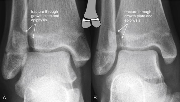
Figure 14-110 Tillaux fracture, a Salter-Harris III tibial fracture.
This 12-year-old female was playing softball when she slid into home plate and injured her ankle. She has been unable to ambulate because of pain. Her x-rays show a Tillaux fracture, an eponym for an anterolateral tibial epiphyseal fracture, extending to the physis (growth plate). This is a Salter-Harris III injury. The mechanism is external foot rotation with avulsion fracture because of the strength of the anterior tibiofibular ligament. This is common in adolescents but rare in adults, in whom rupture of the ligament usually occurs, rather than fracture. This patient underwent open reduction and internal fixation of the right anterolateral tibial epiphysis. A, Anterior–posterior view. B, Oblique view.
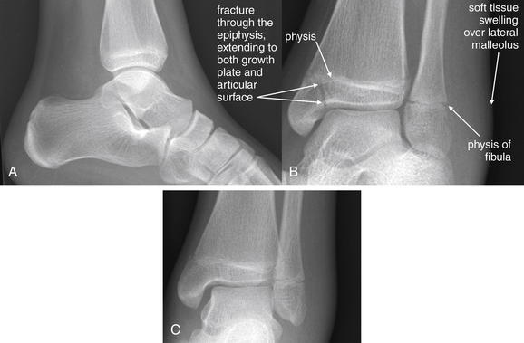
Figure 14-111 Nondisplaced Salter-Harris III fracture of the tibia, with nondisplaced Salter-Harris I fibula fracture.
This 14-year-old basketball point guard inverted her ankle during a game and was unable to walk. A, Lateral view. B, Oblique view. C, Anterior–posterior view. A lucent fracture line runs through the medial malleolus of the tibial epiphysis and extends to the physis. This is nondisplaced but extends to the articular surface as well. Though fracture through the physis cannot be directly seen, extension of the fracture through the growth plate should be assumed, making this a Salter-Harris III fracture. Note the significant swelling overlying the lateral malleolus. Although no fracture is seen, a nondisplaced Salter-Harris I distal fibula fracture may be present, and empiric treatment should be instituted. Remember that ankle sprains in children should be assumed to represent Salter-Harris I fractures, which are fractures through the growth plate only. When nondisplaced, these are radiographically occult. The patient was placed in a bivalved, short-leg cast to allow for swelling.
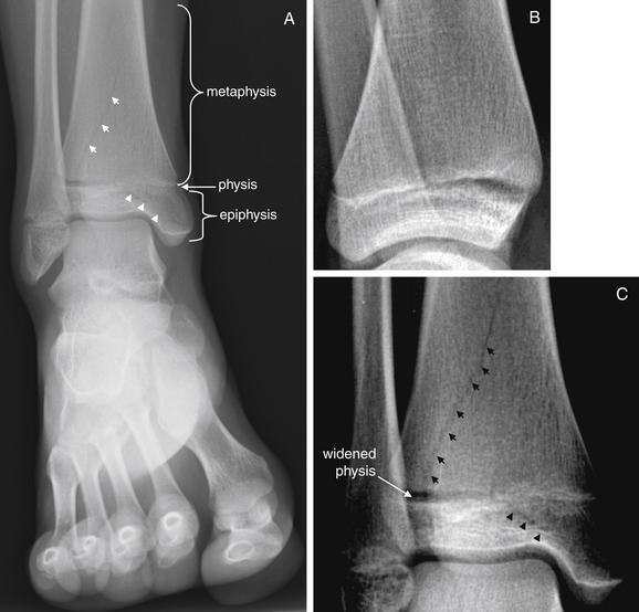
Figure 14-112 Nondisplaced Salter-Harris IV fracture of the tibia.
This 12-year-old female tripped while running and twisted her right ankle. She had immediate pain and was unable to bear weight. Examination showed swelling and tenderness over both malleoli. A, Anterior–posterior view of the ankle. B, Lateral view of the ankle. C, Close-up from A, with contrast altered to emphasize fracture lines. The x-ray shows a Salter-Harris IV fracture, defined as a fracture crossing through the physis (growth plate) and involving both the metaphysis and the epiphysis. Salter-Harris IV fractures may interfere with normal growth, even with perfect reduction. Displaced fractures of this type require open reduction and internal fixation. In this case, an oblique fracture extends from the distal tibial metaphysis (short arrows), through the growth plate, and into the epiphysis (arrowheads). Also notice the widened physis in the lateral tibia. Computed tomography of the same injury is shown in the Figure 14-113. The patient underwent posterior splinting followed by 6 weeks of cast treatment with good outcome. Because of the risk for poor outcomes even in optimally treated cases, clear discussion of the natural history of the injury with the patient, documentation of the discussion, and orthopedic consultation or referral are advised.
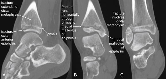
Figure 14-113 Nondisplaced Salter-Harris IV fracture of the tibia.
Same patient as in Figure 14-112. Computed tomography reconstructions in sagittal (A) and coronal (B, C) planes reveal the extent of the fracture. A, The fracture line is seen running through the distal metaphysis, crossing the physis, and then exiting the anterior epiphysis without involving the articular surface. B, The fracture extends horizontally through the growth plate and into the medial malleolus of the epiphysis. C, In another coronal plane, the fracture is seen extending into the distal metaphysis. Injuries extending from the metaphysis, through the physis, and into the epiphysis are Salter-Harris IV fractures.
A triplane fracture combines distal tibial fractures in coronal, sagittal, and transverse planes. Distal fibula fractures commonly occur with these injuries. Like the Tillaux fracture, this injury usually occurs in early adolescence, when the medial tibial physis has closed but the lateral physis remains open. The coronal fracture line is typically best seen on the lateral x-ray and involves the posterior tibial metaphysis and a portion of the epiphysis. The sagittal fracture is seen best on AP views and is a vertically oriented fracture through the epiphysis, usually at a midportion of the tibial plafond. It can occur at any portion of the anterior epiphysis and extends in variable directions. The axial fracture occurs through the physis and is often difficult to see on x-ray. CT is useful to characterize these fractures further.
Triplane fractures can occur as two-, three-, and four-part fractures. Two-part fractures are most common and are a Salter-Harris IV fracture of the distal tibia. Two fracture fragments are produced: (1) the lateral portion of the epiphysis attached to a posterior metaphyseal spike and (2) the distal tibia with the anteromedial epiphysis attached.
Three-part triplane fractures appear as Salter-Harris III fractures on AP view and as Salter-Harris II fractures on lateral view. Three fracture fragments are produced: (1) a rectangular fragment of the anterolateral epiphysis, (2) the remainder of the epiphysis with an attached posterior spike of the distal tibial metaphysis, and (3) the tibial shaft with the anteromedial epiphysis.76-77
Four-part triplane fractures are similar to three-part fractures, with the addition of a fourth fragment from the medial malleolus.
Talus Fractures
Talus fractures (Figures 14-114 and 14-115) can occur in association with other ankle mortise or pilon injuries. In addition, a lateral talus process fracture called a snowboarder’s fracture can occur with extreme dorsiflexion of the ankle. X-rays are normal in 40% of cases.78 CT is often needed for diagnosis of this occult injury and should be considered in snowboarders with lateral ankle pain and normal plain films.79
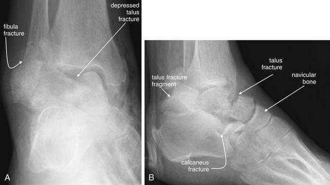
Figure 14-114 Talus and calcaneal fractures.
This 80-year-old female was in a severe motor vehicle collision and presented with injuries to her distal right lower extremity. A, Anterior–posterior view. B, Lateral view. A depressed talus fracture is visible. In B, this fracture is seen to run through the midbody of the talus. A also demonstrates a distal fibula fracture, whereas in B, a calcaneal fracture is seen. The patient underwent CT to characterize these fractures further (Figure 14-115).
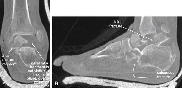
Figure 14-115 Talus and calcaneal fractures, CT.
Same patient as in Figure 14-114. CT was performed to characterize in detail fractures seen on x-ray. A, Coronal reconstruction. The lateral half of the talus is missing from the image because it has been retropulsed, as seen in B. B, Sagittal reconstruction. The talus and calcaneus fractures are shown in detail. A large talar fragment is dislocated posteriorly. Axial, coronal, and sagittal CT reconstructions can make the three-dimensional detail of fractures evident. This CT also revealed a cuboid fracture not seen on the x-ray.
Tibiotalar and Subtalar Dislocations
Forceful plantar flexion and inversion or eversion stress can result in tibiotalar dislocation (often called ankle dislocation) or subtalar dislocation (Figures 14-116 and 14-117). Motor vehicle collisions or falls from height are common causes, though forceful lateral motion during sports occasionally can result in this injury, because the ankle joint bears a force equal to several times the body weight during these activities. Fractures of the talus and of the tibial or fibular malleoli are commonly present, resulting from the high energy required to dislocate the tibiotalar joint. Posterior dislocation is most common. These injuries can be open, and vascular injury can result even from closed injuries. High-degree ligamentous injuries occur with this dislocation.80
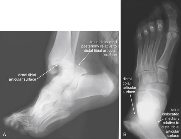
Figure 14-116 Tibiotalar dislocation.
This 17-year-old male landed on his left ankle after dunking a basketball, sustaining a deformity. His tibiotalar joint is dislocated, with the talus dislocated posteriorly (visible on the lateral view, A) and medially (visible on the anterior–posterior view, B). No fractures are present in this case, although fractures are commonly associated with this injury because of the amount of force required to dislocate the ankle. This was an open injury, and the patient underwent exploration, irrigation, and debridement with primary closure.
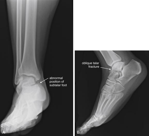
Figure 14-117 Subtalar dislocation with talar fracture.
This 38-year-old male presented with an ankle deformity following a motorcycle collision. A, Anterior–posterior ankle, obtained on ED arrival. The talus is positioned normally in the ankle mortise. The alignment of the talus with the calcaneus is abnormal, with the calcaneus and remainder of the distal foot displaced medially. This is a subtalar dislocation and was reduced immediately because of concern for vascular compromise. B, Lateral foot, obtained after reduction. An oblique fracture through the talus is visible.
Calcaneal Fractures
Calcaneal fractures (Figures 14-118 through 14-120) classically occur with falls from height, although motor vehicle collisions are another common cause. Associated injuries include lumbar and thoracic compression fractures. Compartment syndrome of the foot can complicate high-energy calcaneus fracture. Stress fractures of the calcaneus without associated injuries can result from long marches, such as by military personnel. Compression of the calcaneus results in loss of height, visible on lateral x-ray as a decrease in the Bohler (sometimes spelled Boehler or Böhler) angle (see Figures 14-118 and 14-119).81 The Bohler angle is determined by drawing a line from the posterior superior aspect of the calcaneus through the highest point of the posterior subtalar articular surface (the apex of the calcaneus). A second line is drawn from the highest point of the anterior process of the calcaneus to the posterior margin of the subtalar surface of the calcaneus. The angle formed by the intersection of the two lines is the Bohler angle. A normal Bohler angle is 20-40 degrees, with values less than 20 degrees strongly suggesting fracture. Isaacs et al.82 studied 212 patients with calcaneus fracture and 212 normal controls. A Bohler angle less than or equal to 20 degrees was 99% sensitive and specific for calcaneus fracture, with a positive likelihood ratio of 110. However, larger Bohler angles, although 100% sensitive, were less specific for fracture: an angle below 25 degrees was only 82% specific, with a positive likelihood ratio of 5, and below 23 degrees was 89% specific, with a positive likelihood ratio of 9. Knight et al.83 found the Bohler angle to have excellent interrater reliability for emergency physicians. However, emergency physicians in this study were highly accurate (97.9%) in diagnosing calcaneus fractures without the assistance of the Bohler angle. The accuracy of emergency physicians in this study may not reflect real-world practice, because the physicians were specifically asked to evaluate x-rays for the presence of calcaneal fracture.
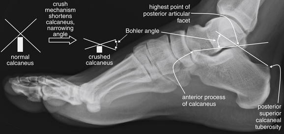
Figure 14-118 Normal calcaneus and the Bohler angle.
Most calcaneal fractures are compression injuries from falls from height. The Bohler angle is a measurement used to identify subtle compression fractures. To measure the Bohler angle, first draw a line from the posterior superior calcaneal tuberosity to the highest point of the posterior articular facet. Next, draw a second line from the posterior articular facet to the anterior process. The intersection of these lines forms the Bohler angle, which is normally between 20 and 40 degrees. With compression fracture of the calcaneus Figure 14-119), the posterior articular facet is usually crushed into the body of the calcaneus and is not as tall as normal. As a result, the lines crossing at this point form a narrower angle. Values of the Bohler angle that are less than 20 degrees are considered abnormal. Sometimes the calcaneus is flattened so much that the Bohler angle is 0 degrees, though these injuries are usually not so subtle as to require measurement of the Bohler angle for recognition.
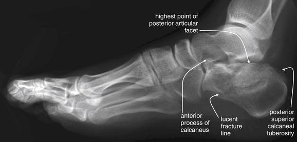
Figure 14-119 Calcaneal fractures.
This 39-year-old male crashed his car into a tree. He complained of significant right leg and foot pain. His x-rays show a comminuted fracture of the calcaneus. For an obvious fracture such as this, measurement of the Bohler angle may be unnecessary, but it is helpful to consider this extreme case to understand the value of the measurement for subtler cases. Look at the normal calcaneus in the prior figure. The apex of the posterior articular facet normally forms a peak atop the calcaneus. In this case, the peak has been flattened. The two lines would each be horizontal and would form an angle of 0 degrees. This is a comminuted fracture, with a lucent fracture line running obliquely from the inferior margin of the anterior calcaneus to the superior margin of the posterior calcaneus. Computed tomography was also performed to define this fracture in more detail.
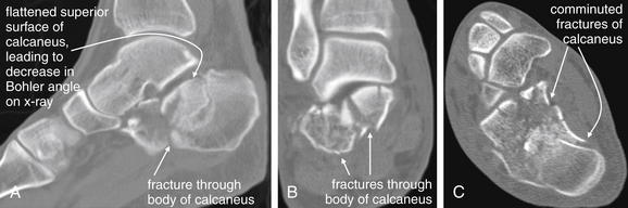
Figure 14-120 Calcaneal fractures, CT.
Same patient as in Figure 14-119. The scan demonstrates a badly comminuted fracture of the calcaneus. A, Sagittal reconstruction. As in the lateral x-ray in Figure 14-119, the normal apex of the posterior articular facet can be seen to be depressed as a consequence of the fractures, giving the calcaneus a flattened upper contour. For this reason, the Bohler angle on the lateral x-ray was nearly 0 degrees. A coronal reconstruction (B) and an axial reconstruction (C) show the calcaneus to be severely fragmented.
In uncertain cases, CT is valuable in identifying and characterizing these fractures, which are often comminuted and intraarticular.84
Achilles Tendon and Ligamentous Injuries of the Ankle
As described earlier, clinical decision rules can guide ordering of x-rays of the foot and ankle, allowing x-rays to be avoided in many cases of sprain without fracture. Ligamentous injuries of the ankle are common, accounting for about 85% of ankle injuries. In most cases, diagnostic imaging is not indicated in the emergency department to confirm these injuries. MRI is considered by the ACR the diagnostic imaging standard for ligamentous injury.85
Tarsal Fractures
Tarsal fractures (Figure 14-121) can be difficult to diagnose by plain x-ray, resulting from the confluence of the outlines of the tarsal bones, talus, and calcaneus. The tarsal bones include the navicular (named for its sail shape on AP x-ray), cuboid (named for its cubelike shape), and three cuneiform bones: the medial, intermediate (sometimes called middle), and lateral. When fracture is suspected but is not seen on plain x-ray, CT scan can provide fine anatomic detail to delineate fractures. No large studies have compared the sensitivity of x-ray and MRI for tarsal fractures, but small studies suggest x-ray to be insensitive.
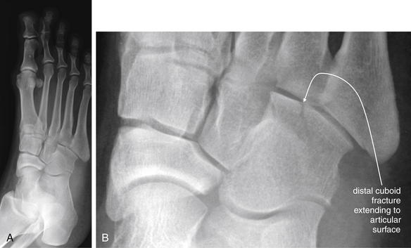
Figure 14-121 Cuboid fracture.
This 41-year-old fell, twisting her right foot. She was unable to walk because of pain in her lateral foot. A, An oblique view of the foot, shown for context. B, Close-up. A fracture of the distal cuboid is visible, extending to the articular surface with the metatarsals. This is nondisplaced. This fracture was not readily seen on the anterior–posterior and lateral views (not shown). The patient was treated with a CAM walker boot and without bearing weight for 4 to 6 weeks. This figure also demonstrates a normal Lisfranc joint. Abnormalities of the Lisfranc joint are discussed in Figures 14-122 and 14-123.
Preidler et al.86 prospectively compared x-ray (including resting and stress views), CT, and MRI in 49 patients with acute hyperflexion injuries of the foot. The authors did not report sensitivity and specificity values, because a well-defined diagnostic standard was not available in all patients. However, x-ray revealed only 33 metatarsal and 20 tarsal fractures, whereas CT revealed 53 metatarsal and 41 tarsal fractures in the same patients. Magnetic resonance revealed 41 metatarsal fractures and 18 metatarsal “bone bruises,” with 39 tarsal fractures and 9 tarsal bone bruises. The authors concluded that conventional x-ray is inadequate and that CT should be the primary imaging technique for patients with acute hyperflexion foot injuries. Presumably, other acute midfoot injuries might show similar patterns of greater diagnostic sensitivity of CT and MRI.
Peicha et al.87 prospectively compared x-ray with stress views, CT, and MRI in 75 consecutive patients with acute hyperflexion foot trauma. X-ray revealed 48 metatarsal and 24 tarsal fractures, CT showed 86 metatarsal and 74 tarsal fractures, and MRI detected 85 metatarsal and 100 tarsal fractures. The authors concluded that x-ray is inadequate in diagnosis of acute hyperflexion foot injuries.
Tarsometatarsal Joint Fractures and Dislocations (Lisfranc Fracture)
Hyperflexion injuries to the foot can result not only in fractures but also in dislocations of the tarsometatarsal joint, called the Lisfranc joint (Figures 14-122 and 14-123). This injury is both notoriously difficult to diagnose radiographically and clinically important, because significant osteoarthritis and poor long-term outcomes can occur in patients with this injury who do not undergo adequate surgical fixation. Poor outcomes are common even in patients who are properly treated, but misdiagnosis is a source of medical–legal liability for emergency physicians. Normally, the tarsometatarsal joint is well aligned, with little separation of the first and second metatarsals and closely apposed medial and middle cuneiform bones. The lateral aspect of the first metatarsal should align with the lateral aspect of the medial cuneiform bone. The medial border of the second metatarsal should align with the medial border of the middle cuneiform bone. Ligaments join the second and third metatarsals, the third and fourth metatarsals, and the fourth and fifth metatarsals at their bases. However, no ligament stabilizes the space between the first and the second metatarsals, making this a potentially unstable region. Instead, a ligament joins the medial cuneiform bone to the base of the second metatarsal—called the Lisfranc ligament (see Figure 14-122). This ligament is often disrupted in the Lisfranc injury. The Lisfranc injury is characterized on x-ray by splaying of the distance between the first and the second metatarsals and often of the space between the medial and the middle cuneiform bones. Fractures may also be seen. Traditionally, if resting x-rays do not show splaying of the joint space, stress (weight bearing) x-rays are obtained to exaggerate the joint distance if an unstable joint is present.
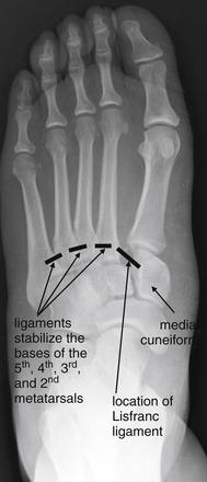
Figure 14-122 Tarsometatarsal joint fracture dislocations (Lisfranc fracture).
The tarsometatarsal joint is subject to fracture and dislocation with hyperplantar flexion of the foot. Ligaments join the fifth and fourth, the fourth and third, and the third and second but not the second and first metatarsal bases. Instead, a ligament joins the second metatarsal and medial cuneiform bones. This is called the Lisfranc ligament and can be disrupted, as in this image. Though the ligament itself is not visible on x-ray, disruption widens the space between the first and the second metatarsals and between the second metatarsal and the medial cuneiform. Compare with the normal Lisfranc joint in Figure 14-121, as well as the abnormal joint in Figure 14-123.
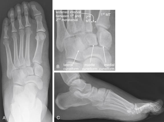
Figure 14-123 Tarsometatarsal joint fracture dislocations (Lisfranc fracture).
This 29-year-old female presented with pain in the left midfoot after falling down two steps. She was unable to bear weight because of pain. A, Anterior–posterior view of the foot (B, close-up). Look carefully at the metatarsal–tarsal joints. The medial aspect of the second metatarsal (MT) does not align with the medial aspect of the middle cuneiform, and a small osseous fragment is seen. The distance between the first and the second MTs is wider than normal. This subtle injury is a Lisfranc joint fracture dislocation. The lateral film (C) does not reveal this injury. The patient underwent open reduction and internal fixation.
Several small studies have examined advanced imaging techniques in comparison with x-ray for detection of the Lisfranc joint injury.
Preidler et al.88 retrospectively reviewed MRI findings in 11 patients with Lisfranc injuries, 5 with x-rays for comparison. X-ray showed tarsometatarsal joint widening in all 5 patients, and tarsal and metatarsal fractures were seen in 4 patients. MRI showed Lisfranc joint malalignment in all 11 patients and a disrupted Lisfranc ligament in 8. In the 3 patients with intact Lisfranc ligaments, an avulsion fracture was seen either in the second metatarsal base or in the medial cuneiform bone at the site of ligament insertion. MRI also showed metatarsal base and tarsal bone fractures in 10 patients. This small series proves little about the sensitivity of x-ray or MRI, but the authors suggested MRI should be used in patients with inconclusive x-ray findings.
Preidler et al.86 then prospectively compared x-ray with stress views, CT, and MRI in 49 patients with hyperflexion foot injuries, as described earlier in the section on tarsal fractures. Resting and stress x-ray each revealed 8 cases of Lisfranc joint malalignment; stress views did not detect any cases not seen already with resting x-ray. CT scan revealed 16 Lisfranc joint malalignments. MRI showed Lisfranc joint malalignment in 16 patients, including 11 cases with Lisfranc ligament disruption. The authors concluded that x-ray is inadequate for detection of this injury. Assuming that CT and MRI were correct in all cases, x-ray was only 50% sensitive for detection of this important injury.
Peicha et al.87 prospectively compared x-ray with stress views, CT, and MRI in 75 consecutive patients with acute hyperflexion foot injuries. Resting x-ray showed 17 cases of Lisfranc joint injury, and stress views showed no additional injuries. CT showed 31 cases of Lisfranc joint malalignment and 4 cases of bony avulsion of the Lisfranc ligament. MRI detected 31 cases of Lisfranc joint malalignment and 22 partial or complete tears of the Lisfranc ligament. Again, x-ray was inadequate to detect Lisfranc joint injury, with a sensitivity of only 55% compared with a standard of CT or MRI.
Crim89 reviewed the literature and concluded that data on the diagnostic accuracy of MRI was lacking. This is because of the paucity of studies in which MRI findings are confirmed against an independent diagnostic standard, such as surgical findings.
Metatarsal Fractures
Metatarsal fractures (Figures 14-124 and 14-125) can occur from a variety of mechanisms, including hyperflexion foot injuries, as described earlier; direct foot blunt or penetrating trauma; or ankle inversion injuries. Fractures can occur at any point along the course of the metatarsal. However, certain patterns are most clinically important. Metatarsal base fractures may occur in conjunction with Lisfranc joint injuries, as described earlier. Metatarsal fractures are common and occur as much as 10 times more often than Lisfranc injuries.
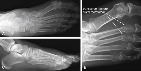
Figure 14-124 Metatarsal fractures.
This 50-year-old patient fell, inverting her left foot. She presented with pain and swelling in her distal midfoot. A, Anterior–posterior view, showing transverse fractures of the distal second and third metatarsal diaphyses, with slight lateral angulation but without intraarticular extension. B, Close-up. C, Lateral view, which does not show these injuries. The patient was treated with a posterior short-leg splint and non-weight-bearing status.
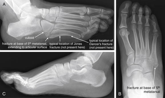
Figure 14-125 Fifth metatarsal fractures.
This 29-year-old woman fell down two steps, inverting her right foot and ankle. She complained of pain with weight bearing and was unable to walk four steps in the emergency department. She had tenderness over the proximal fifth metacarpal. Because she failed the Ottawa ankle rule, x-rays were obtained. A, Oblique view. B, Anterior–posterior view. C, Lateral view. A proximal fracture of the fifth metatarsal is seen in A and B but not in C. This extends to the cuboid articulation (A). This fracture is an avulsion fracture of the apophysis, sometimes called a pseudo-Jones fracture. Proximal fifth metatarsal fractures are common ankle inversion injuries. Fractures at the metaphysis–diaphysis junction (Jones fractures) have a poorer prognosis for healing and traditionally have been treated with casting and non-weight-bearing status for 6-8 weeks. More distal fractures of the fifth metatarsal are common ballet-dancing injuries and are called dancer’s fractures. This patient was treated with a CAM walker boot weight-bearing status.
Fractures of the first metatarsal typically require internal fixation (sometimes percutaneously), because the first metatarsal bears significant weight compared with the other metatarsals. Fractures of the second through fourth metatarsals also often require internal fixation because of their role in weight-bearing.90 As described later, fractures of the fifth metatarsal may not require internal fixation.
The fifth metatarsal is prone to fractures at its base. A normal anatomic feature, the proximal apophysis or tuberosity, may be mistaken for fracture by novice interpreters. The apophysis is a bony projection on the lateral base of the fifth metatarsal; its growth plate is oriented parallel to the long axis of the metatarsal and may appear as a lucent (dark) or sclerotic (white) line on x-ray—simulating a fracture. In contrast, many true fractures in this location are transverse, though avulsion fractures of the apophysis can occur. Important fifth metatarsal fractures with eponyms include the Jones, pseudo-Jones, and dancer’s fractures.91
A Jones fracture (see Figure 14-125) is an acute transverse fracture of the fifth metatarsal at the junction between the proximal diaphysis and the adjacent metaphysis (1-2 cm distal to the proximal tip of the metatarsal). The mechanism is believed to be indirect, with inversion of the foot coincident with plantar flexion. Fracture may result from stress at the insertion point of the peroneus tertius. Poor blood supply to the region is believed to increase the risk for nonunion. This injury is radiographically similar to a proximal diaphyseal fifth metatarsal stress fracture, an overuse injury that is located immediately distal to the site of Jones fractures. Standard texts continue to distinguish these conditions and to differentiate their treatments. Jones fractures are typically treated with 6-8 weeks of non-weight-bearing immobilization, with operative treatment reserved for competitive athletes and failures of nonoperative therapy. In contrast, proximal diaphyseal stress fractures are reported to have healing times as long as 21 months in nonoperative cases, with nonunion rates as high as 25%; consequently, operative therapy is usually recommended.92 Chuckpaiwong et al.93 reviewed clinical outcomes in Jones fractures and proximal fifth metatarsal fractures and found no difference in therapy or outcomes in the two groups. Consequently, the authors suggest that efforts to distinguish the two conditions are unnecessary, because they do not appear to be associated with differences in treatment or prognosis.
Avulsion fractures of the base of the fifth metatarsal (see Figure 14-125) may occur from tension at the insertion point of the peroneus brevis, although a competing theory suggests the lateral band of the plantar aponeurosis may be responsible.90 These injuries are sometimes called pseudo-Jones fractures, because of their location in the proximal fifth metatarsal, grossly similar to Jones fractures. However, unlike the Jones fracture, which is a transverse fracture of the proximal diaphysis, the pseudo-Jones fracture is an avulsion fracture of the base of the fifth metatarsal involving the lateral apophysis (also called tuberosity). This fracture site is proximal to the site of a Jones fracture and may appear incomplete, involving only the lateral cortex on x-ray. Most are extraarticular. In some series, pseudo-Jones fractures are the most common fifth metatarsal base fracture, accounting for more than 90% of these fractures. Patients with pseudo-Jones fractures can weight bear as tolerated and heal in around 4 weeks, unlike patients with Jones fractures, who are treated with non-weight-bearing status.92,94 A below-knee cast is unnecessary for fifth metatarsal avulsion fractures.95
A dancer’s fracture is a spiral or oblique fracture of the distal shaft or neck of the fifth metatarsal, resulting from inversion of the foot from a demipointe ballet position (plantar-flexed ankle, with dorsiflexion of the metatarsophalangeal joints). The injury is common in ballet dancers, as the name implies. The fracture line usually begins proximally along the medial aspect of the fifth metatarsal and extends distally to the lateral surface. Mildly displaced fractures heal in 6 to 8 weeks with short-leg casting or a CAM walker boot. Fractures with displacement of 3 to 5 mm may require open reduction and internal fixation, although recent series document good clinical outcomes with nonoperative therapy.96
Toe Fractures
Fractures of the toes are common—not surprisingly, given their exposure to trauma. Fractures in adults are usually readily apparent on x-ray. In children, Salter-Harris I fractures can occur with stubbing of the toe and are often radiographically occult if nondisplaced (Figure 14-126). Moreover, these may be open fractures, with the laceration obscured under the nail. Clinical clues may include subungual hematoma, bleeding from the eponychium (cuticle), and a laceration proximal to the nail bed. Cases of osteomyelitis resulting from such presumably open Salter-Harris I fractures have been reported (see Figures 14-140 and 14-141).97-98 Consequently, antibiotics should be considered when a stubbing injury occurs in children, even if no radiographic abnormality is visible.
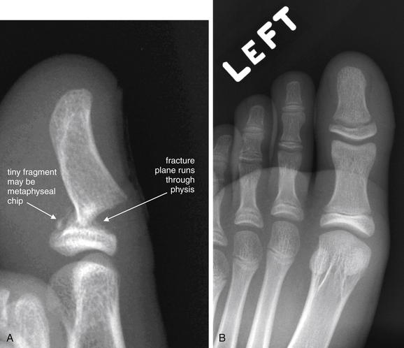
Figure 14-126 Salter-Harris II fracture of great toe.
This 12-year-old male sustained a great toe injury when an adult stepped on his foot. The patient had a subungual hematoma on examination. A, Lateral x-rays show a displaced fracture through the physis, with plantar angulation of the distal fragment. A tiny bone chip is visible, possibly representing part of the metaphysis. Note how normal the anterior–posterior view (B) is. If the separation of the physis is the only injury, this would be characterized as a Salter-Harris I injury. Involvement of the metaphysis makes this a Salter-Harris II fracture. However, the bottom line for the emergency physician should be that this is a displaced fracture through a growth plate and potentially an open fracture given the subungual hematoma. Immediate orthopedic consultation is appropriate. This patient underwent operative repair with pinning of the fracture and repair of the nail bed.
Muscle Injuries
Muscle injuries are not visible on x-ray, though in some cases they may be suspected based on patterns of bony injury. In general, these injuries do not require diagnostic imaging in the emergency department. When management requires specific diagnosis, MRI is the optimal imaging test because of its excellent soft-tissue contrast.
Neoplasms and Soft-Tissue Masses
Bony extremity tumors include primary bone malignancies such as osteosarcomas and Ewing sarcoma, as well as a variety of metastatic tumors, such as lung, breast, thyroid, testicular, kidney, and prostate. Multiple myeloma also causes lytic bone lesions often visible on x-ray. Figures 14-127 and 14-128 demonstrate bone abnormalities concerning for neoplasm. Pathologic fractures may also be seen at the site of a bone neoplasm, whether benign or malignant (see also Figure 14-38).
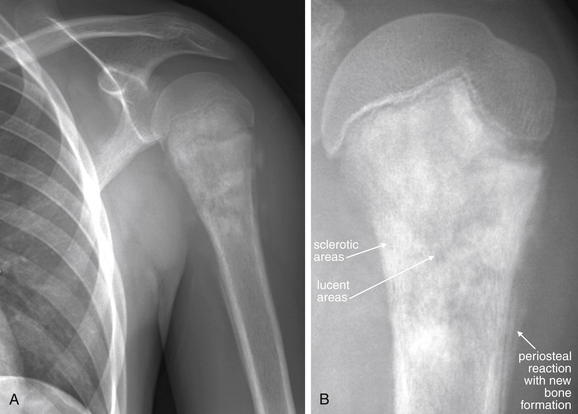
This 13-year-old male complained of 4-6 weeks of left shoulder pain, with no history of trauma. X-rays were obtained. A, Internal rotation, AP view. B, Close-up in external rotation. The proximal humerus shows both sclerotic (dense white) and lucent (black) areas with ill-defined margins. These extend from the physis to the metaphysis. Periosteal reaction is also present, with new bone formation occurring in the uplifted subperiosteal space—a finding called Codman’s triangle. These findings are extremely concerning for osteosarcoma in this age group. This was confirmed on bone biopsy. Bony pain without trauma in children should prompt evaluation for malignancy or bone infection. Immediate follow-up is needed for abnormal findings such as in this patient. Sadly, this patient already had lung metastases and died despite aggressive treatment.
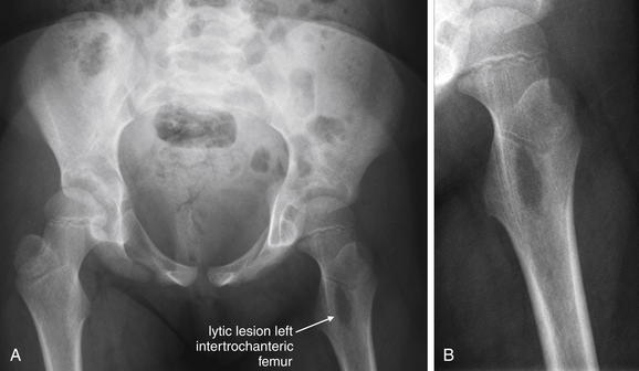
This 6-year-old female presented with left proximal femur pain for 5 days, with no history of trauma or fever. A, Anterior–posterior pelvis. B, Close-up. X-rays of the hip show a lytic lesion in the intertrochanteric left femur. No periosteal reaction is visible, which would be typical of some bony malignancies, such as osteosarcoma. Radiologists can generate a differential diagnosis for lesions such as this based on their appearance—this lesion was felt to be suspicious for Langerhans cell histiocytosis. However, infection or benign or malignant neoplasm is possible with lesions that have this appearance. Pathologic fracture through lytic bone lesions can occur spontaneously or with minor trauma. The emergency physician should recognize the general appearance of such lesions and understand the importance of timely follow-up. Spontaneous bony pain, particularly in children, can indicate neoplasm or infection. This patient underwent next-day magnetic resonance imaging showing a heterogeneous mass with cortical destruction and a soft-tissue component. Surgical excision was performed, and biopsy fortunately showed a benign fibroosseous lesion with multiple giant cells but no evidence of malignancy.
Soft-tissue masses do not routinely require emergency diagnostic imaging, although abscesses may masquerade as solid masses. Abscesses are usually readily identified by ultrasound when superficial; deeper collections may require CT for diagnosis. Solid soft-tissue masses can be extremely serious, including malignancies such as sarcomas. Although the workup can often be deferred to the outpatient setting, there may be patients whose follow-up cannot be assured and for whom a definitive diagnosis in the emergency department is preferred. MRI is the optimal imaging test for these patients. The ACR recommends x-rays in the initial evaluation of soft-tissue masses, while noting their limited utility and the possible need for advanced imaging such as MRI, regardless of x-ray results. X-rays may indicate an underlying bony lesion such as infection or bone neoplasm. X-ray findings of neoplasms can include lytic or sclerotic lesions, pathologic fractures, soft-tissue calcifications, and periosteal reaction.99,99a Detailed diagnostic imaging of extremity neoplasms is beyond the scope of this text.