Anesthetic Equipment
After completion of this chapter, the reader will be able to:
• Identify equipment that is used for anesthetic induction, endotracheal intubation, and anesthetic maintenance.
• Choose and prepare an appropriate endotracheal tube for a dog, cat, horse, or cow.
• List the reasons for and advantages of endotracheal intubation.
• Describe the four basic anesthetic machine systems, and identify the parts of each system.
• Describe the basic operation of an anesthetic machine.
• Trace the flow of oxygen through an anesthetic machine and patient breathing circuit for rebreathing and non-rebreathing systems.
• Describe the function and use of each component of an anesthetic machine, anesthetic masks, and anesthetic chambers.
• Explain the use of oxygen supply of the anesthetic machine, including safety concerns associated with compressed gas cylinders.
• Explain differences between a rebreathing and a non-rebreathing system with regard to equipment, gas flow, advantages, disadvantages, and indications for use.
• Identify the function and use of each component of commonly used rebreathing and non-rebreathing circuits.
• Differentiate between a precision and a nonprecision vaporizer, and recognize the rationale for using each.
• Compare and contrast vaporizer-out-of-circuit (VOC) and vaporizer-in-circuit (VIC) vaporizers in terms of setup, use, and agents administered in each of these systems.
• Identify factors that affect anesthetic vaporizer output.
• Explain the impact of oxygen flow rates on anesthetic concentration within the breathing circuit, changes in anesthetic depth, patient safety, and waste gas production.
• List oxygen flow rates for each common domestic species, breathing system, and period of an anesthetic event.
• Explain the advantages and disadvantages of closed and semiclosed rebreathing systems.
• Explain the procedure that should be followed to prepare an anesthetic machine for use.
• Describe the proper maintenance procedures for anesthetic machines and associated equipment.
Before the introduction of anesthetic machines, administration of inhalant anesthetics was a hazardous undertaking. Up until well into the twentieth century, liquid anesthetics such as ether or chloroform were administered using open systems (“open cone,” “open drop,” or chamber) (Figure 4-1). When these systems were used, control of anesthetic depth was crude at best and the anesthetist was not able to protect the airway, give supplemental oxygen, or assist ventilation. The development of modern anesthetic equipment greatly increased the safety and effectiveness of inhalation anesthesia by allowing the administration of precise concentrations of anesthetic and oxygen under controlled conditions. This chapter describes the purpose, function, use, and maintenance of equipment used to administer inhalant anesthetics including machines, vaporizers, breathing circuits, endotracheal tubes, masks, and chambers. As anesthetic accidents and complications are frequently associated with machine and equipment malfunctions and misuse, a comprehensive knowledge of and familiarity with this equipment is essential to the anesthetist’s ability to deliver anesthetic gases safey.
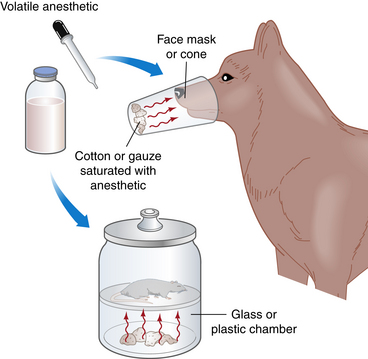
FIGURE 4-1 Open systems. With the open cone technique, a mask containing liquid anesthetic–soaked gauze is held over the patient’s muzzle until the patient is anesthetized. The position of the mask in relationship to the muzzle is altered to change anesthetic depth. The open drop technique is similar, but liquid anesthetic is dripped onto a cloth held over the patient’s nose and mouth. Very small patients are anesthetized by dripping liquid anesthetic onto a cloth placed inside a chamber.
ENDOTRACHEAL TUBES AND ASSOCIATED EQUIPMENT
An endotracheal tube (ET tube) is a flexible tube, placed inside the trachea of an anesthetized patient, that is used to transfer anesthetic gases directly from the anesthetic machine into the patient’s lungs, bypassing the oral and nasal cavities, pharynx, and larynx. ET tubes are commonly used for patients undergoing general anesthesia because they maintain an open airway; decrease anatomic dead space; allow precise administration of inhalant anesthetics and oxygen; prevent pulmonary aspiration of stomach contents, blood, and other material; enable rapid response to respiratory emergencies; and allow the anesthetist to accurately monitor and control patient respirations. Because of these benefits, many veterinarians use ET tubes for most or all patients, even if they are not receiving inhalant anesthetics.
ET tubes are available in several different types and materials and in a wide variety of diameters and lengths. Although the tubes are similar in basic design, this variety in size and type gives the anesthetist the ability to choose a tube uniquely suited to the needs of any particular patient.
There are two basic types of ET tubes. Murphy tubes (Figure 4-2, A, C, D, and E) have a beveled end and a side hole called the Murphy eye and may or may not have a cuff (a balloon-like structure on the patient end of the tube). Cole tubes (Figure 4-2, B) have no cuff or side hole but are designed with an abrupt decrease in diameter near the patient end of the tube. Cole tubes are used for species that have complete tracheal rings such as birds and some reptiles to prevent damage to the trachea that would be caused by a cuffed tube. A seal is created by seating the neck of the tube (the point of transition between the larger- and the smaller-diameter portions of the tube) at the tracheal opening.
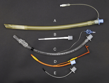
FIGURE 4-2 Endotracheal tube type, material, and size comparison. A, Cuffed 11-mm, silicone rubber Murphy tube. B, 2.5-mm Cole tube. C, Cuffed 8-mm polyvinyl chloride (PVC) Murphy tube. D, Cuffed 4-mm red rubber Murphy tube. E, Uncuffed 2 mm PVC Murphy tube.
ET tubes are made of polyvinyl chloride (PVC), red rubber, or silicone. PVC tubes (Figure 4-2, C and E) are transparent and are somewhat stiffer than other types. This stiffness minimizes the risk of tube collapse but increases the risk of trauma to tracheal mucosa during tube placement, when turning the patient, and during patient transfer. Red rubber tubes (Figure 4-2, D) are more flexible and less traumatic but have several disadvantages. They are more prone to kinking or collapsing, especially if small. They may absorb disinfectant solutions, resulting in irritation from contact with the patient’s oropharynx or trachea, and tend to dry and crack after prolonged use. Specialized rubber tubes, called spiral or anode tubes, contain a coil of metal or nylon embedded in the rubber designed to resist kinking or collapse from external pressure. Silicone tubes (Figure 4-2, A), although more expensive, combine strength with pliability and are consequently resistant to collapse and less irritating to tissues than either rubber or vinyl tubes.
ET tubes come in standard lengths. On most, with the exception of very small tubes, a scale printed on the side (Figure 4-3, F) marks the distance from the patient end in centimeters. Before the tube is placed, this scale can be used to estimate the appropriate distance to advance the tube.
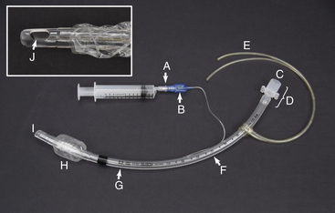
FIGURE 4-3 Endotracheal tube parts. A, Valve with syringe attached. B, Pilot balloon. C, Machine end. D, Connector. E, Tie. F, Measurement of length from the patient end (cm). G, Measurement of internal diameter (mm). H, Inflated cuff. I, Patient end. J, Murphy eye.
Tube size is most commonly expressed as the internal diameter (ID) in millimeters. The ID of each tube is written on its surface (Figure 4-3, G). ET tubes range in size from as small as 1 mm for exotic animals to 30 mm for mature large domestic animals. (See Chapters 8, 9, and 10 for common sizes used in the common domestic species).
Endotracheal Tube Parts
The patient end of the tube (Figure 4-3, I) is passed through the mouth or nose and into the trachea. The Murphy eye (Figure 4-3, J), if present, minimizes the risk of patient asphyxiation in the event that the end hole is blocked with mucous. The machine end (Figure 4-3, C) protrudes from the mouth or nose and is connected to the breathing circuit of the anesthetic machine via the connector (Figure 4-3, D). If present, the cuff (Figure 4-3, H) is inflated to create a seal between the tube and trachea. The cuff is connected via a small tube to a pilot balloon (Figure 4-3, B) and a valve (Figure 4-3, A) that is used to inflate the cuff. The valve opens to permit air to enter or exit the cuff when a syringe is seated firmly into the valve opening, and automatically closes when the syringe is removed. The pilot balloon allows the anesthetist to monitor cuff inflation visually or manually.
During intubation of mammals, use of a cuffed tube is strongly recommended for the following reasons:
1. The inflated cuff helps prevent leakage of air and gases around the tube and therefore reduces waste gas pollution in the operating room.
2. Use of a cuffed tube minimizes the risk of aspiration of blood, saliva, vomitus, and other material into the lungs.
3. Cuffed tubes prevent the animal from breathing room air, which may otherwise flow around the outside of the tube and dilute anesthetic gases. Adequate depth of anesthesia is difficult to maintain in animals breathing significant amounts of room air.
Despite these advantages, cuffed tubes should be used with caution, especially in small patients. The cuff of the tube may exert significant pressure on the tracheal mucosa and cause local inflammation or necrosis, particularly during long procedures, and in extreme cases can even cause tracheal rupture. Tubes without a cuff or with the cuff not inflated are often used in very small patients to minimize the risk of tracheal damage.
The placement and management of ET tubes is reviewed in detail in Chapters 8, Chapter 9, and Chapter 10; however, the following points should be noted:
• ET tubes should not bind during placement. Some materials, such as silicon, are naturally slippery, whereas others may require lubrication with water, patient saliva, or commercial water-soluble lubricant.
• When correctly used, ET tubes reduce dead space (see Chapter 8, p. 245). For this to be achieved, the ET tube should be no longer than the distance between the most rostral aspect of the mouth and the thoracic inlet. If longer, there are two possible risks. First, if the tube extends an excessive distance inside the trachea, the patient end may enter one main stem bronchus. Only one lung will be infused with oxygen and anesthetic gas, leading to hypoventilation, hypoxemia, and possibly difficulty keeping the patient anesthetized. Second, if the tube extends beyond the rostral aspect of the mouth, it will increase mechanical dead space, resulting in hypoventilation, especially in small patients. A guideline is that if the tube is more than 2.5 cm longer than the distance between the most rostral aspect of the mouth and the thoracic inlet, it is too long and should be cut shorter or replaced with a shorter tube.
• Special cautions must be observed when ET tubes are used in conjunction with laser surgery. Lasers create intense heat; in a high-oxygen environment such as the trachea, there is a risk of fire, and the ET tube may ignite. The anesthetist should use special laser-resistant tubes or adapt regular tubes by wrapping them with U.S. Food and Drug Administration (FDA)–approved materials. It may also be advisable to shield the tube with saline-soaked sponges and fill the cuff with saline instead of air.
Laryngoscopes
A laryngoscope is a device used to increase visibility of the larynx while placing an ET tube. Laryngoscopes have a handle, a blade, and a light source. The handle contains batteries to power the light source, the blade is used to depress the tongue and epiglottis, and the light source illuminates the throat (Figure 4-4). Small animal blades are available in many sizes ranging from 0 (small) to 5 (large). Custom large animal blades up to 18 inches in length are available for use in swine, small ruminants, camelids, and some exotics. Miller blades are straight (Figure 4-4, A and C), and McIntosh blades are curved (Figure 4-4, B and D). Laryngoscopes are often used in small ruminants, camelids, and swine and may be helpful in dogs and cats. They are not generally used in adult cattle, which are intubated by digital palpation, and horses, which are intubated blindly.
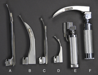
FIGURE 4-4 Laryngoscope handles and blades. A, Size 4 Miller blade. B, Size 4 McIntosh blade. C, Size 2 Miller blade. D, Size 1 McIntosh blade. E, Laryngoscope handle with size 00 Miller blade in unlocked position. F, Laryngoscope handle with size 3 McIntosh blade in locked position (note that the light turns on when the blade is locked).
MASKS
Anesthetic masks are cone-shaped devices used to administer oxygen and anesthetic gases to nonintubated patients via the nose and mouth (Figure 4-5). Masks may be used for both anesthetic induction and maintenance and are often used exclusively to administer anesthetic gases to very small patients, such as birds, rats, mice, and other laboratory and exotic species, in which intubation is difficult. They may also be used to administer pure oxygen to dyspneic, hypoxic, or other critically ill patients requiring supplemental oxygen.
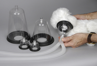
Masks are usually made of plastic or rubber and come in a variety of diameters and lengths. They have a rubber gasket over the open end, designed to create a seal around the patient’s muzzle.
Masks allow the anesthetist to rapidly administer oxygen to a fully conscious patient, sedated patient, or anesthetized patient that cannot be intubated or in which tube placement is delayed. Masks have several disadvantages, however. They do not maintain an open airway as ET tubes do, so airway obstruction is possible, particularly in brachycephalic breed animals and other patients prone to obstruction. There is no protection against pulmonary aspiration as there is with a tube, nor is the anesthetist able to ventilate the patient when necessary. The technique for mask induction is described and illustrated in Procedure 8-4.
ANESTHETIC CHAMBERS
Anesthetic chambers are clear, aquarium-like boxes used to induce general anesthesia in small patients that are feral, vicious, or intractable or cannot be handled without undue stress (Figure 4-6).
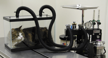
FIGURE 4-6 Anesthetic chamber attached to the corrugated breathing tubes of a semiclosed rebreathing circuit in place of the Y-piece.
They are often made of acrylic or Perspex, and have a removable top with two ports, one of which serves as a fresh gas source and the other which allows exit of waste gas.
Chambers are very useful for any patient that would be a danger to the anesthetist or itself if physically restrained. They prevent close monitoring of the patient, however, thus necessitating extreme care when patients are anesthetized using this method. The technique for chamber induction is described in Procedure 8-5.
ANESTHETIC MACHINES
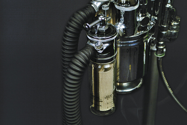
The primary function of any anesthetic machine is to deliver precise amounts of oxygen and volatile anesthetic under controlled conditions to patients undergoing general anesthesia. Over the course of a career, the veterinary technician will likely encounter a wide variety of machines in terms of brand, age, size, and sophistication (Figure 4-7). For example, machines in common use may be new or more than 30 years old. New anesthetic machines can cost from $2000 to $5000 for a basic model to more than $100,000 for a machine with state-of-the-art features such as built-in monitors and multiple vaporizers. Despite this diversity, all machines have the same basic design, which has changed surprisingly little over the past several decades, and principles of operation, which are universal. Underlying these similarities, however, is an inherent complexity, which may result in anesthetic accidents if not thoroughly understood. So the technician must devote much study and practice to achieve the mastery required to use an anesthetic machine safely.
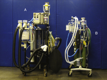
FIGURE 4-7 Comparison of large animal and small animal anesthetic machines. A, Large animal machine with precision isoflurane and sevoflurane vaporizers, a built-in ventilator, and a 30-L rebreathing bag. B, Small animal machine with an isoflurane precision vaporizer and a 5-L rebreathing bag. This picture illustrates differences in size and sophistication among anesthetic machines.
The basic principle of operation of any anesthetic machine can be described as follows: A liquid anesthetic (such as isoflurane or sevoflurane) is vaporized in a carrier gas (oxygen with or without nitrous oxide), which delivers the anesthetic to the patient via a breathing circuit. To achieve this result, the anesthetic machine and breathing circuit must perform several important functions:
• The carrier gases must be delivered at a controlled flow rate. Oxygen (O2) is the primary carrier gas used in all anesthetic machines. Nitrous oxide (N2O) is another carrier gas that was often used with oxygen to deliver older inhalant anesthetics, although it is seldom used with anesthetics in current use.
• A precise concentration of liquid inhalant anesthetic (most commonly isoflurane or sevoflurane) must be vaporized, mixed with the carrier gases, and delivered to the patient.
• Exhaled gases containing carbon dioxide (CO2) must be moved away from the patient and either removed through a scavenging system or recirculated to the patient. If the gases are recirculated, the machine must remove the CO2 before returning them to the patient.
Anesthetic machines are used not only for inhalation anesthesia but also as a means of delivering oxygen to critically ill patients. In these situations the vaporizer (i.e., the anesthetic source) is turned off, and the breathing circuit is used to deliver oxygen directly to the patient via an ET tube or a mask held over the patient’s muzzle.
COMPONENTS OF THE ANESTHETIC MACHINE
The anesthetic machine consists of four distinct systems that can best be understood by following the flow of gases from the oxygen source to the vaporizer, through the breathing circuit to the patient, and finally to the scavenging system (Figures 4-8 and 4-9).
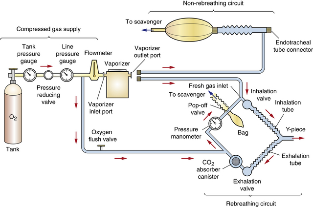
FIGURE 4-8 Schematic of an anesthetic machine without a common gas outlet, configured with a vaporizer-out-of-circuit (VOC) precision vaporizer. Both rebreathing and non-rebreathing circuits are illustrated.
• The compressed gas supply supplies carrier gases (oxygen and sometimes nitrous oxide) (Figure 4-10, A).
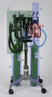
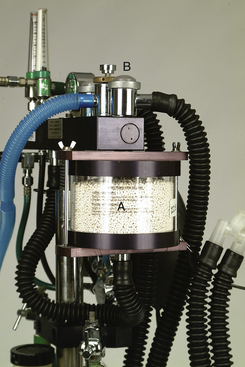
FIGURE 4-10 Anesthetic machine systems. A, Compressed gas supply: Note the two size E compressed gas oxygen cylinders beside the A’s at the bottom of this image. B, Precision anesthetic vaporizer. C, Breathing circuit. Note that the scavenging system (see Figure 4-11) is not visible in this view.
• The anesthetic vaporizer vaporizes liquid inhalant anesthetic and mixes it with the carrier gases. Vaporizers are classified as precision or nonprecision, and vaporizer-out-of-circuit (VOC) or vaporizer-in-circuit (VIC) (Figure 4-10, B).
• The breathing circuit conveys the carrier gases and inhalant anesthetic to the patient and removes exhaled carbon dioxide. Breathing circuits are classified as rebreathing circuits or non-rebreathing circuits (Figure 4-10, C).
• The scavenging system disposes of excess and waste anesthetic gases (Figure 4-11).
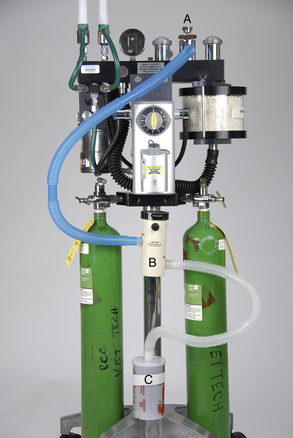
FIGURE 4-11 Scavenging system. The waste gas exits from the pop-off valve (A) of this rebreathing system (or the discharge hose of a non-rebreathing system), flows through the vacuum regulator (B), and finally flows either into a charcoal canister (C) or alternatively into an outlet pipe in the ceiling or wall.
The parts of each system are listed in Box 4-1.
Anesthetic machines can be configured in several ways. They may have either a precision or a nonprecision vaporizer and may be fitted with a rebreathing or non-rebreathing circuit. The most common machine configuration, used for all but the smallest patients, is one with a precision vaporizer and a rebreathing circuit (Figure 4-10). A machine configured with a precision vaporizer and non-rebreathing circuit is used for patients under 2.5 to 3 kg and may be used for patients up to 7 kg in body weight (Figure 4-12).
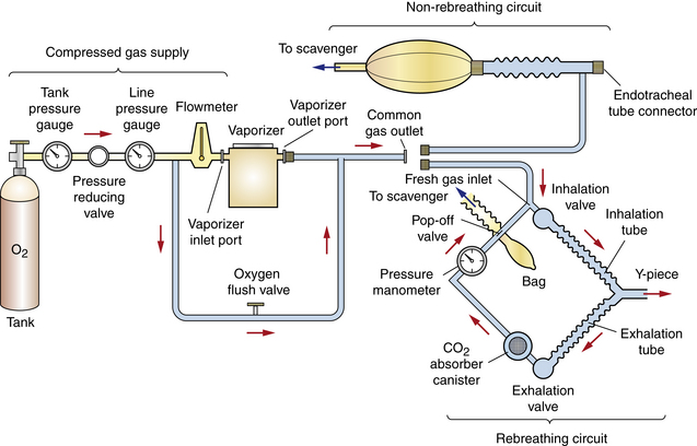
FIGURE 4-9 Schematic of an anesthetic machine with a common gas outlet, configured with a vaporizer-out-of-circuit (VOC) precision vaporizer. Both rebreathing and non-rebreathing circuits are illustrated.
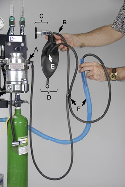
FIGURE 4-12 Parts of a non-rebreathing circuit. A, Outlet port of the vaporizer with keyed fitting. B, Fresh gas inlet. C, Connector with mask attached. D, Reservoir bag. E, Pressure relief valve. F, Scavenging hose.
Compressed Gas Supply
Oxygen is necessary to sustain normal cellular metabolism and must be continuously supplied to every patient throughout anesthesia. Room air has an oxygen concentration of about 21%. In a healthy, conscious patient breathing room air with 21% oxygen, the approximate concentration in the alveolus is 13%, in arterial blood 12%, in capillary blood at tissue level 5%, and in the tissues only 2%.
Anesthetized patients breathing room air often have lower tissue oxygen concentrations because most anesthetics decrease both the respiratory rate and tidal volume (VT). Consequently the total volume of inspired oxygen is lower. It is therefore desirable to increase the concentration of oxygen in inspired air to at least 30% to compensate for this decrease. Anesthetic machines are designed to provide up to 100% oxygen, thus fulfilling this requirement.
Note that oxygen has a second function. Not only does it meet metabolic requirements, but it also passes through the vaporizer and carries vaporized anesthetic to the patient. Therefore no anesthetic is delivered to the patient unless oxygen is present to act as a carrier gas.
Compressed Gas Cylinders
Compressed gas cylinders (also called “tanks”) contain a large volume of carrier gas in a highly pressurized state (as much as 2200 psi or 15,000 kilopascals [kPa]). This enables large amounts of gas to be stored in a space small enough to be of practical use. Oxygen, nitrous oxide, and medical air are three gases used for anesthesia that are stored in compressed gas cylinders. Nitrous oxide is a carrier gas that, although used in the past in conjunction with older inhalant anesthetics, is seldom used in the current practice of anesthesia. Although medical air is not commonly used in veterinary anesthesia, it is mixed with oxygen in human patients to provide an optimal concentration. Therefore when using a machine originally manufactured for human use, a medical air flow meter, yoke, and/or quick-release connector may be present. In contrast to nitrous oxide and medical air, oxygen is used for all anesthetic procedures involving inhalant anesthetics and therefore will be the focus of the discussion that follows.
Compressed gas cylinders may be either small (E tanks) (Figure 4-13, B) or large (H tanks) (Figure 4-13, A). E tanks are attached directly to the yoke of an anesthetic machine or may be stored on a cart when not in use (Figure 4-14). H tanks, which are considerably larger than E tanks, are usually stored on a cart or chained to the wall and attached to a machine remotely by a system of intermediate-pressure gas lines that carry gas to quick-release connectors throughout the hospital (Figure 4-15). Gas lines may take the form of flexible hose, or gas may be carried in pipes mounted within the ceiling or wall. Quick-release connectors join the gas line from the compressed supply to the machine (Figure 4-16). In many hospitals, H tanks are the primary source of oxygen and E tanks are used as a backup supply. In locations where piped-in gas is unavailable, E tanks are used as both the primary and the secondary supplies.
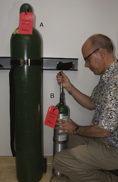
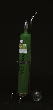
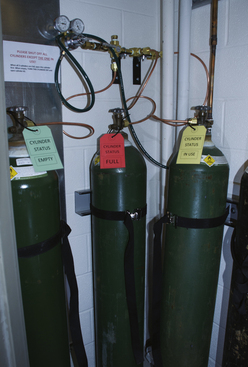
FIGURE 4-15 Bank of H tanks used as a primary oxygen supply for the entire hospital via intermediate-pressure gas lines hidden in the ceiling.
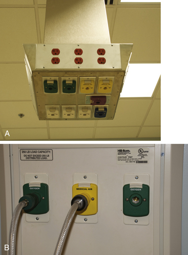
FIGURE 4-16 A, Ceiling drop with diameter-index safety system (DISS)outlets for oxygen (green), nitrous oxide (blue), medical air (yellow), and vacuum (white). B, Quick-release DISS connectors used to couple intermediate-pressure gas lines to the anesthetic machine. Note that the diameter of each outlet port type is unique to prevent attachment of the wrong connector.
The capacities of cylinders are given in Table 4-1. Cylinders often are owned by the company that supplies the oxygen but may be purchased by the user. In either case, empty cylinders are periodically picked up by the oxygen supplier, refilled, and returned to the user.
TABLE 4-1
Compressed Gas Cylinder Characteristics, Capacity, and Pressure
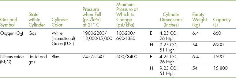
Modified from Tranquilli WJ, Thurmon JC, Grimm KA: Lumb and Jones’ veterinary anesthesia and analgesia, ed 4, Ames, Iowa, 2007, Blackwell.
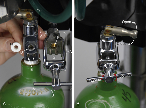
All compressed gas cylinders have a valve on the top to control the flow of gas. The valve on an H tank has a threaded outlet port through which the gas flows (Figure 4-17). In contrast, the valve on an E tank has three holes—one outlet port, and two pin index safety system holes (Figure 4-18). The outlet port is connected to a pressure-reducing valve (see Figures 4-17, B and 4-22, C) (directly in the case of an H tank or via the yoke in the case of an E tank), which reduces the outgoing pressure to a usable level before conveying it to the rest of the machine through intermediate-pressure gas lines.
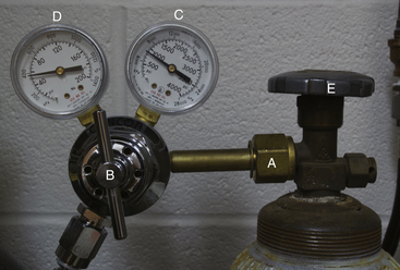
FIGURE 4-17 Size H compressed gas cylinder. A, Threaded outlet port. B, Pressure-reducing valve. C, Tank pressure gauge. D, Line pressure gauge. E, Knurled knob.
Use
It is vital that the anesthetist check both primary and secondary oxygen supplies at the beginning of the day to be sure they are turned on. A failure to do this may result in a patient not receiving oxygen, a dangerous error that, if not recognized, may be fatal. Because pressurized gas remains in the high- and intermediate-pressure lines even if the tank is turned off, a failure to turn a tank back on may easily go unnoticed unless double-checked by the technician.
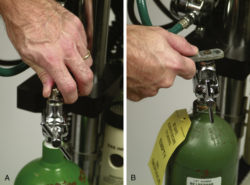
Oxygen flows from the outlet port of the valve when the stem is turned in a counterclockwise direction (i.e., to the left) (see Figure 4-18, B). The stem should be turned slowly until it is fully open. H-tank valve stems often have a knurled knob (see Figure 4-17, E) that is turned by hand. E-tank valve stems are opened and closed with a special wrench or via a lever that can be turned by hand (Figure 4-19). The flow stops when the valve stem is turned completely clockwise until firmly closed (i.e., to the right). The mnemonic “left loose, right tight” (loose meaning open and tight meaning closed) has been used by several generations of anesthesia students as an aid in remembering the direction to turn the stem. When opening and closing these valves, you should not have to use excessive force. Difficulty in turning the valve stem may indicate a malfunction. In this case the valve should be professionally serviced before use is continued.
After use, the outlet valve of each tank should be closed. Failure to turn off the gas valve can create a danger if anyone attempts to remove the tank while it is open, or over a long period it may result in leakage of gas from the tank.
Oxygen pressure remaining in the intermediate-pressure lines after the valve is closed (called line pressure) should be released by depressing the oxygen flush valve or by turning the flow meter to a high rate of flow until all the gas is vented. Failure to evacuate line pressure may give the anesthetist the false impression that the oxygen is turned on when in fact it is not. (Information on removing and replacing cylinders may be found in the section on anesthetic machine maintenance found on p. 131).
 TECHNICIAN NOTE
When handling compressed gas cylinders:
• Avoid contact with flames, sparks, or other sources of ignition.
• Turn the tank on only when it is attached to a yoke or pressure regulator.
• Store tanks only attached to a yoke, secured in a cart designed for this purpose, or chained to the wall.
• Never attempt to attach a tank to a yoke that does not fit, and never tamper with the safety system on a tank, line, or pressure-reducing valve.
Safety
There are four potential risks from compressed gas cylinders, as follows:
1. Both oxygen and nitrous oxide support combustion. Therefore contact with flames, sparks, and other sources of ignition must be avoided.
2. A forceful release of gas from an unprotected outlet port may tear the skin or injure an eye. To avoid this type of injury, turn the tank on only when it is attached to a yoke or pressure regulator. The only exception to this rule is when opening the valve to clean dust and dirt from the outlet port before attaching it to a machine or pressure regulator. In this case, turn the valve on slowly and only enough to expel the dirt from the port.
3. If a cylinder is dropped and the valve breaks off, the cylinder may cause serious personal injury! High-pressure gas exiting a cylinder through a broken valve will cause the cylinder to fly at high velocity in the opposite direction of the released gas, becoming in effect a “torpedo,” the force of which is sufficient to penetrate concrete and injure or kill anyone in its path. Therefore these tanks must be stored only attached to a yoke, secured in a cart designed for this purpose, or chained to the wall. Never drop compressed gas cylinders or leave them standing alone with no support or lying on their side.
4. If inadvertently attached to a valve, yoke, or hose intended for a different type of gas, the wrong gas will be delivered to a patient. For example, if a nitrous oxide cylinder were attached to an oxygen yoke, the patent would receive nitrous oxide instead of oxygen, resulting in asphyxiation. To safeguard against this, all compressed gas supplies have safety systems and features designed to prevent the wrong type of gas cylinder from being attached to the machine connections. First, all cylinders, flow meters, pressure-reducing valves, gas lines, and quick-release connectors are color-coded to prevent inadvertent use of an incorrect gas. Oxygen cylinders are green (United States) or white (Canada, Europe), nitrous oxide cylinders are blue, and medical air cylinders are yellow (United States) or white and black (Canada, Europe) (see Table 4-1). Carbon dioxide is designated by the color gray. Although not used for anesthesia, carbon dioxide is used as a euthanasia agent for specific applications such as meat packing plants and research facilities.
E-tank yokes are equipped with a pin-index safety system, which, unless tampered with, physically prevents the wrong gas from being connected to the yoke. For example, an oxygen cylinder cannot be put on a nitrous oxide yoke (Figure 4-20). H-tank pressure-reducing valves are threaded to accept only one gas. Quick-release connectors are protected with a diameter-index safety system (DISS). In this system, the diameter of the male and female parts of the connector is specific to one gas (see Figure 4-16). Attempting to defeat a safety system by removing the pins on a pin-index safety system of an E tank, stacking several washers in a yoke of a machine, or using a thread converter on an H tank will create a life-threatening situation. Never attempt to attach a tank that does not fit or to tamper with the safety system on a tank, line, or pressure-reducing valve.
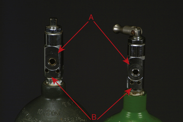
FIGURE 4-20 A, Outlet port. B, Pin-index safety system holes. Note that the pin holes on the carbon dioxide tank (left) are farther apart than the pin holes on the oxygen tank (right). The unique pin hole position for each gas prevents a tank containing the wrong gas from being attached to the yoke.
Alternate Oxygen Sources
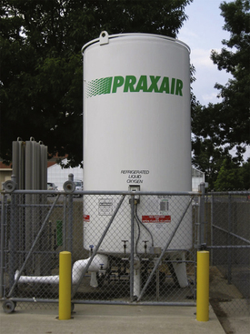
The technician may encounter some situations in which the primary oxygen supply is a bulk tank of liquid oxygen or an oxygen concentrator instead of compressed gas cylinders. This situation is likely to be encountered only in large hospitals.
A bulk tank contains a large quantity of oxygen in liquid form (Figure 4-21). An oxygen concentrator is a device that extracts oxygen from room air, concentrates it, and pressurizes it for medical use. As with any other primary supply, the technician must be sure that a secondary supply is available in the event of a failure of the primary source.
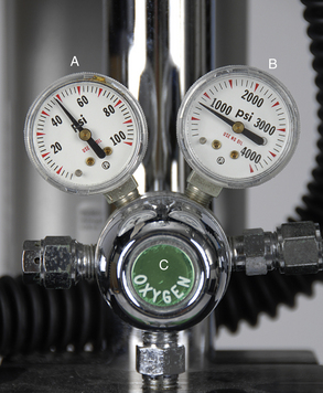
Tank Pressure Gauge
A tank pressure gauge is a device attached to the yoke of a machine, or the pressure regulator of an H tank, that indicates the pressure of gas remaining in a compressed gas cylinder measured in pounds per square inch (psi) in the United States or kilopascals in Europe and Canada (Figure 4-22, B and Figure 4-17, C). See Appendix E for a conversion formula from pounds per square inch to kilopascals.
Use
When the tank valve is opened, the gauge indicates the gas pressure inside the tank. This gauge must be checked before commencement of any procedure to ensure that enough gas remains in the tank to safely complete it. The pressure in a full oxygen tank is about 2200 psi (about 15,000 kPa). (Note that the pressures in a nitrous oxide tank are different and are discussed in Appendix B). As gas is used, the pressure in the tank will gradually fall, reaching zero when the tank is empty. The gauge also reads zero if the tank is not empty but is turned off and the remaining gas in the intermediate-pressure line has been evacuated (i.e., “bled off”) (see p. 108 for a description of this procedure). This gauge functions passively and therefore requires no action on the part of the anesthetist.
TECHNICIAN NOTE
The volume in liters (L) of oxygen present in a compressed gas cylinder can be calculated by multiplying the pressure (in psi) in an E tank by 0.3 or by multiplying the pressure in an H tank by 3.
The volume in liters (L) of oxygen present in an E tank can be calculated by multiplying the pressure (in psi) by 0.3 (see Table 4-1). For example, a full E tank, at a pressure of 2200 psi, contains about 660 L of oxygen (i.e., 0.3 × 2200 psi). A reading of 1100 psi indicates the tank is approximately half full and therefore contains approximately 330 L of oxygen. The volume in liters for the larger H tank can be calculated by multiplying the pressure (in psi) by 3. For example, a full H tank at a pressure of 2200 psi contains approximately 6600 L of oxygen (i.e., 3 × 2200 psi).
The volume of the oxygen in the tank indicates how much longer the tank can be used. For example, if the anesthetist selects an oxygen flow rate of 1 L per minute (L/min), a full E tank containing 660 L of oxygen will last approximately 11 hours (i.e., 660 minutes), whereas at a flow rate of 2 L/min the same full tank will last approximately 5.5 hours (i.e., 330 minutes). In contrast, a full H tank at a flow rate of 1 L/min contains enough oxygen to last 110 hours (6600 minutes).
Tanks should be marked “full,” “in service,” or “empty” to indicate their status (Figure 4-23), and a full backup tank must always be kept on the machine as a spare in case the primary tank runs out. The anesthetist may notice a considerable drop in pressure during a lengthy anesthetic procedure. If not detected in time, oxygen flow to the patient will cease, and this will put the patient in danger because veterinary anesthetic machines have no alarm to warn of inadequate flow. Therefore the anesthetist must periodically monitor the oxygen tank pressure gauge during each procedure and change the tank when the gauge indicates that the tank is close to empty. As an example, an E tank with 600 psi should give the anesthetist enough gas to last at least 1 hour, assuming that an oxygen flow of no more than 3 L/min is used and the oxygen flush valve is not activated frequently. In any case, a tank should be changed when the pressure drops below 500 psi (about 3400 kPa), indicating only 150 L of oxygen remaining in the tank.
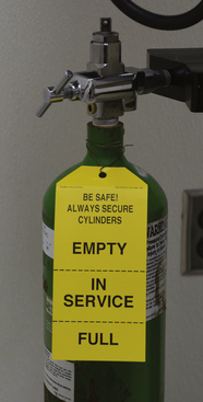
FIGURE 4-23 Label for compressed gas tanks. Current status of tank is shown by the wording at the bottom of the label. Label shown is from newly acquired tank and reads “FULL.” When the tank is first opened, the lower portion of the label is removed so that the remaining label reads “IN SERVICE.” When the tank is empty, the “IN SERVICE” stub is removed, leaving the label that reads “EMPTY.”
Pressure-Reducing Valve (Pressure Regulator)
Immediately after exiting the tank, the gas flows through a pressure-reducing valve (see Figures 4-17, B and 4-22, C), which is located near the tank pressure gauge, and then into an intermediate gas line. The pressure-reducing valve reduces the pressure of the gas to a constant safe operating pressure of 40 to 50 psi (about 275 to 345 kPa) regardless of the pressure changes within the tank. Pressure-reducing valves all look slightly different but are usually round and have a color-coded insignia on the outside to identify the gas flowing through them.
Line Pressure Gauge
The line pressure gauge indicates the pressure in the intermediate-pressure gas line between the pressure-reducing valve and the flow meters (see Figures 4-17, D and 4-22, A). It is not present on all machines, but when present is immediately downstream from the pressure-reducing valve.
Use
Like the tank pressure gauge and pressure-reducing valve, this gauge functions passively and so requires no action on the part of the anesthetist. When the oxygen is turned on, this gauge should read 40 to 50 psi. A pressure higher or lower than this indicates a malfunction of or a need to adjust the pressure-reducing valve. After the oxygen tank has been turned off, the line pressure gauge will continue to register line pressure until it is evacuated or “bled off.” This is accomplished by depressing the oxygen flush valve until the gauge reads 0 psi.
Flow Meter
After leaving the pressure-reducing valve, the carrier gas flows through an intermediate-pressure gas line into the flow meter. A flow meter is a vertical glass cylinder of graduated diameter with a valve attached to the bottom. When the valve knob is turned, gas enters the cylinder at the bottom and exits at the top. An indicator within the cylinder rises to indicate the gas flow expressed in liters of gas per minute (L/min) (Figure 4-24).
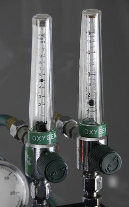
FIGURE 4-24 Oxygen flow meters with ball indicators. The flow meter on the left is adjusted to 0.5 L/min, and the flow meter on the right is adjusted to 1.5 L/min for a total oxygen flow of 2 L/min.
The flow meter also further reduces the pressure of the gas in the intermediate-pressure line from about 50 psi (about 345 kPa) to 15 psi (about 100 kPa). This pressure is only slightly above atmospheric pressure (about 14.7 psi) and is the optimum pressure for entry into the breathing circuit and ultimately the patient’s lungs.
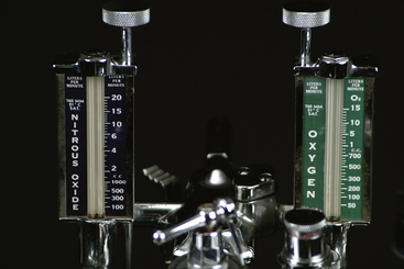
If a machine is set up to use both nitrous oxide and oxygen, there will be separate flow meters so that the flow rates of the two gases can be monitored and adjusted separately (Figure 4-25). To prevent the controls for oxygen and nitrous oxide from being confused, they are touch and profile coded (feel and look different), are color coded (green or white for oxygen, blue for nitrous oxide), and are labeled according to the gas they regulate. Some machines provide two flow meters for oxygen: one for flow rates greater than 1 L/min (coarse adjustment) and one to accurately adjust flow rates less than 1 L/min (fine adjustment).
Use
The flow meter is opened by turning the valve knob to the left, and the flow is then adjusted to the appropriate level for the patient (see p. 126 for a discussion of oxygen flow rates). All flow meters have a ball or rotor indicator that rises to a height proportional to the flow of gas. The scale on the cylinder indicates the gas flow. The meter is read at the center of a ball indicator or the top of a rotor indicator.
Flow meters must be treated gently when turning them off. The valve stem inside the flow meter is delicate and can be damaged by rough handling. Therefore when turning off a flow meter, turn clockwise just until the ball or rotor drops to 0 L/min. Even though the knob can still be turned, do not turn it any further to the right. Failure to turn off the flow meter may result in a sudden rush of air into the meter when the oxygen tank is opened, which may jam the rotor or ball at the top of the tube.
Oxygen Flush Valve
The oxygen flush valve is a button or lever that when activated rapidly delivers a large volume of pure oxygen at a flow rate of 35 to 75 L/min directly from the line exiting the pressure-reducing valve into the common gas outlet or into the breathing circuit of a rebreathing system, bypassing the anesthetic vaporizer and oxygen flow meters. This feature is used to rapidly fill a depleted reservoir bag. It is also used to deliver oxygen to a critically ill patient or at the end of the anesthetic period, to dilute out the anesthetic gas remaining in the circuit (see Figure 4-27, F).
Use
When activating the flush valve, press it briefly, using short bursts while watching the reservoir bag and pressure manometer to ensure that the bag does not overfill and the pressure in the circuit does not exceed 2 cm H2O. This will prevent pressurization of the breathing circuit, which could damage the patient’s lungs.
When using the oxygen flush valve to fill a collapsed reservoir bag, remember that the gas flowing into the breathing circuit from the valve will contain no inhalant anesthetic. Thus the gas delivered by this valve will dilute the concentration of inhalant anesthetic in the breathing circuit and the patient’s lungs.
When using it to deliver fresh oxygen to a critically ill patient or to flush inhalant anesthetic out of the circuit during anesthetic recovery or during a crisis, first turn off the vaporizer. Next force the gases out of the rebreathing bag and into the scavenging system using gentle hand pressure. Finally, press the valve to refill the bag with fresh oxygen.
Safety
As previously mentioned, the oxygen flush valve should be pressed briefly using only short bursts. Overfilling the bag has the potential of damaging the patient’s lungs because of a buildup of pressure. Some anesthetic machines are configured such that the oxygen flush valve discharges into the common gas outlet instead of the rebreathing circuit. In these cases the oxygen flush valve must not be used with a non-rebreathing system attached because a high flow rate of oxygen into this type of circuit can seriously damage the animal’s lungs.
Anesthetic Vaporizer
After exiting the flow meter, oxygen enters the vaporizer through the inlet port (see Figure 4-27, A). The function of the vaporizer is to convert a liquid anesthetic such as isoflurane or sevoflurane to a gaseous state and to add controlled amounts of this vaporized anesthetic to the carrier gases (O2 and N2O if used). After exiting the vaporizer through the outlet port, the oxygen and anesthetic mixture (known as fresh gas) enters the breathing circuit through a connection referred to as the fresh gas inlet. Most vaporizers are designed for use with only one specific anesthetic agent, which is purchased in liquid form and poured into the vaporizer.
The vaporized anesthetic can exit the vaporizer only by traveling in carrier gas, which transports it from the vaporizer into the breathing circuit. In other words, no anesthetic is delivered to the patient if the flow meter reads zero, because there is no flow of carrier gas to deliver the anesthetic.
Most newer vaporizers are classified as variable-bypass, flow-over. This is because they regulate the anesthetic output by routing a portion of the carrier gas through the vaporization chamber where the liquid anesthetic is located, while the remainder of the carrier gas bypasses the vaporization chamber. The portion of the carrier gas that enters the chamber flows over the surface of the liquid anesthetic and picks up vaporized anesthetic. So the more carrier gas that is routed through the chamber, the higher the concentration of the anesthetic delivered to the patient.
Types of Anesthetic Vaporizers
Anesthetic vaporizers are classified as either precision or nonprecision. This differentiation separates those that allow precise control of the amount of anesthetic delivered to the patient (expressed as the percent of the total gases exiting the vaporizer) from those that allow only estimation of the amount delivered. Nonprecision vaporizers (Figure 4-26) were used in the past to deliver low–vapor pressure anesthetics—such as methoxyflurane—which are no longer available.
Although nonprecision vaporizers can be used to deliver isoflurane or sevoflurane, as long as specific procedures are carefully followed, this practice is uncommon. In contrast, precision vaporizers (Figure 4-27) are used to deliver all commonly used liquid anesthetics including isoflurane, sevoflurane, and desflurane, and so are the main type the technician is likely to encounter in clinical practice. Therefore the discussion that follows refers specifically to precision vaporizers. In the event that the technician is asked to operate a nonprecision vaporizer, more information on their use can be found in Appendix C.
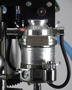
FIGURE 4-27 Precision anesthetic vaporizer for isoflurane set on 2%. A, Inlet port with keyed fitting leading from the flow meters. B, Outlet port with keyed fitting leading to the fresh gas inlet or common gas outlet. C, Safety lock. D, Indicator window. E, Fill port. F, Oxygen flush valve (part of the compressed gas supply).
The commonly used liquid anesthetics (isoflurane, sevoflurane, and desflurane) are classified as high–vapor pressure liquids. The designation “high vapor pressure” means that these anesthetics readily evaporate and may reach concentrations of 30% or greater within the anesthetic circuit if the amount of vapor being delivered to the breathing circuit is not controlled. Because the maximum useful concentration for isoflurane and sevoflurane is 5% and 8%, respectively, uncontrolled delivery of anesthetic vapor will result in excessively high levels that could be dangerous for the patient. It is therefore necessary to use a precision vaporizer to deliver these agents, affording the anesthetist more exact control of the anesthetic concentration in the circuit.
VOC versus VIC
The abbreviations VOC and VIC are used to describe two different ways anesthetic machines are configured based on the location of the vaporizer in relation to the breathing circuit. The letters VOC are an abbreviation for vaporizer-out-of-circuit (Figure 4-28, A) and indicate that the vaporizer is not located within the breathing circuit. In this case, oxygen from the flow meters flows into the vaporizer before entering the breathing circuit. Precision vaporizers are positioned in a VOC configuration.
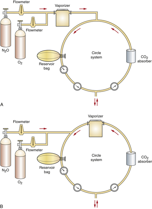
FIGURE 4-28 Schematic representation of vaporizer-out-of-circuit (VOC) versus vaporizer-in-circuit (VIC) configurations. A, VOC. B, VIC. (From Warren RG: Small animal anesthesia, St Louis, 1983, Mosby.)
In contrast, the letters VIC are an abbreviation for vaporizer-in-circuit (Figure 4-28, B). In this type of machine, carrier gases enter the breathing circuit directly from the flow meter without first entering the vaporizer. Instead, the vaporizer is located in the breathing circuit most often between the expiratory breathing tube and the expiratory unidirectional valve. Exhaled gases enter the vaporizer each time the patient breathes. Nonprecision vaporizers (e.g., the Ohio No. 8 or Stephens vaporizer) are positioned this way.
The location in which the vaporizer may be placed in relationship to the breathing circuit (VOC versus VIC) is governed by the resistance to the flow of gases through it. This is because patient respiratory drive during normal breathing is the force that moves gases around the breathing circuit. When resistance to gas flow is high, as is the case with precision vaporizers, respiratory drive is insufficient to push gases through the vaporizer. Consequently, precision vaporizers must be placed outside the breathing circuit. In contrast, nonprecision vaporizers offer little resistance to gas flow and therefore can safely be placed in the breathing circuit.
Factors Affecting Vaporizer Output
The concentration of anesthetic delivered by any vaporizer depends not only on the vaporizer setting but also on a variety of other factors including temperature, carrier gas flow rate, back pressure, barometric pressure, and respiratory rate and depth. Newer precision vaporizers are compensated and deliver a precise concentration independent of each of these factors with relatively little error or variation. However, older precision vaporizers and nonprecision vaporizers such as the Ohio No. 8 or Stephens vaporizer do not automatically compensate for these factors. Regardless of the type of vaporizer the anesthetist is using, a complete knowledge of proper use requires an understanding of the potential effect of each of these factors on vaporizer output.
Temperature
Volatile anesthetics, like all liquids, vaporize more readily at high temperatures than at low temperatures. Vaporization directly affects vaporizer output. If a vaporizer is not temperature compensated, vaporization will vary with changes in ambient (room) temperature, because room temperature affects the temperature of the anesthetic. For example, if a noncompensated vaporizer is used in a cold room, vaporization of the gas decreases and the anesthetic output is lower than that indicated on the dial. Conversely, in a warm room the output is greater than the dial setting.
The temperature of the anesthetic is also affected by carrier gas flow. This is because gas exiting a compressed gas cylinder is cold. At high carrier gas flow rates, the temperature of the liquid anesthetic falls, leading to decreased vaporization and lower anesthetic output than that indicated on the dial when a noncompensated vaporizer is used.
Most recently manufactured precision vaporizers are temperature compensated. Older models that are not temperature compensated include an internal thermometer and temperature adjustment scale that the anesthetist can use to adjust the vaporizer setting as needed to compensate for temperature changes.
Carrier Gas Flow Rate
The amount of carrier gas that flows through the vaporization chamber (primarily controlled by the vaporizer dial setting) determines anesthetic output. In a vaporizer that is not flow compensated, flow through the chamber is also affected by the carrier gas flow rate (determined by the flow meter setting). Higher flow meter settings result in increased flow through the chamber, and low settings result in decreased flow through the chamber. For example, when a non–flow-compensated vaporizer is used, output is higher at a flow meter setting of 3 L/min than at a flow meter setting of 500 mL/min.
Most modern precision vaporizers compensate for carrier gas flow and will deliver the amount of anesthetic indicated on the dial over a wide range of oxygen flow rates. Even in a flow-compensated vaporizer, compensation is not unlimited, however. Flows that are very high (i.e., in excess of 10 L/min) or very low (i.e., below 250 mL/min) may affect the output of flow-compensated vaporizers. Consequently, the vaporizer setting will not accurately reflect the concentration of anesthetic released at these extreme flow rates.
In precision vaporizers, whether compensated or noncompensated, carrier gas flow rate also influences the concentration of the anesthetic in the breathing circuit (and consequently in the air that the patient breathes). An oxygen flow rate that approaches the patient’s respiratory minute volume (RMV) (the total amount of gas a patient inhales or exhales in 1 minute) will produce a concentration in the circuit close to the dialed setting. At a lower flow rate, although the anesthetic concentration in the carrier gas delivered to the circuit does not change, the total amount delivered to the patient is lower, because as anesthetic is absorbed in the patient’s lungs and diluted by expired gases, the concentration within the circuit decreases. For example, if a 20-kg dog is connected to an anesthetic machine with an oxygen flow rate of 200 mL/kg/min (in this case, 4 L/min) and a vaporizer setting of 2%, the actual concentration of anesthetic being inhaled by the animal is close to 2%. If the oxygen flow rate is reduced to 100 mL/kg/min (in this case, 2 L/min), then to 50 mL/kg/min (1 L/min), and finally to 10 mL/kg/min (200 mL/min), the percent concentration of anesthetic in the circuit may drop to 1.8%, 1.2%, and 0.8%, respectively. In each case the vaporizer is delivering a 2% concentration to the circuit, but the concentration within the circuit varies as a result of dilution and absorption. This is why precision vaporizer settings may need to be increased if low oxygen flow rates are used (Box 4-2).
Respiratory Rate and Depth
If the anesthetist has occasion to use a VIC nonprecision vaporizer, he or she must be aware that respiratory rate and depth will also affect anesthetic delivery. This is because the respiratory rate and effort affect the flow of carrier gas through the vaporization chamber of a VIC nonprecision vaporizer. Consequently, high and low respiratory rates and depths will have the same effect on vaporizer output as high and low carrier gas flow. This is not an issue with VOC precision vaporizers because in this circumstance the patient’s respiratory drive has no influence on the amount of carrier gas passing through the vaporization chamber.
Back Pressure
Back pressure refers to an increase in pressure at the vaporizer outlet port caused by manual ventilation (bagging) or activation of the oxygen flush valve. A vaporizer that is not back pressure compensated will deliver more anesthetic under these circumstances. Most precision vaporizers are pressure compensated so that bagging or flush valve activation does not affect the amount of anesthetic released.
Use: Each precision vaporizer is designed to be used with a specific inhalant anesthetic such as sevoflurane, isoflurane, halothane, or desflurane and is color-coded (purple, isoflurane; yellow, sevoflurane; red, halothane; and blue, desflurane).
The vaporizer is turned on by depressing the safety lock and turning the dial to the desired level. The safety lock is present as a lever on some vaporizers and is incorporated into the dial on others (Figure 4-29). Inhalant anesthetic levels are measured in percent concentration. For common domestic species, the induction rate of isoflurane is approximately 3% to 5%. The maintenance rate is about 1.5% to 2.5%. The induction rate of sevoflurane is approximately 4% to 6%, and the maintenance rate is about 2.5% to 4%. The induction rate of desflurane is approximately 10% to 15%. The maintenance rate is about 8% to 12%. Patients should receive rates in the lower end of these ranges if preanesthetic medications have been administered.
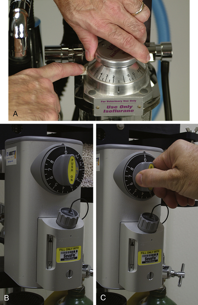
FIGURE 4-29 A, Tec 3 vaporizer. The dial lock (white lever) must be pressed down to turn the vaporizer on. B, Penlon Sigma Delta vaporizer. The dial must be pressed in to turn the vaporizer on. C, Vaporizer with the dial unlocked.
The dial of a precision vaporizer (see Figure 4-27) is graduated in percent concentration (e.g., 1%, 2%). Throughout any anesthetic procedure, the anesthetist must control the amount of inhalant anesthetic delivered to the patient by periodically adjusting the vaporizer dial. Appropriate and safe use of the vaporizer requires knowledge, experience, and detailed observation. Specifics regarding safe use of the vaporizer are discussed in detail in Chapters 8, 9, and 10.
Vaporizers must be checked before each procedure to make sure that enough anesthetic remains in the vaporization chamber. Most vaporizers have an indicator window at their base that allows the technician to inspect the amount of liquid anesthetic remaining. In order for the vaporizer to function properly, the liquid anesthetic level must be between the upper and lower lines of the window (Figure 4-30). The vaporizer should be refilled as needed but should be kept at least half full at all times. Overfilling a vaporizer will result in anesthetic overdose, and underfilling will result in an inability to keep the patient anesthetized.
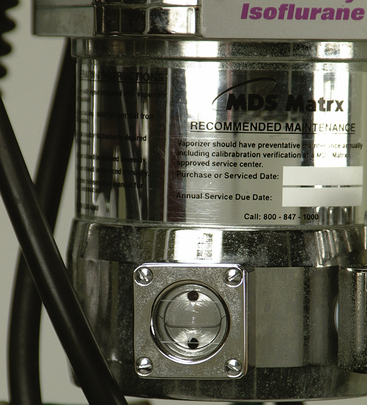
FIGURE 4-30 The indicator window of an anesthetic vaporizer. The level of the liquid anesthetic must be kept between the upper and lower lines.
TECHNICIAN NOTE
Vaporizers must be checked before each procedure to make sure the liquid anesthetic level is between the upper and lower lines of the indicator window. The vaporizer should be refilled as needed but should be kept at least half full at all times.
Safety: Vaporizers are subject to leakage if the anesthetic machine is tipped over or shaken vigorously. Under these circumstances, liquid anesthetic enters bypass channels of the vaporizer, and a potentially lethal dose of anesthetic may be delivered to the next patient. If an anesthetic machine is tipped or shaken, the anesthetic leak can be remedied by running oxygen through the machine at the maximum flow rate (with the vaporizer dial turned off) for 15 minutes. Emptying anesthetic machine vaporizers before transport is the best way to avoid this problem.
TECHNICIAN NOTE
If a bottle of liquid inhalant anesthetic accidentally breaks, vacate the room immediately and allow the room to air out until the anesthetic is completely evaporated and evacuated from the room.
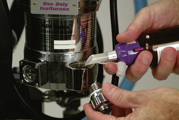
Volatile anesthetics readily evaporate when exposed to air. Therefore precautions must be taken to avoid inhaling the gas. First, take care not to drop or break the bottle. When refilling the vaporizer, make sure other personnel are not in the immediate vicinity, place a scavenging hose near the bottle while it is open to evacuate evaporated gas, cap the bottle promptly when finished, and close the vaporizer fill chamber immediately after filling. A pouring nozzle designed for use with these bottles is a valuable aid in preventing spills (Figure 4-31).
Vaporizer Inlet Port
The vaporizer inlet port is the point where oxygen and any other carrier gases enter the vaporizer from the flow meters (see Figure 4-27, A).
Use
The vaporizer inlet port is connected to the flow meters by a hose with a female keyed connector. This keyed connector prevents the operator from inadvertently attaching the outlet hose to the inlet port. Check that this connector is securely attached to the vaporizer before commencement of any procedure.
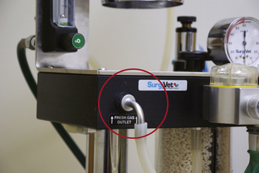
Vaporizer Outlet Port and Common Gas Outlet (Fresh Gas Outlet)
Both the vaporizer outlet port and the common gas outlet are fittings to which a hose connects. The vaporizer outlet port (see Figure 4-27, B) is the point where the oxygen, inhalant anesthetic, and N2O (if used) exit the vaporizer on the way to the breathing circuit. On some machines this port connects directly to the breathing circuit via a hose. On other machines it connects instead to the common gas outlet. The common gas outlet (Figure 4-32) then connects directly to the breathing circuit via a second hose. So on a machine with a common gas outlet, there are two lengths of hose between the vaporizer outlet port and the breathing circuit instead of one (see Figure 4-9).
Use
The vaporizer outlet port is connected to the common gas outlet or directly to the breathing circuit by a hose with a male keyed connector. This keyed connector prevents the operator from inadvertently attaching the inlet hose to the outlet port. It is important to check that this fitting is securely attached to the vaporizer before the commencement of any procedure.
Safety: When a non-rebreathing circuit on a machine without a separate common gas outlet is used, the male keyed connector of the rebreathing circuit is removed from the outlet port and the male keyed connector for the non-rebreathing circuit is attached to the vaporizer outlet port (see Figure 4-8) in its place. When a machine with a separate common gas outlet is used, the connector for the non-rebreathing circuit is attached to the common gas outlet instead. Regardless of which type you are using, after any procedure in which a non-rebreathing circuit is used, the connector of the rebreathing circuit must be reattached to the outlet port or common gas outlet before the next patient is anesthetized. It may, however, be inadvertently left unattached. When this happens, anesthetic gas will discharge into the room instead of into the circuit. This will result in an inability to keep the patient anesthetized and exposure of personnel to anesthetic gas. Checking the machine for leaks before each procedure can prevent this error.
TECHNICIAN NOTE
After use of a non-rebreathing circuit, the connector of the rebreathing circuit must be reattached to the outlet port or common gas outlet before the next patient is anesthetized. A failure to do this results in an inability to keep the patient anesthetized and exposure of personnel to anesthetic gas.
Breathing Circuit
The breathing circuit consists of a group of components that carry anesthetic and oxygen from the fresh gas inlet to the patient and convey expired gases away from the patient. The breathing circuit may be incorporated into the anesthetic machine (as is the case with a rebreathing system), or it may be a separate unit (as is the case with a non-rebreathing system).
REBREATHING SYSTEMS
A rebreathing system is an anesthetic machine fitted with a rebreathing circuit. Rebreathing systems are also called circle systems because exhaled gases minus carbon dioxide are recirculated and rebreathed by the patient, along with variable amounts of fresh oxygen and anesthetic. These systems are appropriate for almost all patients except those that are very small (under 2.5 to 3 kg in body weight).
When a rebreathing system is used, the gases exhaled by the patient travel through the expiratory breathing tube and the expiratory unidirectional valve then enter the CO2 absorber canister. They are then directed past the reservoir bag, pop-off valve, and pressure manometer and back toward the patient through the inspiratory unidirectional valve and inspiratory breathing tube. Exhaled gases include O2, anesthetic vapor, CO2, nitrogen, water vapor, and nitrous oxide (if used). Fresh oxygen and anesthetic enter the circuit from the fresh gas inlet and mix with the patient’s exhaled gases. The flow of gas through the anesthetic machine therefore is circular (inspiratory unidirectional valve, inspiratory tube, animal, expiratory tube, expiratory unidirectional valve, carbon dioxide canister, past the reservoir bag, pop-off valve, and pressure manometer, and back to the inspiratory unidirectional valve) (see Figure 4-8). When correctly adjusted, the flow meters, vaporizer, reservoir bag, and pop-off valve work in concert to maintain a constant flow of gas to the patient.
Rebreathing systems are further subdivided into closed rebreathing systems and semiclosed rebreathing systems. The main difference between these systems lies in the amount of carrier gas that is delivered to the breathing circuit (the flow rate) and the position of the pop-off valve. A closed rebreathing system (also called a total rebreathing system) is one in which the pop-off valve is kept nearly or completely closed and the flow of oxygen is relatively low, providing only the volume necessary to meet the patient’s metabolic needs. When the system is operating optimally, it is not necessary to vent gases from the circuit because the same volume of gas is added to the circuit as is consumed by the patient. In reality, however, this delicate balance of input and consumption is difficult to achieve and requires constant monitoring and adjustment. For this reason, closed systems are seldom used in practice with the exception of large animal anesthesia.
In contrast, a semiclosed rebreathing system (also called a partial rebreathing system) is one in which the pop-off valve is positioned partially open, and more oxygen is added than the patient requires. In this system, a portion of the gases is recirculated, but the amount beyond the volume that is used by the patient exits through the pop-off valve into the scavenging system. This type of system is relatively easy to use and meets the needs of the majority of patients. For this reason it is the most common machine configuration used in clinical practice.
Rebreathing Circuits
A rebreathing circuit consists of the following parts:
• Unidirectional (or one-way) valves
• Pop-off (or pressure relief) valve
A non-rebreathing circuit is less complex and is discussed in the section beginning on p. 122.
Fresh Gas Inlet
The fresh gas inlet is the point at which the carrier and anesthetic gases enter the breathing circuit. This inlet is usually located near the inspiratory unidirectional valve. The vaporizer outlet port or common gas outlet and the fresh gas inlet are connected by a hose (which is often black or clear) (see Figure 4-27, B).
Unidirectional Valves
The two unidirectional valves (Figure 4-33, A and C) control the direction of gas flow through the rebreathing circuit as the patient breathes. The inspiratory (inhalation) unidirectional valve is the attachment point for the inspiratory breathing tube, and the expiratory (exhalation) unidirectional valve is the attachment point for the expiratory breathing tube. The valves are located inside a housing with a clear, plastic dome on top that allows the anesthetist to observe the action of the valves, which open and close as the patient breathes to allow anesthetic gases to flow past. Sometimes, when the velocity of the gas is very slow, they “flutter” in response to gas flow—thus the alternative name “flutter valves.”
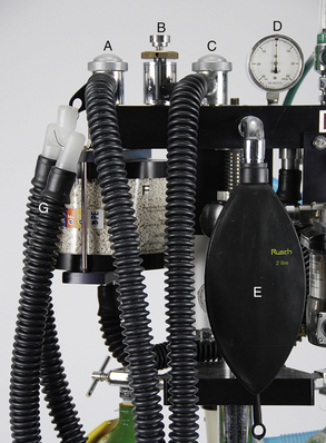
FIGURE 4-33 Parts of a rebreathing circuit. A, Exhalation unidirectional valve. B, Pop-off valve. C, Inhalation unidirectional valve. D, Pressure manometer. E, 2 liter reservoir bag. F, Carbon dioxide absorber canister. G, Small animal corrugated breathing tubes.
When the patient inhales, the inspiratory valve opens, allowing the oxygen and anesthetic gas to enter the inspiratory breathing tube and travel toward the patient. The gases then pass through the Y-piece and into the ET tube or mask. On reaching the patient’s lungs, oxygen and anesthetic molecules are absorbed and enter the bloodstream. At the same time, carbon dioxide and anesthetic molecules are released from the bloodstream, enter the alveoli, and are exhaled on the next breath.
Exhaled gases travel through the ET tube or mask and the Y-piece, enter the expiratory breathing tube, pass through the expiratory valve, and pass directly into the carbon dioxide absorber canister (Figure 4-34). This ensures that carbon dioxide is removed from the expired gas before the expired gas returns to the patient. The unidirectional valves thus cause the gases to travel a one-way modified circular path through the breathing circuit.
Use
The unidirectional valves function passively as the patient breathes and so require no action on the part of the anesthetist. These valves may be used to monitor patient respiratory rate and depth, and as an aid to check for proper placement of the ET tube. If the tube is not properly placed, the valves will move sluggishly or not at all despite normal respiratory volume and rate.
Pop-off Valve
The pop-off valve (also known as the pressure relief valve, exhaust valve, adjustable pressure limiting [APL] valve, or overflow valve) is the point of exit of anesthetic gases from the breathing circuit (see Figure 4-33, B). Pop-off valves have differing appearances but in all cases have a knob that can be turned to open or close them.
The main function of the pop-off valve is to allow excess carrier and anesthetic gases to exit from the breathing circuit and enter the scavenging system. By venting excess gas, the pop-off valve prevents the buildup of excessive pressure or volume of gases within the circuit. If allowed to occur, this excess pressure could damage the animal’s lungs by causing the alveoli to overdistend and rupture. Excess intrathoracic pressure also dramatically decreases return of blood to the heart, resulting in severely decreased cardiac output.
Use: In a similar way to a water tap, the pop-off valve can be set anywhere from fully closed to fully open, to allow varying amounts of gas to exit from the system and to maintain optimum volume in the reservoir bag. When fully open, it releases when the gas pressure in the circuit exceeds 0.5 to 1 cm of water. As the valve is tightened, more pressure is required for release.
When a semiclosed rebreathing system is used, the valve is kept partially open when the patient is spontaneously breathing. It is closed only when providing manual ventilation so that gases may be forced into the patient’s lungs using hand pressure. Between each breath provided by manual ventilation, it must be opened again to allow the escape of gases. This rule does not apply to use of a closed rebreathing system. (See Appendix D.)
TECHNICIAN NOTE
When manual ventilation is provided, the pop-off valve is closed before the bag is pressed. Between each breath, the pop-off valve must be opened again to allow the escape of gases.
Note that most pop-off valves can be closed only by turning the ring clockwise and opened only by turning it counterclockwise (Figure 4-35, A). The pop-off valve on some machines may be closed either by turning it as with other valves or by pressing firmly on the top. It is opened again by releasing pressure (Figure 4-35, B).
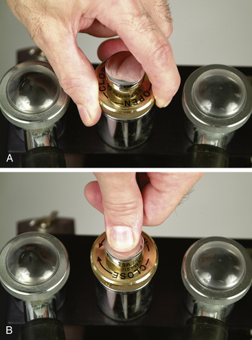
FIGURE 4-35 A, The pop-off valve on any machine can be closed by turning it clockwise, and opened by turning it counterclockwise. B, On some machines the pop-off valve can also be closed by pressing it firmly, and opened by releasing pressure.
The pop-off valve should be checked for proper operation and adjusted before commencement of any procedure. This should be done at the beginning of every day as a part of the low-pressure system leak test (see Procedure 13-1). It should also be checked periodically during the anesthetic procedure to maintain optimum gas volume within the circuit as indicated by the size of the reservoir bag.
The flow meter setting, the size of the rebreathing bag, and the position of the pop-off valve (open or closed) are related in the following way. The flow meter setting determines the rate at which gas enters the breathing circuit, and the pop-off valve setting determines the rate at which gas leaves the breathing circuit. The size of the bag reflects the net volume of gas in the breathing circuit at any given time. So by adjusting the carrier gas flow rate and pop-off valve setting, the anesthetist can keep the reservoir bag optimally inflated but not pressurized.
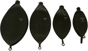
Reservoir Bag
The reservoir bag (also called the rebreathing bag) is a rubber bag, often black or green (see Figure 4-33, E), which serves a number of functions, including the following:
• It serves as a flexible storage reservoir. Because the breathing circuit is essentially a system of tubes and parts with a fixed volume, a space is necessary to accept expired air and provide air needed to fill the lungs during inspiration.
• It allows the anesthetist to observe the animal’s respirations. The bag expands as the patient exhales and contracts as the patient inhales. Both the respiratory rate and the respiratory depth can be determined by observing movement of the bag. A lack of movement of the bag indicates apnea, a disconnected Y-piece, or blockage of the airway. Inadequate movement indicates a leak in the system, a partial airway blockage, or a decreased VT. Either situation will alert the anesthetist to a need for intervention.
• It may be used to confirm proper ET tube placement. Movement of the bag in concert with patient respirations indicates that the ET tube is correctly placed within the trachea.
• It allows delivery of anesthetic gases to the patient. By application of light pressure to the bag (also known as manual ventilation or bagging), oxygen with or without anesthetic gas can be forced into the patient’s lungs. Manual ventilation is used for a variety of purposes including management of apnea, prevention of atelectasis, and provision of ventilation to patients undergoing any surgical procedure in which the chest cavity is open and to patients given neuromuscular blockers.
There are three reasons why bagging is beneficial for all anesthetized patients:
1. A condition known as atelectasis occurs to some degree in many anesthetized patients and compromises gas exchange. Bagging helps to reinflate the collapsed alveoli. Many experts recommend bagging all anesthetized patients every 5 to 10 minutes to gently inflate the lungs with fresh oxygen and anesthetic. Use of this technique is further described in Chapter 6.
2. Most anesthetics depress respiratory drive and decrease VT to as little as 50% of the volume seen in a normal, awake patient. This may lead to hypercarbia and hypoxemia. Bagging forces fresh gas into the alveoli, normalizing gas exchange.
3. Anesthetized patients frequently experience a decreased respiratory rate or apnea. Bagging allows the anesthetist to normalize the respiratory rate.
Use
Reservoir bags are available in various sizes, from 500 mL (for very small patients) to 30 L (intended for use in adult horses and cattle) (see Figures 4-7 and 4-36). Ideally the bag should hold a volume of at least 60 mL/kg of patient weight (six times the patient’s VT), but this is not always practical or necessary. From a practical perspective, the bag should contain enough gas to fill the patient’s lungs during an inhalation but should not be so large as to prevent visualization of respiratory movements (Box 4-3).
If the bag is undersized or oversized, a number of complications may arise. If the rebreathing bag is too small, the patient may be unable to fill its lungs completely during inspiration. An undersized bag may also become overinflated during exhalation, increasing air pressure in the patient’s airways. On the other hand, movement of an oversized bag is hard to see, impairing the ability of the anesthetist to monitor respirations. It is also more difficult to judge the amount of gas delivered to the patient when providing manual ventilation with a bag that is too large.
The anesthetist should ensure that the reservoir bag is properly inflated during anesthesia. Inflation is determined by two factors: (1) The rate at which gas is entering the breathing circuit through the fresh gas inlet, which in turn is regulated by the flow meter setting, and (2) the rate at which gas is exiting the breathing circuit through the pop-off valve. During any procedure the bag should be approximately three fourths full at peak expiration. If the fresh gas flow is in excess of the patient’s demand (as is most often the case), the bag will tend to remain relatively full. If the bag becomes overfilled, excess gas will be vented through the pop-off valve (see the next section), provided it is left partially open.
Safety
Unless a closed system is being used (which is seldom the case in practice except for large animal patients), the pop-off valve should always be left open when the patient is breathing spontaneously. In the event that it is not left at least partially open, pressure in the breathing circuit will exceed safe limits and make it difficult or impossible for the animal to exhale. When this happens, the reservoir bag will assume the appearance of an inflated beach ball. If not corrected, the pressure will eventually exceed the maximal safe level (see the discussion of pressure manometers on p. 121) and may lead to ruptured alveoli and pneumothorax, a life-threatening complication. Although most commonly caused by a failure to open the pop-off valve adequately, overinflation of the reservoir bag can also be caused by an obstruction in the scavenging system.
On the other hand, the bag should not be allowed to empty completely when the animal inhales, because the patient will be unable to completely fill its lungs with anesthetic gases. Complete emptying of the bag indicates that the fresh gas flow is inadequate, the bag is too small, the pop-off valve is too far open, or the scavenging system is maladjusted.
Carbon Dioxide Absorber Canister
All exhaled gases are directed by the expiratory unidirectional valve to the carbon dioxide absorber canister (see Figure 4-34) before being returned to the patient. Gas may enter the canister through the bottom or the top, depending on the design. The canister contains absorbent granules. The carbon dioxide absorbent and primary ingredient in these products is calcium hydroxide (Ca[OH]2), along with 14% to 19% water and small amounts of sodium hydroxide (NaOH), potassium hydroxide (KOH), calcium chloride (CaCl2), and/or calcium sulfate (CaSO4), which activate the chemical reaction. These substances react with exhaled carbon dioxide to form calcium carbonate (CaCO3) and small amounts of other chemicals. During this reaction, heat and water are produced and the pH decreases.
When significant amounts of carbon dioxide are absorbed, the heat released by this reaction may cause the carbon dioxide absorber canister to become warm during use. The water produced by this reaction may serve to humidify the fresh gas entering the breathing circuit from the fresh gas inlet.
The chemical reaction has several steps and varies slightly depending on the activator but results in the following overall reaction:

Carbon dioxide absorbents are supplied as loose granules or in a prepackaged cartridge. The granules are of a size (4 to 8 mesh) large enough to allow gases to pass though without excessive resistance, but small enough to provide adequate surface area for absorption of carbon dioxide.
Use
Carbon dioxide absorbents do not last indefinitely. After absorption of about 26 L of CO2 per 100 g of absorbent, the granules become exhausted. The use of depleted granules will result in rebreathing of carbon dioxide, leading to hypercapnia. There are several ways in which the anesthetist may become aware of granules that are exhausted and must be replaced, including the following:
• Fresh granules, containing mainly calcium hydroxide, can be chipped or crumbled with finger pressure, whereas granules saturated with carbon dioxide (containing mainly calcium carbonate) become hard and brittle.
• Fresh granules are white, whereas exhausted granules are slightly off-white. This difference is subtle but is visible if crystals are examined carefully.
• Most granules contain a pH indicator that will cause the granules to change color when exhausted, from white to violet or, in some cases, from pink to white depending on the brand (Figure 4-37). The color reaction does not always occur, however, especially when smaller patients are anesthetized. In addition, granules that have changed color (indicating saturation with carbon dioxide) may return to the original color after a few hours although they are still saturated with carbon dioxide. Thus it is important that the anesthetist remove granules that have changed color as soon as possible after using an anesthetic machine.
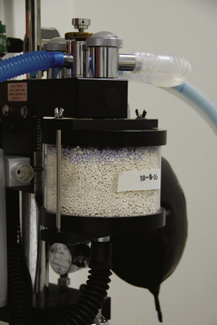
FIGURE 4-37 The color change to violet indicates exhaustion of the carbon dioxide absorbent and a need to change the granules. Note that some granules turn from pink to white.
• When a capnograph is used to monitor the patient, the concentration of carbon dioxide during peak inspiration should be at or near 0 mm Hg if the absorbent is working correctly. A higher carbon dioxide level at peak inspiration indicates possible exhaustion of the absorbent (although there are other causes of elevated inspired CO2 such as a nonfunctional expiratory unidirectional valve).
Granules should be discarded when no more than one third to one half have changed color; and regardless of whether or not any of the previously mentioned indicators are evident, the granules should always be changed after 6 to 8 hours of use.
Safety
Recent studies have shown that some absorbents containing relatively high concentrations of strong bases such as KOH may react with sevoflurane to produce a potentially nephrotoxic substance known as compound A. The production of this substance has been found to have no clinically significant adverse effects in veterinary patients, however.
After use, absorbents may also become desiccated (dried out) and produce a variety of adverse effects. When desiccated, absorbent containing KOH and barium hydroxide (an ingredient found in an older absorbent known as barium hydroxide lime) can react with some anesthetics (particularly sevoflurane) to produce excessive heat and carbon monoxide, formaldehyde, and other various toxins that are harmful to the patient. These effects are minimized, however, by using absorbents without barium or potassium hydroxide and with lower concentrations of sodium hydroxide. For this reason, absorbents containing barium hydroxide have recently been discontinued in the United States, and newer agents containing no KOH and lower amounts of NaOH or no NaOH are available (such as KOH-free sodium hydroxide lime or calcium hydroxide lime). In any case, when purchasing an absorbent, be sure that it is compatible with the anesthetic you are using.
Pressure Manometer
The pressure manometer (not to be confused with the tank pressure gauge or line pressure gauge) (see Figure 4-33, D) indicates the pressure of the gases within the breathing circuit and by extension the pressure in the animal’s airways and lungs. This pressure is most often expressed in centimeters of water (cm H2O), although on some machines the pressure may be expressed in millimeters of mercury (mm Hg) or kilopascals.
Use: The pressure manometer is used when bagging an animal to determine the pressure being exerted on the animal’s lungs when the anesthetist squeezes the reservoir bag (Figure 4-38). The pressure manometer should read 0 to 2 cm of water when the patient is breathing spontaneously. It should read no more than 20 cm of water (15 mm Hg) in small animals, or 40 cm of water (30 mm Hg) in large animals, when positive-pressure assisted or controlled ventilation is provided, unless the chest cavity is open, in which case the pressure can be somewhat higher. Excessive pressure in the circuit can result in dyspnea, lung damage, or pneumothorax. Therefore the pressure must be watched closely during any anesthetic procedure.
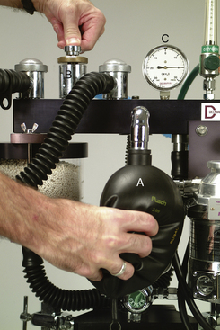
FIGURE 4-38 Providing manual ventilation or “bagging” the patient. The pop-off valve (B) is closed, and the bag (A) is squeezed while the pressure manometer (C) is watched to ensure that safe pressure is not exceeded. The pop-off valve is immediately opened as soon as pressure on the bag is released.
Higher pressure may be needed in an animal with pulmonary dysfunction, such as a dog with gastric dilatation–volvulus or a colicky, bloated horse. In the case of the dog with gastric dilatation–volvulus, pressures of 30 to 35 cm may be needed to deliver a reasonable tidal breath, and in bloated horses pressures up to 50 to 55 cm may be necessary.
Air Intake Valve (Negative Pressure Relief Valve)
An air intake valve is present on some machines either as a separate part or incorporated into the inspiratory unidirectional valve or the pop-off valve. This valve admits room air to the circuit in the event that negative pressure (a partial vacuum) is detected in the breathing circuit, a situation indicated by a collapsed reservoir bag. If a partial vacuum develops, the patient will be unable to fill its lungs and will develop hypoxemia because of inadequate oxygen levels. This may happen when the machine is incorrectly assembled or when an active scavenging system is exerting excessive suction.
Negative pressure may also develop in the circuit if the oxygen flow rate is too low or if the tank runs out of oxygen. The air intake valve ensures that the patient always receives some oxygen by admitting room air (which contains 21% oxygen) into the circuit. Even though this situation is not ideal, it is preferable that the patient breathe room air rather than none at all, as would be the case if the air intake valve were not present.
Breathing Tubes and Y-piece
The inspiratory and expiratory breathing tubes (corrugated breathing tubes) complete the breathing circuit by carrying the anesthetic gases to and from the patient. Each tube is connected to a unidirectional valve at one end and to the Y-piece at the other end. They are made of rubber or plastic and come in three sizes: (1) large animal (50-mm diameter); (2) small animal (22-mm diameter); and (3) small animal pediatric (15-mm diameter) (Figure 4-39, A and B). An alternative configuration known as a Universal F-circuit is a type of breathing tube in which the inspiratory tube is located within the expiratory tube. This arrangement is designed to conserve body heat. As the cold inspired gases travel though the inner turquoise tube, the warm expired gases travel through the outer, transparent tube, warming the inspired gases (Figure 4-39, C).
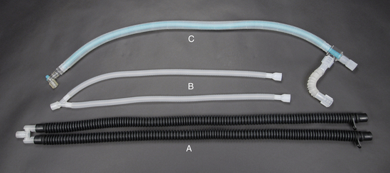
Use
Before using the machine, select the appropriate breathing tubes for the patient. Standard small animal tubes are used on small animal machines for patients over 7 kg body weight, whereas pediatric tubes are recommended for patients weighing 2.5 to 7 kg, to reduce mechanical dead space. Large animal tubes are designed for use only on large animal machines. One end of each tube must be firmly attached to the inspiratory and expiratory unidirectional valves, and the other end of each tube to the Y-piece, which connects the two tubes together. The remaining port of the Y-piece is then connected to a mask or to an ET tube.
NON-REBREATHING SYSTEMS
Although the rebreathing systems just discussed are well suited to many patients, very small patients (those under 2.5 to 3 kg body weight) require the use of an alternative machine configuration called a non-rebreathing (semiopen) system. In a non-rebreathing system, little or no exhaled gases are returned to the patient but are instead evacuated by a scavenger connected to a pop-off or overflow valve, or to an exit port. If no gases are returned to the patient, the system is described as open; if some gases return, the system is described as semiopen. The characteristics of rebreathing and non-rebreathing systems are compared in Table 4-2.
TABLE 4-2
Comparison of Rebreathing and Non-Rebreathing Systems
| Parameters | Non-Rebreathing (Open or Semiopen) | Rebreathing (Semiclosed or Closed System) |
| CO2 absorption | Not required | Must have CO2 absorber canister |
| Changes in depth of anesthesia | Fast | Slow |
| Oxygen flow rates | High flow rates: generally must equal or exceed the respiratory minute volume | Low-flow rates: considerably less than the respiratory minute volume |
| Cost of operation | High because of the amount of oxygen and anesthetic used | Low, because less oxygen and anesthetic used |
| Amount of waste gas produced | High | Low |
| Pop-off valve position | Full open, or no pop-off | Closed (total rebreathing) or partly open (semiclosed rebreathing) |
| Heat and moisture conservation (from exhaled gases) | Poor | Good |
| Vaporizer position | Outside of the breathing circuit (no circle present) | VOC or VIC |
| Size of animal | Any size: limited only by the total gas flow that is delivered; generally recommended for animals under 7 kg | Only for animals over 7 kg (if pediatric hoses used, can be used for animals 2.5-7 kg also) |
When a non-rebreathing system is used, the rebreathing circuit is disabled by detaching the fresh gas hose connector from the vaporizer outlet port or the common gas outlet if present. Then a non-rebreathing circuit is attached in its place. As with a rebreathing system, the non-rebreathing system can best be understood by tracing the path of the oxygen from the compressed gas cylinder to the patient and ultimately to the scavenging system.
Just as in a rebreathing system, oxygen (and nitrous oxide gas, if used) flows from the tank, through a flow meter, and into the vaporizer. After exiting the vaporizer, however, the gases follow a different path. Instead of routing the fresh gas into the circle as occurs with a rebreathing system, the fresh gas is routed directly to the patient. Exhaled gases pass through another hose, then in most systems enter a reservoir bag, and ultimately are released into the scavenging system through an overflow valve or other exit port. In this system a carbon dioxide absorbent is not needed, because exhaled gases are vented from the system immediately after exhalation.
Non-Rebreathing Circuits
Because of the fundamental difference in its structure, several components that are used in a rebreathing circuit are not present in a non-rebreathing circuit. These include the carbon dioxide absorber canister, pressure manometer, and unidirectional valves.
Non-rebreathing circuits are available in several configurations with a confusing variety of names, including (1) Bain coaxial circuit, (2) Ayres T-piece, (3) Magill circuit, (4) Lack circuit, (5) Jackson-Rees circuit, and (6) Norman mask elbow. These circuits are lightweight, are easy to move and position, and are comparatively inexpensive.
Common parts of each of these circuits include an ET tube connector, a fresh gas inlet, a reservoir bag, an overflow valve or exit port, and an associated scavenger tube to connect the overflow valve or exit port to the scavenging system. Most also have a corrugated breathing tube joining the ET tube connector and reservoir bag. The overflow valve may function like an expiratory unidirectional valve or may be opened and closed in a similar manner as the pop-off valve of a rebreathing system. Where these circuits differ is in the position of the fresh gas inlet, reservoir bag, and overflow valve or exit port. Non-rebreathing circuits are grouped using the Mapleson classification system, into classes A though F based on the position of these parts (Figure 4-40). Note that only class A, modified A, modified D, E, and F are in common use in veterinary patients.

FIGURE 4-40 A, Mapleson A System (Magill). B, Modified Mapleson A System (Lack). C, Mapleson D System. D, Modified Mapleson D System (Bain coaxial). E, Mapleson E System (Ayre’s T-piece). F, Mapleson F System (Jackson-Rees). G, Mapleson F System (Norman mask elbow).
Magill Circuit (Mapleson A System)
The Magill circuit (see Figure 4-40, A) has an overflow valve at the patient end of the breathing tube. Both the fresh gas inlet and the reservoir bag are located away from the patient at the opposite end of the breathing tube. Fresh gas flow pushes exhaled gases through the overflow valve. The chief advantage of this system is the relatively low fresh gas flow required during spontaneous ventilation (0.7 to 1.0 × the RMV). It is therefore feasible to use this system for medium or large patients. When a patient is manually ventilated, some rebreathing of expired gases may occur with this system, and for that reason it is not recommended for providing controlled ventilation.
Lack Circuit (Modified Mapleson A System)
The Lack circuit (see Figure 4-40, B) is similar to the Magill circuit, except that it has an expiratory tube that runs from the ET tube connector to an overflow valve near the bag. In this system the fresh gas inlet, the overflow valve, and the reservoir bag are located away from the patient at the opposite end of the breathing tube. This system is used in a similar way as the Magill circuit.
Bain Coaxial Circuit (Modified Mapleson D System)
The Mapleson D system (see Figure 4-40, C) has a fresh gas inlet at the patient end of the breathing tube. Both the overflow valve and the reservoir bag are located away from the patient at the opposite end of the breathing tube. The overflow valve may be built into the bag or near the bag. The Bain coaxial circuit (see Figure 4-40, D) is a modification of the Mapleson D system in which the tube supplying fresh gas is surrounded by the larger, corrugated tubing (which conducts gas away from the patient). This “tube within a tube” arrangement allows the incoming gases to be warmed slightly by the exhaled gases that surround them, before reaching the patient. This beneficial effect is minimal, however, when high fresh gas flow rates are used.
When this system is used, some rebreathing of waste gases will occur unless an oxygen flow rate of two to three times the RMV is used (up to a maximum of 3 L/min for patients under 7 kg), but when the patient is breathing spontaneously, minimal rebreathing occurs at a flow rate of 0.5 to 1 × the RMV.
Ayre’s T-piece (Mapleson E System)
The Ayre’s T-piece (see Figure 4-40, E) is a T-shaped tube with a fresh gas inlet entering the patient end of the breathing tube at a 90-degree angle (like the base of the letter T). Unlike other circuits, the Ayre’s T-piece does not have a reservoir bag at the opposite end of the breathing tube. The fresh gas flow with this system should be two to three times the RMV.
Jackson-Rees Circuit and Norman Mask Elbow (Mapleson F Systems)
The Jackson-Rees circuit and the Norman mask elbow (see Figure 4-40, F and G) have a fresh gas inlet at the patient end of the breathing tube and a reservoir bag at the opposite end. The fresh gas inlet of a Jackson-Rees circuit enters the breathing tube at a 45- to 90-degree angle. The Norman mask elbow is almost identical to a Jackson-Rees circuit, except that the ET tube connector is at right angles to the breathing tube. This circuit may slightly reduce mechanical dead space as compared with an Ayre’s T-piece or Jackson-Rees, but otherwise is used in a similar manner as these circuits. The fresh gas flow with both the Norman mask elbow and the Jackson-Rees should be two to three times the RMV.
OPERATION OF THE ANESTHETIC MACHINE
At the beginning of each day, before using an anesthetic machine, the anesthetist must assemble the machine or machines to be used, check the oxygen and liquid anesthetic levels, check the low pressure system for leaks (see Procedure 13-1), and set the pop-off or overflow valve (Procedure 4-1, p. 135). Before each case the anesthetist must also choose between a small animal and a large animal machine, determine what type of breathing circuit to use (rebreathing or non-rebreathing), and choose carrier gas flow rates. (Procedure 4-2, p. 135 is a checklist to be followed when setting up anesthetic equipment.)
TECHNICIAN NOTE
The appropriate choice of a machine (large animal versus small animal), reservoir bag, breathing tubes, oxygen flow rates, and breathing circuit type is based on patient body weight.
Choosing a Machine
The decision of whether to use a small animal or large animal machine is based on patient weight. A small animal machine is intended for patients under 150 kg (about 350 lb), and a large animal machine is intended for patients weighing 150 kg or more.
Machine Assembly
Before assembling the machine, choose the breathing circuit, and, if using a rebreathing circuit, choose appropriately sized breathing tubes and rebreathing bag. These decisions are based on patient weight. Once the equipment has been chosen, connect all necessary parts including the vaporizer inlet and outlet port hoses, the breathing circuit if using a non-rebreathing system, and the rebreathing bag and breathing tubes if using a rebreathing system. Finally, connect the scavenging system hoses and any other parts required for the machine you are using, such as the common gas outlet.
Checking Oxygen and Anesthetic Levels
The oxygen supply must be checked to be sure enough oxygen remains to complete the procedure. Guidelines regarding oxygen supply may be found in the discussion of the tank pressure gauge on p. 107.
Anesthetic vaporizers must also be checked to make sure that enough anesthetic remains in the vaporization chamber. Most vaporizers have an indicator window at their base that allows the technician to inspect the amount of liquid anesthetic remaining. In order for the vaporizer to function properly, the liquid anesthetic must be between the full and empty lines of the window. The vaporizer should be refilled as needed but should be kept at least half full at all times. A keyed filling device should be used for this purpose (see Figure 4-31). Overfilling a vaporizer will result in anesthetic overdose, and underfilling will result in an inability to keep the patient anesthetized. The vaporizer should also be turned off when the machine is not in use.
Choice of Rebreathing Versus Non-Rebreathing System
The decision of whether to use a rebreathing system or a non-rebreathing system is generally made on the basis of patient size. This is because the patient’s respiratory drive—the force generated by the respiratory muscles during breathing—is directly related to body weight. The respiratory drive in very small patients is insufficient to move gas through areas of resistance to air movement (primarily the unidirectional valves, carbon dioxide canister, and breathing tubes).∗ In contrast, non-rebreathing systems offer little resistance to air movement, a significant advantage for these patients. The choice of system to be used is important in terms of machine setup and use because it will determine the following:
• The type of equipment required (a conventional anesthetic machine with or without a non-rebreathing system such as a Bain coaxial circuit)
• Position of the pop-off valve (closed, partially open, or open)
• Carrier gas flow rates (oxygen and nitrous oxide, if used)
Rebreathing systems may be safely used on all larger patients but, as mentioned, are not safe for very small patients. For this reason, most anesthetists recommend a rebreathing system for patients weighing 7 kg (15 lb) or over, unless the system is fitted with pediatric hoses (and assuming the unidirectional valves are of a lightweight and nonstick design), in which case it may also be used on patients as small as 2.5 to 3 kg. Patients smaller than 2.5 to 3 kg should be placed on a non-rebreathing system.
Although patient weight is the primary determining factor in making a decision concerning which system to use, other advantages and disadvantages of each of these systems must be considered, including the following:
• Cost: Closed rebreathing (total) systems are most economical because the very low gas flow rates used with these systems conserve carrier and anesthetic gases. Semiclosed rebreathing (partial) systems use higher gas flow rates and so are not as economical as closed rebreathing systems. Non-rebreathing systems are the least economical because they use the highest gas flow of all the systems and consequently use more carrier and anesthetic gas per unit body weight.
• Control of anesthetic depth: The speed at which the anesthetist can change anesthetic depth depends in part on the type of system used. Changes take longer with a rebreathing system because the flow of fresh oxygen and anesthetic into the system is low compared with the volume of the circuit (Box 4-2). Therefore when the vaporizer setting is changed, it will take longer for the anesthetic concentration in the breathing circuit to reach the desired level. A non-rebreathing system allows a much faster turnover of gases because flow rates of fresh gas are higher relative to the volume of the circuit. Because of this higher flow and because the fresh gas is often delivered very close to the patient, changes in the anesthetic concentration breathed in by the patient occur more rapidly. This means that the anesthetic concentration breathed by the patient is very close to that indicated by the dial with a non-rebreathing system. In contrast, with a rebreathing system, the concentration of anesthetic breathed in by the patient will not be the same as that indicated on the dial for several to many minutes after the setting has been changed.∗
• Conservation of heat and moisture: Fresh gas entering a breathing system from the vaporizer is relatively cool and dry, compared with the patient’s exhaled gases, which are warm and moist. Inspired fresh anesthetic gases have a relative humidity close to 0% and a temperature of approximately 16° C (61° F), whereas exhaled gases have a relative humidity of almost 100% and a temperature close to 25° C (77° F). Rebreathing systems automatically warm and humidify fresh gas that enters the circuit as it mixes with the patient’s expired gases. In non-rebreathing systems, the warmed and humidified gases exhaled by the patient exit through the scavenger, and the patient breathes only the cool, dry fresh gas. Non-rebreathing systems are therefore associated with significant heat and water loss from the patient. In addition, the dry anesthetic gases may impair tracheobronchial ciliary function and dry the airways.
• Production of waste gas: Closed rebreathing systems release little waste anesthetic gas because oxygen flow rates are low and exhaled gases are recirculated rather than vented through the pop-off valve. Semiclosed rebreathing systems vent some waste anesthetic gas, which varies depending on the carrier gas flow rates used. In contrast, non-rebreathing systems vent nearly all exhaled gas.
Checking the Low-Pressure System for Leaks
The low-pressure system includes the breathing circuit, the vaporizer, and all the tubing between the flow meters and the fresh gas inlet. Checking this system for leaks helps to ensure that the machine is properly assembled and has no damaged or missing parts (Case Study 4-1 illustrates the importance of leak testing any anesthetic machine before use.). The procedure for performing a low-pressure system leak test can be found in Procedure 13-1.
Adjusting the Pop-off Valve
With a semiclosed rebreathing system, the pop-off valve should be adjusted immediately after the leak test is performed. The action ensures that the pop-off valve has not been inadvertently left closed and is set at the right level for the patient. The procedure for adjusting the pop-off valve can be found in Procedure 4-1, p. 135.
Choosing Carrier Gas Flow Rates
At various times during any anesthetic procedure, the anesthetist must determine the appropriate carrier gas flow. Usually oxygen is used alone, but if both oxygen and nitrous oxide are used, flow rate determinations must take into consideration the total flow of both gases as well as the individual flow rates of each gas. (More information on the use of nitrous oxide can be found in Appendix B.)
The flow rates for each anesthetic procedure are calculated using the patient body weight and the VT or RMV. The VT is considered to be approximately 10 mL/kg/min in most anesthesized animals. The RMV is VT multiplied by the respiratory rate in breaths per minute (an average of 20 breaths/min in most patients). Therefore the RMV is considered to be about 200 mL/kg/min.
Flow rates also depend on the type of breathing system (closed rebreathing, semiclosed rebreathing, or non-rebreathing) and the period of anesthesia (i.e., induction, maintenance, or recovery or when changing the anesthetic depth). Relatively high rates are used for non-rebreathing systems at all times regardless of the period of anesthesia. With closed rebreathing systems, flow rates are very low (only enough to meet the metabolic needs of the patient). With semiclosed rebreathing systems, flow rates vary from relatively low rates when maintaining a patient at a desired anesthetic depth to relatively high rates during induction and recovery and when changing anesthetic depth. This is because higher flows cause the anesthetic concentration within the breathing circuit to
change more rapidly and consequently cause the patient’s anesthetic depth to change more quickly. This is desirable when a rapid change in anesthetic depth is necessary, such as during induction and when the patient’s anesthetic level is excessive. See Box 4-4 for recommended flow rates, Box 4-5 for examples of flow rate calculations, and Tables 4-3 and 4-4 for quick look-up charts for rebreathing and non-rebreathing systems respectively. TECHNICIAN NOTE
With semiclosed rebreathing systems, flow rates vary from relatively low when maintaining a patient at a desired anesthetic depth to relatively high during induction and recovery and when changing anesthetic depth. This is because higher flows cause the patient’s anesthetic depth to change more quickly.
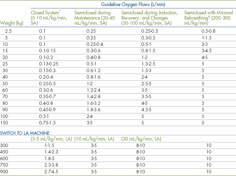
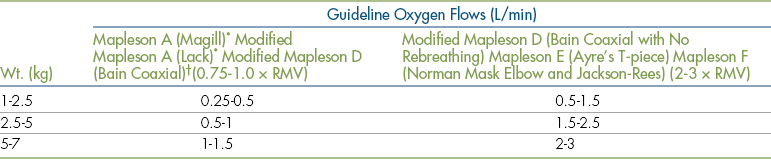
Flow Rates during Mask or Chamber Induction
During mask and chamber induction, very high flow rates are required. Use of high flow rates in the induction period saturates the anesthetic circuit with carrier gas and anesthetic vapor, and dilutes the expired gases of the patient. Otherwise, expired nitrogen gas (N2), which comprises almost 80% of the air in patient’s lungs and bloodstream at the start of the anesthetic period, will enter the circuit and dilute out the anesthetic vapor and oxygen. If high flow rates are used, the nitrogen will be flushed out of the breathing circuit by fresh gas within a few minutes. The flow rate can be decreased to a maintenance level once the patient reaches the desired plane of anesthesia.
For mask induction it is generally agreed that the flow rate per minute should equal 30 times the VT (approximately 300 mL/kg/min) for cats and small dogs, and somewhat less for larger dogs. This works out to a recommended total flow rate of 1 to 3 L/min for animals less than or equal to 10 kg, and 3 to 5 L/min for animals over 10 kg. A flow rate of 5 L/min is recommended for chamber induction regardless of patient body weight.
In large animal anesthesia, mask induction is rarely used, with the exception of neonates, in which case rates similar to those in cats and dogs can be used, and pigs, because of the difficulty in gaining venous access in conscious swine. Small to medium pigs (less than 50 kg) require oxygen flow rates of 3 to 5 L/min during mask induction. A flow rate of 5 L/min is rarely exceeded when larger pigs are masked in order to decrease pollution of the induction area with anesthetic gases, as masks for this size of pig are custom made and may leak. Induction will, however, be much slower, so if faster induction time is required, then flow rates of up to 10 L/min can be used.
Flow Rates When Using a Semiclosed Rebreathing System
After Induction with an Injectable Agent: For animals induced with an injectable anesthetic and subsequently intubated and connected to an anesthetic machine, the flow rate should be relatively high (50 to 100 mL/kg/min). This results in a flow rate of about 500 mL to 5 L/min for small animals, or for large animal patients connected to a small animal anesthetic machine, depending on the patient body weight. Initial flow rates for large animal patients on a large animal machine range from 8 to 10 L/min.
Flow Rates When Making Changes in Anesthetic Depth: It is also desirable to use a higher oxygen flow rate (50 to 100 mL/kg/min) when the patient’s level of anesthesia is too deep or too light and a change in anesthetic depth is desired. Although not absolutely required, use of flows at the higher end of this range will result in more rapid changes in the desired anesthetic concentration within the breathing circuit, and ultimately in the patient’s anesthetic depth.
Flow Rates during Maintenance: Once the animal achieves a satisfactory level of anesthetic depth, the flow rate may be safely reduced to a maintenance level. Rebreathing systems require relatively low flow rates compared with non-rebreathing systems during this period because carbon dioxide is removed from the expired gases, which are then returned to the patient. Provided the carbon dioxide absorbent is effective and there are no leaks in the system, the carrier gas and anesthetic can be recycled continuously, and only a small amount of fresh gas is required. During this period flow rates of 20 to 40 mL/kg/min are recommended for small animals (SA) and 3 to 5 L/min for adult large animals (LA).
Flow Rates during Anesthetic Recovery: When the vaporizer is turned off, the patient enters the recovery period. During this time, even though the vaporizer is turned off, anesthetic gas is exhaled by the recovering patient and remains in the circuit until replaced by fresh oxygen. Recovery will be delayed if this waste anesthetic gas is allowed to remain in the circuit. So it is to the patient’s advantage to remove this waste gas as quickly as possible by taking the following actions.
Immediately after the vaporizer is turned off, increase the flow to the same rate used during induction (50 to 100 mL/kg/min). Then, with the pop-off valve open, use gentle pressure to evacuate the reservoir bag and refill it using short bursts from the oxygen flush valve. These actions will flush out waste anesthetic gas, increase the oxygen concentration in the breathing circuit, and hasten patient recovery. Maintain this higher flow for 5 minutes or until the patient must be extubated.
This same procedure can be followed for patients connected to a large animal anesthetic machine, using flow rates of up to 10 L/min to “flush” the system.
Flow Rates When Minimal Rebreathing of Anesthetic Gases Is Desired: Note that when the oxygen flow rate matches or exceeds the patient’s RMV (at least 200 to 300 mL/kg/min), a rebreathing system can be made to function in a manner similar to a non-rebreathing system. In emergency situations, such as exhaustion of the carbon dioxide absorbent, these rates help to flush exhaled gases from the breathing circuit through the pop-off valve and may be necessary until the problem is rectified.
Flow Rates When Using a Closed Rebreathing System
Closed rebreathing systems are normally used only during anesthetic maintenance. When these systems are used, the oxygen flow must equal only the oxygen requirements of the animal. The minimum metabolic oxygen requirement for the anesthetized animal is 5 to 10 mL/kg/min. (See Appendix D). The anesthetist should be aware that when flow rates of less than 250 mL/min are used, some precision vaporizers and flow meters might not accurately deliver the dialed vaporizer concentration and oxygen flow. Large animal patients, particularly adult horses and cattle, have lower metabolic oxygen requirements, and it is possible that oxygen flow rates as low as 3 to 5 mL/kg/min may be used during maintenance with a closed rebreathing system.
Safety Concerns with a Closed Rebreathing System: Although closed rebreathing systems are more economical than semiclosed rebreathing systems, there are serious safety concerns that must be addressed when a closed rebreathing system is used:
• Carbon dioxide accumulation. If the carbon dioxide absorber in a closed system is not operating efficiently, exhaled carbon dioxide will build up within the circuit. This is less likely to happen in a semiclosed rebreathing system, in which some CO2 is vented to the scavenger.
• Increased pressure in the anesthetic circuit. In a closed rebreathing system, the volume of gas in the system may increase as fresh gas enters the circuit, particularly if the fresh gas flow exceeds the patient’s uptake of oxygen and anesthetic and the pop-off valve is closed. As a result, excessive pressure may build up in the circuit, making it difficult for the animal to exhale. This risk is lessened with a semiclosed rebreathing system because the pop-off valve is partially to fully open and excessive gas is vented.
• These disadvantages must be balanced against the economic advantages of a closed rebreathing system and the fact that little or no waste anesthetic gas is produced when flow rates are low. In most situations (e.g., where continuous monitoring of the patient and the anesthetic machine is not possible) the anesthetist may prefer to use a semiclosed rather than a closed rebreathing system for the safety reasons just outlined. The anesthetist may choose to err on the side of wasting some gas by using higher gas flow rates rather than risk accumulation of carbon dioxide and depletion of oxygen within the circuit. A closed rebreathing system can easily be converted to a semiclosed rebreathing system by opening the pop-off valve (except when bagging the patient) and increasing the oxygen flow rate.
Procedures used in the operation of a closed rebreathing system are listed in Appendix D.
Flow Rates When Using a Non-Rebreathing System
Non-rebreathing systems require relatively high flow rates per unit body weight during all periods of general anesthesia (induction, maintenance, and recovery) because the removal of carbon dioxide from the circuit is dependent on fresh gas flow, which must be sufficient to ensure that there is minimal rebreathing of exhaled gases. Therefore close attention must be given to the selection of an appropriate flow rate. Recommended rates are based on body weight and the Mapleson classification of the circuit. Because these systems are generally used for patients weighing less than 7 kg, maximum rates listed are based on this body weight.
With Mapleson A systems (Magill circuit), Modified Mapleson A systems (Lack circuit), and modified Mapleson D systems (Bain coaxial circuit), carrier gas flow should be near the RMV (200 mL/kg/min). This equals about 0.5 to 1.5 L/min depending on patient size.
Modified Mapleson D systems (Bain coaxial circuit) with no rebreathing, Mapleson E systems (Ayre’s T-piece), and Mapleson F systems (Jackson-Rees circuit or Norman Mask Elbow circuit) require an oxygen flow rate of two to three times the RMV (400 to 600 mL/kg/min) with a maximum flow of 3 L/min for patients under 7 kg. This equals about 1 to 3 L/min depending on patient size.
These recommended flow rates are high enough to prevent most exhaled gases from being rebreathed by the patient. Some rebreathing of gas can occur, however, particularly during peak inspiration, if the respiratory rate is rapid, or if the volume of the circuit is lower than it should be for the size of the patient. The anesthetist can partially control the amount of gas rebreathed by adjusting the oxygen flow rate. For example, when using a Bain coaxial circuit, if the anesthetist selects a high oxygen flow rate (e.g., 2 L/min for a 4-kg cat), there is little return of exhaled gases to the patient. The system is therefore truly non-rebreathing. At lower flow rates (e.g., 500 mL of oxygen per minute for the same 4-kg cat), significant rebreathing of exhaled gases may occur. So even though these systems are technically classified as non-rebreathing, the way they function is somewhat dependent on carrier gas flow.
Summary
Within the aforementioned guidelines, there is considerable leeway for the anesthetist’s own judgment in determining the flow rate for any particular procedure. (See Boxes 4-4 and 4-5 for a summary of currently recommended flow rates and examples of flow rate calculations.) In many cases the ultimate decision is based on both economic factors and the needs of the patient. For instance, low gas flow rates are more economical than high flow rates because less carrier gas and anesthetic are used, but higher rates may be necessary at certain times (such as induction, recovery, and change in anesthetic levels) or during management of a crisis. On the other hand, if the patient is small, the cost of anesthetic gases is less significant.
CARE AND MAINTENANCE OF ANESTHETIC EQUIPMENT
As with any piece of equipment, the anesthetic machine requires periodic maintenance to ensure proper performance. In addition to routine maintenance procedures performed by hospital staff, a qualified repair professional should be contracted to examine and test all parts of each anesthetic machine on an annual basis.
TECHNICIAN NOTE
In addition to routine maintenance procedures performed by hospital staff, a qualified repair professional should be contracted to examine and test all parts of each anesthetic machine on an annual basis.
Compressed Gas Cylinders
Usually, compressed gas cylinders are regularly inspected and maintained by the company that fills them, and they require no regular maintenance by hospital staff. At times, however, tank valve stems become difficult to turn. If excessive force is needed, the tank should not be used again until it is sent in for inspection and maintenance. Petroleum products (e.g., grease and kerosene) should not be used to lubricate oxygen tanks or their connections because an explosion could occur when these materials contact oxygen released from the tank. Silicon or Teflon-based lubricants are generally safe for this use. When empty, compressed gas cylinders must be removed, refilled, and replaced as described in the following paragraphs.
Removing and Replacing E Tanks: When viewed from the front face, the E-tank valve has three holes—one outlet port, through which the gas exits the cylinder, and two receiving holes for the pin-index safety system. The outlet port fits on the nipple of the yoke with a single washer placed in between to prevent leakage. The pin-index holes fit onto the pins of the yoke (see Figure 4-18). To remove an E tank from the machine, be sure the tank valve is closed and the oxygen is purged from the system. Place your shoe under the tank to support it. Loosen the wing nut, and back the valve port off of the yoke. Carefully remove your shoe and lower the tank until the valve clears the yoke. The tank should be stored in an upright position, on a cart or chained to the wall, until it is picked up by the company for refilling.
When replacing a tank on a machine, first inspect the valve port for cleanliness, then place a single washer between the valve port and the nipple. There are two types of washers. Flanged washers have a flange on one side that fits inside the outlet port. A flat washer, which has no flange, fits on the nipple of the yoke (see Figure 4-18). Either type may be used as long as it is clean, undamaged, and smooth with no surface defects. After either a flanged or flat washer has been placed, gently raise the tank into place, lining up the valve port and the pin holes with the corresponding structures on the yoke. Tighten the wing nut as securely as you are able to by hand. Open the tank slowly and listen for leaks. If the tank leaks, recheck the holes for proper alignment, tighten the wing nut further, or use a new washer. One of these maneuvers should resolve the problem.
Detaching and Reattaching H Tanks: Most remote oxygen sources have a bank of two or more H tanks next to one another (see Figure 4-15). One or more of the tanks is attached to a pressure-reducing valve and a series of lines that pipe the gas to DISS connectors throughout the hospital (see Figure 4-16). First, be sure that no patients are currently receiving oxygen. Then turn the tank off before attempting to remove the valve. Remove the pressure-reducing valve by using a hex wrench to loosen the nut connecting the valve and outlet port, and then remove the valve by hand. Immediately attach the pressure-reducing valve to another full H tank.
Tank and Line Pressure Gauges, Pressure Manometer, and the Oxygen Flush Valve
Some parts of the anesthetic machine including the tank pressure gauge, line pressure gauge, pressure manometer, and oxygen flush valve require no regular maintenance. A repair professional should check these parts for proper function during an annual maintenance visit or when a problem is suspected.
Pressure-Reducing Valve
The pressure-reducing valve may need to be adjusted if the line pressure is not correct (40 to 50 psi). Many valves have an external adjusting screw that is turned left or right to increase or decrease the pressure. Consult the owner’s manual for specific directions.
Flow Meters
Although flow meters require no regular maintenance, always treat them gently by not overtightening the valve when turning them off. If excessive hand pressure is necessary to stop oxygen flow, the valve is damaged and needs to be replaced.
Flow meter accuracy can be assessed easily by performing the following test:
• Empty the reservoir bag completely.
• Close the pop-off or overflow valve.
• Occlude the Y-piece or ET tube connector.
• Choose a flow setting that corresponds to the size of the reservoir bag in liters (e.g., 2 L/min for a 2-L bag or 3 L/min for a 3-L bag).
The flow meter is accurate if the bag fills completely in 1 minute.
Vaporizer
Precision vaporizers must be serviced and maintained regularly to ensure accurate output. Because they are the most complex part of the anesthetic machine, they should be cleaned, tested, and recalibrated by the manufacturer or other qualified personnel every year or as indicated by the manufacturer. It may be necessary to remove the vaporizer from the anesthetic machine and send it away for servicing. Many companies provide a “loaner” replacement during the servicing period.
Precision vaporizers designed for halothane or methoxyflurane should be emptied of anesthetic every 6 to 12 months to help remove the buildup of preservative within the vaporizer. Despite periodic emptying, a halothane precision vaporizer may eventually become clogged with preservative and other residue and should be serviced if the anesthetic is discolored, dial movement is sticky, or the patient can no longer be maintained at a satisfactory anesthetic depth even at high vaporizer settings. Isoflurane and sevoflurane are supplied without a preservative, so periodic emptying is not usually necessary.
Vaporizer Inlet Port, Outlet Port, Common Gas Outlet, and Fresh Gas Inlet
The vaporizer inlet port, outlet port, common gas outlet, and fresh gas inlet are all components of the low-pressure system. The hose commonly attached to these parts is subject to damage, so check all hoses for holes or defects and replace them as necessary. A routine low-pressure leak test of the machine will usually uncover any damage.
Unidirectional Valves
Periodically the unidirectional flow valves should be disassembled, cleaned, and inspected to prevent a buildup of water vapor, mucus, and dust from the carbon dioxide absorbent and other material. Valves that are not cleaned may become sticky and adhere to the machine housing, impeding airflow through the circuit or preventing closure.
To clean these valves, unscrew the valve collar and remove the valve parts. Clean the dome, collar, valve, valve seat, and gaskets with alcohol or mild disinfectant like chlorhexidine gluconate. After drying the parts, inspect the valve and valve seat to be sure they are not damaged or warped. An incompetent valve will allow reinhalation of expired carbon dioxide—a serious or potentially fatal complication. Finally, reassemble the valve, being sure that it is properly positioned on the valve seat.
The integrity of the unidirectional valves can be tested as follows:
• Detach the expiratory breathing tube from the Y-piece.
• Place the end of the tube up to your mouth with the surgical mask in between, so that the air will pass through the mask.
• Attempt to inhale through the tube.
• Now detach the inspiratory breathing tube from the Y-piece and place the end up to your mouth as before.
Any air movement through either tube indicates an incompetent valve, which must be serviced before the machine is used again.
Pop-off Valve
Although the pop-off valve does not require regular maintenance, it should be checked for proper operation and adjusted (Procedure 4-1, p. 135) before commencement of any procedure. This should be done at the beginning of every day immediately after the low-pressure system leak test. The valve should also be checked periodically during the anesthetic procedure to maintain optimum gas volume within the circuit.
Reservoir Bag, Breathing Tubes, and Y-Piece
Between each case, the reservoir bag, the breathing tubes, and the Y-piece or the non-rebreathing system should be removed and cleaned to prevent interpatient transfer of infectious agents that collect inside. Wash each part with a mild soapy disinfectant such as chlorhexidine gluconate, then rinse thoroughly. A surgical scrub brush or bottle brush is useful in cleaning equipment surfaces. Hang these parts in a vertical position until completely dry. Before reattaching them, check each part for integrity. The neck of the bag is especially vulnerable, and holes commonly develop in this location.
Carbon Dioxide Absorber Canister
The carbon dioxide absorbent must be changed according to the guidelines indicated on p. 120. To change the absorbent, you must first remove the absorber canister and dispose of the absorbent granules. Next disassemble the canister, clean each part with mild soapy disinfectant, and rinse each part thoroughly. Dry each part, check all gaskets for integrity, and reassemble the canister. Fill the clean canister loosely with fresh granules but leave at least 1 cm or ½” of air space at the top to allow unimpeded airflow. Gently shake the canister to distribute the granules evenly. This helps prevent channels from forming in the granules, which could reduce the efficiency of the absorbent. Following reassembly, the canister must be airtight. An airtight seal may be prevented if any granules inadvertently become lodged in a seal or gasket.
Absorbent granules should not be handled without gloves, and dust from the absorbent granules should not be allowed to enter the tubing or hoses of the machine or be breathed in by the technician, because it is irritating to skin and corrosive to mucous membranes. Also, some machines have a water trap below the absorber canister. Any water that collects in this trap should be periodically drained.
Disinfecting Anesthetic Equipment
Some anesthetic equipment components including ET tubes, laryngoscope blades, and face masks will require more thorough disinfection because this equipment directly contacts the patient’s airway or oral cavity. Otherwise, equipment used on a patient harboring certain viruses or bacteria (e.g., feline upper respiratory viruses, Bordetella, and other respiratory pathogens) may transmit infectious agents to the next patient.
First disassemble any parts that can be removed such as laryngoscope blades and mask gaskets; then wash the parts thoroughly with disinfectant, rinse, dry, and reassemble. Unfortunately, there is no ideal agent for disinfection, but several can be used. Chlorhexidine gluconate is relatively harmless to tissues but is not effective against all microorganisms and spores. Glutaraldehyde solutions (2%) are effective against many microorganisms but are stable for only 2 to 4 weeks and so must be periodically replaced. Ethylene oxide gas is an effective sterilizing agent but requires special equipment for safe use. Both glutaraldehyde and ethylene oxide are potentially toxic and may cause severe tissue injury to hospital personnel and to the patient if the anesthetic equipment or supplies are not properly handled. Personnel who work with these chemicals must have special training in their safe use.
All items exposed to any chemical solution should be thoroughly rinsed with water after cleaning and dried before use. Rubber may absorb some chemicals, which, if not completely removed by rinsing, may cause burns on contact with the patient’s airway or skin. Ethylene oxide is particularly well absorbed by materials being sterilized, and ET tubes exposed to this substance or glutaraldehyde have been known to cause tracheal necrosis.
Autoclaving causes rubber surfaces to become brittle and crack, and prolonged exposure to disinfectants may cause rubber surfaces to deteriorate. Therefore, damaged masks and reservoir bags, as well as ET tubes that are damaged or have leaking or nonfunctional cuffs, should be discarded.
KEY POINTS
1. Endotracheal tube placement offers many advantages and increases patient safety for both injectable and inhalant anesthetic techniques.
2. Proper endotracheal tube selection, preparation, placement, and monitoring are of primary importance in any general anesthetic procedure.
3. Anesthetic machines deliver precise amounts of carrier and anesthetic gases, remove carbon dioxide, and permit manual ventilation of anesthetized patients.
4. An anesthetic machine can be used as a source of oxygen in emergencies.
5. Compressed oxygen cylinders store carrier gases under high pressure. Cylinders come in various sizes and capacities, and the gas contained within is identified by the color of the cylinder.
6. The pressure-reducing valve decreases carrier gas pressure to a safe operating pressure of 40 to 50 psi before the gas enters the flow meters.
7. The flow rate of each carrier gas is set by its respective flow meter. Flows are generally expressed in liters per minute. The flow rate indicates to the anesthetist how much gas is being delivered to the patient at any given time.
8. Liquid anesthetic is vaporized and added to the carrier gas in the vaporizer. The combination of anesthetic vapor, oxygen, and nitrous oxide (if present) is called fresh gas.
9. Vaporizers may be precision or nonprecision, based on their construction. Precision vaporizers are commonly used for anesthetics with high vapor pressures and provide compensation for variations in temperature, gas flow rate, and back pressure.
10. Precision vaporizers are found outside of the anesthetic circuit (VOC), whereas nonprecision vaporizers are found inside the anesthetic circuit (VIC).
11. The reservoir bag (rebreathing bag) serves as a reservoir to receive and provide gas during the respiratory cycle. It can be used to monitor the animal’s ventilation and to deliver oxygen (with or without anesthetic) to the patient by a process called bagging.
12. Inhalation and exhalation unidirectional valves permit only one-way flow of gas through the breathing circuit and prevent rebreathing of CO2.
13. Waste gas exits the machine at the pop-off valve and is removed by the scavenging system.
14. Carbon dioxide is removed from a rebreathing circuit by absorbent granules. These granules must be replaced when saturated, or at least every 6 to 8 hours, to prevent rebreathing of carbon dioxide.
15. The pressure manometer measures the pressure of gases within the breathing circuit and the patient’s lungs.
16. Anesthetic circuits may be classified as rebreathing (either closed or semiclosed) or non-rebreathing. Rebreathing systems use lower oxygen flow rates but must provide for carbon dioxide absorption. Non-rebreathing systems, such as the Bain system, require relatively high flow rates and are commonly used in small patients.
17. Carrier gas flow rates vary with the period of anesthesia and type of anesthetic circuit used (i.e., rebreathing or non-rebreathing). With a rebreathing system, high flow rates are used during induction, recovery, and changing of anesthetic depth, and lower rates are used during maintenance. When a non-rebreathing system is used, high flow rates are used at all times.
18. Anesthetic equipment requires routine cleaning, inspection, and maintenance.
REVIEW QUESTIONS
1. When the oxygen tank is half full, the tank pressure gauge will read approximately:
2. Nitrous oxide is present in the tank as a:
3. The amount of oxygen an animal is receiving is indicated by the:
4. Flow meters that have a ball for reading the gauge should be read from the __________ of the ball.
5. The most commonly recommended ratio for nitrous oxide and oxygen flow rates is:
a. 50% oxygen and 50% nitrous oxide
b. 80% oxygen and 20% nitrous oxide
c. 23% oxygen and 77% nitrous oxide
6. The minimum size for the reservoir bag can be calculated as:
7. The flutter valves on an anesthetic machine help:
8. The pop-off valve is part of the anesthetic machine and helps:
a. Vaporize the liquid anesthetic
b. Prevent excess gas pressure from building up within the breathing circuit
9. In small animal anesthesia, when the patient is bagged, the pressure manometer reading should not exceed:
10. Rebreathing systems, when used with standard small animal corrugated breathing tubes, are best reserved for animals weighing more than 7 kg.
11. Rebreathing is determined primarily by the:
12. Non-rebreathing systems should have maintenance flow rates that are:
13. The negative pressure relief valve is particularly important when:
a. Nitrous oxide is being used
b. There is no scavenging system
14. The tidal volume of an anesthesized animal is considered to be _________ mL/kg of body weight.
For the following questions, more than one answer may be correct.
16. A reservoir bag that is not moving well may indicate that:
a. The endotracheal tube is not in the trachea
b. The animal has a decreased tidal volume
17. The anesthetist will know when the granules in the carbon dioxide absorber have been depleted because the:
18. An increase in the depth of anesthesia can be achieved quickly by:
a. Having high oxygen flow rates
b. Having high vaporizer settings
19. The concentration of anesthetic delivered from a nonprecision vaporizer may depend on the:
20. When an anesthetic machine is operating correctly, the pressures in the machine are always: