The Third Stage of Comprehensive Treatment
Finishing
By the end of the second stage of treatment, the teeth should be well aligned, extraction spaces should be closed, tooth roots should be reasonably parallel, and the teeth in the buccal segments should be in a normal Class I relationship. In the Begg technique, major root movements of both anterior and posterior teeth still remained to be done in Stage 3 to obtain root paralleling at extraction sites and proper torque and axial inclination of tipped incisors, and this was accomplished with auxiliary springs. In the modern modified Begg technique, using Tip-Edge brackets, auxiliary springs are augmented with rectangular archwires in Stage 3 (Figure 16-1).
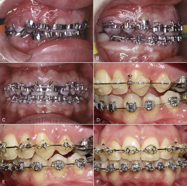
FIGURE 16-1 Stage 3, finishing, in a patient treated in the 1970s with classic Begg technique. A, The Begg appliance in a patient who has had premolar extraction and space closure and is ready for the finishing stage of treatment. Note the ribbon arch bracket turned upside down from the way Edward Angle positioned it. Archwires are pinned into place. B, Uprighting springs and a torquing arch in place. The uprighting springs (used here on lateral incisors, canines, and second premolars) fit into the vertical tube portion of the bracket and are hooked underneath the base archwire to create root-positioning moments. An auxiliary torquing arch is threaded over the archwire and places a lingual force against the tooth above the bracket slot. C, Anterior view of the torquing arch and uprighting springs. D, The finishing stage of treatment with Tip-Edge, a modern extension of the Begg appliance, after tipping the teeth to close space and retract protruding incisors in this Class II patient who had upper premolar extractions. E, Auxiliary uprighting springs (seen here on the maxillary lateral incisor, canine, and second premolar) are used for root positioning, with a different type of spring for the incisors where torque is desired, and a rectangular archwire serves as a template and prevents overcorrection. Note the improvement in both inclination of incisors and root paralleling at the extraction sites. F, Frontal view. Note that the auxiliary spring for torque to incisors now is quite different from the Begg torquing arch or its equivalent for use as an edgewise auxiliary (see Figure 16-6).
With contemporary edgewise techniques, much less treatment remains to be accomplished at the finishing stage, but minor versions of these same root movements are likely to be required. In addition, most cases require some adjustment of individual tooth positions to get marginal ridges level, obtain precise in–out positions of teeth within the arches, and generally overcome any discrepancies produced by errors in either bracket placement or appliance prescription. In some cases, it is necessary to alter the vertical relationship of incisors as a finishing procedure, either correcting moderately excessive overbite or closing a mild anterior open bite.
Although many variations are inevitable to meet the demands of specific cases, it is possible to outline a logical sequence of archwires for continuous arch edgewise technique, and this has been attempted in Box 16-1. The sequence is based on two concepts: (1) that the most efficient archwires should be used, so as to minimize clinical adjustments and chair time, and (2) that it is necessary to fill (or nearly fill) the bracket slot in the finishing stage with appropriately flexible wires to take full advantage of the modern appliance. Appropriate use of the recommended finishing archwires and variations to deal with specific situations in finishing are reviewed in some detail below. Similar recommendations and variations in the first two stages of treatment have been provided in the two previous chapters.
Adjustment of Individual Tooth Positions
At the finishing stage of treatment, it is likely that up–down and in–out relationships of some teeth will need minor change, and the root position of some teeth may require adjustment (whether teeth were extracted or not). If the appliance prescription and bracket positioning were perfect, such adjustments would be unnecessary. Given both the variations in individual tooth anatomy and bracket placement that are encountered frequently, many cases need some adjustment of tooth positions at this stage.
When it becomes apparent that a bracket is poorly positioned, usually it is time-efficient to rebond the bracket rather than place compensating bends in archwires. This is particularly true when the inclination of the tooth is incorrect, so that angulated step bends in wires would be required. After the bracket is rebonded, however, a flexible wire must be placed to bring the tooth to the correct position. Rectangular steel finishing wires are too stiff in bending for tooth positioning, for both the 18- and 22-slot appliances. In the 18-slot appliance, 17 × 25 beta-titanium (beta-Ti) usually is satisfactory; in the 22-slot appliance, 21 × 25 martensitic nickel–titanium (M-NiTi) often is the best choice when high flexibility of the archwire is needed—21 × 25 beta-Ti is too stiff in bending. Minor in–out and up–down adjustments, typically to obtain perfect canine interdigitation and level out marginal ridge heights, can be obtained simply and easily by placing mild step bends in the finishing archwires. The principle is the same as when brackets are rebonded: these bends should be placed in a flexible full-dimension wire, the next-to-last wire in the typical sequence shown in Box 16-1. Obviously, any step bends placed in the next-to-last wire (17 × 25 beta-Ti or 21 × 25 M-NiTi) must be repeated in the final wire that is used for torque adjustments (17 × 25 steel or 21 × 25 beta-Ti). Note that NiTi archwires (both M-NiTi and A-NiTi) are not recommended for expression of torque. They simply do not have the torsional properties to be effective (see Chapter 10).
Although the position of a V-bend relative to the adjacent brackets is critical in determining its effect, the position of a step bend is not a critical variable. It makes no difference whether a step bend is in the center of the interbracket span or offset to either side.1
Midline Discrepancies
A relatively common problem at the finishing stage of treatment is a discrepancy in the midlines of the dental arches. This can result either from a preexisting midline discrepancy that was not completely resolved at an earlier stage of treatment or asymmetric closure of spaces within the arch. Minor midline discrepancies at the finishing stage are no great problem, but it is quite difficult to correct large discrepancies after extraction spaces have been closed and occlusal relationships have been nearly established.
As with any discrepancy at the finishing stage, it is important to establish as clearly as possible exactly where the discrepancy arises. Although coincident dental midlines are a component of functional occlusion—all other things being equal, a midline discrepancy will be reflected in how the posterior teeth fit together—it is undesirable esthetically to displace the maxillary midline, bringing it around to meet a displaced mandibular midline. If a dental midline discrepancy results from a skeletal asymmetry, it may be impossible to correct it orthodontically, and treatment decisions will have to be made in the light of camouflage versus surgical correction (see discussion in Chapter 7).
Fortunately, midline discrepancies in the finishing stage usually are not this severe and are caused only by lateral displacements of maxillary or mandibular teeth accompanied by a mild Class II or Class III relationship on one side. In this circumstance, the midline often can be corrected by using asymmetric Class II (or Class III) elastic force. As a general rule, it is more effective to use Class II or Class III elastics bilaterally with heavier force on one side than to place a unilateral elastic. However, if one side is totally corrected while the other is not, patients usually tolerate a unilateral elastic reasonably well. It is also possible to combine a Class II or Class III elastic on one side with a diagonal elastic anteriorly to bring the midlines together (Figure 16-2). This approach should be reserved for small discrepancies. Prolonged use of Class II or Class III elastics during the finishing stage of treatment should be avoided. Coordinated steps in the archwires also can be used to shift the teeth of one arch more than the other.2
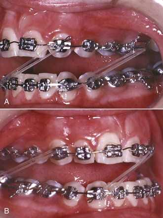
FIGURE 16-2 A and B, Midline correction can be approached with any combination of asymmetric posterior and anterior diagonal elastics. In this patient, a combination of Class II, Class III, and anterior diagonal elastics are being used (a “parallel elastics” arrangement), with a rectangular archwire in the lower arch and a round wire in the upper arch, attempting to shift the maxillary arch to the right.
An important consideration in dealing with midline discrepancies is the possibility of a mandibular shift contributing to the discrepancy. This can arise easily if a slight discrepancy in the transverse position of posterior teeth is present. For instance, a slightly narrow maxillary right posterior segment can lead to a shift of the mandible to the left on final closure, creating the midline discrepancy. The correction in this instance, obviously, must include some force system to alter the transverse arch relationships (usually careful coordination of the maxillary and mandibular archwires, perhaps reinforced by a posterior cross-elastic). Occasionally, the entire maxillary arch is slightly displaced transversely relative to the mandibular arch so that with the teeth in occlusion, relationships are excellent, but there is a lateral shift to reach that position. Correction again would involve posterior cross-elastics but in a parallel pattern (i.e., from maxillary lingual to mandibular buccal on one side and the reverse on the other side; see Figure 16-2).
Tooth Size Discrepancies
Tooth size discrepancy must be taken into account when treatment is planned initially, but many of the steps to deal with these problems are taken in the finishing stage of treatment. Reduction of interproximal enamel (stripping) is the usual strategy to compensate for discrepancies caused by excess tooth size. When the problem is tooth size deficiency, it is necessary to leave space between some teeth, which may or may not ultimately be closed by restorations. As a general guideline, a 2 mm tooth size discrepancy noted from Bolton analysis is the threshold for clinical significance3 (i.e., that large a discrepancy predicts that steps to deal with it will be required during treatment), but at the finishing stage, you get to see how accurate the prediction really was.
One of the advantages of a bonded appliance is that interproximal enamel can be removed at any time. When stripping of enamel is part of the original treatment plan, most of the enamel reduction should be done initially, but final stripping can be deferred until the finishing stage. This procedure allows direct observation of the occlusal relationships before the final tooth size adjustments are made. A topical fluoride treatment always is recommended immediately after stripping is done.
Tooth size problems often are caused by small maxillary lateral incisors. Leaving a small space distal to the lateral incisor can be esthetically and functionally acceptable, but a composite resin buildup usually is the best plan for small incisors (Figure 16-3). Precise finishing is easier if the buildup is done during the finishing stage of the orthodontic treatment. This can be accomplished simply by removing the bracket from the small tooth or teeth for a few hours while the restoration is done, then replacing the bracket and archwires (but bonding to a laminate may damage the surface, so a buildup to establish tooth size is okay, but a laminate should be delayed). If the restoration is delayed until the orthodontics is completed, it should be done as soon as possible after the patient is in retention. This requires an initial retainer to hold the space, and a new retainer immediately after the restoration is completed. The main reason for waiting until after the orthodontic appliance has been removed would be to allow any gingival inflammation to resolve itself.4
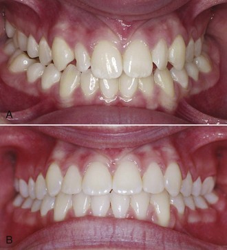
FIGURE 16-3 Small maxillary lateral incisors create tooth-size discrepancy problems that may become apparent only late in treatment. A, Small maxillary lateral incisors, one of which is distorted, prior to treatment. B, After treatment, in which space was created mesial and distal to the laterals so that laminates could be placed to bring the teeth to normal size and appearance.
More generalized small deficiencies can be masked by altering incisor position in any of several ways. To a limited extent, torque of the upper incisors can be used to compensate: leaving the incisors slightly more upright makes them take up less room relative to the lower arch and can be used to mask large upper incisors, while slightly excessive torque can partially compensate for small upper incisors. These adjustments require third-order bends in the finishing archwires. It is also possible to compensate by slightly tipping teeth or by finishing the orthodontic treatment with mildly excessive overbite or overjet, depending on the individual circumstances.5
Root Paralleling
In the Begg technique (see Figure 16-1), the moments necessary for root positioning were generated by adding auxiliary springs into the vertical slot of the Begg (ribbon arch) bracket. In most instances, a heavier (20 mil) archwire replaced the 16 mil archwire used as a base arch up to that point to provide greater stability. Root paralleling was accomplished by placing an uprighting spring in the vertical slot and hooking it beneath the archwire. Since root-paralleling forces are also crown-separating forces, it was important to tie the crowns together across extraction sites. In the modified Begg technique using the Tip-Edge appliance, root paralleling is accomplished with uprighting springs, very much as it was with traditional Begg treatment. The rectangular wire is used primarily for torque (faciolingual root movement), not the mesiodistal root movement needed for root paralleling after teeth were allowed to tip during space closure.
During space closure with the edgewise appliance, it is almost always a goal of treatment to produce bodily tooth movement during space closure, preventing the crowns from tipping toward each other. If proper moment-to-force ratios have been used, little if any root paralleling will be necessary as a finishing procedure. On the other hand, it is likely that at least a small amount of tipping will occur in some patients and therefore some degree of root paralleling at extraction sites often will be necessary. If brackets were not oriented correctly on maxillary lateral incisors and premolars in both arches (the usual problem areas), root separation or paralleling may be needed in nonextraction cases. It is wise to obtain a panoramic radiograph toward the end of the second stage of typical treatment to check for both root positioning errors and root resorption that might dictate ending treatment early.
Exactly the same approach used for root positioning in Begg technique can be employed with the edgewise appliance if it includes a vertical slot behind the edgewise bracket that allows an uprighting spring to be inserted and hooked beneath a base archwire. When only steel archwires were available, this approach often was used, but in contemporary edgewise practice, it has been almost totally abandoned in favor of angulated bracket slots that produce proper root paralleling when a flexible full-dimension rectangular wire is placed.
With the 18-slot appliance, the typical finishing archwire is either 17 × 22 or 17 × 25 steel. These wires are flexible enough to engage narrow brackets even if mild tipping has occurred, and the archwire will generate the necessary root paralleling moments. If a greater degree of tipping has occurred, a more flexible full-dimension rectangular archwire is needed. To correct more severe tipping, a 17 × 25 beta-Ti (TMA) or even a 17 × 25 nickel–titanium (M-NiTi, not superelastic NiTi [A-NiTi]) wire might be needed initially, with a steel archwire used for final expression of torque.
With wider 22-slot brackets on the canines and premolars and with the use of sliding rather than loop mechanics to close extraction sites, there is usually even less need for root paralleling as a finishing procedure. But with 22-slot brackets, if teeth have tipped even slightly into an extraction space or if other root-positioning is needed, steel archwires (19 × 25 steel, for instance) are much too stiff. A 21 × 25 beta-Ti wire is the best choice for a finishing archwire under most circumstances, and if significant root positioning is needed, 21 × 25 M-NiTi should be used first.
Although superelastic NiTi (A-NiTi) wires perform much better than elastic NiTi (M-NiTi) wires in alignment, this is not true of their performance as rectangular finishing wires. The great advantage of A-NiTi is its very flat load-deflection curve, which gives it a large range. In the finishing stage, however, appropriate stiffness at relatively small deflections, rather than range, is the primary consideration. A-NiTi wires usually deliver less force than their M-NiTi counterparts (this will depend on how the manufacturer manipulated the wire [see Chapter 9]), and if rectangular A-NiTi is used in the finishing stage, the wire’s properties in both bending and torsion must be considered in the choice of the wire. M-NiTi almost always is the better choice for rectangular nickel–titanium wires. Occasionally, a severely tipped tooth will be encountered (almost always because of a bracket positioning error), and a longer range of action is needed. This may indicate using a rectangular A-NiTi wire initially, then M-NiTi. An alternative, usually practical only if the edgewise brackets have a vertical slot or tube, is an auxiliary root-uprighting spring (Figure 16-4).
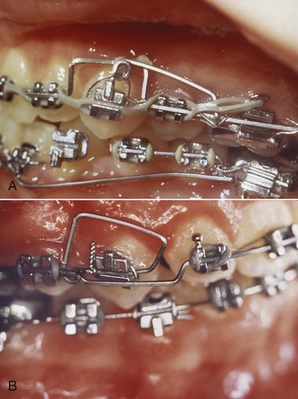
FIGURE 16-4 A, An uprighting spring to the maxillary canine, placed in a vertical tube incorporated into the canine bracket, in segmented arch technique. Note that the base archwire bypasses the canine. B, An auxiliary root positioning spring welded to the base archwire and tied into the edgewise bracket slot of a maxillary canine, with the base archwire bypassing the canine. Both approaches remain useful to correct severe root paralleling problems, but with the introduction of contemporary straight-wire appliances, use of auxiliary uprighting springs in edgewise technique has largely been replaced by resilient NiTi or beta-Ti continuous archwires in preangulated brackets. (Courtesy Dr. C. Burstone.)
A root-paralleling moment is a crown-separating moment in edgewise technique just as it is in Begg or any other technique. It is important to remember this effect. Either the teeth must be tied together or the entire archwire must be tied back against the molars (Figure 16-5) to prevent spaces from opening. Not only extraction sites but also maxillary incisors must be protected against this complication. When a full-dimension rectangular wire is placed in the maxillary arch, spaces are likely to open between the incisors in nonextraction as well as extraction cases. Tying the maxillary incisors together, which can be done conveniently with a segment of elastomeric chain from the mesial bracket of one upper lateral incisor across to the mesial bracket of the other, is necessary during finishing.
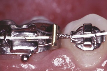
FIGURE 16-5 A rectangular archwire that incorporates active root paralleling moments or torque must be tied back against the molar teeth to prevent space from opening within the arch. If the ligature used to tie back the archwire is cabled forward and also used to tie the second premolar, the tieback is less likely to come loose.
Torque
Lingual Root Torque of Incisors
If protruding incisors tipped lingually while they were being retracted, lingual root torque as a finishing procedure may be required. In the Begg technique, the incisors are deliberately tipped back during the second stage of treatment, and lingual root torque is a routine part of the third stage of treatment. Like root paralleling, this is accomplished with an auxiliary appliance that fits over the main or base archwire. The torquing auxiliary is a “piggyback arch” that contacts the labial surface of the incisors near the gingival margin, creating the necessary couple with a moment arm of 4 to 5 mm (see Figure 16-1). These piggyback torquing arches can be used in edgewise technique in the same way (see Figure 14-30, D). Although they come in a number of designs, the basic principle is the same: the auxiliary arch, bent into a tight circle initially, exerts a force against the roots of the teeth as it is partially straightened out to normal arch form (Figure 16-6).
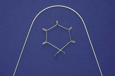
FIGURE 16-6 Torquing auxiliary archwires exert their effect when the auxiliary, originally bent in a tight circle as shown, is forced to assume the form of a base archwire over which it will be placed. This tends to distort the base archwire, which therefore should be relatively heavy—at least 18 mil steel.
A torquing force to move the roots lingually is also, of course, a force to move the crowns labially (see Figure 15-24). In a typical patient with a Class II malocclusion, anchorage is required to maintain overjet correction while upper incisor roots are torqued lingually. For that reason, Class II elastics are likely to be necessary when active lingual root torque is needed during the final stage of Class II treatment.
With a modern edgewise appliance, only moderate additional incisor torque should be necessary during the finishing stage. With the 18-slot appliance, a 17 × 25 steel archwire has excellent properties in torsion, and torque with this archwire is entirely feasible. Building torque into the bracket slot initially means that it is unnecessary to place torquing bends in the archwire, making the accomplishment of torque as a finishing procedure relatively straightforward.
With the 22-slot appliance, full-dimension steel rectangular wires are far too stiff for effective torquing (see Figure 9-11). If incisors have been allowed to tip lingually too much, as can happen in the correction of maxillary incisor protrusion, correcting this merely by placing a rectangular steel archwire is not feasible. Prior to brackets with built-in torque and titanium archwires, torquing auxiliaries were commonly used with the 22-slot appliance. One of the great virtues of torque-slot brackets is that tipping of incisors, for the most part, can be prevented during retraction and space closure. In addition, full-dimension M-NiTi or beta-Ti archwires can be used to torque incisors with 22-slot brackets (provided the brackets have torque built in), further reducing any need for auxiliary arches. For these reasons, torquing auxiliaries for 22-slot edgewise have almost disappeared from contemporary use, except when upright incisors are to be corrected by tipping the crowns facially.
One torquing auxiliary, however, deserves special mention: the Burstone torquing arch (Figure 16-7). It can be particularly helpful in patients with Class II, division 2 malocclusion whose maxillary central incisors are severely tipped lingually and require a long distance of torquing movement, while the lateral incisors need little if any torque. Because of the long lever arm, this is the most effective torquing auxiliary for use with the edgewise appliance. It is equally effective with the 18- or 22-slot appliance. If all four incisors need considerable torque, a wire spanning from the molar auxiliary tube to the incisors, with a V-bend so that the incisor segment receives the greater moment, is a highly efficient approach.6
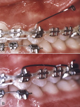
FIGURE 16-7 The Burstone torquing auxiliary (also see Figure 9-44) is particularly useful in Class II division 2 cases in which maxillary central incisors need a large amount of torque. The torquing auxiliary is full-dimension steel wire (21 × 25 or 17 × 25, in 22- or 18-slot brackets, respectively) that fits in the brackets only on the incisors. It can be used only on the centrals or on the centrals and laterals, as shown here. The base arch (preferably also full-dimension rectangular wire) extends forward from the molars through the canine or lateral incisor brackets, then steps down and rests against the labial surface of the teeth to be torqued. When the torquing auxiliary is passive (A), its long posterior arms are up in the buccal vestibule. It is activated (B) by pulling the arms down and hooking them beneath the base archwire mesial to the first molar. The segment of the base arch that rests against the labial surface of the central incisors prevents the crowns from going forward, and the result is efficient lingual root torque.
Three factors determine the amount of torque that will be expressed by any rectangular archwire in a rectangular slot: the torsional stiffness of the wire, the inclination of the bracket slot relative to the archwire, and the tightness of the fit between the archwire and the bracket. The variations in torque prescriptions in contemporary edgewise brackets are discussed in Chapter 10. These variations largely reflect different determinations of the average contour of the labial and buccal surfaces of the teeth, but some differences are also related to the expected fit of archwires.
With the 18-slot appliance, it is assumed that the rectangular archwires used for finishing will fit tightly in the bracket slot (i.e., that the finishing archwires will have a minimum dimension of 17 mil). With the 22-slot appliance, on the other hand, some prescriptions have extra built-in torque to compensate for rectangular finishing archwires that will have more clearance. Torque will not be expressed to the same extent with a 19 × 25 wire in a 22-slot bracket as with a 17 × 25 wire in an 18-slot bracket. The difference amounts to several degrees of difference in incisor inclination. The “effective torque” of various wire-bracket combinations is shown in Table 16-1. Obviously, when the torque prescription for a bracket is established, it is important to know what finishing wires are intended.
TABLE 16-1
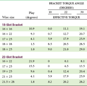
Based on nominal wire and/or slot sizes; actual play is likely to be greater.
From Semetz: Kieferorthop Mitteil 7:13-26, 1993.
For full expression of the torque built into brackets in the 22-slot appliance, the best finishing wire usually is 21 × 25 beta-Ti. This wire’s torsional stiffness is less than that of 17 × 25 steel (see Figure 9-11), but the shorter interbracket distances with 22-slot twin brackets bring its performance in torsion close to that of the smaller steel wire. Braided rectangular steel wires are available in a variety of stiffnesses, and the stiffest of these in 21 × 25 dimension also can be useful in 22-slot finishing. A solid 21 × 25 steel wire cannot be recommended because of its stiffness and the resulting extremely high forces and short range of action. If a solid steel wire of this size is used (the major reason would be surgical stabilization), it should be preceded by 21 × 25 beta-Ti.
Some clinicians are reluctant to use full-dimension archwires in 22-slot brackets, but it should be kept in mind that full torque expression will never be achieved with undersized wires without extreme bracket prescriptions or placing major twist bends in the wires, and even then it is difficult to obtain adequate torque routinely.
Buccal Root Torque of Premolars and Molars
It should be kept in mind that buccal root torque of maxillary premolars can be an important esthetic consideration in positioning these teeth. It is surprisingly common that at the end of fixed appliance treatment, maxillary canines and premolars are tipped facially because the prescription in many modern brackets provides negative torque (lingual crown torque) for these teeth (see Table 10-3). Zachrisson has pointed out that this negatively affects smile esthetics, especially in patients with narrow and tapered arch forms, by making the canines less prominent and causing the first premolars to almost disappear on smile. To obtain a broader and more pleasing smile, the solution is not to further expand across the premolars, but to use buccal crown torque so that the crowns are uprighted (Figures 16-8 and 16-9).7 This gives the appearance of a broader smile without the risk of relapse that accompanies arch expansion. Long-term data indicate that the inclinations of these teeth remain the way they were at the end of treatment, so changing the torque is stable.8
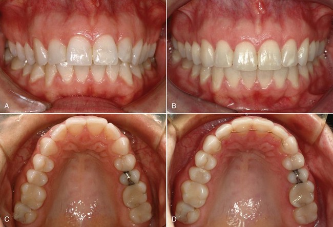
FIGURE 16-8 For this patient the maxillary arch looks narrow because the canine and premolars are tipped lingually, but significant expansion across the canines and premolars is not necessary. Instead, torque to the canines and especially to the premolars so that these teeth are uprighted faciolingually without major expansion improves the appearance of the dentition, and the torque changes are stable in a way that expansion is not. A and B, Prior to treatment. C and D, After treatment that included torque to upright the canines and premolars. (Courtesy Dr. B. Zachrisson.)

FIGURE 16-9 A and B, Same patient as Figure 16-8. Note the improvement in smile esthetics and “width of the smile” produced by torque to the canines and premolars. This can be obtained most readily by changing the bracket prescription to decrease or eliminate the negative torque in most current prescription brackets for maxillary canines and premolars (see Table 10-3). (Courtesy Dr. B. Zachrisson.)
Uprighting the premolars in this way does elongate their lingual cusps and potentially could lead to occlusal interferences that would be difficult for patients to tolerate. If this occurs (which is unlikely), reduction of the height of the lingual cusps is indicated.
Correction of Vertical Incisor Relationships
If the first two stages of treatment have been accomplished perfectly, no change in the vertical relationship of incisors will be needed during the finishing stage of treatment. Minor adjustments often are needed, however, and major ones occasionally are required. At this stage, anterior open bite is more likely to be a problem than residual excessive overbite, but either may be encountered.
Excessive Overbite
Before attempting to correct excess overbite at the finishing stage of treatment, it is important to carefully assess why the problem exists and particularly to evaluate two things: (1) the vertical relationship between the maxillary lip and maxillary incisors and (2) anterior face height. If the display of the maxillary incisors on smile is appropriate, it is important to maintain this and make any overbite correction by repositioning the lower incisors. If display is excessive, intrusion of the upper incisors would be indicated. If face height is short, elongating the posterior teeth slightly (almost always, the lower posterior teeth) would be acceptable; if face height is long, intrusion of incisors would be needed.
If intrusion is indicated and a rectangular finishing archwire is already in place, the simplest approach is to cut this archwire distal to the lateral incisors and install an auxiliary intrusion arch (see Figure 14-24). Remember that when a maxillary auxiliary intrusion arch is used, a stabilizing transpalatal lingual arch may be needed to maintain control of transverse relationships and prevent excessive distal tipping of the maxillary molars. The greater the desired vertical change in incisor position, the more important it will be to have a stabilizing lingual arch in place and vice versa. Small corrections during finishing usually do not require placing a lingual arch.
Alternatively, if slight elongation of the posterior teeth is indicated, step bends in a flexible archwire would be satisfactory. The intermediate archwire before the final torquing archwire is the one for implementation of these step bends (17 × 25 TMA with the 18-slot appliance, 21 × 25 M-NiTi with the 22-slot appliance). An auxiliary depressing arch for overbite correction can be effective, but only if the base archwire is a relatively small round wire (see Chapter 14), so this is not the preferred approach for a modest amount of final overbite correction.
Anterior Open Bite
As with deep bite, it is important to analyze the source of the difficulty if an anterior open bite persists at the finishing stage of treatment, and as with deep bite, the relationship of the upper incisors to the lip and anterior face height are critical in determining what to do. If the open bite results from excessive eruption of posterior teeth, whether from a poor growth pattern or excessive use of interarch elastics (Figure 16-10), correcting it at the finishing stage can be extremely difficult. The most effective approach to intrusion of posterior teeth is skeletal anchorage. Placing bone screws at the finishing stage to accomplish this implies that the earlier stages of treatment were not completed satisfactorily, but this might be necessary in some patients with a severe long face pattern of growth.
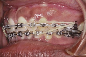
FIGURE 16-10 Class III elastics tend to extrude upper molars, and their use can lead rapidly to the development of anterior open bite. Using a triangular Class III elastic, as shown here, helps to control the open bite tendency. Class II elastics can do the same thing by extruding lower molars, and the bite opening can be reduced by a similar triangulation. Use of Class III or Class II elastics, of course, presupposes that some elongation of the molars is acceptable.
If no severe problems with the pattern of facial growth exist, however, a mild open bite at the finishing stage of treatment often is due to an excessively level lower arch. This condition is managed best by elongating the lower but not the upper incisors, thereby creating a slight curve of Spee in the lower arch. Because of the stiffness of the rectangular archwires used for finishing, even with 18-slot edgewise, it is futile to use vertical elastics to deepen the bite without altering the form of the archwires. Steps in an appropriately flexible lower archwire, while maintaining a stiffer upper wire, can be effective when supplemented with light vertical elastics (Figure 16-11). Obviously, if display of the upper incisors is inadequate, elongation of those teeth to close the bite would be indicated, and the same approach with the flexible/stabilizing archwires reversed would be indicated. Elongating the lower incisors to close a moderate anterior open bite is a quite stable procedure. Elongating the upper incisors is less stable, and compromises facial esthetics if it makes them too prominent. This should be kept in mind when vertical repositioning of incisors is planned.
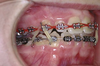
FIGURE 16-11 Vertical elastics, bilaterally in the triangular hook-up shown here in conjunction with an anterior box elastic or as an anterior box elastic alone, can be used to help close a mild anterior open bite at the end of treatment, but this is effective only if the archwires are contoured to allow the tooth movement. Elastics cannot overpower a stiff archwire that is maintaining the open bite.
Final “Settling” of Teeth
At the conclusion of treatment with the edgewise appliance, it is not uncommon for a full-dimension rectangular archwire, no matter how carefully made, to hold some teeth slightly out of occlusion. The more precisely a stiff finishing archwire fits the brackets and the more bends that it requires to compensate for bracket positioning, the more likely that some teeth will be almost but not quite in occlusion. This phenomenon was recognized by the pioneers with the edgewise appliance, who coined the term “arch-bound” to describe it. They found that with precisely fitting wires, it was almost impossible to get every tooth into solid occlusion, although one could come close. From the early days of edgewise treatment to the present, therefore, a final step of bringing the teeth into occlusion, appropriately called “settling” of the teeth, has been needed.
Methods for Settling the Teeth
There are three ways to settle the occlusion:
1. By replacing the rectangular archwires at the very end of treatment with light round arches that provide some freedom for movement of the teeth (16 mil in the 18-slot appliance, 16 or 18 mil in the 22-slot appliance) and using light vertical elastics to bring the teeth together
2. Using laced posterior vertical elastics after removing the posterior segments of the archwires
3. After the bands and brackets have been removed, using a tooth positioner
Replacing full-dimension rectangular wires with light round wires at the very end of treatment was the original method for settling, recommended by Tweed in the 1940s and perhaps by other edgewise pioneers earlier. These light final arches must include any first- or second-order bends used in the rectangular finishing arches. It is usually unnecessary for the patient to wear light posterior vertical elastics during this settling, but they can be used if needed. These light arches will quickly settle the teeth into final occlusion and should remain in place for only a few weeks at most.
The difficulty with undersized round wires at the end of treatment is that some freedom of movement for settling of posterior teeth is desired, but precise control of anterior teeth is lost as well. It was not until the 1980s that orthodontists realized the advantage of removing only the posterior part of the rectangular finishing wire, leaving the anterior segment (typically canine-to-canine) in place, and using laced elastics to bring the posterior teeth into tight occlusion (Figure 16-12).9 This method sacrifices a large degree of control of the posterior teeth and therefore should not be used in patients who had major rotations or posterior crossbite. For the majority of patients who had well-aligned posterior teeth from the beginning, however, this is a remarkably simple and effective way to settle the teeth into their final occlusion. It is the last step in active treatment for the majority of patients at present.
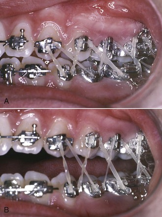
FIGURE 16-12 A and B, Use of laced elastics for settling the teeth into final occlusion at the end of treatment. The elastics can be used either with light round archwires or (usually preferred) with rectangular segments in the anterior brackets and no wire at all posteriorly. The last step in treatment then becomes cutting the rectangular finishing archwires distal to the lateral incisors or canines and removing the posterior segments.
A typical arrangement is to use light  inch elastics, with a Class II or Class III direction, depending on whether slightly more correction is desired. An alternative is to use a pair of
  or
or  inch elastics on both sides in a vertical triangle. These elastics should not remain in place for more than 2 weeks, and 1 week usually is enough to accomplish the desired settling. At that point, the fixed appliances should be removed and the retainers placed.
Because it is used after the orthodontic appliance has been removed, the use of a tooth positioner for final settling is discussed after the section below on removing bands and bonded brackets.
Control of Rebound and Posturing
After Class II or Class III correction, particularly if interarch elastics have been used, the teeth tend to rebound back toward their initial position despite the presence of rectangular archwires.
Because of this, it is important to slightly overcorrect the occlusal relationships. In a typical Class II anterior deep bite patient, the teeth should be taken to an end-to-end incisor relationship, with both overjet and overbite totally eliminated, before the headgear or elastic forces are discontinued. This provides some latitude for the teeth to rebound before final settling is accomplished.
Sometimes when Class II elastics are used, patients begin to posture the mandible forward so that the occlusion looks more corrected than it really is—and if the appliances are removed at that point, they are likely to slip back toward a Class II molar relationship and increased overjet. This should not be confused with rebound, which is due only to tooth movement. Rebound is a 1 to 2 mm phenomenon; posturing can lead to 4 to 5 mm relapse, and obviously it is important to detect it and continue treatment to a true correction.
These considerations lead to the guidelines for finishing treatment when interarch elastics have been used:
1. When an appropriate degree of overcorrection has been achieved, the force used with the elastics should be decreased while the light elastics are continued full time for another appointment interval;
2. At that point, interarch elastics should be discontinued, 4 to 8 weeks before the orthodontic appliances are to be removed, so that changes due to rebound or posturing can be observed. It is better to tell the patient that he or she is getting a vacation from the elastics and that some further elastic wear may be necessary if changes are observed, rather than saying that elastics are no longer needed. If changes do occur, that makes it easier for patients to accept that the vacation is over and another period of elastics is needed.
3. If the occlusion is stable, as a final step in treatment, the teeth should be brought into a solid occlusal relationship without heavy archwires present, using one of the methods described above.
Removal of Bands and Bonded Attachments
Removal of bands is accomplished by breaking the cement attachment and then lifting the band off the tooth, which sounds simpler than it is in some instances. For upper molar and premolar teeth, a band-removing instrument is placed so that first the lingual, then the buccal surface is elevated (Figure 16-13). A welded lingual bar is needed on these bands to provide a point of attachment for the pliers if lingual hooks or cleats are not a part of the appliance. For the lower posterior teeth, the sequence of force is just the reverse: the band remover is applied first on the buccal, then the lingual surface.
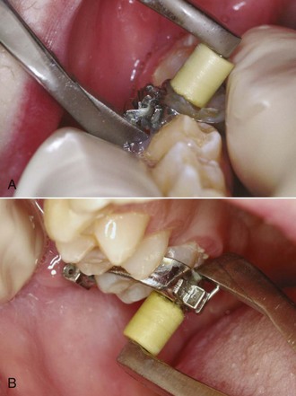
FIGURE 16-13 Removal of molar bands with band-removing pliers. A, Lower posterior bands are removed primarily with pressure from the buccal surface. B, Upper posterior bands are removed with pressure primarily against the lingual surface, which is easier when a lingual tube (as seen here), cleat, or other attachment was welded to the band initially.
Bonded brackets must be removed, insofar as possible, without damaging the enamel surface. This is done by creating a fracture within the resin bonding material or between the bracket and the resin and then removing the residual resin from the enamel surface. With metal brackets, applying a cutting pliers to the base of the bracket so that the bracket bends (Figure 16-14) is the safest method. This has the disadvantage of destroying the bracket, which otherwise could be reused, but protecting the enamel usually is a more important consideration.
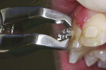
FIGURE 16-14 Removal of bonded brackets. A special pliers can be used to fracture the bonding resin, which usually results in much of the resin left on the tooth surface. This works particularly well with twin brackets. The advantage of this method is that the bracket usually is undamaged; the disadvantage is heavy force that may cause enamel damage. The alternative is to use a cutter to distort the bracket base. The first approach is more compatible with recycling of brackets, but the second is safer and usually leaves less resin to remove from the tooth surface.
Enamel damage from debonding metal brackets is rare, but there have been a number of reports of enamel fractures and removal of chunks of enamel when ceramic brackets are debonded (see Chapter 10 for a more detailed discussion). It also is easy to fracture a ceramic bracket while attempting to remove it, and if that happens, large pieces of the bracket must be ground away with a diamond stone in a handpiece. These problems arise because ceramic brackets have little or no ability to deform—they are either intact or broken. Shearing stresses are applied to the bracket to remove it, and the necessary force can become alarmingly large.
There are three approaches to these problems in debonding ceramic brackets:
1. Modify the interface between the bracket and the bonding resin to increase the chance that when force is applied, the failure will occur between the bracket and the bonding material. Most of the ceramic brackets now on the market have an interface designed to make removal easier. Chemical bonds between the bonding resin and the bracket can be too good, and most manufacturers now have weakened them or abandoned chemical bonding altogether.
2. Use heat to soften the bonding resin, so that the bracket can be removed with lower force.
3. Modify the bracket so that it breaks predictably when debonding force is applied. One advantage of a metal slot in a ceramic bracket is that then the bracket can be engineered to fracture in the slot area, which makes it much easier to remove.
Electrothermal and laser instruments to heat ceramic brackets for removal now are available. There is no doubt that less force is needed when the bracket is heated, and research findings indicate that there is little patient discomfort and minimal risk of pulpal damage.10 Nevertheless, the ideal solution would be to perfect the third approach so that ceramic brackets can be debonded without heating as readily as metal ones.
Cement left on the teeth after debanding can be removed easily by scaling, but residual bonding resin is more difficult to remove. The best results are obtained with a 12-fluted carbide bur at moderate speeds in a dental handpiece (Figure 16-15).11 This bur cuts resin readily but has little effect on enamel. Topical fluoride should be applied when the cleanup procedure has been completed, however, since some of the fluoride-rich outer enamel layer may be lost with even the most careful approach.
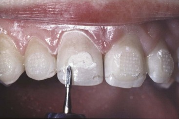
FIGURE 16-15 Upon debonding, the bond failure usually occurs between the base of the bracket and the resin, leaving excess resin on the tooth. Removing excess bonding resin is best accomplished with a smooth 12-fluted carbide bur, followed by pumicing. The carbide bur is used with a gentle wiping motion to remove the resin.
Positioners for Finishing
An alternative to segmental elastics or light round archwires for final settling is a full-arch tooth positioner. A positioner is most effective if it is placed immediately on removal of the fixed orthodontic appliance. Normally, it is fabricated by removing the archwires 4 to 6 weeks before the planned removal of the appliance, taking impressions of the teeth and a registration of occlusal relationships, and then resetting the teeth in the laboratory, incorporating the minor changes in position of each tooth necessary to produce appropriate settling (Figure 16-16). Using a facebow transfer to mount the casts for the positioner setup to fabricate a “gnathologic positioner” does not seem to be necessary for patients with normal jaw relationships. All erupted teeth should be included in the positioner to prevent supereruption. As part of the laboratory procedure, bands and brackets are trimmed away, and any band space is closed.

FIGURE 16-16 Use of a positioner for finishing. A, Dental casts after appliance removal. B, The positioner setup. Often the positioner impression is taken one month before debanding, with bands and brackets carved off the teeth in the laboratory, so the positioner can be delivered immediately after the appliance is removed. C, Transparent positioner on setup. D, Maxillary occlusal view of the positioner. Note the clasps in the premolar region that help to prevent space from opening. Their use is particularly important when a positioner is used in a maxillary premolar extraction case.
This indirect approach allows individual tooth positions to be adjusted with considerable precision, bringing each tooth into the desired final relationship. The positioning device is then fabricated by forming an elastic material (formerly rubber, now usually polyurethane) around the repositioned and articulated casts, producing a device with the inherent elasticity to move the teeth slightly to their final position as the patient bites into it.
The use of a tooth positioner rather than final settling archwires has two advantages: (1) it allows the fixed appliance to be removed somewhat more quickly than otherwise would have been the case (i.e., some finishing that could have been done with the final archwires can be left to the positioner) and (2) it serves not only to reposition the teeth but also to massage the gingiva, which is almost always at least slightly inflamed and swollen after comprehensive orthodontic treatment. The gingival stimulation provided by a positioner is an excellent way to promote a rapid return to normal gingival contours (Figure 16-17).
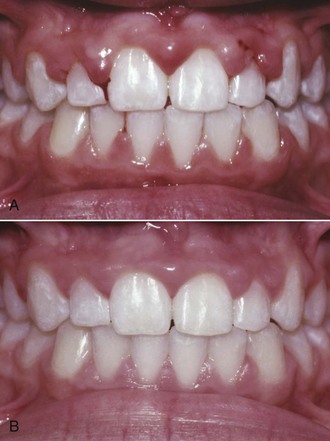
FIGURE 16-17 Gingival improvement with positioner wear. A, Swollen maxillary papillae immediately after band removal, just before placement of an immediate positioner. B, Two weeks later. This degree of gingival swelling and puffiness occurs only rarely during fixed appliance treatment, but when it does, a positioner is one of the best means to resolve it.
The use of positioners for finishing also has significant disadvantages. First of all, these appliances require a considerable amount of laboratory fabrication time and therefore are expensive. Second, settling with a positioner tends to increase overbite more than the equivalent settling with light elastics. This is a disadvantage in patients who had a deep overbite initially but can be advantageous if the initial problem was an anterior open bite. Third, a positioner does not maintain the correction of rotated teeth well, which means that minor rotations may recur while a positioner is being worn. Finally, good cooperation is essential.
With modern edgewise appliances, the first advantage is not nearly so compelling as it was previously. It is an error to remove a modern fixed appliance early and depend on a positioner to accomplish more than minimal settling of the occlusion. At present, there are two main indications for use of a positioner: (1) a gingival condition with more than the usual degree of inflammation and swelling at the end of active orthodontics or (2) an open bite tendency, so that settling by mild depression rather than elongation of posterior teeth is needed. Severe malalignment and rotated teeth, a deep bite tendency, and an uncooperative patient are contraindications for positioner use.
A positioner should be worn by the patient at least 4 hours during the day and during sleep. Since the amount of tooth movement tends to decline rapidly after a few days of use, an excellent schedule is to remove the orthodontic appliances, clean the teeth and apply a fluoride treatment, and place the positioner immediately, asking the patient to wear it as nearly full time as possible for the first 2 days. After that, it can be worn on the usual night-plus-4 hours schedule.
As a general rule, a tooth positioner in a cooperative patient will produce any changes it is capable of within 2 to 3 weeks. Final (posttreatment) records and retainer impressions can be taken 2 or 3 weeks after the positioner is placed. Beyond that time, if the positioner is continued, it is serving as a retainer rather than a finishing device—and positioners, even gnathologic positioners, are not good retainers (see Chapter 17).
Special Finishing Procedures to Avoid Relapse
Relapse after orthodontic treatment has two major causes: (1) continued growth by the patient in an unfavorable pattern and (2) tissue rebound after the release of orthodontic force.
Control of Unfavorable Growth
Changes resulting from continued growth in a Class II, Class III, deep bite, or open bite pattern contribute to a return of the original malocclusion and so are relapse in that sense. These changes are due to the pattern of skeletal growth, not just to tooth movement. Controlling this type of relapse requires a continuation of active treatment after the fixed appliances have been removed.
This “active retention” takes one of two forms. One possibility is to continue extraoral force in conjunction with orthodontic retainers (high-pull headgear at night, for instance, in a patient with a Class II open bite growth pattern). The other, which often is more acceptable to the patient, is to use a functional appliance rather than a conventional retainer after the completion of fixed appliance therapy. This important subject is discussed in more detail in Chapter 17.
Control of Soft Tissue Rebound
A major reason for retention is to hold the teeth until soft tissue remodeling can take place. Even with the best remodeling, however, some rebound from the application of orthodontic forces occurs, and indeed the tendency for rebound after interarch elastics are discontinued has already been discussed. There are two ways to deal with this phenomenon: (1) overtreatment, so that any rebound will only bring the teeth back to their proper position, and (2) adjunctive periodontal surgery to reduce rebound from elastic fibers in the gingiva.
Overtreatment
Since it can be anticipated that teeth will rebound slightly toward their previous position after orthodontic correction, it is logical to position them at the end of treatment in a somewhat overtreated position. Only a small degree of overtreatment is compatible with precise finishing of orthodontic cases as described previously, but it is nevertheless possible to apply this principle during the finishing phase of treatment. Consider three specific situations:
1. Correction of Class II or Class III malocclusion. Overtreatment of 1 to 2 mm to accommodate for the expected rebound after Class II or Class III correction has already been discussed. As long as the appliance is in place, elastic wear can be reinstituted to obtain a complete correction if there is excessive rebound (or if posturing is detected).
2. Crossbite correction. Whatever the mechanism used to correct crossbite, it should be overcorrected by at least 1 to 2 mm before the force system is released. If the crossbite is corrected during the first stage of treatment, as should be the case, the overcorrection will gradually be lost during succeeding phases of treatment, but this should improve stability when transverse relationships are established precisely during the finishing phase.
3. Irregular and rotated teeth. Just as with crossbites, irregularities and rotations can be overcorrected during the first phase of treatment, carrying a tooth that has been lingually positioned slightly too far labial, for instance, and vice versa. It is wise to hold the teeth in a slightly overcorrected position for at least a few months, during the end of the first stage of treatment and the second stage. As a general rule, however, it is not wise to build this overcorrection into rectangular finishing archwires.
Similarly, a tooth being rotated into position in the arch can be over-rotated. Maintaining an over-rotated position can be done by adjusting the wings of single brackets, or by maintaining a rotation wedge in place with twin brackets. Maintaining overcorrected labiolingual positions of incisors is done readily with first-order bends in working archwires. Rotated teeth should be maintained in an overcorrected position as long as possible, but even then, these teeth are often candidates for the periodontal procedures described below.
Adjunctive Periodontal Surgery
Sectioning of Elastic Gingival Fibers: A major cause of rebound after orthodontic treatment is the network of elastic supracrestal gingival fibers. As teeth are moved to a new position, these fibers tend to stretch, and they remodel very slowly. If the pull of these elastic fibers could be eliminated, a major cause of relapse of previously irregular and rotated teeth should be eliminated. In fact, if the supracrestal fibers are sectioned and allowed to heal while the teeth are held in the proper position, relapse caused by gingival elasticity is greatly reduced.
Surgery to section the supracrestal elastic fibers is a simple procedure that does not require referral to a periodontist unless possible gingival recession is an esthetic concern. It can be carried out by either of two approaches. The first method, originally developed by Edwards,12 is called circumferential supracrestal fibrotomy (CSF). After infiltration with a local anesthetic, the procedure consists of inserting the sharp point of a fine blade into the gingival sulcus down to the crest of alveolar bone. Cuts are made interproximally on each side of a rotated tooth and along the labial and lingual gingival margins unless, as is often the case, the labial or lingual gingiva is quite thin, in which case this part of the circumferential cut is omitted. No periodontal pack is necessary, and there is only minor discomfort after the procedure.
An alternative method is to make an incision in the center of each gingival papilla, sparing the margin but separating the papilla from just below the margin to 1 to 2 mm below the height of the bone buccally and lingually (Figure 16-18). This modification is said to reduce the possibility that the height of the gingival attachment will be reduced after the surgery, and it is particularly indicated for esthetically sensitive areas (e.g., the maxillary incisor region). Nevertheless, there is little if any risk of gingival recession with the original CSF procedure unless cuts are made across thin labial or lingual tissues. From the point of view of improved stability after orthodontic treatment, the surgical procedures appear to be equivalent.
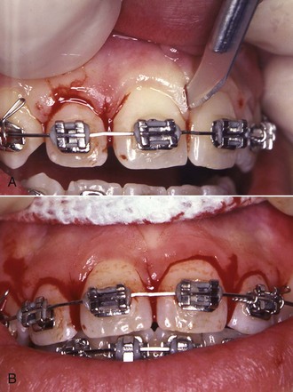
FIGURE 16-18 The “papilla split” procedure is an alternative to the “around the tooth” CSF approach for sectioning gingival circumferential fibers to improve posttreatment stability. It is particularly indicated for esthetically sensitive areas like the maxillary anterior region. Vertical cuts are made in the gingival papillae without separating the gingival margin at the papilla tip. A, The blade inserted to make the vertical cut. B, View at completion of the papilla splits before sutures are placed. Another advantage of this procedure is that it is easier to perform with an orthodontic appliance and archwire in place.
Neither the CSF nor the papilla-dividing procedure should be done until malaligned teeth have been corrected and held in their new position for several months. This means that either the surgery should be done a few weeks before removal of the orthodontic appliance or, if it is performed at the same time the appliance is removed, a retainer must be inserted almost immediately. It is easier to do the CSF procedure after the orthodontic appliances have been removed, although it can be carried out with appliances in place. An advantage of the papilla-dividing procedure may be that it is easier to perform with the orthodontic appliance still in place. The problem with placing a retainer immediately after the surgery is that it is difficult to keep it from contacting soft tissue in a sore area.
Experience has demonstrated that sectioning the gingival fibers is an effective method to control rotational relapse but does not control the tendency for crowded incisors to again become irregular. The primary indication for gingival surgery therefore is a tooth or teeth that were severely rotated. This surgery is not indicated for patients with crowding without rotations.
Micro-Esthetic Procedures in Finishing
Micro-esthetic considerations in the display and shape of the teeth have been discussed previously in Chapter 6. As a general rule, the soft tissue considerations should be dealt with first, and enameloplasty should be deferred until initial alignment has been achieved and rotations have been corrected.
Recontouring the Gingiva to Improve Tooth Proportions and Display
Height–width ratios of the teeth are greatly affected by the extent to which gingiva covers the upper part of the crown, and this issue should be addressed before recontouring of the teeth is done. Note that for the patient shown in Figure 16-19, the height–width ratio of the maxillary incisors was well below the normal proportion because the upper portion of the crowns was covered by gingiva. Careful probing established that removal of the gingiva to the level of the cementoenamel junction was possible, and a diode laser was used to do this. The effect was an improvement in both tooth proportionality and incisor display.
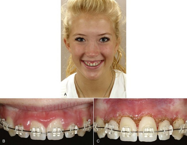
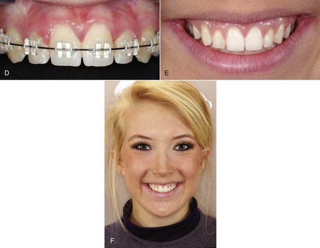
FIGURE 16-19 A, For this patient near the end of orthodontic treatment, the inadequate display of the maxillary incisors was primarily due to short clinical crowns because of gingival overgrowth. B, In this view of the close-up smile, note that the zenith of both central incisor crowns, especially the right central, is too far distal, and that the contour of the gingiva over both lateral incisors is excessive. Probing established that removal of excessive tissue to the level of the cementoenamel junction was possible. C, The appearance of the teeth and gingiva immediately after laser recontouring of the gingiva. D, Two weeks later. E, Three months later, close-up, and (F) full-face smile at end of treatment.
Reshaping the Teeth for Enhanced Esthetics
For many years, dentists have defined tooth shape and morphology in terms of (1) ideal ratios of tooth dimensions, which are affected by the extent to which the gingival tissues cover or expose the crown as discussed above, and (2) definitions of tooth shape and contour. Much of modern esthetic dentistry is based on these dimensions and definitions.13 Identification and treatment of micro-esthetic characteristics can greatly enhance orthodontic outcomes,14,15 and therefore this is an important part of orthodontic diagnosis and treatment.
In general, soft tissue recontouring is done first, often as a first step in treatment. This allows ideal vertical placement of brackets at the beginning of treatment so that gingival margins and placement of incisal edges can be optimized and provides time for healing so that the apparent proportions of the teeth will not be affected by soft tissue changes. Enamel recontouring should not be done until after the initial phase of orthodontic alignment because, if a tooth rotation is corrected, the perception of its width is changed while the height is not, giving a misleading height–width ratio. After alignment, reshaping of the teeth can be carried out as desired but should be completed before the end of the finishing stage of treatment.
Consider the patient shown in Figure 16-20, whose chief concern was protruding teeth. She had been treated as an adolescent to reasonably good occlusion and dental alignment but now wanted enhancement of her appearance on smile.
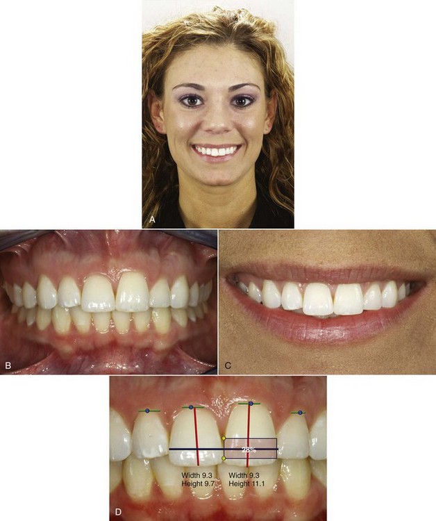
FIGURE 16-20 A, This patient presented with a chief complaint of protruding teeth. She had been treated as a child to a good occlusion and acceptable smile esthetics. B and C, She had reasonably well-aligned teeth with good overbite/overjet and smile arc but (1) disparate incisal edges and gingival margins; (2) a 1:1 height-width ratio for the right central incisor, with a more appropriate 8:10 ratio for the left central; and (3) an excessive gingival embrasure between the centrals, which often is referred to as a “black triangle.” D, Assessment of micro-esthetic characteristics showed that the gingival zeniths (denoted by the green dots) were well placed, being slightly distal to the long axes of the centrals and coincident to the long axes of the lateral incisors. The excessive gingival embrasure and black triangle were the result of the short connector of only 28% (shown by the box over the left central). The ideal connector length should comprise 50% of the central incisor height.
Micro-esthetic considerations on clinical evaluation were
• Vertical height differences for both the maxillary teeth and gingival margins.
• Different height–width ratios for the central incisors.
• Central incisors disproportionately larger than lateral incisors.
• Short connector length between the central incisors. The ideal connector length for these teeth is 50% of the height of the central incisors, and in this case the connector length was only 28%.
• An excessive gingival embrasure between the central incisors, resulting in a “black triangle.”
The micro-esthetic treatment plan and order of treatment (Figure 16-21) was to:
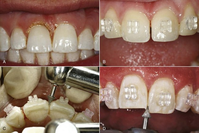
FIGURE 16-21 For the patient shown in Figure 16-20, the height of the right central was shorter than normal, and after periodontal probing demonstrated that adequate tissue could be removed without compromising the gingival attachment, a laser-assisted gingivectomy was carried out. A, Immediately after the laser procedure. A gingival dressing was not needed because of the coagulation created by the laser. B, After initial alignment of the teeth, a fine carbide bur was used to lengthen the connector between the centrals and brackets. C, The interproximal reshaping resulted in line angles that required finishing with a cone-shaped diamond bur. D, Once the space was closed, the mesial corners of the teeth were shaped to refine the incisal embrasures, and the height of the right central crown and the bracket positions were adjusted so that when the incisal edges were level, the gingival margins also would be level.
1. Correct the height–width ratios for the central incisors. The ratio for the left central incisor was acceptably close to ideal; the right central incisor needed to be lengthened if possible. The gingival probing depth for the right central was 3 mm; reducing the sulcus depth with a laser-assisted gingivectomy would improve the crown height by 1 to 2 mm.
2. Address the width proportions. Since the lateral incisors had normal width while the central incisors were unusually wide, narrowing the central incisors by removing interproximal enamel to improve the height–width ratio was the next step. Doing this only on the mesial surfaces would decrease or eliminate the black triangle between the centrals and increase the connector length. This would result in line angles that would require rounding of the embrasures as the final step in enameloplasty.
3. Close the space created by reshaping the centrals, and as the final step in enameloplasty, reshape the incisal embrasures to finish the connector and embrasure form.
4. After completion of treatment and removal of the orthodontic appliances, polish the enamel surfaces. The patient’s smile after treatment (Figure 16-22) demonstrates the value of attention to the finishing details so that the characteristics of esthetic teeth are attained.
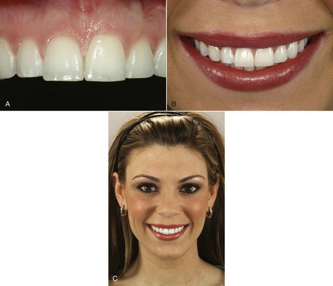
FIGURE 16-22 Same patient as Figures 16-20 and 16-21. A, The desired contact placement, embrasures, and connector length were successfully attained. B, The final close-up smile and (C) the final full-face smile. The comparison between Figures 16-20, A, and 16-22, C, demonstrates the effect of improving tooth display and contours.
For a patient with malformed or damaged teeth, the orthodontist needs to interact with a restorative dentist, often both during and at the conclusion of active orthodontic treatment (Figure 16-23). Temporary restorations so that all teeth are approximately the correct size make orthodontic finishing much easier. Modern restorative procedures, especially the use of laminated veneers, can make a significant difference in the quality of the final result. The orthodontic–restorative interaction is discussed in more detail in Chapter 18.
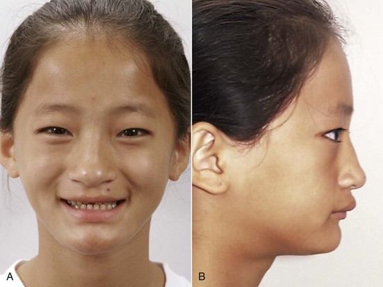
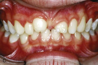
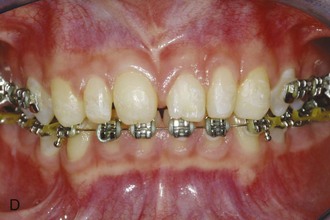
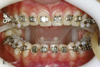
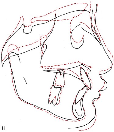
FIGURE 16-23 Pretreatment smile (A), profile view (B), and intraoral view (C) of an 11-year-old girl with malformed maxillary central incisors. Note the short face height, everted upper lip, and short crown heights. Treatment was deferred until age  , when she had become quite concerned about the “no teeth” appearance of her smile, and was judged to be beginning her adolescent growth spurt. It then was directed toward extrusion of posterior teeth to gain greater face height, using both cervical headgear and vertical elastics. D, At age 14, after 18 months of treatment, the maxillary brackets were removed so temporary laminates could be placed to improve the proportions of the incisors and increase incisor display. E, Then brackets were replaced at a more gingival level and treatment was continued. F, After another 9 months of treatment, the braces were removed at age 15. With the temporary laminates still in place, the smile arc was more flat than ideal. G, At age 18 permanent laminates were placed on the incisor teeth, with a further improvement in the appearance of the smile. H, Cephalometric superimposition from age
  to 15, showing the increase in face height and eruption of posterior and anterior teeth that occurred during orthodontic treatment. The increase in face height and balance created by the orthodontic treatment made it possible to provide excellent restorations for the malformed teeth, and the restorations were a critical element in obtaining the overall result.
These micro-esthetic finishing procedures are a simple way to enhance the orthodontic result in a way that patients readily perceive and appreciate.
References
1. Burstone, CJ, Koenig, HA. Creative wire bending—the force system from step and V bends. Am J Orthod Dentofac Orthop. 1988;93:59–67.
2. Gianelly, AA. Asymmetric space closure. Am J Orthod Dentofac Orthop. 1986;90:335–341.
3. Othman, S, Harradine, N. Tooth size discrepancies in an orthodontic population. Angle Orthod. 2007;77:668–674.
4. Kokich, VG, Kokich, VO. Interrelationship of orthodontics with periodontics and restorative dentistry. In: Nanda R, ed. Biomechanics and Esthetic Strategies in Clinical Orthodontics. Philadelphia: Elsevier/Saunders, 2005.
5. Fields, HW. Orthodontic-restorative treatment for relative mandibular anterior excess tooth size problems. Am J Orthod. 1981;79:176–183.
6. Isaacson, RJ, Rebellato, J. Two-couple orthodontic appliance systems: torquing arches. Semin Orthod. 1995;1:31–36.
7. Zachrisson, BU. Buccal uprighting of canines and premolars for improved smile esthetics and stability. World J Orthod. 2006;7:406–412.
8. Zachrisson, BU. Maxillary expansion: long-term stability and smile esthetics. Am J Orthod Dentofac Orthop. 2002;121:432–433. [abstracted from World J Orthod 2:266-272, 2001].
9. Steffen, JM, Haltom, FT. The five-cent tooth positioner. J Clin Orthod. 1987;21:528–529.
10. Feldon, PJ, Murray, PE, Burch, JG, et al. Diode laser debonding of ceramic brackets. Am J Orthod Dentofac Orthop. 2010;138:458–462.
11. Eliades, T, Gioka, C, Eliades, G, et al. Enamel surface roughness following debonding using two resin grinding methods. Eur J Orthod. 2004;26:333–338.
12. Edwards, JG. A long-term prospective evaluation of the circumferential supracrestal fiberotomy in alleviating orthodontic relapse. Am J Orthod Dentofac Orthop. 1988;93:380–387.
13. Spear, FM, Kokich, VG, Mathews, DP. Interdisciplinary management of anterior dental esthetics. J Am Dent Assoc. 2006;137:160–169.
14. Sarver, DM. Enameloplasty and esthetic finishing in orthodontics—Identification and treatment of microesthetic features in orthodontics. Part 1. J Esthet Restor Dent. 2011;23:296–302.
15. Sarver, DM. Enameloplasty and esthetic finishing in orthodontics—Differential diagnosis of incisor proclination—The importance of appropriate visualization and records. Part 2. J Esthet Restor Dent. 2011;23:303–313.