Technologies That Enable Mobility
MOBILITY NEEDS SERVED BY WHEELCHAIRS
Disorders Resulting in Mobility Impairments
Functional Limitations of Mobility
Mobility Issues Across the Life Span
EVALUATION FOR WHEELED MOBILITY
Evaluation of the Human Factors
CHARACTERISTICS AND CURRENT TECHNOLOGIES OF WHEELED MOBILITY SYSTEMS
Frames that Provide Variable Seat Height
Frames that Accommodate Growth
Control Interfaces for Powered Mobility Systems
Specialized Bases for Manual Wheelchairs
Wheelchairs for Use by Older Clients
Wheelchairs for Bariatric Clients
Specialized Bases for Electrically Powered Wheelchairs
Customizable Electrically Powered Wheelchairs
IMPLEMENTATION AND TRAINING FOR MANUAL AND POWERED MOBILITY
Maintenance and Repair of Personal Mobility Systems
On completing this chapter, you will be able to do the following:
1 Discuss needs underlying evaluation of the consumer for a mobility system
2 Describe the three categories of mobility systems on the basis of the need served by each
3 Describe the two primary structures of wheelchairs
4 Identify the major characteristics of manual wheelchairs
5 Identify the major types of power mobility systems and their characteristics
6 Understand the influence of the relationship between the center of gravity of the user and the center of mass of the wheelchair on the function of the wheelchair
7 Describe the implementation phase for personal mobility systems
Mobility is fundamental to each individual’s quality of life and it is necessary for functioning in each of the performance areas: self-care, work or school, and play or leisure. As described earlier for other activity outputs, limitations to functional mobility can be either augmented or replaced with assistive technologies. The activity output of ambulation can be augmented with low-tech aids such as canes, walkers, or crutches or replaced by wheeled mobility systems of various types. In addition to the functional gain of increased independence in mobility, such other goals as positive self-image, social interaction, and health maintenance are achieved. This chapter focuses on wheeled mobility systems to enhance an individual’s mobility, including manual and power wheelchairs. Our emphasis is on the total process of delivering these systems to those who need them, from initial need and goal setting, through assessment and recommendation, to implementation and training.
HISTORY OF THE WHEELCHAIR
The first wheeled vehicle was likely made more than 20,000 years ago by placing two logs under a sled. The first reference to a wheelchair in literature was in 1588 in mid Europe (Trujillo, circa 1960). Artists’ drawings in the early 1500s show persons with disabilities still being transported in litters and carts. The first wheelchairs were wooden with solid wood wheels. They were too cumbersome to be self-propelled. King Phillip V of Spain used a wheelchair in 1700. His device had wooden wheels with wooden spokes, a reclining back, and an adjustable leg rest. This design was used for more than 200 years.
Wheelchairs were not used much in the United States until the Civil War. At that time chairs similar to King Phillip’s were used. These wheelchairs had cane seats and backs and wooden wheels; however, by the end of the war they had metal rims on the wheels. In the late 1870s wire-spoked wheels came into use, probably as a technology transfer from the bicycle industry. This design dominated wheelchairs until the 1930s. In 1932 Mr. H. A. Everest, a mining engineer who had sustained a spinal cord injury in a mining accident, teamed up with Mr. H. C. Jennings, a mechanical engineer. They developed the first folding wheelchair by using an X-brace construction. This design was considered lightweight (less than 40 pounds) for the times and only measured 10 inches wide when folded, which allowed it to be placed behind a car seat. The collaboration between Everest and Jennings led to the formation of the E & J Wheelchair Company. This design, with some modifications in materials and accessories (e.g., removable armrests, reclining features) dominated the industry for quite some time.
After World War II, wheelchair sports started as a part of the rehabilitation program at Stoke Mandeville Hospital in the United Kingdom. The purpose was to provide exercise and a recreational outlet for the many individuals who had been injured during the war. The success of this program spread to other countries and eventually led to the first international wheelchair sporting competition, which was held in 1952. Athletes with disabilities competed for the first time in the same venues as Olympic athletes in 1960 (Cooper, 1998). The popularity of wheelchair sports has grown considerably since this time and has had a significant effect on wheelchair design and performance.
Advances in medicine and medical technology also followed World War II, leading to a significant increase in the numbers of individuals with paraplegia or quadriplegia surviving an accident or a disease who before that time would have died or lived a very short life. People with mobility impairments began to participate more actively in life roles and saw to it that improvements were made in mobility technology, which allowed them to maximize their participation in everyday life activities. As wheelchair users became more active and empowered, they started modifying their own chairs to suit their needs (Cooper, 1998). These needs led to the development in the late 1970s of lighter, more maneuverable wheelchairs that could be used in racing, basketball, tennis, and other sports. These needs also led to the development of the rigid or box frame style, which provided a better ride and was stronger. The advances made in sports and ultralight wheelchairs eventually became available in chairs for everyday use.
Power wheelchairs are a much more recent development. Although a patent was issued in 1940, these systems did not come into common use until 1957 (Hobson, 1990). The first models were standard folding wheelchairs with automobile motors and batteries added that functioned at a single speed. Gradually engineers began to develop new designs specifically intended for powered use. The revolution in electronics and computer technology also had an influence on power mobility systems. The use of solid state electronics for control systems increased reliability over previous electromechanical (relay) systems. Improvements in microcomputers allowed flexibility in control and provided the ability to alter the mobility system characteristics to match the users’ needs more closely. These advances have made it possible for individuals who have difficulty controlling a standard joystick to operate a power wheelchair.
Changes in wheelchair technology over the last century allow individuals with limitations in mobility to become more independent and to actively participate in society. Today many of these early inventions still are evident in current designs, but dramatic advances in materials, electronic controllers, and mechanical design have led to a proliferation of types, styles, and approaches to both manual and powered mobility. Changes in wheelchair technologies are expected to continue. Thus it is imperative that the assistive technology practitioner (ATP) remains current with new technologies as they become available and know how to define the user’s needs and skills so that a match can be made to the appropriate technology.
MOBILITY NEEDS SERVED BY WHEELCHAIRS
There has been a significant increase in the number of individuals using mobility systems; this change is related to three different trends. The population of most developing countries is aging with proportions of older individuals (65 years and older) expected to reach more than 20% of the population by 2030 in the United States (Bureau of the Census, 2004) and earlier in Canada (Belanger, Martel, and Caron-Malenfant, 2005). Age-related physical changes such as arthritis result in mobility impairments that require the use of mobility devices. The proportion of morbidly obese individuals is increasing in North America, which has resulted in the development of mobility devices that are specifically designed to support the increased size and weight of these individuals. Bariatric chairs are now available for these individuals whose mobility is impaired by obesity and related chronic diseases. Accessibility legislation in many countries has reduced physical and institutional barriers to the community participation of individuals with disabilities, with the result that more people are using mobility devices for instrumental activities of daily living (IADLs).
Data collected in the 2000 U.S. census indicate that 20.9 million U.S. families have at least one individual with a disability living in their households (Wang, 2005), and of these, 16.6% report a physical disability that results in a functional limitation. The Profile of Disability in Canada indicates that 13.7% of the Canadian population reports a mobility impairment (Cossette, 2002).
Kaye, Kang, and LePlante (2002) provide information on the number of Americans who use mobility devices. These data are derived from the 1994-1995 National Health Interview Survey on Disability. The survey indicated that 1.6 million Americans who live outside an institutional setting use a mobility device. The majority of these individuals (1.5 million) use a manual wheelchair (Kaye, Kang, and LePlante, 2002). Elderly individuals have the highest rate of mobility use, with 57.5% of manual wheelchair users and 69.7% of powered wheelchair uses reportedly 65 years of age or older (Kaye, Kang, and LePlante, 2002).
Disorders Resulting in Mobility Impairments
There are many causes of mobility impairment. Disorders that result in mobility impairment may be neurological, musculoskeletal, or cognitive. Not all individuals with a given diagnosis have a similar impairment in mobility. The onset of the disorder, whether it was acquired or congenital, also affects the individual’s mobility needs.
Kaye et al (2002) present the top 10 conditions in the United States that result in use of a wheelchair or scooter. Individuals who have sustained a cerebral vascular accident are the leading group of mobility device users (11.1%) (Kaye et al, 2002). Additional neurological disorders that may result in mobility impairment include cerebral palsy, Guillain-Barré syndrome, Huntington’s chorea, traumatic brain injury, muscular dystrophy, Parkinson’s disease, poliomyelitis, spinal cord injury, spina bifida, and multiple sclerosis. Symptoms commonly seen in these neurological disorders are muscle weakness or paralysis, sensory deficits, and abnormal muscle tone. All these disorders can lead to limitations with joint range of motion, postural control, and mobility. The individual may also have cognitive and behavioral problems as a result of the disorder.
Orthopedic and rheumatological conditions account for another large group of mobility device users. Some of the symptoms commonly seen in individuals with arthritis include painful, swollen, and stiff joints; muscle wasting around the affected joints; and, in later stages, joint contractures resulting in range-of-motion limitations. Other disorders that affect the musculoskeletal system and may result in mobility impairments include ankylosing spondylitis, osteogenesis imperfecta, osteoporosis, Paget’s disease, and scoliosis. Individuals with an amputation may also use a mobility device.
Diabetes, cardiorespiratory conditions, and obesity are final chronic conditions that may require the use of a mobility device. Frequently, fatigue or restrictions related to energy expenditure are the reasons for use of a mobility device with this population. Amputations resulting from complications from diabetes may also lead to the use of a mobility device.
Disorders that affect an individual’s cognitive functioning and ability to learn, such as Alzheimer’s disease and mental retardation, can also be the cause of mobility impairments. Although the onset of mental retardation is at birth, the onset of Alzheimer’s disease is later in life. Consequently, there are unique aspects to each of these disorders that need to be considered by the ATP; some of these are discussed in this section.
Functional Limitations of Mobility
Limitations to mobility can also be viewed as functional limitations of an individual rather than as conditions related to specific diagnoses (Warren, 1990). The degree of limitation in mobility varies across a broad scope, as shown in Box 12-1. At one end of the range are individuals who are considered marginal ambulators. At the opposite end of the range are those individuals who have severe mobility limitations and are dependent in manual mobility, with powered mobility being their only option for independence.
Warren (1990) describes marginal ambulators as able to move independently in their environment but functional only at a slow rate or for short distances. Persons who have marginal ambulating skills can benefit from part-time use of a powered mobility device such as a scooter, which allows them to walk inside the home using a walker or cane and use a powered device outside the home to augment ambulation. Next are individuals who are exclusive users of manual wheelchairs. Either they are dependent in the use of a manual wheelchair or they propel a manual wheelchair by one of three methods: (1) using both upper extremities, (2) using both lower extremities, or (3) using an upper and lower extremity on the same side of the body (e.g., a person who has had a stroke). There are also marginal manual wheelchair users, who are able to propel a wheelchair manually but have upper body weakness, respiratory problems, or postural asymmetry as a result of pushing that limits their ability to propel a manual chair for a prolonged time (Warren, 1990). Marginal manual wheelchair users may also include individuals who formerly used a manual wheelchair for their mobility needs and have sustained an overuse injury from propelling the chair. Propelling a wheelchair for any length of time depletes the energy of these individuals and compromises their productivity in other areas of life. Marginal manual wheelchair users can benefit from powered mobility on a full-time or part-time basis.
At the extreme end of the range are those individuals who have a severe mobility limitation; their only means of being independent in mobility is through the full-time use of a powered mobility system. These individuals typically have a manual wheelchair, propelled by a caregiver, as a backup chair. Individuals with severely limited motor control, who are physically unable to move around in their environment without equipment, are the ones traditionally considered for powered mobility and for whom the benefits are clear. With the provision of powered mobility, these individuals can independently participate in work, school, and recreational activities. The control interfaces (see Chapter 7) that are available today make it possible for someone with only one or two movements to operate a powered wheelchair; however, perceptual, cognitive, and behavioral impairments may prevent individuals from using a power wheelchair even if they have the necessary motor skills. Frequently, these individuals also use other devices such as an augmentative communication system or an adapted van, which requires that the integration of all these devices be considered at the time of selection of the most appropriate mobility device. All mobility device users will require a system to support their seating needs (see Chapter 6).
Mobility Issues Across the Life Span
Mobility needs differ across the life span, with children having much different mobility needs than adults. Although there are many life span issues to consider, we focus on two issues that warrant special attention: (1) powered mobility for young children and (2) mobility for older adults.
The use of powered mobility by young children is an area that has received a great deal of attention in the last decade. In the past, powered mobility was deemed inappropriate for young children for a number of reasons. These concerns were related to the ability of children to operate a power wheelchair safely, the initial cost of the wheelchair and the cost of replacing it as the child grows, and possible detrimental effects on physical development if the child depends on a powered system instead of his own locomotion (Kermoian, 1998). Recent studies have demonstrated that children as young as 18 to 24 months can safely operate powered vehicles (Magnuson, 1995; Trefler and Cook, 1986). Powered vehicles allow disabled children to experience movement and control and can facilitate their social, cognitive, perceptual, and functional development (Butler, 1997; Trefler, Kozole, and Snell, 1986).
Like other areas of assistive technology use, it is suggested that a child be given access to multiple modes of locomotion and be allowed to select the one that is most convenient and most efficient for the given activity (Butler, 1997). By augmenting a child’s self-locomotion with wheeled mobility devices, normal childhood development can be simulated. There are an increasing number of powered mobility devices available that can be used to augment a young child’s mobility. A transitional mobility device can provide the young child with the means for independent locomotion without the complexity and expense of a power wheelchair. Transitional mobility devices include motorized toy cars and powered standing frames. Frequently, parents who resist standard powered mobility devices for their child are more accepting of motorized toy cars that facilitate play with their peers (Deitz, 1998). Deitz (1998) discusses the many factors that should be considered in the design and evaluation of mobility devices that facilitate self-locomotion in young children.
At the opposite end of the life span is a population that also deserves special attention when it comes to designing and recommending assistive technologies for mobility impairment: the older adult. Older adults represent a large proportion of individuals who use mobility devices. As the number of people in this group increases, so will the people with mobility impairments. Wheelchair users over the age of 60 years tend to have limited mobility associated with the aging process, osteoarthritis, and cardiorespiratory disease and typically are occasional wheelchair users (Ham, Aldersea, and Porter, 1998).
Some needs that are specific to the older adult wheelchair user have been identified in the literature. The older adult wheelchair user often depends on another person to push the wheelchair. Therefore, a mobility device that can be used easily by an attendant is important (Ham, Aldersea, and Porter, 1998; Trefler et al, 1993). Comfort, safety, and security have been identified as important needs related to seating and mobility for residents of long-term care facilities (Lacoste et al, 1998, Mortenson et al, 2005; Mortenson et al, 2006). Safety and security were deemed important for the user of the wheelchair, as well as for the care provider. For instance, it is important that the care provider be able to transfer a person in and out of the wheelchair safely. Both the user and the care provider will be more inclined to use a wheelchair that is comfortable, safe, secure, and “attendant friendly.” Because the ultimate goal of wheeled mobility is to allow individuals to participate in their environment, taking these factors into consideration will ensure that the older adult with a mobility limitation is not prohibited from being a part of society.
Wheelchairs that target the bariatric client are a recent development in wheelchair design. Bariatrics is a term that describes the practice of medicine concerning individuals who are significantly overweight. It is derived from the Greek “baros” meaning weight and “iatrics” meaning medical treatment. In some situations, the client’s obesity is the cause of the mobility impairment. Obesity has become a major health problem in North America. The Centers for Disease Control and Prevention (CDC) (2006) report a growing trend in the prevalence of obesity (generally defined as a body mass index [BMI] of 30 or more). In 1995, the prevalence of obesity was less than 20% in all states. In 2000, 28% of states reported obesity prevalence of less than 20% and by 2005 this incidence had dropped to only four states. The 2005 figures further indicate that 17 states report a prevalence of obesity of equal to or greater than 25% and three a prevalence rate of equal to or greater than 30% (CDC, 2006). Diabetes is a serious chronic health condition that is associated with obesity. All these factors limit the individual’s ability to move independently in the environment. Typical wheelchairs have standard weight limits up to 300 pounds. Chairs for bariatric clients are capable of supporting weights up to 600 pounds and in some cases up to 1000 pounds. Examples of these chairs will be described later in this chapter. Clients who are morbidly obese present specific challenges when measuring for a wheelchair, as will be discussed later.
EVALUATION FOR WHEELED MOBILITY
The goal of wheeled mobility intervention is to support the user’s ability to move in the environment (i.e., the mobility output of the activity component of the human activity assistive technology [HAAT] model). Consistent with the HAAT model described in Chapter 2, the evaluation to determine the most appropriate wheeled mobility base starts with an assessment of the activities in which the individual wishes to engage while using mobility technology. Will the mobility device be used primarily to move from one place to another in the community or will the individual use it as the primary means of mobility and consequently perform most activities (e.g., ADLs, work and leisure occupations) while seated in the device? The ATP should determine which activities are important and necessary for the device user to complete as well as those in which he or she wishes to engage. Further, the level of assistance individuals require to complete these activities is also an important consideration. Will they complete these activities on their own, with the assistance of another person, or using other technology such as an augmentative communication system?
Evaluation of the Human Factors
Box 12-2 identifies the factors that should be considered when selecting a mobility base for a consumer. It is important to know what the person’s disability is so that its influence on the person’s level of functioning can be ascertained. It is important to know whether the disability is temporary or permanent and whether the person’s condition is expected to improve, progressively deteriorate, or remain stable. For example, an individual who has recently had a stroke may be expected to regain functional ambulation, but for the short term requires a system for mobility. In this situation the rental of a wheelchair would be warranted. On the other hand, an individual with amyotrophic lateral sclerosis is expected to lose functional abilities and requires a mobility system that will accommodate this deterioration in functional status. An individual with a complete spinal cord injury at the C6 level will not typically demonstrate significant changes in mobility after injury and requires a mobility system on a long-term basis.
The individual’s physical and sensory skills are evaluated for range of motion, strength, motor control, skin integrity, vision, and perception. This assessment also includes determining the user’s optimal control site and interface for propelling the wheelchair. All these factors are discussed in Chapters 4, 6, and 7. Information on the person’s weight and size is gathered to determine the size and capacity of the wheelchair. Measurements of the person’s leg length, thigh length, back height to base of scapula, back height to top of shoulder, and hip breadth are taken while the person is sitting. A very large person will need a bariatric wheelchair. Clients who are obese should be measured in sitting because adipose tissue spreads when they lie down, resulting in an inaccurate measurement (Daus, 2003). If the consumer is a child and is expected to grow, that expected change needs to be reflected in the decision making as well.
The person’s functional abilities are also evaluated. Two elements are important. The first is evaluation of different ADLs and instrumental ADLs. In addition to identifying in which occupations the individual wishes to engage, this evaluation will determine how he or she completes those activities. The second element involves evaluation of wheelchair skills. The Wheelchair Skills Test (Kirby et al, 2002, 2004) is a well-developed, standardized measure of various wheelchair skills. This test assesses the individual’s ability to perform basic wheelchair skills such as removal of an armrest and application of the brakes to more complex, advanced skills such as performing a wheelie to negotiate a curb. This test is one of the few that has had extensive research in all phases of its development. In addition to the evaluation, a training program has also been developed and evaluated. Information about this test and the training program are available at www.wheelchairskillsprogram.ca.
Environmental Factors
The ATP needs to explore the physical contexts in which the mobility device will be used. Will the device be used both indoors and outdoors? How accessible are these environments? Width of doorways, floor surfaces, bathroom layout, and access to the structure (e.g., ramp, stairs) all need to be considered. On what type of surfaces will the consumer travel when using the device outdoors? Does the user expect or need to transport the device between different locations such as home, school, or work? How will the user and the mobility device travel (e.g., will he or she use a private vehicle or public transportation)? Does the user access other modes of transportation such as trains or airplanes?
Just as the climate was a factor in the recommendation concerning a seating system, it also influences the recommendation of a mobility device. A different recommendation for a device may be made if the consumer lives in a climate where snow is a typical part of winter and he or she expects to use the device outdoors versus a consumer who lives in a climate where snow and cold temperatures are not a routine expectation.
Social Context.
Family members, peers, and others in the social environment can influence the choice of a mobility device. Peers with experience with various mobility devices can be a great source of information and can share their knowledge of what works and what does not. Conversely, peers and families may exert pressure in the choice of a manual versus a power wheelchair. The individual may prefer to use a powered chair because it allows him or her to conserve energy for other occupations but may be viewed as lazy by others if this technology is chosen. The willingness or ability of decision makers in the school, workplace, and other community environments to accommodate various types of mobility devices also needs to be considered.
Institutional Context.
Institutional regulations and policies influence the recommendation of a mobility device. The ATP needs to be aware of the criteria for funding these devices in his or her jurisdiction. The ATP needs to consider the client’s future needs and the implications that a current recommendation will have on the ability to access an appropriate mobility device in the future. For example, some funding programs have a specified time during which a new system will not be funded. Further, some stipulate that if a person receives one type of mobility device, a second one will not be funded or not funded for a period of years (e.g., 5-year life of the system). Funding agencies, in particular those funded with public money, produce criteria that identify functional abilities of the individual and stability of the medical condition that determine whether funding will be available to assist with the purchase of a device. Each ATP is responsible for knowing the regulations and policies regarding access to mobility devices in his or her jurisdiction.
CHARACTERISTICS AND CURRENT TECHNOLOGIES OF WHEELED MOBILITY SYSTEMS
This section discusses the major characteristics of manual and powered mobility systems. Table 12-1 lists the major manufacturers of personal mobility systems. Modern mobility systems are more flexible and more capable of being adapted to a variety of functional tasks. These adaptations may include height adjustment, recline, axle position adjustment, and combinations of all these. The selection of a wheelchair is based on the evaluation discussed in the previous section and is a process of matching characteristics to the consumer’s needs and skills. This section discusses the characteristics of mobility systems, starting with the wheelchair’s two basic structures: a supporting structure and a propelling structure. To meet the varied needs of individuals with mobility impairments, there are three broad categories of wheeled mobility systems: dependent mobility, independent manual mobility, and independent powered mobility.
TABLE 12-1
Major Wheelchair Manufacturers
| Manufacturer | Type of Wheelchairs | Web Address |
| Alber (in the United States) | Stair-climbing wheelchair; add-on power unit | www.ulrich-alber.de/en/index.php |
| Frank Mobility Systems, Inc. | ||
| 888-426-8581 | ||
| Altimate Medical, Inc. 800-342-8968 | Standing systems | www.easystand.com |
| Amigo Mobility International, Inc. | Scooters | www.myamigo.com |
| 800-692-6446 | ||
| Bruno Independent Living Aids | Adult and pediatric scooters, sedan and van wheelchair lifts | www.bruno.com |
| 800-882-8183 | ||
| Columbia Medical | Dependent mobility bases | www.columbiamedical.com |
| 800-454-6612 | ||
| Convaid, Inc | Dependent mobility bases, transport chairs | www.convaid.com |
| ConvaQuip | Bariatric wheelchairs | www.convaquip.com |
| Etac (in the United States) | Independent manual wheelchairs for children and adults | www.etac.com |
| Balder USA, Inc. 888-422-5337 | ||
| Frank Mobility Systems, Inc. 888-426-8581 | Stair-climbing wheelchair, add-on power unit | http://www.frankmobility.com |
| Freedom Designs 800-554-8044 | Pediatric wheelchairs, tilt-in space wheelchairs | www.freedomdesigns.com |
| Gendron, Inc 800-537-2521 | Bariatric manual and power wheelchairs | www.gendroninc.com |
| Graham-Field Health products 888-426-5881 | Dependent and independent manual, sports wheelchairs, adult and pediatric chairs, tilt chairs | http://www.grahamfield.com/Channels/Home.aspx?MenuID=1 |
| Innovative Products, Inc. 800-950-5185 | Pediatric powered mobility | www.mobility4kids.com |
| Invacare 800-333-6900 | Manual, power, and sports wheelchairs | www.invacare.com |
| Levo USA, Inc. 888-538-6872 | Manual and powered stand-up wheelchairs for adults and children | www.levo.ch |
| Life Stand (Vivre-Debout) | Manual and powered stand-up wheelchairs for adults and children | www.lifestand-usa.com |
| (in the United States) | ||
| Frank Mobility Systems, Inc. | ||
| 888-426-8581 | ||
| Motion Concepts 888-433-6818 | Specialty powered wheelchairs | www.motionconcepts.com |
| Mulholland Positioning Systems, Inc. | A variety of standing systems, pediatric wheeled bases, and tilt bases | www.mulhollandinc.com |
| 800-543-4769 | ||
| Otto Bock 800-328-4058 | Pediatric seating and positioning, adult positioning, manual and power wheelchairs | www.ottobockus.com |
| PDG 888-858-4422 | Wheelchairs for individuals with special needs, such as bariatric chairs; high agitation and manual tilt wheelchairs | www.pdgmobility.com |
| Permobil, Inc. 800-736-0925 | Stand-up power wheelchairs; power wheelchair with elevating seat; sports wheelchairs; lightweight manual wheelchairs | www.permobil.com |
| Pride Mobility Products Corp. | Manual and electrically powered wheelchairs, scooters | www.pridemobility.com |
| United States 800-800-8586 | ||
| Canada 888-570-1113 | ||
| Snug Seat 800-336-7684 | Specialty bases for children and adults, car seats, dependent and independent mobility bases, pediatric wheelchairs | www.snugseat.com |
| Sunrise Medical 800-333-4000 | Dependent and independent manual bases, sports wheelchairs, lightweight manual wheelchairs, power wheelchairs, add-on power unit; adult and pediatric wheelchairs, tilt wheelchairs and scooters | www.sunrisemedical.com |
| TiLite 800-545-2266 | Adult and pediatric titanium wheelchairs; manual wheelchair; sports wheelchair | www.tilite.com |
| www.titaniumsports.com |
Dependent mobility systems, which are propelled by an attendant, include strollers and transport chairs. A dependent mobility system is chosen when (1) the individual is not at all capable of independently propelling a wheelchair (likely because of cognitive, perceptual, or behavioral deficits) or (2) a secondary system is needed that is lightweight and easily transported.
An independent manual mobility system is for those individuals who have the ability to propel a wheelchair manually. These bases have two large wheels in the back and two smaller front wheels that allow the user to propel independently.
Independent powered mobility systems are required when the user has difficulty propelling a manual wheelchair. These are electrically powered wheelchairs that are driven by the user. Within each of these categories there are many commercial options available to meet the needs of the individual user. This section discusses the characteristics of mobility systems, starting with the wheelchair’s two basic structures: a supporting structure and a propelling structure. Figure 12-1 shows the anatomy of a manual wheelchair.
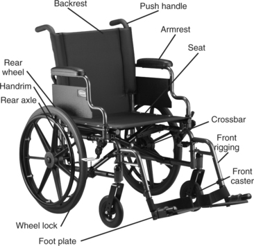
Figure 12-1 Manual wheelchair showing the major parts of the supporting and propelling structures. (Courtesy Invacare Canada.)
Supporting Structure
The supporting structure of the wheelchair consists of the frame and attachments to it. Specialized seating and positioning (see Chapter 6) are often considered part of the supporting structure. Accessories to the frame (e.g., armrests, footrests) are also a part of the supporting structure. In some wheelchairs these accessories are manufactured as part of the frame. Some supporting structures are unique in that they are adjustable to allow for changes in the orientation of the user in space, which includes systems that tilt, those that change the seat-to-back angle, and those that provide support in a standing position.
Frame Types.
Three underlying factors will be discussed before different classifications of manual wheelchairs are described: type of frame (rigid or folding), adjustability of the position of the axle of the rear wheel, and material used to construct the wheelchair frame.
Frames may be either folding or rigid (Figure 12-2), and there are three common frame styles (Cooper, 1998). Rigid frames are available in a box, cantilever, and T or I frame style (Figure 12-3). Typically the box frame construction has a rectangular shape that provides a strong and durable base to which the seat and wheels are attached. Lighter weight designs are accomplished by replacing the box with a single bar extending between the wheels, forming a cantilever structure. Upright tubes from this main support are used to attach the seat and back. The footrests are extensions of the seat rails. As shown in Figure 12-3, the T construction uses a bar similar to the cantilever design but has a single bar attached to the center of the cantilever that connects to a single front caster. This configuration forms a T shape under the seat. If two front casters are used, then the T becomes an I shape. For transportation, the wheels on all these chairs are removed, and in some cases the back folds down. The choice between rigid or box frame and folding frame styles involves a number of elements including the consumer’s needs, functional ability, method of transfer, and level of activity (Cooper, 1998).
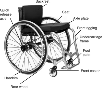
Figure 12-2 Rigid frame wheelchair showing the major parts of the supporting and propelling structures. (Courtesy Invacare Canada.)
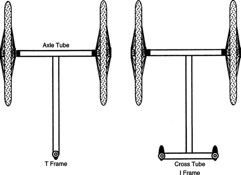
Figure 12-3 T and I frame styles. (From Cooper RA: Wheelchair selection and configuration, New York, 1998, Demos Medical Publishing.)
Demos Medical PublishingThe position of the axle of the drive wheel relative to the user’s center of gravity affects the stability and maneuverability of the wheelchair. Figure 12-4 displays this relationship. The center of mass of an empty wheelchair is located under the seat, in front of the drive wheels (Engstrom, 2002). When the user is seated in the wheelchair, the center of mass moves above the seat and forward and backward, depending on the seated position of the individual and the drive wheels. When the center of mass is forward of the axis of the drive wheels, more weight is placed on the castors, making it more difficult to lift them (Engstrom, 2002). The chair is more stable but less maneuverable in this configuration. As the center of mass moves backward, closer to the axis of the drive wheel or even slightly behind it, stability decreases and maneuverability increases. Understanding this relationship is important when setting up the chair. An active user will want a configuration that is easily maneuverable and allows him or her to perform a wheelie (i.e., lift the castors up, to clear curbs and other barriers). A less confident wheelchair user will be most comfortable with a chair that does not tip backward easily, allowing him or her to feel secure in the chair.
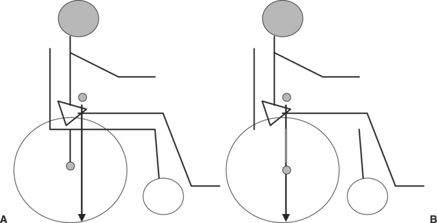
Figure 12-4 Relationship of the center of mass of the user to the axle of the wheel affects the mobility and stability of the chair. A, When the user is seated with his center of mass ahead of the axle of the wheelchair, the chair is more stable. B, When the user is seated with his center of mass directly above the axle of the wheelchair, the chair is more mobile
Another fairly recent advancement in the wheelchair industry is the material used to form the chair frame. Much of the advancement in materials comes from the cycling industry. Wheelchair frames are made from many different materials, including steel, aluminum, steel/aluminum alloy, titanium, and carbon fiber composites. These materials vary in their weight, strength, cost, how they conduct vibration, method of attaching components together, and how they are formed. Understanding the benefits of each material in combination with the user’s needs will help determine whether the functional benefit is worth the cost of the higher end materials.
Wheelchairs are classified according to a number of parameters, including weight, adjustability, and available options. Standard wheelchairs are generally useful for very short-term use such as rentals at an airport or shopping mall (Schmeler and Bunning, 1999). They are folding chairs, with very limited adjustment; in particular the axle of the rear wheel is fixed. Features such as footrests and armrests may be fixed or detachable. There is limited choice of seat width and depth. They are the heaviest of the manual wheelchairs and therefore are not useful for long-term use because they require a great deal of energy to propel on a regular basis.
Lightweight chairs (Schmeler and Bunning, 1999) weigh less than the standard chair, as their name would suggest. Otherwise, they tend to have similar features. These chairs offer more flexibility in choice of seat width and adjustment of back height. Both the standard and lightweight chairs are available with a lower seat-to-floor height that allows the user to propel the chair with the feet.
An ultralightweight wheelchair is substantially lighter than the standard chair. Schmeler and Bunning (1999) suggest that the chairs in the standard and lightweight categories are not suitable for use over the long term. The ultralightweight chair is one they consider useful for an individual who uses a manual wheelchair as the primary means of mobility. It retains the folding frame and is available with a lower seat-to-floor height for individuals who propel with their feet. The axle of the rear wheel is adjustable relative to the center of gravity of the user.
Rigid ultralight wheelchairs (Schmeler and Bunning, 1999) are a huge growth area for the wheelchair industry. The primary difference between these and the previous categories is the rigid frame. These chairs have quick release rear wheels and the back of most folds down to facilitate transfer and storage of the chair in a vehicle. The axle of the rear wheel of these chairs can be adjusted relative to the center of gravity of the user.
Accessories.
Armrests on conventional wheelchairs may be manufactured as a fixed part of the frame, flip back out of the way, or be completely removable. Nonremovable armrests decrease the width of the wheelchair slightly and do not get lost because they cannot be removed. In general it is advantageous to have armrests that flip back or are removable to facilitate transfers and other activities. Two lengths of armrests are available. Desk-length armrests are shorter in the front to allow the consumer to move close to a desk or table. Full-length armrests, which provide more support, extend to the front of the seat rails. Armrests may be fixed or adjustable in height. Armrests that are height adjustable can be moved up or down to accommodate the length of the user’s trunk and provide the proper amount of support for the arms. A clothing guard on the armrests prevents clothing and body parts from rubbing against the wheels. Leg rests and footplates support the legs and feet. Taken together, these two components are often called the front rigging of the wheelchair. Angle options are often available for the leg rests with either 90- or 70-degree hangers. These options increase the comfort of the user by accommodating the preferred knee flexion angle, but they can also add to the turning radius, which may be a factor for mobility in some environments. Leg rests may be fixed (built into the frame) or removable (swing away). Styles that swing away make it easier to transfer in and out of the wheelchair. Footplates are attached to the leg rests and are available as a single plate to support both feet or as two separate units, with individual height adjustment. The height of the footplate should support the desired position of the lower extremities. The angle of the footplate can also be adjusted to accommodate ankle flexion or extension. Heel loops can be attached to the back of the footplate to prevent the foot from sliding backward (see Figure 12-1). Wheel locks are the devices that prevent the wheels from moving, during transfers and other stationary activities. They are available in a number of configurations such as push or pull to lock, with lever extensions for individuals with limited reach, under the seat mounts, hill holders, and attendant controlled. Figure 12-5 shows some of the various wheel lock styles. When determining the type of wheel lock for the chair, consider how the user transfers in and out of the chair, his or her ability to access the wheel lock, the most reliable method available to manipulate the wheel lock, and the ability of the user or caregiver to maintain this component. As with the brakes of a motor vehicle, proper maintenance of the wheel locks is an important safety consideration.
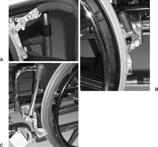
Figure 12-5 A, Example of a push-to-lock wheel lock. B and C, Examples of pull-to-lock. C, A wheel lock with an extended handle.
Antitip devices are small wheels attached to a rod and mounted at the back of the chair. These devices prevent the chair from tipping backward. When the drive wheels are located forward on the chair, antitip devices are recommended, particularly when the individual cannot safely perform a wheelie. Because these devices limit backward tipping of the chair, they can interfere with travel over some obstacles such as curbs. Antitip devices can be removed or rotated so they do not interfere with such travel when an attendant is pushing the chair. However, they must be returned to their original position when the user resumes propelling the chair (Engstrom, 2002).
Push handles are another option on a manual chair. These are the handles used by an attendant or caregiver to maneuver the chair. Some of these are height adjustable to accommodate the different heights of individuals who push the chair. Extended handles are available for pediatric chairs to avoid low back strain for the individual pushing the chair. Push handles have different shapes and are of different materials to assist with grip and handling in difficult situations such as inclement weather or traveling up or down a hill.
The upholstery of most wheelchairs that are intended for regular long-term use is designed to be used with a seating system. The option exists for most chairs to remove the upholstery completely and replace with a back or seat that is attached directly to the frame of the chair. Generally, only those chairs that are for occasional use come with a hammock style upholstery attached to the frame.
Frames for Recline and Tilt.
Tilt and recline features are available on both manual frames and power bases. Figure 12-6, A and B, shows examples of these systems. These features recognize that sitting is not a static activity and that we need to provide the opportunity to change position for individuals who cannot do so independently. Tilt refers to the ability to rotating a specific seating position around a fixed axis, changing the orientation in space. Recline refers changing the seat to back angle, resulting in a seat to back angle greater than 90 degrees (Lange, 2000). The seat-to-back angle typically ranges from upright to nearly horizontal. Tilt and recline have some common benefits to the user. Both provide a change of position and improved circulation, thus bringing pressure relief and greater comfort (Lange, 2000; Smith, 2004; Wilson and Miller Polgar, 2005). They have the potential to improve head and postural control, providing an improved functional position and influence muscle tone (Engstrom, 2002, Kreutz, 1997; Lange, 2000, Smith, 2004). They have the potential to improve respiratory function, provide a better visual field, regulate blood pressure, ease transfers and allow rest during the day (Kreutz, 1997; Lange, 2000). Recline or tilt can be used to achieve a more typical spinal alignment, for example, to reduce a thoracic kyphosis (Engstrom, 2002).
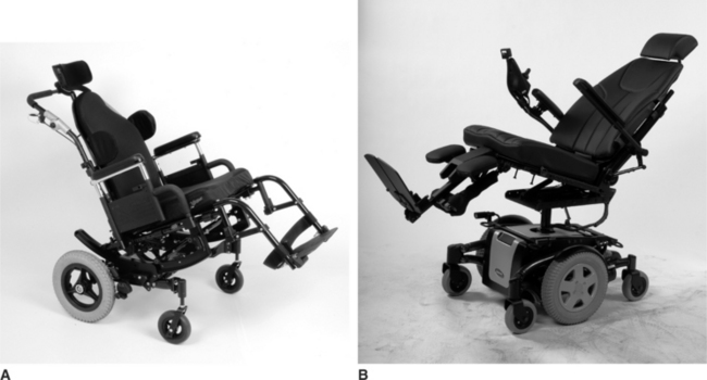
Figure 12-6 Tilt-and-recline wheelchair supporting structures. A, Supporting structure with tilt feature (Courtesy Sunrise Medical.) B, Supporting structure with recline feature (Courtesy Motion Concepts.)
Recline is also useful for individuals who become fatigued when sitting upright for a length of time. A chair with a recline feature allows rest without the need to transfer to bed. Recline also can accommodate cases in which more than 90 degrees of hip flexion is required, either because of structural limitations or when a hip flexion angle of greater than 90 degrees helps the user maintain spinal extension. Recline provides passive range of motion of the hips and knees (when elevating legrests are also provided). It can alleviate orthostatic hypotension (Kreutz, 1997; Lange, 2000) and improve bowel and bladder function. Recline may be preferred to tilt in a work or social environment because it is considered to be less obtrusive by the user (Lange, 2000). Recline does not raise the knees during the position change, which allows the user to work at a desk or table. When elevating legrests are included, there is a potential to reduce edema in and improve circulation to the lower extremities (Lange, 2000).
Recline is not a good option for some consumers. Opening the hip angle will cause excessive extensor tone in some individuals, particularly children with cerebral palsy or individuals who have sustained a head injury. Obviously, it is not useful when the user has limited hip extension range of motion. Individuals who use a custom contoured seating system should not use a recline system because of the shear forces that are inevitably present when changing the seat to back angle.
Shear is of concern when changing the seat-to-back angle. In Chapter 6 shear is defined as the friction that occurs when two surfaces slide across each other. Shear has the potential to tear skin, which can lead to a pressure ulcer. Most recline systems are designed to minimize shear, referred to as low-shear systems. These systems follow the user as the system reclines, resulting in a reduction of shear but not its elimination (Smith, 2004). Low-shear systems are available in both manual and power options.
Tilt systems are recommended when it is desirable to maintain the seating position for function or for control of other devices mounted to the wheelchair, such as augmentative and alternative communication devices (Lange, 2000). Because the whole seat pivots around an axis, shear is not of concern as it is with a recline system. In addition to rearward tilt, some systems also provide lateral tilt, which again maintains the seating position but tilts the user in the sagittal plane. The combination of anteroposterior and lateral tilt gives the user control to change position as he or she wishes.
Tilt systems do pose disadvantages that recline systems do not. Most systems increase the seat-to-floor height. Further, when the user is in the tilt position, the knees are raised, sometimes higher than the level of the head. The seat-to-floor height and position may interfere with the ability to work at a table or desk and poses a risk for injury if the user attempts to move into a tilt position while seated at a desk or table. As the seat tilts and the knees are raised, the lower extremity may be impinged between a desk and the system (Lange, 2000). Because tilt maintains the hip angle (typically 90 degrees), bladder constriction may occur, causing problems with fully emptying the bladder (Kreutz, 1997). Extreme degrees of tilt may cause the user to feel posturally insecure, which has the potential to increase muscle contraction, thus defeating the purpose of alleviating fatigue. Finally, tilt may interfere with the use of a tray: objects will slide off a tray when in tilt.
Center of mass shifts are a consideration when evaluating a wheelchair that incorporates a tilt-in-space option. The relationship of the center of mass of the seat to the center of mass of the base must be considered. The center of mass moves posteriorly as the seat tilts on some systems. This movement can cause rearward instability if the center of mass of the seat is shifted too far back with respect to the center of mass of the base. Most wheelchair designs compensate for this concern with mechanisms that maintain the center of mass of the seat over the center of mass of the base.
Consumers who use either a tilt-in-space or a recline system frequently also have other assistive technology whose use must be integrated with these positioning options, specifically, control of a power wheelchair with a head array, use of a ventilator, and use of an adapted van. Head array controls should be turned off when the user is in the tilt or recline position so that he or she can fully rest the head. When a ventilator is mounted on the wheelchair, care must be taken to ensure that the tilt or recline mechanism does not impinge on the unit and that the ventilator retains its proper position (Lange, 2004). Finally, evaluation of the user’s method of transportation must be considered when tilt and recline options are used. Tilt increases the seat to floor height, which may prevent the user from transferring into an adapted van. Both have the potential to increase the overall length of the system, which may limit the maneuverability of the user and the chair once in a van (Lange, 2000; Phillips, Fisher, and Miller Polgar, 2005). Integration of wheelchairs with adapted vans will be considered in Chapter 13 when transportation is discussed.
Frames for Standing.
We normally think of mobility in terms of wheelchairs; that is, the user is seated. There are, however, many advantages to placing an individual in a standing position (Eng, 2004; Mogul-Rotman and Fisher, 2002; Walter and Dunn, 1998). Among the positive effects of standing are physiological improvement in bladder and bowel function, alleviation of orthostatic hypotension, prevention of decubitus ulcers (see Chapter 6), reduction in muscle contractures and osteoporosis, and improved circulation. In addition, there are psychological benefits from being able to interact face to face with other people. Standing frames and standing wheelchairs are two different types of supporting structures that allow the individual to stand.
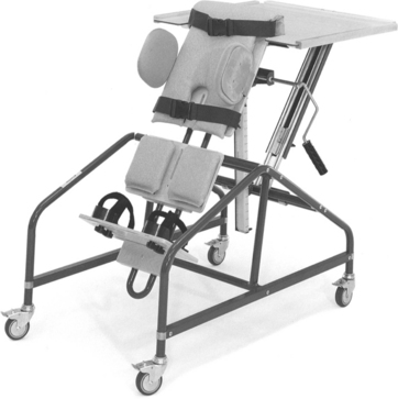
Standing frames are categorized as prone standers, supine standers, upright standers, and mobile standers (Mogul-Rotman and Fisher, 2002). Prone standers, such as the one shown in Figure 12-7, are the most common type. They provide support on the anterior side of the body. Weight bearing on the long bones and lower extremity joints is a major benefit. Often a lap tray is added to the stander, which serves two purposes. First, it provides a supporting surface for the upper extremities as the user leans on it. Second, it provides a work surface for activities such as writing, playing with toys, or using a communication device. Prone standers are generally tilted forward to use gravity for keeping the body upright in the stander. Some types have fixed angles and others are adjustable. Adjustment for growth is incorporated into some designs. This type of standing frame does not give the individual the option of moving into a seated position, as does the stand-up wheelchair, which is discussed below.
Supine standers are less common, and there are fewer options. This type of stander provides support for the posterior surfaces of the body. Because the user is leaned back, hand use is less functional. This type of stander is useful for persons who do not have good head control because the stander supports the head and neck. Upright standers provide for complete weight bearing on the lower extremities. People who have good upper body strength can use stationary models. Mobile versions are often sit-to-stand wheelchairs that allow changes in position from sitting to standing throughout the day. The change from sitting to standing and vice versa can be either powered or manual. When the user is in a vertical position, these units generally function like a prone stander.
Standing wheelchairs have both functional and social benefits. Many tasks of daily living, such as cooking, are simplified with the use of a standing wheelchair. Additionally, the use of a standing wheelchair may make it possible to avoid having to make modifications to a home or work setting. For example, a person cooking dinner while using a standing wheelchair is able to reach items in upper cabinets and reach the surface of cabinets and stoves without requiring modifications. Individuals who use a standing wheelchair report positive psychological benefits when they are at the same level as others (Eng, 2004).
Standing wheelchairs (Figure 12-8) are available in three basic configurations: manual driven with a manual lifting mechanism, manual driven with a power lifting mechanism, and power driven with a power lifting mechanism. Standing wheelchairs with manual lifting mechanisms consist of a hydraulic system that uses either a pump or a lever to raise the person to the standing position. With a powered system, the person activates a button to move into the upright position. When standing, the person is supported with padded bars at the knees and torso. Stability in the upright position is a concern with standing wheelchairs because movement into the standing position moves the client’s center of gravity forward in the chair, ahead of the center of mass of the base. For this reason not all standing wheelchairs are mobile while in the upright position. Those that are designed to be mobile in the standing positioning have a wider-than-normal base of support.

Although there are significant benefits to be gained from the use of standing frames and standing wheelchairs, their cost and size often limit usefulness, especially in a home environment. Selection must be based on a systematic evaluation, and the requirements of the individual consumer for a standing system are determined during the needs assessment. Fitting a consumer to a standing wheelchair poses some unique challenges in that the individual will be changing positions from sitting to standing; these dynamic positioning needs should be taken into consideration. Cooper (1998) offers some suggestions for fitting an individual for a standing wheelchair.
Frames That Provide Variable Seat Height.
Another available option on power wheelchair frames is a seat that can be lowered or raised. The person remains in a seated position, and when the mechanism is activated, the wheelchair seat raises and lowers within a given range. The mechanism to change the height of the wheelchair seat may be operated manually or with power. A seat that lowers near the floor is particularly useful for small children. Being at floor level allows the child to play on the floor and interact at a level with children his or her age. There are also benefits to raising the height of a seat. As with a standing wheelchair, a seat elevator is useful because it raises the person up and can make it easier for the individual to participate in certain self-care, work, and educational activities. As with standing wheelchairs and tilt in space and recline systems, the location of the center of mass has implications to safety. Some systems have a power lockout that prevents the chair from moving when the seat is raised to a certain height. Stability when traveling around corners may be compromised if the center of mass is too high relative to the footprint of the chair.
Frames That Accommodate Growth.
A major requirement of the supporting structure of the wheelchairs for children is that they accommodate growth. Two approaches are commonly used. The first of these is to design the supporting structure so that it can be adjusted directly. Kits are provided in the second option that allows replacement of various tubes on the frame increasing seat width and length, seat-to-floor height, and other important components.
Access to the drive wheels is another consideration when pediatric chairs are recommended. One strategy to improve this access is to set the drive wheels in slight camber. A second approach, for very young children, is to reverse the configuration of the drive wheels, placing them at the front of the chair with the casters at the back. Stability of the chair, rearward, must be carefully assessed with this configuration.
Push handles are a final consideration for a pediatric frame. Extended handles are available so that the caregiver does not need to lean or bend forward to grasp the push handles. This configuration greatly reduces the load placed on the caregiver’s lower back by allowing an upright position during this activity.
Propelling Structure: Manual
For manual or body-powered wheelchairs, the propelling structure consists of two main parts: (1) wheels (including tires and casters) and (2) an interface that the consumer uses to move the wheelchair (Ragnarsson, 1990). Each of these components is discussed in this section.
Tires.
There are three main types of wheelchair tires: solid, semipneumatic, and pneumatic (Robson, 2005). Solid tires require less maintenance of all types but are the least versatile. They generally perform well on smooth indoor surfaces but are less efficient when used on carpeted surfaces or other rough, uneven terrain. Solid tires typically have a smooth surface.
Pneumatic tires may have an inner tube or a flat free insert. Although they are useful over more varied terrain than solid tires, they require maintenance to maintain proper tire pressure and can be punctured, resulting in a flat. Sawatsky, Denison, and Kim (2005) found that rolling resistance and energy expenditure were significantly decreased when tires were inflated to 50% of their recommended pressure. They report clinical evidence that wheelchair tires are commonly found to be inflated to only 25% of their recommended pressure. In addition to maintaining tire pressure, the user should inspect the tires regularly for any cracks or imperfections that may lead to a flat. These tires are available with different tread depths; deeper treads are useful on rough terrain but create more rolling resistance when used on smoother surfaces.
Wheels.
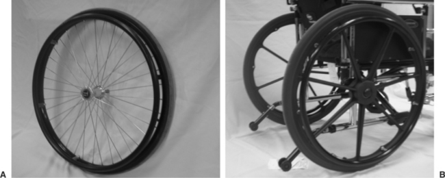
Rear wheels are of two basic types: composite or spoke, shown in Figure 12-9 (Robson, 2005). Composite wheels tend to be more economical than spoke wheels and require less maintenance. There is less risk of the user getting a hand caught in the wheel. These wheels tend to be more rigid than spoke wheels and thus may give a more uncomfortable ride (Robson, 2005). Spoke wheels do have more maintenance because it is more difficult to clean them and the spokes should be readjusted. These wheels tend to transmit less vibration from the surface to the user than do more rigid composite wheels (Robson, 2005). They are lighter in weight than composite wheels. High-performance wheels, such as the Spinergy wheel, are available for active users. These wheels use lightweight materials that provide better strength and greater shock absorption. Wheels range in size from 18 to 26 inches in diameter. Power wheelchairs typically have 18-inch wheels, and conventional manual types have 24-inch wheels.
Many wheelchairs allow adjustment of the location of the drive wheels forward or rearward on the chair. Figure 12-10 shows a mounting plate that allows adjustments of the position of the drive wheels. The location of the wheels relative to the center of gravity of the user affects the mobility and stability of the chair. When the axle of the wheel is located either directly under the user’s center of gravity or anterior to it, the result is a more maneuverable, responsive chair, one that is desired by the active user. More novice wheelchair users or those with less control will feel most comfortable with the axis of the wheel located behind the center of gravity, resulting in a more stable chair (Engstrom, 2002). A quick-release feature (see Figure 12-9) makes it possible to remove the wheel easily for transportation.
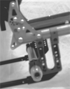
Figure 12-10 Axle plate of manual wheelchair that allows adjustability of the position of the rear wheels.
Wheel camber affects the responsiveness of the chair. Camber refers to the degree to which the wheel is mounted off vertical, usually 1 to 4 degrees. Camber tips the wheel so the top is closer to the user’s body. When the wheels are set this way, the wheelchair becomes more stable and propulsion is more efficient. There is greater access to the wheels. Camber increases the overall width of the chair and lowers the rear seat to floor height (Robson, 2005). Wheel alignment also affects the ease with which the chair can be propelled. Alignment refers to the degree to which the two wheels are parallel to each other. If they are not parallel and at equal distance from each other, there is greater rolling resistance for the wheelchair.
Casters.
The front wheels on wheelchairs are referred to as casters. They range in diameter from 2¾ to 8¼ inches (Fields, 1992). Larger casters give a smoother ride but are less responsive and can interfere with foot placement (Robson, 2005). Smaller casters are more responsive, contribute to more efficient propulsion, and allow more flexibility in position of the feet, but these benefits are compromised by a rougher ride (Engstrom, 2002; Robson, 2005). Solid semipneumatic casters are available. The relationship of the user’s center of gravity to the chair’s center of mass is important here. If the user is seated too far forward in the chair, excess weight is placed on the casters (i.e., front loading the casters), making it more difficult to propel because the force required to overcome inertia is greater (Engstrom, 2002). This situation may also result in loss of forward stability.
Shimmy is one of the major problems with casters (Fields, 1992). This term refers to the rapid vibration that is often felt when pushing a shopping cart. Smaller casters tend to have less shimmy than larger ones, but larger casters offer a smoother ride and are less likely to be caught on uneven surfaces. The major factors resulting in shimmy are the position of the caster fork and stem, the shape of the wheel, and the tension in the caster axle and swivel mechanism where they attach to the frame. Caster float occurs when one of the casters does not touch the floor when the wheelchair is on level ground (Cooper, 1998), which can result in reduced stability and performance. Excessive wear on one caster or unequal camber in the rear wheels will bring about caster float. Replacing the caster, adjusting the rear wheel camber, or lowering the caster that floats with a spacer can eliminate the problem (Cooper, 1998).
Caster placement affects the performance of the chair. Trailing casters are located with the caster behind the front vertical tube of the chair. Casters in this position reduce the overall length of the chair and improve the chair’s responsiveness but result in less forward stability of the chair. Leading casters are located ahead of the front vertical tube. Casters in this position increase forward stability and are less sensitive to front loading (as described previously). They do contribute to a longer wheelbase and are less responsive (Robson, 2005). Like other features on a chair, it is clear that the needs of the consumer in the various activities, for which he or she will use a wheelchair, need to be matched with the performance features of the casters. Similarly, maintenance is required to ensure that the casters are properly aligned and loaded.
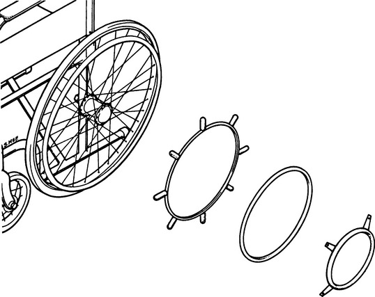
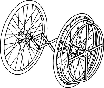
Hand Rims.
The human/technology interface for a manual wheelchair is most commonly a ring attached to the wheel, called a hand rim. Hand rims are made from a variety of materials, including titanium, aluminum, and stainless steel. They may have a vinyl coating. Knobs or extensions can be added for individuals who have difficulty gripping hand rims (Figure 12-11). Ergonomically designed hand rims use a material that spans the space between the wheel rim and the hand rim, thus allowing a natural fit with the user’s palm. If an individual has the use of only one arm and hand, two hand rims are put on the intact side and a linkage is attached between the inner hand rim and the opposite wheel, as shown in Figure 12-12 (Wilson and McFarland, 1990). By grasping both hand rims, the user can move forward. Turning is possible using one hand rim at a time.
Propelling Structure: Powered
The propelling structure of power wheelchairs has more variability than do manual systems. The major components are a wheeled mobility base with a power drive to the wheels, a control interface that the consumer uses to direct the movement of the wheelchair, an electronic controller, and powered accessories (e.g., recline, tilt). This section discusses current approaches.
Drive Wheels.
Electrically powered wheelchairs have undergone a tremendous change in the last decade. The development of microprocessing capabilities enables developers of powered mobility technology to include a wide range of functions in these devices. One of the most significant developments is the change in the location of the drive wheels. Power is delivered to one pair of wheels in mobility technology with the additional sets of wheels providing stability. Direct drive systems also often provide dynamic or active braking of the wheelchair by providing a voltage that stops the motor. This action offers more control than the common situation of letting the chair coast to a stop after the voltage is turned off to the motor. Most motors used are direct current types in which the speed is proportional to the voltage applied and the torque is proportional to the applied current. Cooper (1998) describes in detail the engineering considerations in wheelchair drive systems.
Electrically powered wheelchairs are generally classified as rear-, mid-, or front-wheel drive, depending on the location of the wheels that propel the chair. Rear- and mid-wheel drive chairs are the most common. In addition to castors, antitipping devices may also be present on a power chair. Figure 12-13 shows a typical mid-wheel drive electrically powered wheelchair, with the housing for the motor and batteries located underneath the seat.
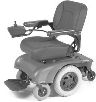
Figure 12-13 Electrically powered wheelchair with mid-wheel drive system. (Courtesy Sunrise Medical.)
Recently, Denison and Gayton (2002) proposed a different classification on the basis of the relationship of the drive wheel to the center of gravity of the user and the ratio of weight on the drive wheels to that on the castors. The drive wheels of a rear-wheel drive chair are located behind the center of gravity of the user. These are well behind the center of gravity in a low-ratio rear-wheel drive. The front wheels are castors and antitipping wheels may or may not be present. The drive wheels of a high-ratio rear-wheel drive are closer to the user’s center of gravity. In addition to front castors, antitipping wheels are located behind the drive wheels. The drive wheels of a mid-wheel drive chair are located directly under the user’s center of gravity. Castors are located both in front of and behind the drive wheels. These castors are intended to be in contact with the surface when the chair is in motion. The drive wheels of a front-wheel drive chair are located ahead of the user’s center of gravity, with the high-ratio front-wheel drive wheels being closer to the center of gravity than with the low ratio. The location of the drive wheels affects the performance of the chair, making it an important consideration when recommending a chair to a client.
Evaluation of the client’s physical and cognitive abilities and examination of his or her mobility needs are important steps in determining which type of powered wheelchair is most suited to the client’s needs and lifestyle. There is limited literature that evaluates the function of powered wheelchairs to assist the client and clinician in making a power mobility decision. Because the purchase of a powered wheelchair is a significant financial investment, a trial period of use of a potential chair is necessary. Rentschler et al from the Rehabilitation Engineering Research Center on Wheeled Mobility at the University of Pittsburgh used the American National Standards Institute (ANSI)/Rehabilitation Engineering Society of North America (RESNA) standards to evaluate five power chairs that were commonly recommended for clients in the Veterans Affairs health care system (Rentschler et al, 2004). They examined two rear-wheel drive chairs, two mid-wheel drive chairs, and one front-wheel drive chair. Outcome measures included static and dynamic stability, braking distance, energy consumption (i.e., range of a single battery charge under standard conditions), static, impact and fatigue strength, and performance under different climatic conditions. Stability tests were conducted under two conditions: chair configured in most stable manner and chair configured in least stable manner. Their results did not point conclusively to the benefits of one chair over another but did give a good initial foundation with which to compare a chair’s performance with the consumer’s needs.
Control Interfaces for Powered Mobility Systems.
There are a number of ways in which a power wheelchair can be controlled. Two control distinctions need to be made first before the various technologies are discussed: proportional versus nonproportional control. Proportional control with 360-degree directionality means that the chair moves in whichever direction the joystick is displaced, and the greater the displacement, the faster the chair moves (Lange, 2005). The joystick controls fewer degrees of movement with nonproportional control and, regardless of the displacement, the chair travels at a preselected speed. If the user wishes to change direction, he or she must release the joystick in one direction and activate it in the direction of the change (Lange, 2005).
Many options exist that provide access to power wheelchair controls. The ATP’s assessment includes the determination of movements that the client is able to make reliably. A similar process can be used to determine the most appropriate method of access, as was described in Chapter 7 regarding computer and augmentative and alternative communication access. An important difference between assessment for computer access and powered wheelchair control is that the ATP needs to determine that the movement used to control the power wheelchair is safe and reliable (i.e., the user must be able to initiate or cease a movement as required because he or she is controlling a moving vehicle).
Many of the types of switches that are described in Chapter 7 are also useful for powered mobility control. These switches can be mechanical or electronic (Lange, 2005). Mechanical switches must be physically activated to initiate a control command. For example, they must be moved, depressed, touched, or released. Electronic switches do not require physical contact from the user. Proximity switches activate when the user is close to the switch, but not necessarily touching it. Fiberoptic switches emit an invisible beam that initiates an action when interrupted (Lange, 2005).
The most common method of control of a power wheelchair is direct selection through the use of a four-direction joystick. Typically, a joystick can be positioned on either side of the chair or in midline to be controlled with the hand or forearm. It can also be fixed or mounted on a swing-away plate that facilitates transfers. It can be positioned to be used with the, chin, foot, leg, or head. When a chin joystick is used, an additional switch (often activated by a shoulder shrug) can be used to control a powered arm that moves the joystick into position for use and swings it out of the way for eating, talking, or mouthstick use.
Most joysticks have a ball on top. However, many different types of tops are available for users with different grasping abilities (Lange, 2005). For example, a U-shaped cuff that supports the person’s hand on the sides may enhance control of the joystick. Other variations include smaller or larger balls, a T-bar, and an extended joystick.
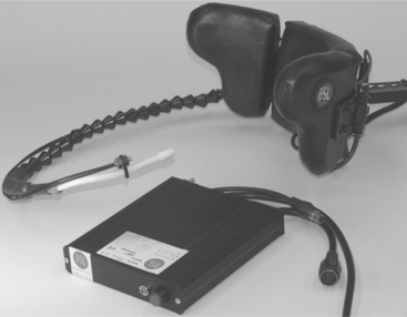
Sip-and-puff switches are a common control interface for individuals with a high spinal cord lesion. A small tube is placed in close proximity to the person’s mouth. The user controls the switch with either a puff (blowing air out of the mouth) or a sip (sucking air into the mouth). A hard puff causes the chair to move forward while a hard sip causes it to move in reverse. A soft puff turns the chair right; a soft sip turns it left. The forward direction is latched (i.e., once the user activates forward movement, the chair will continue to travel in that direction until reverse is activated). Good oral motor control is required to use a sip-and-puff system. Figure 12-14 shows a sip and puff system for controlling a wheelchair.
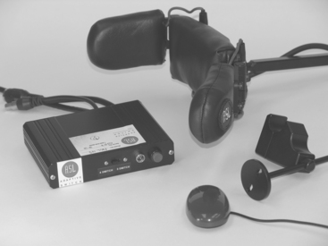
Various head control systems are available, arranged in a head array in a headrest. Figure 12-15 shows an example of this type of control interface. These are electronic, not mechanical, switches. Typically the user has access to three switches: moving the head backward causes the chair to move forward, tilting it to the right moves the chair right, and the opposite initiates travel to the left. Tilting the head forward stops the chair (Lange, 2005). Control can be either proportional or nonproportional depending on the head control of the user. Individuals who tend to move into extension when their neck is extended may not be good candidates for this type of system because they may not be able to reliably stop or reverse the chair if extensor tone inhibits forward flexion of the neck.
Magitek (www.magitek.com) produces a head control system that uses a 360-degree tilt sensor mechanism (Cole, 2004). These sensors detect tilt in the lateral and anterior/posterior planes. It is usually attached to a headband, but it can be attached to other body parts. This system is a useful alternative for an individual with adequate head control who tends to go into extension with neck extension.
Indirect selection using scanning is also available for consumers who can only use a single switch. In this case there are four lights, one for each direction, arranged in a cross pattern. The lights scan around the pattern until the user presses the switch. The wheelchair then moves in the direction selected. Other functions (e.g., high-low range) are also scanned. Single-switch scanning is time consuming and cognitively demanding and should be considered for power wheelchair control only after other options have been excluded.
Controllers.
A power wheelchair controller connects the control interface to the drive system. This component is the processor in the assistive technology component of our HAAT model. Figure 12-16 shows a typical wheelchair controller. In a proportional drive system the controller determines the amount of voltage to supply to the motor by the amount of deflection in the joystick, and this voltage is directly related to motor speed. In a switched control system this type of proportionality is not obtained from the control interface. To allow the wheelchair to accelerate gradually (as the user with a proportional control would do), the controller provides a gradual acceleration when any direction is selected. In most controllers the rate of acceleration can be adjusted to meet the consumer’s needs. For example, an expert power wheelchair user could have the acceleration set on the high end so that the chair is highly responsive, whereas a novice user could set the rate of acceleration slower to allow for a slower start. The rate of deceleration (braking) can also be adjusted. Deceleration is the swiftness with which the wheelchair comes to a stop once the control interface is deactivated. With these two features on a controller, it is possible to set one rate for acceleration and a different rate for braking.
Controllers also provide either momentary or latched switch control. In momentary control the motors are activated only while the switch is pressed, which provides the greatest control for the user. Some consumers are unable to maintain switch activation, but they can press and release quickly. In this case latched control is used. In this mode, when the switch is pressed once, the motors turn on and remain on. When the switch is pressed again, the motors turn off. It is important that the consumer be able to activate the switch reliably and rapidly when it is in the latched mode, so as to stop quickly when necessary. This feature is often used with sip-and-puff switches. It allows the user to give a hard puff once to latch the control for the wheelchair to move either forward or backward and then use soft sips and puffs to turn left or right (Taylor and Kreutz, 1997).
Most powered wheelchair controllers are programmable by the user to some extent, which gives them much more flexibility and adjustability. Forward and reverse maximal speeds can be independently adjusted. On some devices the ratio of forward to reverse speed is selected. It is more difficult to control the wheelchair when turning than when going straight, and the controller feature that allows turning speed to be set independently of (or as a function of) forward speed is useful.
Some consumers have difficulty controlling their movements because of tremor, which can make the use of a joystick or other wheelchair control interface difficult. To accommodate for tremor, an averaging feature is incorporated into some controllers. The averaging system effectively damps out the tremor by ignoring small rapid movements and responding to larger, slower ones (Aylor et al, 1979). The disadvantage of this approach is that the system can become sluggish, resulting in reduced capability to respond to obstacles quickly. This feature is sometimes referred to as the sensitivity or tremor dampening of the controller.
Another adjustment allowed by the controller is the ability to alter the degree of range of motion required for an individual to operate a control interface. This is called the short throw adjustment and is most commonly used with joysticks. This feature is useful for consumers who have limited range of motion at the control site that is being used. Some current controller models have an LED display that visually represents the different functions and the results of adjustments as they are made.
Computer-based controllers allow the storage of a set of values for parameters such as those described earlier. These parameters can then be recalled for use in a particular situation (e.g., outdoors on a hill or indoors on a smooth floor). A therapist working with a consumer to gradually develop driving skills can also store the setups and recall them when needed. In training or assessment settings where several consumers may use one powered wheelchair, there can be different configurations stored for each consumer. Most power wheelchair controllers also have provision for the attachment of an “attendant control,” which is very useful for training. This control can override the user’s control interface in an emergency situation.
Another feature of many controllers is the ability to operate different functions of the wheelchair or other devices with the same control interface. Generally, an output from the controller is connected to the external device (e.g., an augmentative communication system or electronic aid to daily living). These outputs may be called auxiliary or ECU on different commercial wheelchair controllers. By using a switch, the user is able to transfer the output of the controller from the motors to the external device. The control interface is then able to control the external device directly. A visual display identifies which function is being used. For example, if a joystick were being used for mobility, then switching to communication would allow directed scanning (see Chapter 7) to be used for selections on an augmentative communication device. A switch would allow the user to change between these two operations.
Batteries.
The power for a power wheelchair is supplied by a pair of batteries that are mounted under the seat of the chair. The batteries used are rechargeable lead-acid types. The name comes from the suspension of lead plates in a solution of sulfuric acid. There are two plates. The positive terminal is called the cathode and the negative plate is the anode; the size of the plates determines how much current can be drawn from the plate. When the wheelchair controller and motors are attached to the battery and turned on, current is drawn out of the battery, which causes current to flow from the negative terminal to the positive terminal. Inside the battery, chemicals from the acid solution are deposited on the plates. When a majority of the chemicals have moved out of the solution, the battery is discharged. Applying an external current to the battery terminals with a battery charger reverses the process and causes the deposited materials to move back into solution, which recharges the battery.
Batteries differ in several ways. Automobile batteries require a high current for a short period to start the car. Wheelchair batteries, on the other hand, require smaller amounts of current for a longer time. This difference is reflected in the use of deep-cycle lead-acid batteries for power wheelchairs. These have thicker plates, which allow them to provide current for longer periods. The chemicals inside the battery may be in a liquid form, called a wet cell, or in a semisolid form, called a gel. Wet-cell batteries are less expensive and last longer; however, they are more hazardous and require more maintenance than gel batteries so are less commonly used for powered wheelchairs. The fluid in wet-cell batteries is subject to spilling and evaporation. Replacement of the fluid with distilled water is required at regular intervals. Gel (often called sealed) batteries will not spill, which makes them more desirable for transportation. They do not require any maintenance other than keeping them charged. These batteries are typically allowed on public transportation systems, whereas the wet cell batteries often are not. They do not need to be fully discharged before they require recharging. They do not have a “memory,” which means that the battery capacity is not limited by previous recharges. Battery power between charges is determined by the capacity measured in ampere-hours. At room temperature, wheelchair batteries commonly have 30 to 90 ampere-hours capacity at 12 volts (Cooper, 1998). The type of motors, environmental conditions (e.g., extremes of temperature), and amount of regular maintenance can all affect battery life and performance. Different batteries require different types of chargers, and it is imperative that the correct battery charger be used. The technology for wheelchair batteries has changed very little over the years. Smaller, lighter-weight batteries with an increase in capacity would help to decrease the weight of power wheelchairs and increase the distance that the user can travel on one charge.
ANSI/RESNA standards identify a test method for determining the capacity of wheelchair batteries on a single charge. This test requires the chair to be driven at maximum speed around a 54.5 m track 10 times in each direction. Amperes per hour are measured and the theoretical maximum distance is calculated from this measurement (ANSI/RESNA, 1998). Rentschler et al (2004) indicate that this test does not take into account the varying draw on battery power when the user travels up hill, in different weather conditions or across different terrains, for example. Information on the theoretical distance of a battery is vital information because serious injury or death could result from a power wheelchair user who is stranded by a dead battery.
Ventilators.
Consideration must be given to the placement and movement of a ventilator when the power wheelchair user is dependent for respiratory support. Like many other products, ventilators have become much more compact and streamlined in recent years, yet they still affect the overall length, weight, and center of mass of the chair. Ventilators can be mounted low on the base of the chair or on a frame that is attached to the vertical uprights of the back. Mounts for ventilators can be fixed or articulating. The orientation of the ventilator is congruent with that of the wheelchair seat in a fixed mount. An articulating mount is required with tilt or recline features of the seating system. This option maintains the vertical orientation of the ventilator as the seat moves in tilt or recline modes. Further, it keeps the ventilator out of the way of the chair batteries.
Specialized Bases for Manual Wheelchairs
The major wheelchair characteristics have been described; now dependent mobility bases that have unique structural and propelling characteristics will be discussed. Because an attendant or care provider is responsible for pushing the consumer in a dependent-mobility wheelchair, special attention is given to making this action as easy as possible. Items normally required for independent manual mobility (e.g., large rear wheels with hand rims) are often omitted in these systems. Bases for dependent mobility are commonly lighter in weight and lower priced than wheelchairs for independent manual mobility (Trefler et al, 1993).
Stroller Bases.
Strollers, similar to those used for transporting very young children, are typically of two types: (1) umbrella folding with a sling seat and (2) full-sized units with solid seats (Trefler et al, 1993). Although originally designed for children, there are now strollers that accommodate consumers who weigh up to 200 pounds. The umbrella type generally does not provide good sitting support, but it folds easily for storage in a vehicle. Consumers who use strollers should not be transported in the stroller unless it has been crash tested (Kemper, 1993). The lightweight construction of some units makes the attachment of solid seating systems difficult; however, on other units it is possible to attach seating components. Some of these seating components can be removed from the stroller base and used as car seats.
More solidly built stroller bases that can accommodate specialized seating systems (see Chapter 6) are available from several manufacturers. In some cases these systems have provision for growth. The most common approach is to use a frame large enough to accommodate a few years’ growth and then add components that keep the child in a stable and functional position.
Another attraction of stroller bases is that they resemble standard strollers in appearance, which can be appealing to parents. One feature that appeals to parents is the ease with which they can be transported. The small wheels and short wheelbase of most strollers makes them easily maneuverable by an attendant. One disadvantage of the stroller is that the child is often in a reclined position, which may limit his ability to carry out functional tasks. Strollers are sometimes purchased as a second wheelchair to facilitate transportation, with a standard wheelchair used for functional tasks.
Transport Wheelchairs.
Transport wheelchairs are designed for occasional use, often available for transporting patients in hospitals or in short-term situations such as traversing an airport or shopping mall. They typically have upholstery seating and four small wheels. They do not have any adjustability nor is it anticipated that seating systems will be used. They are lightweight, durable, and relatively maintenance free. These chairs provide a dependent mobility option and are not intended to provide seating and positioning in the long term.
Wheelchairs for Use by Older Clients.
The setup of a manual wheelchair for regular use by an older client is different from that of a younger, more active user. Age-related disabilities such as arthritis, osteoporosis, and osteopenia contribute to reduced muscle strength and range of motion. Further, older clients may feel less secure in their movements. Age-related visual changes, including disorders such as age-related macular degeneration and glaucoma, are further considerations for setup of a chair for use by an older client. Care should be taken to ensure that the center of gravity ratio of the client to the axis of the drive wheel provides an optimal stability and mobility balance. Access to the drive wheels and hand rims relative to range of motion and strength in the upper extremities needs to be considered along with rolling resistance. Effects of visual-perceptual changes resulting from a cerebral vascular accident will affect the user’s ability to navigate in the environment and will need to be considered when providing training in wheelchair skills.
Some manufacturers are producing chairs that have a rocking feature. Often these chairs have a tilt feature as well. A mechanism on the chair allows the user to rock the seat of the chair. This mechanism can be disengaged in some situations, such as transportation, when it is not desired. This feature is recommended for clients who become agitated with the view that the rocking motion is calming for the client.
Wheelchairs for Bariatric Clients.
Bariatric clients, those individuals with a BMI of 30 or greater, were identified as a population with an increasing prevalence in North America. These individuals require frames that are designed to accommodate their weights and their larger sizes. Most typical wheelchairs have a maximum weight capacity of 300 pounds. Chairs for bariatric clients accommodate a maximum weight of 600 pounds, with some manufacturers offering chairs that will accommodate up to 1000 pounds (Daus, 2003). The location of the mechanics of electrically powered wheelchairs beneath the seat allows the use of a larger seat while still maintaining as narrow a width as possible. Some chairs provide user adjustable seat depth and width. Tilt is also an option that can be provided for the bariatric client. The Eclipse (Figure 12-17) is an example of a chair designed for bariatric clients.
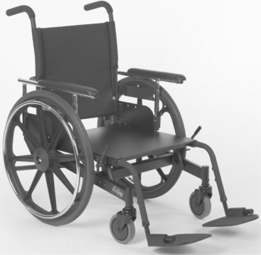
Fitting a wheelchair for a bariatric client has special considerations because soft tissue distribution and accumulation are varied, resulting in different body sizes and shapes (Daus, 2003). Measurement should be done with the client in the seated position, on a firm surface. If there is significant soft tissue accumulation around the buttocks, the configuration of the seat back must be considered because the buttocks may protrude further than the shoulders, requiring the individual to lean back if the upper back is to be in contact with the seat back. Some manufacturers produce a back that provides support along the entire back surface. A change in the width of the back from hip to shoulder to accommodate a different shape is another accommodation made by some manufacturers.
Specialized Bases for Electrically Powered Wheelchairs
A significantly different approach to powered mobility is incorporated in the INDEPENDENCE 4000 iBOT mobility system, shown in Figure 12-18. In this approach an electronic balance system is used, which allows the mobility system to be customized for a user’s size, weight, and center of gravity. By use of a complex set of gyroscopes and computer-controlled electronics, the INDEPENDENCE 4000 constantly adjusts its position to ensure that the user remains balanced and stable regardless of the terrain, movements of the user, or functions of the device. There are five functions for the device: standard, four-wheel, stair, balance, and remote. In its standard function the INDEPENDENCE 4000 drive wheels are in the rear position. In its four-wheel function (Figure 12-18, A and B), the INDEPENDENCE 4000 can navigate uneven surfaces, travel through sand and gravel, and climb over street curbs. In each of these activities the user is kept in a horizontal position and is balanced and stable. This function significantly expands the recreational options for users because they can visit the beach, go over hiking trails, and cross grass fields. Uneven pavement, cobblestone sidewalks, and other similar obstacles can also be navigated with the INDEPENDENCE 4000 in four-wheel function. In the stair function (Figure 12-18, C) the INDEPENDENCE 4000 is able to go up or down flights of stairs, although users must have sufficient upper extremity strength to stabilize themselves with handrails. If the user lacks this capability, a trained assistant can provide the necessary help for stair climbing.
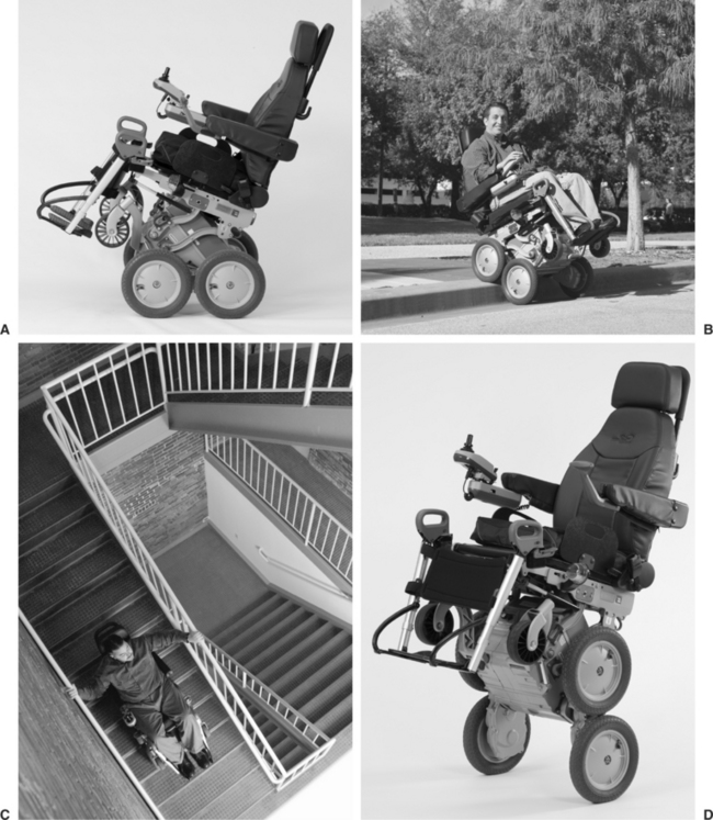
Figure 12-18 INDEPENDENCE® iBOT® Mobility System. A, Standard function. B, Four-wheel function. C, Stair function. D, Balance function. (Courtesy Independence Technology, a Johnson & Johnson Company.)
The most unique feature of the INDEPENDENCE 4000 is its balance function (Figure 12-18, D). In this function the INDEPENDENCE 4000 uses its control system to balance the system on two wheels, which has several advantages. First, the user is raised to eye level, a significant factor for many individuals with mobility needs. Second, the balance function allows the user to reach objects on shelves, to reach the back of counters, and to generally function in a manner closer to that of standing. While in balance function, the INDEPENDENCE 4000 can be controlled by the joystick interface, just like a power wheelchair. Finally, remote function allows the user to transfer out of the INDEPENDENCE 4000, fold down the seat, and unlatch the control interface (joystick, keypad, and display). The INDEPENDENCE 4000 is tethered to the control with a cable and can be “driven” slowly, which allows the user to drive the INDEPENDENCE 4000 into the rear of a van (up a ramp with up to a 25-degree slope) for transportation.
Eligibility criteria have been established for purchase of the INDEPENDENCE 4000 on the basis of physical needs either required to operate the device or that exclude the safe use of the device (i.e., physical needs of the consumer that cannot be accommodated by the device). Requirements for safe operation of the device include a weight range of 75 to 250 pounds and ability to operate a push button telephone and control a joystick. Needs or functions of the user that exclude their use of the iBOT mobility system include need for tilt and recline, use of a ventilator, inability to sit upright and reach the foot plates, and bone conditions that place the individual at high risk for fracture (Independence Technology, 2005).
A small study has been completed that evaluated the ability of individuals with disabilities to safely and effectively use the device and to determine whether it improved function (Uusatal and Minkel, 2004). Twenty subjects with a variety of disabling conditions who regularly used a mobility device participated in the study. The INDEPENDENCE 3000 was used for a period of 2 weeks after successful completion of a training program for the device. Outcome measures included the number of reported adverse events and the Community Driving Test, which was designed for this study. Comparison was made between performance with the iBOT mobility system and their typical devices. No difference was found for reported adverse events. The four-wheel drive and stair-climbing options provided significantly better function than the users’ typical devices (Uusatal and Minkel, 2004). This study provides preliminary support for the benefits of this device. A large multicenter evaluation is currently in progress.
Customizable Electrically Powered Wheelchairs.
The range and combinations of features available on electrically powered wheelchairs is rapidly increasing. Some of these features, such as tilt, recline, elevating seats, and footrests have been mentioned already. The Attitude and the Latitude systems (Figure 12-19, A and B) both provide power options to enable independent transfers. The Attitude has a foot platform that lowers to the ground and then raises up to seat height, allowing an individual to transfer independently. To transfer into the chair, the foot platform is lowered to the floor; the user transfers onto the foot platform, raises it to seat height, and then transfers on to the seat. The Latitude system is similar, but the entire seat moves forward and down to the floor.
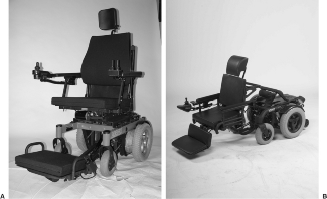
Smart Wheelchairs.
Smart technology is being incorporated into wheelchairs to provide additional options for individuals who are unable to control a wheelchair in other ways. Smart wheelchairs are defined as “either a standard power wheelchair to which a computer and a collection of sensors have been added or a mobile robot base to which a seat has been attached” (Simpson, 2005, p. 424). These technologies are useful for wheelchair users who have low vision or a severely restricted visual field, motor impairments such as excessive tone or tremor, or cognitive impairments that limit their ability to navigate a wheelchair safely. Smart technologies can be integrated into the available power system or built as an add-on feature (Simpson, 2005).
Smart wheelchairs typically provide three functions: collision avoidance, navigation along walls or through doorways, and navigation from one place to another. In the latter situation, the wheelchair has an internal map of the individual’s environment, allowing the user to move from one programmed start place to an end point. The user must have some control of the chair because collision avoidance is not a feature with this navigation function. Input to the system is through a joystick or other control interfaces as described earlier, voice input, or more sophisticated means such as perception of head position or eye gaze. The NavChair (Levine et al, 1999) is one example of a wheelchair that uses smart technology. It has three functions: collision avoidance, navigation through a doorway, and travel along a wall.
Four main types of sensors are used to guide the chair: infrared (see Chapter 14 for a further explanation of this type of sensor), sonar (sound wave technology), laser range finders, and computer vision (Simpson, 2005). As might be anticipated, the cost of these systems is extremely high and consequently they are very limited in their commercial availability. Most of their use is in a research setting at this time. Like the sophisticated sensor and navigation technology for the automobile, however, this technology is becoming increasingly more accessible, so we can anticipate that these functions will be available in the future.
Scooters.
Scooter wheelchairs (Figure 12-20) comprise a large proportion of the electrically powered systems on the market. Individuals who are marginal ambulators and need mobility to conserve energy most often use the scooter. For this reason, it is most commonly used by the consumer outside the home. Grocery stores and shopping malls often provide scooters for customers who may need them. The propelling structure of the scooter includes the drive train, the tires, the tiller, and the battery. There are a number of models available, in either three- or four-wheel versions, with front-wheel drive or rear-wheel drive. Scooters with front-wheel drive do better on level terrain and are more maneuverable. For this reason, they perform better in small spaces. In rear-wheel drive scooters, the rider’s weight is positioned over the motor, so there is better traction and more power. The bases of rear-wheel drive scooters are wider and longer than the other powered chairs. These scooters are better able to handle inclines and uneven or rough terrain and therefore are preferable for outdoor use.
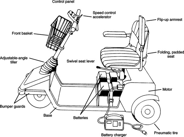
A tiller-type control is used to steer the wheelchair, and acceleration is accomplished by either grasping a lever on the tiller with the fingers or pressing with the thumb. When the accelerator is released, the scooter eases to a stop. On some scooters the height and angle of the tiller is adjustable. Depending on the model, scooters can have either proportional (variable speed) control or switched (constant speed) control. There is a separate control setting for adjusting the speed of the scooter. Some scooters have a dial that provides a range of settings, whereas others have a toggle switch for high and low.
The seat of the scooter is mounted to a single post coming up from the base. Typically the seat is a bucket type that has few options for seat width, depth, or back height (Toonstra and Barnicle, 1993). The seats come in padded or unpadded versions, and several types of armrest styles (fixed, flip-up, or none) are available. In the past, if a person needed a specialized seating or positioning system, it was not possible to interface it to a scooter. There are now some scooters that can accommodate specialized seating equipment. On most scooters there is a mechanism that releases the seat so it can swivel to the side and then locks it in place again. This feature is helpful for transfers in and out of the seat and for accessing a table surface.
Some of the advantages of scooters are that they are lighter in weight, can be disassembled for transportation in a car, are easy to maneuver, are less costly than other power wheelchairs, and are more acceptable than other types of power wheelchairs. The primary disadvantage of scooters is that they do not provide flexibility in control interfaces. The consumer needs to have a fair amount of trunk and upper extremity control to operate the tiller of the scooter. Scooters also have very little flexibility in terms of speed, braking, or turning control. Finally, the seat of a scooter typically does not provide adequate postural support, and many types of seating systems needed by individuals with postural control problems cannot be interfaced to a scooter.
Power-assist Mechanisms.
Considerable attention has been given to the shoulder injuries that result from prolonged propulsion of a manual wheelchair (for example see Boninger et al, 2002, 2005; Cooper et al, 1997b; Sawatsky et al, 2005; Veeger et al, 2002). One option for individuals with shoulder pain that limits the ability to propel a manual wheelchair but for whom an electrically powered wheelchair is not desirable is push rim–activated power-assist wheels. These wheels are interchanged with those of a manual wheelchair. A motor is located in the hub of the rear wheels that is linked to the hand rims (Algood et al, 2005). These units supply power to the manual wheelchair as needed by the user. When the user applies force above a preset level to the hand rims, such as when going up an incline, the motors engage and help to propel the wheelchair. Propulsion and braking assistance are provided for both forward and rearward motion. The unit can also be turned off, which allows the manual wheelchair to function in the usual manner. These units add considerable weight to a manual chair, which is a consideration in their selection.
A new product on the market with a similar purpose is Magic Wheels, which provides geared technology for manual wheelchairs (Figure 12-21). Magic Wheels gives the user a selection of two gears, similar to the concept of bicycle gears, with the second gear providing a 2:1 mechanical advantage. The user selects the second gear by moving the housing of the gear, located on the hub of the wheel. Changing gears does not require grip or substantial strength. Magic Wheels are most useful on inclines, where they provide assistance propelling upward and braking when traveling downward. Finley et al (2006) completed a pilot study of the effect of Magic Wheels use on shoulder pain, length of time the user was able to sustain uphill travel, and perceived exertion during this task. An A-B-A design was used, with baseline being use of consumer’s typical wheels. After 4 months of use, shoulder pain was stable or reduced, and users were able to travel uphill for a longer time with no change in perceived exertion.
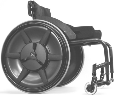
Wheelchair Standards
As discussed in Chapter 1, standards can be used to provide manufacturing guidance to ensure product quality. One area of assistive technologies in which standards have been developed is for wheelchairs. Both the International Standards Organization (ISO) and ANSI and RESNA have published standards for manual and power wheelchairs, seating systems, and wheelchair use during transportation. There is considerable overlap in these standards. A comparison of the ISO and ANSI/RESNA standards is shown in Box 12-3. Although these standards are voluntary, there are strong motivations for manufacturers to adhere to them. For example, the Department of Veterans Affairs (VA) has purchasing requirements for wheelchairs. As the largest purchaser of wheelchairs in the United States, the VA could significantly affect compliance with the standards shown in Box 12-3 by adopting them by reference, rather than developing their own standards. Some published studies exist that have applied these standards to manual and electrically powered wheelchairs and seating cushions (for example, see Cooper et al 1997a, 1999; Fass et al, 2004; Pearlman et al, 2005; Rentschler et al, 2004; Sprigle and Press, 2003).
BOX 12-3 Comparison of ISO and ANSI/RESNA Wheelchair Standards
| Standard | ISO | ANSI/RESNA |
| Nomenclature, terms, and definitions |  |
|
| Determination of static stability | |
|
| Determination of overall dimensions, mass, and turning space | |
|
| Determination of seating and wheel dimensions | |
|
| Static, impact, and fatigue strengths | |
|
| Test dummies | |
|
| Determination of coefficient of friction of test surfaces | |
|
| Requirements for information disclosures, documentation, and labeling | |
|
| Determination of flammability | |
|
| Wheelchairs used as seats in motor vehicles | |
|
| Wheeled mobility devices for use in motor vehicles | |
|
| Determination of performance of stand-up wheelchairs | |
|
| Setup procedures | |
|
| Maximum overall dimensions | |
|
| Determination of dynamic stability of electric wheelchairs | |
|
| Determination of efficiency of brakes | |
|
| Energy consumption of electric wheelchairs and scooters for determination of theoretical distance range (ISO) | |
|
| Determination of maximum speed, acceleration and retardation of electric wheelchair | |
|
| Climatic tests for electric wheelchairs | |
|
| Determination of obstacle climbing ability for electric wheelchairs | |
|
| Testing of power and control systems for electric wheelchairs | |
|
| Requirements and test methods for electromagnetic components of power wheelchairs and motorized scooters | |
|
| Requirements and test methods for attendant-operated stair-climbing devices | |
|
| Requirements and test methods for user-operated stair-climbing devices | |
IMPLEMENTATION AND TRAINING FOR MANUAL AND POWERED MOBILITY
As we have emphasized throughout this text, the assistive technology system includes much more than a piece of equipment. For the consumer to be satisfied and successful with an assistive device, proper implementation and training need to be part of the system. The same holds true to maximize the performance of consumers who use mobility systems.
Fitting of Mobility Systems
It is advisable that a fitting appointment be held with the consumer and caregiver. The purpose of this appointment is to make any adjustments needed to the wheelchair and to try the chair and determine whether it meets the original objectives outlined during the assessment. During the initial fitting, time should also be spent demonstrating to the user and the care giver important features of the chair and going through instructions for maintenance. Box 12-4 shows a checklist of items to be covered during the fitting process for either a manual or power wheelchair. Depending on the complexity of the wheelchair and whether seating components are involved, more than one fitting appointment may be necessary.
Because today’s wheelchairs are often multifunctional, a number of components on the wheelchair are adjustable. Some adjustments and settings are made in the factory before shipping, but typically the provider of the wheelchair will need to make modifications to fit the chair to the user once it arrives from the factory. Adjustments to the wheelchair that can make a difference in user comfort, safety, and performance include axle position, wheel camber, and wheel alignment. Appropriate adjustment of the seat angle, back height and angle, and height and angle of leg rests and footrests are also critical to user performance. Cooper (1998) and Ham, Aldersea, and Porter (1998) describe in detail how to make each of these adjustments. Any adjustments to the chair should be made carefully and with the user’s safety in mind. After adjustments are made, the user should be cautious in trying out the wheelchair until he or she becomes acclimated to the changes.
Maintenance and Repair of Personal Mobility Systems
Wheelchairs are designed to be low maintenance, and there are few items on a wheelchair, particularly a manual wheelchair, that require maintenance by the user (Cooper, 1998). The user is responsible for keeping the chair clean, the tires properly inflated, and the brakes properly adjusted and for seeing that the wheelchair is inspected on a regular basis. The user of an electrically powered wheelchair needs to ensure that the correct battery for the wheelchair is used and that it is properly charged. A checklist of items that wheelchair users should monitor or have monitored regularly is shown in Box 12-5. The user manual for the wheelchair will also specify a schedule for periodic inspection and maintenance. A reputable assistive technology supplier should complete any maintenance that needs to be done on the wheelchair.

Developing Mobility Skills for Manual and Powered Systems
Training in mobility skills can occur before and after the delivery of the final chair to the consumer. In situations where it is undetermined which chair is most suitable for the consumer or whether the consumer will be able to operate the wheelchair, a trial period takes place. During the trial period the person is loaned or leased a wheelchair, either manual or power, which allows the consumer to test the chair and determine whether it is appropriate to meet his or her needs. Often, particularly with powered mobility, this trial involves a period of training to determine whether the person can develop the skills to use the wheelchair. For example, powered mobility may be identified as a goal, but the individual may not yet have the skills required to control a power wheelchair safely. If there is any question, it is best to delay making an expensive equipment purchase and risking the safety of the user and others. It is important that the potential user develop these skills through a training program before permanently acquiring the device. Implementation does not always end with the consumer’s acquisition of the device. In many cases, further training sessions are necessary. In development of either manual or powered mobility skills, it is important to set specific, measurable objectives for training.
For manual mobility, basic skills include maneuvering the wheelchair indoors on a level surface, in and around tight spaces, and over surfaces such as carpet, tile, or linoleum. For the active user of a manual wheelchair, preparation in advanced wheelchair mobility skills is suggested. These include the ability to negotiate rough, uneven terrain; propel up and down ramps and curbs independently; and execute “wheelies.” The Manual Wheelchair Training Guide (Axelson et al, 1998) provides information on basic wheelchair setup and maneuvering the wheelchair in indoor and outdoor environments.
One well-researched training program, the Wheelchair Skills Program (Kirby, 2005), is available from www.wheelchairskillsprogram.ca. This program was developed in conjunction with the Wheelchair Skills Test (Kirby et al, 2002, 2004). The program teaches wheelchair users basic use of the wheelchair, such as applying and releasing the brakes, removing footrests, and folding the chair. It teaches basic propulsion such as rolling forward and backward, turning, and maneuvering through doorways. More advanced skills include propulsion on an incline, level changes, performance of a wheelie, and various wheelie skills. Skills are classified as indoor, community, or advanced (Kirby, 2005).
As with the skills required for driving an automobile, successful powered mobility use requires training and practice, which applies to everyone who uses a power wheelchair. A systematic approach that develops these skills and progresses in small increments is most likely to be successful. As with manual mobility, the training in powered mobility skills should progress from basic skills to more complex skills and situations. Some schools purchase a power wheelchair that can be used with various control interfaces and seating systems. It is then possible to use the wheelchair with different children for training as needed. For young children, it is recommended that training be fun, starting with a toy cart and moving to a wheelchair base as appropriate (Barnes, 1991). Many children’s games can be adapted to develop skills needed in powered mobility training, such as “red light, green light” for learning how to stop on command. Computer activities can also apply to the development of powered mobility skills; these are discussed in Chapter 7.
The development of powered mobility skills in young children can be described as progressing in three stages: stage I, exploratory; stage II, directive; and stage III, purposeful (Janeschild, 1997). In stage I, the exploratory stage, the child is encouraged to explore mobility in an environment that is safe and motivating. The goal is for the child to explore and learn how to control the mobility device. The trainer gives verbal feedback as it relates to what the child is doing at the moment and only to reinforce simple mobility concepts; for example, “You are moving closer to your mommy.” The purpose of this stage is to minimize the amount of verbal direction given to the child and to maximize the child’s interest in interacting with the environment. During stage II, the directive stage, the goal is for the child to use the mobility device to move in the general area of a target. In the purposeful stage (stage III), the skills learned by the child are applied to home and school contexts in which more constraints are placed on the situation. Janeschild (1997) presents a tool for documenting the child’s progress through the three stages.
SUMMARY
Mobility is very important for participation in self-care, home, work, school, and leisure activities. Mobility needs for individuals with disabilities vary depending on the age and the disability status of the user. In this chapter we describe the general characteristics of personal mobility systems and the various types of mobility devices available to meet individual needs of the user. Personal mobility devices fall under the categories of independent manual, dependent manual, and powered mobility. Both manual and electrically powered wheelchair options were described. With the plethora of personal mobility options that are available, the ATP requires thorough assessment and evaluation processes, considering all the elements of the HAAT model, to ensure the most appropriate initial recommendation for and the continuing utility of the mobility device.
1. On the basis of consumer needs, what are the three categories of mobility bases?
2. What factors are considered as part of a wheelchair evaluation?
3. In what situations may powered mobility be considered?
4. What are the two major structures of a wheelchair?
5. Describe and contrast the advantages and disadvantages of tilt versus recline systems. What are the indications for the recommendation of each?
6. Discuss the relationship of the center of mass of the user to the center of mass of the wheelchair as it was described in the various sections of this chapter. What are the implications of this relationship to function?
7. What are the ways in which pediatric wheelchairs can accommodate growth?
8. List the four types of standing systems and give an advantage and disadvantage of each. What are the major benefits of these systems?
9. Describe the major considerations in choosing manual wheelchair tires, wheels, and casters. List the major options available for each.
10. Define camber and describe indications for its use and how it affects the function of a manual wheelchair.
11. Define bariatrics and discuss the implications of wheelchair prescription and configuration for this population.
12. Discuss the considerations of wheelchair prescription and configuration for elderly clients.
13. Identify the different locations of the drive wheels of an electrically powered wheelchair and describe how each affects the function of the chair.
14. What types of control interfaces are typically used for powered wheelchairs?
15. Delineate the major functions of a wheelchair controller. What additional features do computer-controlled units provide?
16. What special considerations are important in considering the inclusion of ventilators on a wheelchair?
17. What types of batteries are used in power wheelchairs? How do they differ from automobile batteries? What is the difference between wet cell and gel batteries?
18. Why are wheelchair standards important? Name three major elements covered in the wheelchair standards.
19. Describe what should happen during the implementation phase for a powered mobility device.
References
Algood, SD, et al. Effect of a pushrim-activated power-assist wheelchair on the functional capabilities of persons with tetraplegia. Arch Phys Med Rehabil. 2005;86:380–386.
American National Standards Institute/Rehabilitation Engineering and Assistive Society of America. Wheelchair standards: additional requirements for wheelchairs (including scooters) with electrical systems, New York, ANSI/RESNA, 1998;vol 2:.
Axelson, P, et al. The manual wheelchair training guide. Santa Cruz, CA: Pax Press, 1998.
Aylor, J, et al. Versatile wheelchair control system. Med Biol Eng Comput. 1979;17:110–114.
Barnes, KH. Training young children for powered mobility. Dev Disabil Spec Interest Sect Newsl. 14, 1991.
Belanger, A, Martel, L, Caron-Malenfant, E. Population projections for Canada, provinces and territories, 2005-2031. Ottawa, ON: Ministry of Industry, 2005.
Boninger, M, et al. Propulsion patterns and pushrim biomechanics in manual wheelchair propulsion. Arch Phys Med Rehabil. 2002;83:718–723.
Boninger, M, et al. Pushrim biomechanics and injury prevention in spinal cord injury: recommendations based on CULP-SCI investigations. J Rehabil Res Dev. 2005;42:9–20.
Bureau of the Census: U.S. interim projections by age, sex, race, and Hispanic origin, Table 2a, Projected population of the United States, by age and sex: 2000 to 2050 (March 2004): www.census.gov/ipc/www/usinterimproj/natprojtab02a.pdf. Accessed October 29, 2006.
Butler, C. Wheelchair toddlers. In: Furumasu J, ed. Pediatric powered mobility: developmental perspectives, technical issues, clinical approaches. Arlington, VA: RESNA Press, 1997.
Centers for Disease Control and Prevention. State-specific prevalence of obesity among adults—United States, 2005. Morb Mortal Wkly Rep. 2006;55(36):985–988.
Cole, E. Selecting controls for power wheelchairs. In: Proceedings of the 20th International Seating Symposium. Vancouver: British Columbia; 2004:179–187.
Cooper, RA. Wheelchair selection and configuration. New York: Demos Medical Publishing, 1998.
Cooper, RA, et al. Performance of selected lightweight wheelchairs on ANSI/RESNA tests. Arch Phys Med Rehabil. 1997;78:1138–1144.
Cooper, RA, et al. Methods for determining three-dimensional wheelchair pushrim forces and moment—a technical note. J Rehabil Res Dev. 1997;38(1):41–55.
Cossette, L. A profile of disability in Canada, 2001. Ottawa, ON: Ministry of Industry, 2002.
Daus, C. The right fit, Rehabilitation Management. http://www.rehabpub.com/features/892003/4.asp, 2003. [Accessed October 31, 2006.].
Denison, I, Gayton, D. Power wheelchairs selection. http://www.assistive-technology.ca/newdef2.htm, 2002. [Accessed October 28, 2006.].
Deitz, JC. Pediatric augmented mobility. In: Gray DB, Quatrano LA, Lieberman ML, eds. Designing and using assistive technology: the human perspective. Baltimore: Paul H Brookes, 1998.
Eng, JJ. Getting up goals, Rehabilitation Management. http://rehabpub.com/features/1022004/5.asp, 2004. [Accessed October 28, 2006.].
Engstrom, B. Ergonomic seating: a true challenge. Sweden: Posturalis Books, 2002.
Fass, MV, et al. Durability, value and reliability of selected electric powered wheelchairs. Arch Phys Med Rehabil. 2004;85:805–814.
Fields, CD. Groundwork: Casters. Team Rehabil Rep. 1992;3:22–23. [33].
Finley MA et al: Effect of 2-speed manual wheelchair wheel on shoulder pain in wheelchair users: Preliminary findings. In Proceedings of the 22nd International Seating Symposium, 2006, Vancouver, British Columbia.
Ham, R, Aldersea, P, Porter, D. Wheelchair users and postural seating: a clinical approach. New York: Churchill Livingstone, 1998.
Hobson, DA. Seating and mobility for the severely disabled. In: Smith RV, Leslie JH, eds. Rehabilitation engineering. Boca Raton, FL: CRC Press, 1990.
Independence Technology. iBOT Mobility System: FAQ. http://www.ibotnow.com/ibot/faq.html. [Accessed November 4, 2006.].
Janeschild, M. Early power mobility: evaluation and training guidelines. In: Furumasu J, ed. Pediatric powered mobility: developmental perspectives, technical issues, clinical approaches. Arlington, VA: RESNA Press, 1997.
Kaye, S, Kang, T, LaPlante, MP. Wheelchair use in the United States. Disab Stat Abst. 2002;23:1–4.
Kemper, K. Strollers: a growing alternative. Team Rehabil Rep. 1993;4:15–19.
Kermoian, R. Locomotor experience facilitates psychological functioning: implications for assistive mobility for young children. In: Gray DB, Quatrano LA, Lieberman ML, eds. Designing and using assistive technology. Baltimore: Paul H Brookes, 1998.
Kirby, RL. Wheelchair skills program v. 3.2. www.wheelchairskillsprogram.ca, 2005. [Accessed October 30, 2006.].
Kirby, RL, et al. The wheelchair skills test: a pilot study of a new outcome measure. Arch Phys Med Rehabil. 2002;83:1298–1305.
Kirby, RL, et al. The Wheelchair Skills Test (version 2.4): measurement properties. Arch Phys Med Rehabil. 2004;85:41–50.
Kreutz, D. Power tilt, recline or both. Team Rehabil Rep. 1997;8:29–32.
Lacoste M et al: Identifying elderly wheelchair users’ needs: results of a focus group. In Proceedings of the RESNA ’98 Annual Conference, pp 158-160, 1998, Washington, DC, RESNA.
Lange, M. Tilt in space versus recline: new trends in an old debate. Tech Spec Int Sec Quart. 2000;10:1–3.
Lange M: Power wheelchair access: assessment and alternative access methods. In Proceedings of the 21st International Seating Symposium, pp. 87-88, 2005, Orlando, FL.
Levine, S, et al. The NavChair assistive wheelchair navigation system. ISEE Trans Rehabil Eng. 1999;7:443–451.
Magnuson, S. Annotated bibliography: powered mobility for young children with physical disabilities. Phys Occup Ther Pediatr. 1995;15:71–79.
Mogul-Rotman, B, Fisher, K. Stand up and function, Rehabilitation Management (2002). http://www.rehabpub.com/features/892002/3.asp. [Accessed October 28, 2006.].
Mortenson, B, et al. Perceptions of power mobility use and safety within residential facilities. Can J Occup Ther. 2005;72:142–152.
Mortenson, B, et al. Overarching principles and salient findings for inclusion in guidelines for power mobility use within residential care facilities. J Rehab Res Dev. 2006;43:199–208.
Pearlman, JL, et al. Evaluation of the safety and durability of low-cost non-programmable electric powered wheelchairs. Arch Phys Med Rehabil. 2005;86:2361–2370.
Phillips K, Fisher K, Miller Polgar J: Thinking beyond the wheelchair. In Proceedings of the 21st International Seating Symposium, pp. 97-98, 2005, Orlando, FL.
Ragnarsson, KT, Prescription considerations and a comparison of conventional and lightweight wheelchairs. J Rehabil Res Dev Clin, Suppl, 1990:8–16.
Rentschler, et al. Evaluation of select electric-powered wheelchairs using the ANSI/RESNA standards. Arch Phys Med Rehabil. 2004;85:611–619.
Robson M: 25 Choices: Manual wheelchair configuration and new technology. In Proceedings of the 20th Canadian Seating and Mobility Conference, pp. 113, 2005, Toronto, Ontario.
Sawatsky, BJ, Denison, I, Kim, WO. Rolling, rolling, rolling: Rehabilitation Management. http://www.rehabpub.com/features/892002/7.asp, 2005. [Accessed October 29, 2006.].
Sawatsky, BJ, et al. Prevalence of shoulder pain in adult- versus childhood-onset wheelchair users: a pilot study. J Rehabil Res Dev. 2005;42:1–8.
Schmeler, M, Bunning, MJ. Manual wheelchairs: Set-up and propulsion biomechanics (1999). http://www.wheelchairnet.org/wcn_wcu/SlideLectures/MS/5WCBiomech.pdf. [Accessed September 8, 2006.].
Simpson, R. Smart wheelchairs: A literature review. J Rehab Res Dev. 2005;42:423–435.
Smith, ME. The applications of tilt and recline (2004). http://www.wheelchairjunkie.com/tiltandrecline.html. [Accessed October 28, 2006.].
Sprigle, S, Press, L. Reliability of the ISO wheelchair cushion test for loaded contour depth. Assist Tecnol. 2003;15:145–150.
Taylor, SJ, Kreutz, D. Powered and manual wheelchair mobility. In: Angelo J, ed. Assistive technology for rehabilitation therapists. Philadelphia: FA Davis, 1997.
Toonstra, M, Barnicle, K. Focus on scooters. Team Rehabil Rep. 1993;4:24–26.
Trefler, E, Cook, H. Powered mobility for children. In: Trefler E, Kozole K, Snell E, eds. Selected readings on powered mobility for children and adults with severe physical disabilities. Washington, DC: RESNA Press, 1986.
Trefler E, Kozole K, Snell E, eds. Selected readings on powered mobility for children and adults with severe physical disabilities. Washington, DC: RESNA Press, 1986.
Trefler, E, et al. Seating and mobility for persons with physical disabilities. Tucson, AZ: Therapy Skill Builders, 1993.
Trujillo EF: History of the wheelchair, ca. 1960, California Wheelchair Athletic Club.
Uusatal, H, Minkel, JL. Study of the Independence IBOT 3000 Mobility System: an innovative power mobility device, during use in community environments. Arch Phys Med Rehabil. 2004;85:2002–2010.
Veeger, HEJ, Roxendaal, LA, van der Helm, FCT. Load on the shoulder in low intensity wheelchair propulsion. Clin Biomech. 2002;17:211–218.
Walter, J, Dunn, R. Taking a stand. Team Rehabil Rep. 1998;9:31–34.
Wang, Q. Disability and American families: 2000. Washington: US Census Bureau, 2005.
Warren, CG. Powered mobility and its implications. J Rehabil Res Dev Clin Suppl. 1990;27:74–85.
Wilson, B, McFarland, SR. Types of wheelchairs. J Rehabil Res Dev Clin Suppl. 1990;27:104–116.
Wilson K, Miller Polgar J: The effects of wheelchair seat tilt on seated pressure distribution in adults without physical disabilities. In Proceedings of the 21st International Seating Symposium, pp. 115-116, 2005, Orlando, FL.