Technologies That Aid Manipulation and Control of the Environment
LOW-TECHNOLOGY AIDS FOR MANIPULATION
SPECIAL-PURPOSE ELECTROMECHANICAL AIDS FOR MANIPULATION
Electrically Powered Page Turners
ELECTRONIC AIDS TO DAILY LIVING
Control Functions Implemented by Electronic Aids to Daily Living
Trainable or Programmable Devices
Configuring Electronic Aids to Daily Living
Assessment for Electronic Aids to Daily Living Use
Single-Device Binary Control Electronic Aids to Daily Living
Matching the Characteristics of Multiple-Function Electronic Aids to Daily Living to the Needs of the User
Hospital-Based Electronic Aids to Daily Living
Studies of Users of Electronic Aids to Daily Living
Examples of Electronic Aid to Daily Living Application
History of Powered Manipulators
Applied Physics Laboratory Robot Arm Worktable system
Desktop Vocational Assistant Robot
Wheelchair-Mounted Robotic Arms
On completing this chapter, you will be able to do the following:
1 List functional manipulative tasks that can be aided by assistive technologies
2 Describe the operation of electrically powered feeding aids
3 List the features and design properties of electronic page turners
4 List the functions carried out by environmental control systems
5 Describe the basic components of environmental control systems and how they are implemented
6 Discuss the uses of robotic devices in aiding manipulation by persons with disabilities
One of the activity outputs described in Chapter 2 (see Figure 2-5, B) is manipulation. At the most basic level, manipulation refers to those activities that are normally accomplished with the upper extremities, particularly the fingers and hand. In using assistive devices, especially those that are electronically controlled, there are many types of “manipulation” required. For example, keys must be pressed for computer entry, joysticks controlled for powered mobility, and switches activated for communication devices. This type of manipulation has been discussed in previous chapters, and it is excluded from the general discussion of manipulation in this chapter. In this chapter, manipulation is taken to be the end goal of the person’s actions. For example, activities such as hand writing, food preparation, eating, and appliance control depend on manipulation of physical objects, and these types of activities are the focus.
Figure 14-1 is a characterization of assistive technology devices used for manipulation. As in many other areas of assistive technology application, we can provide manipulative aids that are either alternative (a different method of doing the same task) or augmentative (assistance in doing the task in the same manner as it is normally done). For manipulation, we can also distinguish devices as being either specific purpose or general purpose. Special-purpose manipulation devices are designed for only one task, whereas general-purpose manipulation devices serve two or more manipulative activities. For example, an augmentative, specific-purpose approach to eating may include a modified fork with an enlarged handle. An alternative, special-purpose apparatus for eating is an electromechanical device that lifts food off the plate and up to mouth level when a switch is pressed. A robotic arm is a general-purpose alternative manipulative aid. It can be used for eating, but it also has application in work site manipulation and many other areas. A hand splint that allows gripping of any utensil serves as a general-purpose augmentative aid because it can be used to hold a fork for eating or a pen for writing. This chapter discusses all four categories of manipulation assistive technologies shown in Figure 14-1.
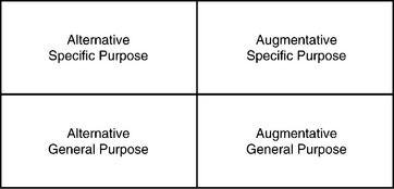
Figure 14-1 Assistive technologies for manipulation can be categorized in two dimensions: general purpose versus specific and alternative versus augmentative.
LOW-TECHNOLOGY AIDS FOR MANIPULATION
Chapter 1 defines low-technology aids as inexpensive, simple to make, and easy to obtain. Many manipulative aids fall into the low-technology category. We group these aids into general- and special-purpose devices. Within special-purpose devices, we categorize devices according to the major performance areas of the human activity–assistive technology (HAAT) model: self-care, work or school, and play or leisure. All the examples used in this section are available from mail-order catalogs.* Many of these devices are also available at drugstores and other local sources.
General-Purpose Aids
To be classified as general purpose, a manipulation aid must serve more than one need. Three general-purpose aids are discussed: mouthsticks, head pointers, and reachers. The first two of these are often used as control enhancers in conjunction with control interfaces. In Chapter 7, head pointers and mouthsticks are discussed in detail, including their use as control enhancers for activating control interfaces. Both mouthsticks and head pointers are also used for direct manipulation. Turning pages is often accomplished with a mouthstick or head pointer used in conjunction with a book or magazine mounted on a simple stand. A ballpoint pen tip or a pencil can also be attached to a mouthstick for writing. Additional attachments include a pincher that is opened or closed by tongue action and a suction cup end that can be used to grip objects (e.g., a page) by sucking on the end of the mouthstick. Many tasks require sliding objects (e.g., paper, pens) around on a desk or table. Both mouthsticks and head pointers can be used for this task. Mouthsticks or head pointers can also be used for such functions as dialing a telephone, typing, and turning lights on and off.
Many individuals need to extend their physical range. Often the need for extended range is a result of being seated in a wheelchair and wanting to reach an object on a counter or in a cabinet. In other cases it is a need to reach an object on the floor when bending is difficult or stability is poor. In all these cases, reachers can be useful. As shown in Figure 14-2, a reacher consists of a handle grip that is used to control the jaws of the reacher to grasp an object. The grasp required to activate the grip may be of several types: squeeze with the whole hand, pistol grip with all the fingers, or trigger with the index finger. Overall length varies from 24 to 36 inches, and some models fold for ease of carrying. The gripper portion of the reacher may be circular for ease of gripping cans or pincherlike for picking up smaller objects. Rubber or other nonslip materials are often used for reacher grippers. Reachers can be used to manipulate many objects, including food (e.g., cans, packages), cooking utensils (e.g., pans, pots, plates, dishes), office objects (e.g., paper, books, magazines), and recreational or leisure objects (e.g., books, tapes, CDs).
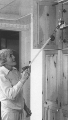
Figure 14-2 Mechanical reachers are general purpose devices. (Courtesy TASH, Ajax, Ontario, Canada.)
Chen et al (1998) conducted a study of the effectiveness of reachers in meeting the needs of a population of older (over 60 years) subjects. The characteristics found to be most important were adjustable length, one-handed use, a locking system for the grip to hold objects, support for the forearm, light weight, and a lever trigger action in the grip. Chen et al (1998) also list 38 tasks for which their population uses reachers. These include food preparation, self-care, appliance control, and gardening. Chen et al (1998) also discuss the relative ease of use of reachers for a variety of tasks.
Special-Purpose Aids
Because special-purpose, low-tech aids are designed for one or two tasks only, they serve those tasks very well. However, because they are so specialized, it may be necessary to have several of these available to meet the demands of self-care, work, and leisure.
Most special-purpose adaptations of products involve one of four things: (1) lengthening a handle or reducing the reach required, (2) modifying the handle of a utensil for easier grasping or manipulation, (3) converting two-handed tasks to one-handed ones, and (4) amplifying the force that a consumer can generate with her hands. A variety of modified handles are shown in Figure 14-3. These include enlarged grips for easier grasping, cuffs that hold a utensil and circle the fingers, angled handles for ease of scooping (for people with limited wrist movement), swivel handles that allow the end to be oriented differently for different positions in space (e.g., on a table or near the mouth), and handles requiring limited grasp (often called “quad handles”).
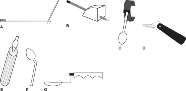
Figure 14-3 Types of handles used on low-tech manipulative aids. A, Brush with extended handle. B, Enlarged grip for pencil or pen. C, Spoon with cuff. D, Key holder with quad grip. E, Buttoner with enlarged handle. F, Spoon with bent handle for scooping. G, Spoon with swivel handle.
Self-Care.
Self-care includes aids for assistance in several areas: food consumption, food preparation, dressing, and hygiene. Examples of food preparation adaptations include one-handed holders for can and jar opening, brushes with suction cups for one-handed scrubbing of vegetables, bowls with suction cup bottoms for stability while stirring with one hand, bowl and pan holders (some of which tilt for pouring), and cutting boards that stabilize food during cutting. Modified handles are available for knives and serving spoons, as well as for other utensils.
Food consumption aids include a variety of utensils with modified handles (knives, forks, spoons, and combinations called “sporks”). Modifications to plates include suction cups for stability, enlarged rims that make it easier to scoop food onto a utensil, and removable rims that attach to any plate. Drinking aids include cups with caps and “sipper” lids through which fluid can be sucked; nose cutouts that allow drinking to occur without tipping the head back; double-handled cups for two-handed use; and cups modified at the bottom with a quad grasp to allow lifting and tipping with limited hand function.
Dressing aids designed to compensate for poor fine motor control include adapted button hooks for single-handed buttoning and zipper pulls. These are available with enlarged, suction, and quad grip handles. For limited reach, there are aids for pulling on socks and pantyhose, long-handled shoe horn, and trouser pulls. A variety of dressing aids are shown in Figure 14-4.
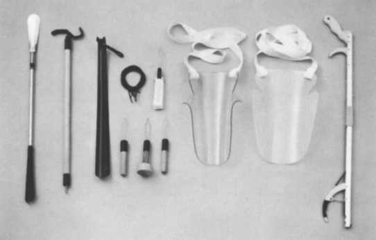
Figure 14-4 A variety of dressing aids. Left to right: Long-handled shoehorn, dressing stick, plastic shoehorn, elastic shoe laces, button hooks (4), stocking aids (2), and reacher. (Courtesy TASH, Ajax, Ontario, Canada.)
Areas of hygiene that can be aided by special-purpose devices include hair combing and brushing, tooth brushing, shaving, bathing, and toileting. Hairbrushes and combs may have any or all of the following adaptations: modified handles of all types, extended handle lengths, and angled ends (where the comb or brush attaches). Modified toothbrushes have enlarged, quad, and offset handles. Toothpaste and shaving cream containers can be adapted with a simple device that allows one-handed dispensing of the product. For shaving, there are holders with adapted handles for both electric and manual razors. For bathing, there are long-handled sponges, curved handle brushes for washing the back, and holders for sponges or washcloths that accommodate limited grasping ability.
Other self-care items are intended for use in the home. For example, there are gripping cuffs that are used with brooms and mops, extended handles on household items such as dustpans and dusters, and key holders.
Work and School.
Throughout this book we have described assistive technologies that aid consumers in accomplishing work- and school-related tasks (e.g., computers, augmentative communication devices). This section discusses low-tech aids that specifically help work and school in the areas of writing and reading.
Handwriting is a major need in work and school environments. Special-purpose manipulative aids that assist handwriting focus on one of two problems: holding the pen or pencil and holding the paper. Some consumers lack the ability to grip a standard pen or pencil. Low-tech approaches to this problem include modified grippers that attach to the hand and clamp to the pen or pencil; wire, wooden, or plastic holders that support the pen or pencil off the paper and allow it to slide across the paper; weighted pens (with variable amounts of weight) that help reduce problems associated with tremor; and pens with enlarged bodies to make them easier to grasp. There are several different designs for holding paper in place for one-handed writing. Generally the paper is held to a plate using either clips or a magnet (in this case the plate is steel). Desks can also be modified using a rotating “lazy Susan” device that rotates to bring items within reach. File folders are often modified for easier grasping by putting hooks or loops on them. The loop or hook protrudes above the folder so that it can be grasped more easily. High-tech aids for writing are discussed in Chapter 11, and additional work-related assistive technology applications are described in Chapter 16.
There are also low-tech reading aids. Book holders provide support for the reading material so that the consumer does not have to hold it. Page turning is done either by hand or with a head pointer or a mouthstick. The next section discusses electrically powered page turners that aid reading.
Play and Leisure.
As with other types of manipulative aids, lack of grasping ability in recreational or leisure aids is generally accommodated for by altering the type of handle. Recreation and leisure examples include cameras with modified shutter release, modified grip scissors, modified handles on garden tools, and modified grasping cuffs for pool cues, racquets, or paddles. A person with limited manipulation strength can fly a kite by adding special wrist or hand cuffs for holding the string. Pinball machines can be adapted with larger buttons to allow control by children and adults with disabilities (for example, http://www.rehabilitystores.com/). The paddles can be controlled by puff-and-sip or any other switches. This makes it possible for a consumer to compete in a fast-paced, interesting game. Computer access methods that were described in Chapter 7 enable an individual to play computer games in the same way they provide access to educational materials.
One example of a holder is a gooseneck arm attached at one end to a table clamp. At the other end is a bracket that holds an embroidery frame. Using this device, an individual can embroider, crochet, or mend with only one hand. Other examples of devices designed for one-handed assistance are playing card holders, knitting needle holders, and card shufflers. For individuals with limited two-hand function, there are handheld playing card holders.
Devices that aid lack of reaching ability include a mobile bridge for holding the end of a pool cue off the table (a small bracket with wheels to allow positioning of the pool cue) and ramps for use while bowling (the ball is placed at the top of the ramp and the user releases it after aiming the ramp toward the pins). Lange (1998) describes a variety of options for reading when manipulation of the material is difficult.
SPECIAL-PURPOSE ELECTROMECHANICAL AIDS FOR MANIPULATION
There are two primary manipulative tasks for which electromechanical devices have been specifically designed and for which there are commercially available products: (1) feeding and (2) page turning. These special-purpose alternative manipulation devices are discussed in this section.
Electrically Powered Feeders
One area of human activity in which independence is highly desirable is eating. Anyone who has been unable to feed himself or herself (even for a brief period) knows the frustration of looking at one type of food on the plate and being fed another (e.g., expecting peas and getting potatoes). Being fed by another person can also create a feeling of dependency, and lack of independence in eating is often equated with childlike behavior. None of these stereotypes is accurate, and most persons who are fed by an attendant maintain control over the situation through direction of the attendant’s actions. Nevertheless, many people would prefer to feed themselves if it were possible. Electromechanical feeders make this an option even for individuals who have very little motor control.
Use of an automatic feeder requires that the individual be able to control two separate functions. The first of these is location of the particular type of food that is to be eaten, and the second is picking up the food and moving it to mouth level. Currently available feeders require that the human operator be able to take food off a spoon, chew it, and swallow it safely. These requirements eliminate a large number of persons, but there are many who only lack the ability to pick up the food and get it to their mouths. It is this group for whom feeders are most beneficial.
Generic electromechanical feeders are shown in Figure 14-5. The first task of feeders, that of locating the desired type of food, is typically accomplished by placing the plate on a turntable whose rotation is under the control of the user. The user is able to stop the rotation when the desired food is properly positioned. The second action, moving the food to mouth level, is typically accomplished by a spoon attached to an arm whose height above the plate is variable. Two types of arms are used: (1) two-piece articulating and (2) telescoping. The articulating arm is capable of carrying greater weights and can position the spoon in more locations. The telescoping arm collapses into a smaller stored length and can be easier for transportation. Picking up the food is a process of scooping the food onto the spoon. One of two approaches can be used: moving the spoon against a fixed stop or moving a pusher against a fixed spoon (see Figure 14-5). For either of these approaches, both the spoon and the plate can be removed and washed with other dishes.
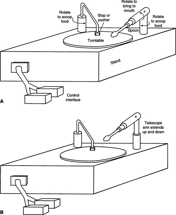
Figure 14-5 Two types of electromechanical feeders. A, The spoon is attached to a lever arm that is moved to mouth level. B, The spoon is attached to a telescoping arm that moves it to mouth level.
To control the feeder, the user must activate either one or two switches. The two-switch approach typically has one switch for plate rotation and one to scrape the food onto the spoon and raise and lower the spoon. In the one-switch version, activating the switch one time causes the plate to rotate; a second activation causes a complete cycle of pushing food onto the spoon and raising it to mouth level. Any single or dual switch described in Chapter 7 can be used.
The most commonly available feeder is the Winsford Feeder (Winsford Products, Pennington, NJ, available from Sammons Preston Rolyan, a Patterson Medical Company, www.sammonspreston.com), which is also marketed by several mail order equipment companies. This feeder has rechargeable batteries that are used to power it at many different settings. It has an adjustable height base that can accommodate varying spoon height requirements. A two-switch mode of operation is used, with one switch rotating the plate and the other scooping the food onto the spoon and elevating it to mouth level. A chin-activated dual switch is mounted on a long, solid wire. When it is pushed in one direction, plate rotation occurs, and when it is pushed in the opposite direction, food is pushed onto the spoon and elevated to mouth level. A two-position rocking switch is also commonly used with the Winsford Feeder. Other dual switches or two single switches may be adapted to work with this feeder. There is also a carrying case available for transportation of the feeder.
Another commercially available feeder is the Beeson Automaddak Feeder (Maddak, Inc., Pequannock, N.J., http://service.maddak.com). This feeder is powered by a 110-volt line. It is operated by two switches, one for plate rotation and the other for spoon control. In contrast to the Winsford Feeder, each switch must be held down to continue action; that is, the spoon elevation stops if the spoon switch is released. The Electric Self-Feeder (Sammons Preston Rolyan, a Patterson Medical Company, www.sammonspreston.com) is another powered feeder. This feeder uses a chin switch to activate the motorized pusher that fills the spoon. After the spoon is full, it automatically moves to the mouth. The plate is rotated to bring the desired food into range of the spoon.
A robotic system specially designed for feeding is the Handy 1 (Topping, 1996). The Handy 1 uses a series of seven columns or compartments on a tray. When it is activated, the Handy 1 scans through the tray, illuminating a light behind each column in succession. The user activates a single switch to choose the column, and the food in that column is bought to the mouth. An eighth light allows the user to access a cup for drinking at any time during the meal. More than 100 individuals have benefited from the use of the Handy 1 on a regular basis (Topping, 1996).
Harwin, Rahman, and Foulds (1995) compared the Handy 1 and the Winsford Feeder. They point out that the Winsford Feeder has only two degrees of freedom, whereas the Handy 1 has five. This increases the flexibility of the Handy 1 in dealing with the task of feeding, and it also allows it to perform some other tasks of daily living (e.g., self-care). The interface requirements of the Handy 1 are also more flexible than those for the Winsford Feeder. For example, the location where the food is to be transferred into the person’s mouth can be changed. However, the Winsford Feeder is considerably less expensive than the Handy 1. This illustrates the tradeoff between flexibility and complexity (and hence cost) discussed earlier.
All these feeders require that the food be prepared in bite-sized portions for the user. It is also sometimes difficult to eat certain foods such as soups and those composed of small pieces (e.g., rice, peas). Because of the necessity for assistance from a human aide or attendant, independence is reduced. However, the user is able to complete the eating activity independently, and this can save attendant time (and cost) and improve the user’s sense of independence and control. Recall that the HAAT model discussed in Chapter 2 includes both an activity (in this case eating) and a context (defining the environment where the activity takes place). One of the most important considerations of the context is whether the environment will support the use of a feeding device. An individual may choose to use the device in one setting but not in another. For example, in the home situation where the physical and social context supports this type of technology, feeding devices might be acceptable. However, in a restaurant situation, they may draw unwanted attention to the user.
The primary safety considerations with feeders are mechanical injury from the spoon hitting the face and embarrassment caused by food falling off the spoon or plate. These devices can be messy to use and difficult to transport, and this may cause some people to restrict their use to home and to rely on a human attendant in the community.
Although they serve a restricted need and can be used by only a specific segment of persons with disabilities, electrically powered feeders can play an important role in increasing independence for persons whose motor limitations prevent them from using standard eating utensils.
Electrically Powered Page Turners
Access to books, magazines, and other reading material is important for the acquisition of information for school, work, or leisure. There are many individuals with disabilities who are able to read but who cannot physically manipulate the pages of the reading material. There are several approaches that can be used to assist these individuals. A book holder and mouthstick (see the section on low-tech aids in this chapter) allow independence in page turning for some persons. The major limitation of this approach is the requirement that the book be set up by an aide and properly positioned for both visual and physical access. This method also requires a high degree of head control and the ability to hold a mouthstick. A mechanical head pointer eliminates the last requirement, but there are still limitations of access.
Talking books, such as those made available for the blind, can also provide an alternative to physically manipulating pages. These are discussed in Chapter 8. By using a simple environmental control unit, a person with physical limitations can control the tape recorder and obtain access to the talking book at his or her own speed. Another approach is the use of books on computer disks. These can be loaded into a word processor, and the person needing access can use standard computer adaptations to turn the pages, scan through the material, find key words, and so on. This approach is also used by persons who have low vision or are blind, and it is discussed in Chapter 8. Both talking books and computer-based reading have the limitation that not all reading material is available in these formats.
An alternative to all these methods is the use of a human attendant to turn the pages. Because the turning of a page occurs every few minutes, this is not practical for any large amount of reading. The limitations in all these approaches have led to the development of electrically powered page turners.
From a manipulative point of view, page turning requires two primary actions: (1) separating the page to be turned from the other pages and (2) physically moving the page from one side to the other (forward or backward). Additional useful but not essential features include scanning a number of pages, turning to a specific page, and locating a bookmark and turning to that page. Currently available page turners use one of two methods to accomplish the first task of separating pages. Some devices use a vacuum pump that sucks the first page up and holds it away from the remaining pages. Other devices use a sticky roller that is placed on top of the page. When it rotates, the roller causes one page to be separated from the others. The roller may use putty, rubber gum (like a pencil eraser), or double-sided tape. This function is the most difficult for page turners, and its success for any page turner is a major indicator of the quality of the unit. Because reading materials differ widely in size, binding (e.g., uniform, spiral, loose leaf), and paper types (e.g., rough, slick, newsprint), it is important to evaluate any individual page turner with reading materials that vary in size, paper type, and binding style.
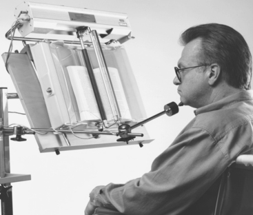
Once the page to be turned is successfully isolated, the page turner must move it to the opposite side of the book or magazine. The Gewa page turner (in North America, distributed by Zygo Industries, Portland, Ore., http://www.zygo-usa.com/) (Figure 14-6) uses a rotating roller to separate pages from each other and then moves the entire roller from one side of the book or magazine to the other after the page has been separated. The standard control for the Gewa is a four-direction joystick. Two joystick directions cause roller rotation either clockwise or counterclockwise, and the other two cause the roller to move forward or backward. Any other four-switch control interface can also be used. An additional accessory for the Gewa page turner is a scanning selection method in which a single switch is used to select one of the four control functions as they are presented in sequence. The display of functions consists of small LED indicators, each labeled function corresponding to one joystick direction.
Other page turners have different mechanisms. The Touch Turner (Touch Turner Company, Everett, Wash., www.touchturner.com/) uses a rubber-coated wheel to separate the pages, and then a rotating semicircular disk pushes the separated page from one side to the other. As the disk rotates, the page is moved forward or backward, depending on the direction of rotation of the disk. The Touch Turner has both one-direction and two-direction models for standard books and a special model for paperback books and magazines. Vacuum-based systems often move the vacuum unit from side to side.
ELECTRONIC AIDS TO DAILY LIVING
Many objects that need to be manipulated are electrically powered devices such as appliances (e.g., television, room lights, fans, kitchen appliances such as blenders or food processors) and others that can be modified by adding electrically powered control to them (e.g., door openers, drapery controls). The majority of these electrical appliances and controls are powered from standard house wiring (110-volt AC in North America). Figure 14-7 shows the major parts of an electronic aid to daily living (EADL). The user interacts with the EADL through a control interface (see Chapter 7). Feedback to the user is provided through a display that reflects the action being controlled (e.g., which appliance is to be activated, status of the system). The control interface and user display constitute the human/technology interface. They are connected to the rest of the system and to each other by a block labeled selection method. Likewise, the appliances to be controlled are connected to the selection method through an output distribution block. The selection method and output distribution functions together make up the processor. In some cases the human/technology interface and the selection method are provided through an augmentative and alternative communication (AAC) device (see Chapter 11) or a computer (see Chapter 7) by a serial input, which can reduce the number of devices and also provides an identical user interface for both AAC and EADL functions. Some AAC devices also include the output distribution component. This component is connected to either a remote (wireless) linkage or a hard-wired connection or both; it produces an activity output by turning on and controlling the appliances.
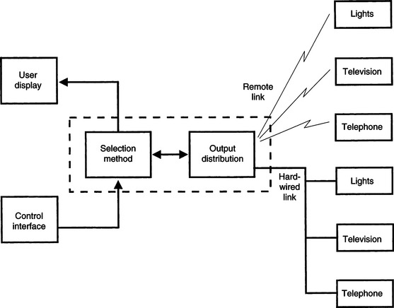
Figure 14-7 The major parts of an EADL. The control interface and user display constitute the human/technology interface. The components within the dotted box are the processor. The appliances listed on the right side of the figure are the activity output.
Some devices or appliances require on-off control. Normally this is achieved by a switch that is pressed to activate the device. An example of this type of control is that used in many remote garage door openers, which require a single press and release to start the door opener. The process then proceeds automatically until the door is open. This type of appliance control device is often used by persons with disabilities to open other doors (e.g., house or apartment). This may require either that the switch on the garage door opener be adapted or that the entire function be incorporated into the EADL.
There are two switch outputs available on most EADLs: (1) momentary and (2) latched. A momentary switch closure is active only as long as the switch is pressed. In the case of the EADL, this output remains active only as long as the control interface is activated (e.g., a switch is pressed). The momentary output mode is useful for continuous functions such as closing draperies. The output can be sustained as long as the person desires it to be (e.g., to open drapes half way). In the latched mode a switch closure is turned on by the first activation and off by the next activation, and it toggles between these two states with each activation. This can be useful when turning on an appliance such as a light or radio.
Selection Methods
Chapter 7 defines several selection methods used for control of assistive technology devices. These include direct selection, scanning, directed scanning, and coded access. Each of these can be used with EADLs. Direct selection occurs when the user of the system can choose any output directly. For example, an EADL for controlling a room light, a fan, and a radio on-off control may have one control interface (possibly a key on a small keyboard or speech recognition) for each of the three functions (Figure 14-8). If the same three-unit system is to be operated by scanning access, then the keyboard can be replaced by a scanning panel and each of the three items to be controlled has a corresponding light. When the light of the device to be activated comes on, the user activates a control interface to select that item. Finally, a code such as Morse code (see Chapter 7) can be used for one of the four output devices. The user enters a series of dots and dashes corresponding to the numerical code required to activate the desired appliance. Each of these selection systems is used in current EADLs, and some EADLs have multiple options available. Specific selection methods are discussed in the remainder of this section. Choice of a control interface for use with an EADL is based on the considerations presented in Chapter 7. Some control interfaces (e.g., speech recognition,** single switch) are commonly used with EADLs.
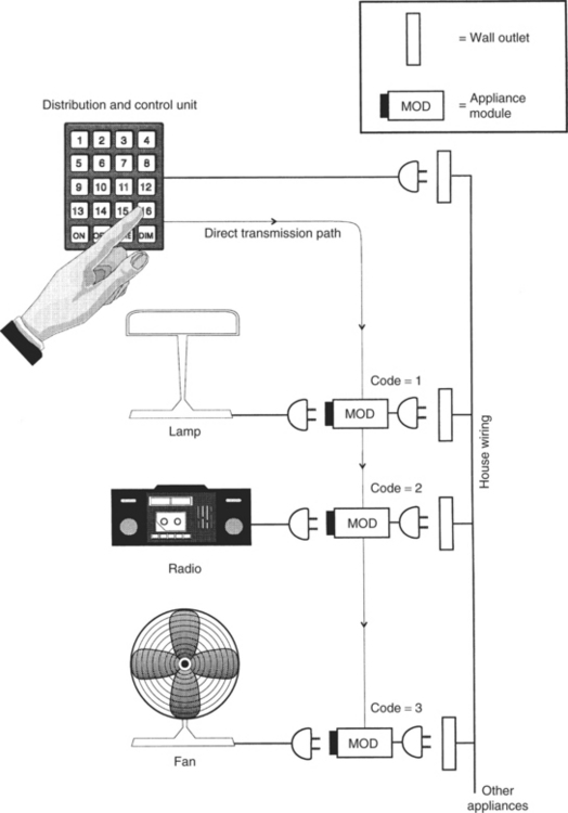
Figure 14-8 A direct-selection EADL. Each appliance has a numerical code, and the keypad is used to select the appropriate module. Control functions such as ON, OFF, and DIM are also activated by pressing the proper key on the keypad. This figure also illustrates the use of house wiring for distribution of the control signals to the appliance modules.
Control Functions Implemented by Electronic Aids to Daily Living
Chapter 7 defines the input domain for the control interface as either discrete or continuous. The most common type used in EADLs is discrete control, in which a device is either turned on or off or set to a specific value by activation of the EADL. Examples of on/off control include lights, television, or radio controls and starting or stopping a blender. Other EADL applications require setting a value. For example, a telephone dialer may have several stored numbers that may be selected. Each number is a discrete entry, and its selection produces a different result. Television channel selection is another example of discrete control. The other type of control function used in EADLs is continuous control, which results in successively greater or smaller degrees of output. Examples of EADL continuous control are opening and closing draperies, controlling volume on a television or radio, and dimming or brightening lights.
Transmission Methods
All EADL systems must transmit a signal to the appliance to be controlled. There are several methods used for this transmission. Although it is theoretically possible to connect all the appliances to be controlled directly to the rest of the EADL by wires, this method is not practical. Direct wiring requires that the controlled devices be physically close together or necessitates the installation of special wiring just for the EADL. More cost-effective and practical methods use some form of remote control. We use the term remote control to mean the absence of a physical attachment among the various components shown in Figure 14-7. In general, the link between the output distribution and the devices to be controlled is remote. However, it is also possible to have remote links between the control interface and the processor.
House Wiring-X10.
One way to interconnect appliances and the output distribution function is to use the house AC wiring as a communication channel. Digital control signals are transmitted over the house wiring from the distribution control device to individual appliance modules, which are plugged into the standard electrical outlet (see Ciarcia, 1980, for a description of the operational details of these units). Figure 14-8 shows how this approach works. The distribution and control unit is also plugged into a wall outlet. This unit has a transmitter that sends out two codes over the house wiring. The first code identifies the device to be controlled, and the second selects the function to be performed (e.g., turn on or off, dim or brighten a light). Each appliance to be controlled is plugged into a module, which is then plugged into the wall. Each module contains a receiver that can interpret the codes sent out by the distribution and control unit. Most commercial systems have selector switches on the appliance modules to allow them to be set for a code from 0 to 15. In addition, both the distribution and control unit and the appliance modules can have one of 16 different “house” codes that allow two or more such systems to operate on the same wiring system. The combination of house codes and device numbers yields 256 possible controlled devices (16 × 16). Although this may seem like a large number, it can be useful to have more than a few choices, especially when the control is by computer-based software rather than manual selection of keys on the distribution and control unit. This type of appliance control was designed for use by the general population, and consequently, it is common and inexpensive. Devices are available at many consumer electronic stores (for example, the X-10 Powerhouse System, Northvale, N.J., www.x10.com). This type of device can become a relatively complete EADL for individuals who are able to press the buttons on the control unit. However, only binary control functions are available, (i.e., on/off) and such functions as channel selection (quantitative) or volume control (discrete) require more specialized systems.
The major advantage of house wiring transmission is the lack of installation costs because existing wiring is used (Mills, 1987). Disadvantages include (1) the lack of privacy, (2) possible interference between systems on the same electrical power system (e.g., in an apartment building), (3) the inability to transmit when multiple circuits are used for the wiring system, and (4) the lack of portability. Multiple circuits are often used in house and commercial wiring. Each circuit has a separate circuit breaker, and they are physically separate from each other, which means that a module connected to one circuit does not receive the control signals from a transmitter connected to a different circuit.
Ultrasound Transmission.
A second type of transmission used between the control and distribution unit and the appliances to be controlled is ultrasonic transmission. This type of transmission uses sound waves that are too high in frequency to be heard by the human ear. In general, that is any signal more than 20,000 Hz, but in practice signals of approximately 40,000 Hz are used. These signals are transmitted through the air to a receiver located up to several hundred feet from the transmitter. Because ultrasound waves are mechanical energy, they can be blocked by solid objects (including human tissue), and it is important to have a clear path between the transmitter and the receiver. Ultrasonic transmission devices (for example, ElectraLink, TASH, Ajax, Ontario, Canada, http://www.tashinc.com) often consist of a transmitter unit, which is either handheld or mounted on a wheelchair, and a set of receivers, one for each appliance to be controlled (Figure 14-9). A latched mode is typically used. Various selection methods, including scanning and coded access, are available for these devices. The principle of operation is slightly different from that of house wiring–based systems. Each receiver has a code, and the transmitter sends a signal that corresponds to this code. When the transmitted code is received, the receiver is latched, which turns the appliance either on or off, depending on its state when the signal is received. Each appliance must have its own code, and most ultrasonic devices have a limited number of channels (generally four or eight).
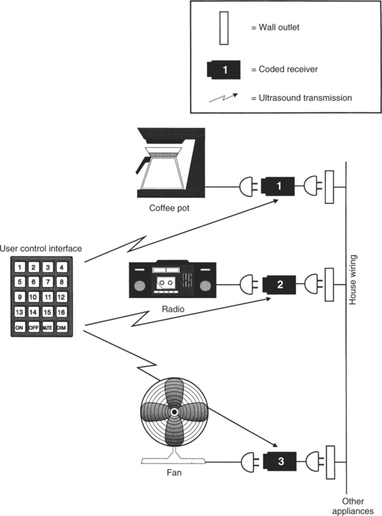
Figure 14-9 An EADL system using ultrasound transmission to discrete modules. Each module receives its signal directly from the transmitter.
Ultrasonic transmission is also used for some remote television controls. In this application, transmission of various codes is used for all basic television functions, such as on/off, channel change, volume control, and picture adjustments. Another use of ultrasound transmission is illustrated in Figure 14-10. In this case the coupling between the control interface and the distribution and control unit is by ultrasonic transmission. This remote coupling enables the user to be more mobile than when the control interface is hard wired to the distribution and control unit.
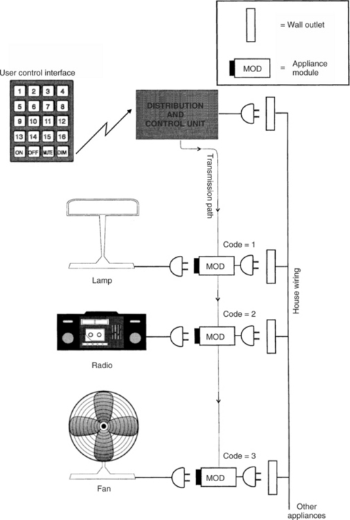
Figure 14-10 An EADL that uses ultrasound or IR transmission from the control interface to the distribution and control unit. As in Figure 14-8, house wiring is used for transmission from the distribution and control unit to the appliance modules.
The major advantage of ultrasonic transmission is that it is highly portable because it is easy to unplug the receiver modules and move them to a new location. The major disadvantages are the necessity to have the transmitter and receiver in the same room and to avoid obstacles between the transmitter and receiver that might block the signal.
Infrared Transmission.
Another mode is based on the use of invisible infrared (IR) transmission as the medium. This method is the most common in the control of home electronics (e.g., television set, cable television, DVD/CD player). IR remote controls are used for binary (latched and momentary), discrete, continuous, and quantitative types of control. The DVD functions of FAST FORWARD, SEARCH, and so on can also be controlled with an IR remote controller. Generally each remote device has a set of unique codes, and a remote unit manufactured by one company cannot be used with a system manufactured by someone else, which means that several remote controllers may be necessary to manage TV, cable, and other devices, unless a “universal remote” is programmed to control all these appliances.
IR remote control is also used in EADLs. The remote link between the control interface and the distribution and control unit in Figure 14-10 is often implemented by using IR instead of ultrasound. In this case the control scheme is the same as that described above for other IR remote controls. Sometimes the link between the control and distribution unit and the remote appliances is also implemented with IR transmission. The engineering, design, and construction of IR controllers are described by Ciarcia (1987b).
The major advantages of the IR devices are no installation costs (compared with hard wiring) and ease of portability. A major disadvantage is that the signal can be blocked by many materials, so a direct line of sight between the transmitter and receiver is required (Mills, 1987), which means that the transmitter and receiver must be in the same room. Because the receiver must be connected to the controlled appliances (possibly through the house wiring), the line-of-sight requirement limits the range of application (e.g., outside, inside, different rooms). Because the IR devices are light sensitive, they often do not work well in bright sunlight. Recall that the HAAT model includes a consideration of the physical context (see Chapter 2, Figure 2-4) in which a given activity is taking place. In this case the EADL is typically used in an interior location where light, heat, and sound can be controlled. However, interference from other appliances or interference caused by transmission from the EADL can affect the performance of these systems.
Radio Frequency Transmission.
A final transmission approach is the use of radio frequency (RF) waves as the link between the distribution and control unit and the control interface, the controlled appliances, or both. The most common examples of this type of remote control are garage door openers and portable telephones. The term RF transmission is used because the signals are in the same range as broadcast FM radio. Radio frequency transmission is used as the link between the control interface and the processor.
The major advantage of RF transmission is that it is not blocked by common household materials (it can be blocked by metal that is connected to the ground), and transmission can be over a relatively long distance throughout a house and yard. Because it is less restricted, it has the major disadvantages of interference and lack of privacy (Mills, 1987). The interference problem is generally approached by reducing the distance between the transmitter and the receiver and by having several transmission channels available. The user can switch between channels (or the device will automatically scan) to find the strongest signal. Privacy is generally addressed by allowing the user to select a transmission code (often with a bank of small switches) and then matching the transmitter and receiver codes.
One form of wireless technology is known as ZigBee. In addition to providing control that has all the advantages of RF transmission, Zigbee has low power consumption (meaning longer battery life) and long range of operation (range enough to control the whole home from anywhere inside it, not just the immediate room). Zigbee is ideally suited for low data rate applications (i.e., applications where the amount of information to be transmitted is small as in simple on-off controls) such as EADLs (Bessell et al, 2006). There are specifications for Zigbee applications that are made available through the ZigBee Alliance (http://www.zigbee.org/en/about/). The goal of the alliance is to build wireless intelligence and capabilities into everyday devices. This will lead to companies having a standards-based wireless platform optimized for the unique needs of remote monitoring and control applications that includes simplicity, reliability, low cost, and low power (Kinney, 2006).
Trainable or Programmable Devices
Remote devices that use ultrasound, IR, or RF typically are designed for operation with only one appliance (e.g., TV, VCR). If an individual owns several remotely controlled devices, this can lead to “controller clutter,” with a separate control required for each device. To reduce this problem, several manufacturers produce remote control units that can be adapted to work with any appliance. Some of these are called trainable controllers. These devices operate by storing the control code for any specific appliance function (e.g., on/off). As shown in Figure 14-11, A, the storage is often accomplished by pointing the trainable controller at the controller for the specific appliance and sending the specific function code (TV ON in Figure 14-11). The trainable device then stores this code for future use. When the stored code is sent to the appliance, it is received and used as if it had been sent by the appliance’s own controller. This process is illustrated in Figure 14-11, B. In this manner, all the functions of the individual appliance controllers can be stored in one master controller and the user need only activate this one device. Most of these controllers have two modes: train and operate. Figure 14-12 shows a programmable EADL unit mounted to a wheelchair and used for controlling appliances such as the television.
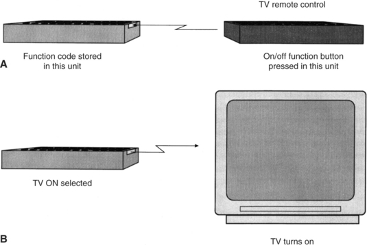
Figure 14-11 A trainable IR controller. The trainable or programmable controller is shown on the left. A, Training is accomplished by aiming the device-specific control at the trainable controller and pressing the desired button (in this case, TV ON). B, The trained unit can then be used with the appliance to accomplish the desired function.
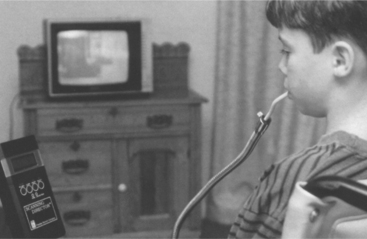
Figure 14-12 A trainable infrared EADL with scanning access. The EADL is shown mounted to a wheelchair. It is positioned so there is a line-of-sight link to the television for use of IR control. (Courtesy APT Technology, Inc., DU-IT CSG, Inc., Shreve, Ohio.)
Some controllers have codes for many appliances permanently stored in them. The user selects a code corresponding to his appliance (e.g., a television set made by a specific manufacturer). Ciarcia (1987a) describes the technical operation of trainable devices for IR controllers. These devices, like the individual appliance units, are designed using special-purpose microcomputers. In the training mode the EADL device is aimed at the individual appliance, the function to be stored is pressed on the individual control, and the code is stored. This process is repeated for all functions and for all individual controllers. These devices are relatively small, lightweight, and battery powered, and they can be hand carried or mounted to a wheelchair.
An alternative approach is based on the storage, in the controller, of codes that are appropriate to a range of appliances. The user selects her appliance and looks up the controller code in a table. Once this code is entered into the controller, it is able to control the appliance. We refer to these as programmable controllers.
Trainable or programmable controllers designed for the general home electronics market can be of benefit to persons with disabilities who are able to press the small keys associated with these devices. For those persons who cannot use standard controllers, there are specially adapted trainable or programmable units that provide both direct selection and scanning selection.† Control interfaces include expanded keyboards or a built-in keyboard or single switches for scanning access. In the latter case, one of two methods is typically used: (1) small lights that are located next to each button are sequentially illuminated or (2) alphanumerical labels or numerical codes for each function are sequentially displayed. For each of these approaches, the user presses the switch when the desired choice is presented.
As shown in Figure 14-11, most of the trainable or programmable EADL devices can be interfaced to other electronic devices (e.g., AAC devices, computers, power wheelchair controllers) through a serial port. To control the EADL, a code must be sent from the communication device or computer to the controller, and all specific functions and separate appliance codes must be stored in the communication device or computer. Several manufacturers include control software for EADL in their communication software programs (see Chapter 11). When the EADL is controlled by a computer or communication device, the software program generates the control signals and sends them through the serial port to the EADL.
To facilitate the control of appliances, cell phones, and other electronic devices the concept of a universal remote has been developed (Zimmerman et al, 2004). The universal remote standard is intended to allow users (including EADL users) to interact with networked devices and services in their environments. The universal nature of the controller specification means that all devices meeting the standard will be able to interact because they will follow predefined protocols rather than being unique to each manufacturer. The universal remote standard provides a versatile user interface description for devices and services, called a “user interface socket” to which any universal remote console (URC) can connect. Each URC can electronically “discover” remote devices or services in its range and then access and control them. Examples of services include cell phones and wireless computer networks. Devices could be any of these described for EADL control (e.g., television, CD/DVD players, standard telephones). A major advantage is that, with only one user interface description, diverse URC technologies can be supported, including connection through desktop and laptop computers and personal digital assistants.
Telephone Control
Persons with physical disabilities of the upper extremities often have difficulty in carrying out the tasks associated with telephone use. These include lifting the handset, dialing, holding the handset while talking, and replacing the handset to its cradle. Telephones differ greatly in design (e.g., portable, speaker, rotary or touch-tone dial), but all require that the listed tasks be performed. As in many other areas of assistive technology, there are a variety of ways to accomplish the same tasks. Mouthsticks or head pointers (see the section on low-tech aids earlier in this chapter) can be used to press a button to open a line on a speaker phone (equivalent to lifting the hand set), dial by pressing buttons, and hang up at the end of a conversation. There are also simple holders that position a handset for hands-free operation and mechanical switches with long handles that control the switch hook for answering a call or hanging up after a call. Finally, telephone companies provide operator-assisted calling for persons with disabilities, so it is only necessary to press 0 for an operator, who then dials the call for the consumer. Our emphasis in this section, however, is on electronic telephone access systems, which are often integrated into EADLs.
Because modern telephones are actually sophisticated electronic devices, automation by use of electronic telephone controllers is relatively easy, and there are a variety of commercial products available to accomplish telephone access for persons with disabilities (for example, Relax 3 and Imperium, TASH, Ajax, Ontario, Canada, www.tashinc.com; Gewa IR Controlled Telephone, Zygo Industries, Portland, Ore., www.zygo-usa.com). Many of the general-purpose EADLs have telephone functions built in (for example, Ezra, KY Enterprises, Belgrade, Montana, www.quadcontrol.com; EZ Control, Regenesis, North Vancouver, B.C., Canada; Simplicity Switch, Quartet Technology, Inc., Tyngsboro, Mass., www.qtiusa.com; Imperium, Sicare Pilot, Relax 3 TASH, TASH, Ajax, Ontario, Canada, www.tashinc.com). The functional components of a telephone controller are shown in Figure 14-13. Individual devices may group these components differently. Telephone controllers for a person with disabilities are built around standard telephone electronics. In some cases the controller is connected into the standard telephone, whereas in others the telephone is bypassed and the controller plugs directly into the telephone line. In any case, several of the important functions are common to consumer telephones. For example, the use of stored numbers (automatic dialing) and redial can save a great deal of time when the user must use scanning to select numbers. Another useful feature of currently available adapted telephones is that the user can answer electronically rather than by physically picking up the handset. This is done as an additional choice on a scanning menu or a direct selection on an EADL telephone control panel.
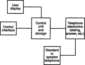
Figure 14-13 Functional components of an automatic telephone dialer. The control interface and user display constitute the human/technology interface, the control unit and storage and telephone electronics are the processor, and the telephone constitutes the activity output.
Other parts of the telephone controller shown in Figure 14-13 are necessary only for persons who require single-switch access to the system (e.g., the user display). The control interface is connected to a control unit that also interfaces with a display and with the telephone electronics. Although systems vary in their design, a typical approach is for the device to present digits sequentially on the display. When the digit to be dialed is presented, the user presses the switch to select the number and the scan begins again at zero. In this way, any phone number can be entered. Once the number is entered, it is sent to the telephone electronics for automatic dialing.
Many persons with disabilities respond slowly, and each switch press may take several seconds. If we assume that it takes 2 seconds to respond, then we must display each number for at least 3 seconds, which may require scanning through 10 numbers (30 seconds) just to get to the desired number. If all the desired numbers were large (e.g., 7, 8, 9), it could take almost 5 minutes (300 seconds) to dial one long-distance (11-digit) number. For this reason, all practical systems use stored numbers and automatic dialing. They also allow numbers to be entered and either stored or dialed by scanning. Redial also can speed things up, and this feature is normally included as well. Another unique feature in most telephone dialers designed for persons with disabilities is the inclusion of a HELP (e.g., a neighbor) or EMERGENCY (911) phone number that can be dialed quickly.
There are several modes of operation in automatic telephone dialers. First, the user must choose among dial, answer, or hang up. If dial is chosen, then the user must decide whether to access a stored number, redial, call for help, or dial an unstored number. For single-switch devices, this decision is generally made in one of two ways: (1) the system sequentially presents the choices to the user and the user waits until the desired choice is presented before pressing the switch or (2) a second switch is available that accesses the operational modes only (e.g., dial, answer, store) and the other switch is used for selecting numbers. In either method, if HELP is selected, it is automatically dialed with no further entry. Some units merely reserve the first place in the stored number directory for HELP, whereas others use a special selection scheme for it (e.g., a long switch press). The next place in the phone list choice is generally redial.
If redial is not chosen, then stored numbers are presented, usually by a code. Most systems have a capacity of 50 to 100 stored numbers. The user merely waits until the code for the number of the person he wants to call is presented and then presses the switch. At this point everything else is automatic. If the user wishes to dial or store a new number, he or she waits until that choice is presented and then activates the switch. Once in this mode, the method discussed above is used to enter the number, and the user then tells the controller whether to enter it into memory or to dial it.
Because the telephone controller obtains access to the telephone lines in the course of its normal operation, it is relatively easy to include other telephone-based functions in the adapted controller’s operation. For example, apartment buildings often use the telephone system for the intercom and front door latch, and the adapted telephone dialer can access these by including additional codes selected by the user.
When a computer is used as part of an EADL, the telephone dialing functions can be implemented by using software programs coupled with an electronic telephone interface that connects to the telephone line. These software and electronics are common for use in modems for communication between computers (e.g., for Internet access), and they have been adapted for some EADL systems.
Configuring Electronic Aids to Daily Living
Having looked at the components that normally make up EADLs, next is a discussion of how EADLs are selected and configured to meet the specific needs of a person with a disability. The first step in this process is to carry out an assessment of the person’s needs and skills.
Assessment for Electronic Aids for Daily Living Use.
As discussed in Chapter 4, the initial assessment step is to determine the consumer’s needs carefully, especially in the context of daily living demands (e.g., home, employment). Retrospective studies of EADL use show that such factors as employment status, lifestyle (passive versus active), and gender all play a role in the effectiveness of EADL systems (Efthimiou et al, 1981; Sell et al, 1979). Bentham, Bereton, and Sapacz (1992) discuss major considerations to be included in a careful needs assessment for EADL selection. These studies emphasize the need for a careful analysis of factors in addition to physical and cognitive ability, such as ease of use, displays, home modifications required, and equipment standardization. Several of these are discussed later in this chapter.
Holme et al (1997) conducted a survey of occupational therapists (OTs) working in spinal cord injury and disease centers. The purpose of the survey was to determine the use of EADLs by persons who have had spinal cord injuries, reasons for recommendations of EADLs (or not) by OTs, and the skills required to assess consumers for use of EADLs and recommend appropriate devices. They found that 84% of the OTs working in these centers used EADLs with their clients as part of the in-patient rehabilitation process. Consumers who had injuries at the C4 or higher level were generally viewed as able to benefit from EADLs. The top four reasons for recommending an EADL were (1) empowerment of the client, (2) improvement in the client’s quality of life, (3) increased access to call systems, and (4) decreased need for attendant care. Holme et al (1997) also found that more than 50% of the EADLs recommended and purchased for clients were still in use. They identified the major reasons for not recommending an EADL as: (1) lack of funding (64% of respondents), (2) high cost of EADLs (47%), (3) unavailability of EADLs for trial, and (4) lack of EADL knowledge by the OT responsible for the client’s rehabilitation. The major reason that clients did not use EADLs recommended for them was a preference for having another person provide the necessary assistance. Holme et al (1997) concluded that more frequent recommendation of EADLs by OTs is dependent on two factors: (1) outcome studies that identify the effectiveness of EADLs and their cost-effectiveness and (2) inclusion of knowledge and skills related to EADLs in OT training.
An Australian survey of 20 users of EADLs identified key issues for successful application (Ability Research Center, 1999). Training of the person who will use the EADL and those who support the person, reliability of the EADL, and support for such things as customization and trouble shooting in the early days of use were the top three areas of concern raised. Only about 30% of the users in this study had received training, and this influenced their use of the EADL. Nearly 50% described their EADL system as “very unreliable” or “hardly satisfactory.” This is a major issue because EADLS are often recommended to allow less personal assistant time and create greater independence for the user. An unreliable system cannot be depended on for independence and may influence the safety of the user. In the Australian study only 45% of the users felt that they had received adequate support to use the EADL effectively. These findings reinforce the need for soft technologies of training and user support to make the hard technology EADL devices useful and effective.
Dickey and Shealey (1987) describe an evaluation process that follows the needs assessment and leads to the selection of EADLs. The first step in this evaluation is to determine the person’s physical abilities (see Chapter 4) and the ability to use a control interface (see Chapter 7). If the person is also using an augmentative communication device (see Chapter 11) or a power wheelchair (see Chapter 12), then EADL functions may be included in one of these other devices and a separate control interface may not be necessary.
The next step in Dickey and Shealey’s (1987) evaluation process is to determine the consumer’s cognitive status, which includes such things as short- and long-term memory, attention, and problem-solving skills. Motor planning skills also require evaluation. These abilities are all important in understanding and effectively using an EADL. In determining the feasibility of using an EADL, Dickey and Shealey (1987) suggest that the consumer’s ability to learn new tasks and the most reliable method of integrating new skills with old activities should be determined. These two areas can have a significant impact on the effectiveness of an EADL. Motivation and functional capabilities must also be assessed. In the retrospective studies, motivation was found to be a major factor, closely coupled to lifestyle and employment status.
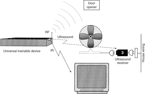
Dickey and Shealey (1987) also suggest that the specific tasks to be accomplished be identified both in an interview and by a home visit. Some tasks can be easily accomplished with an EADL, whereas others require different manipulation aids; a careful environmental survey can determine which tasks fall into each category. It is also important at this stage to understand the consumer’s expectations of an EADL and determine whether it is possible to meet these expectations. The consumer’s daily routine, the accessibility of her residence, the attendant care available, and the existence of other assistive technologies also affect the recommendation of an EADL. Finally, available funding to acquire the EADL plays a role in the selection of a system, and it may be necessary to set priorities among needs and tasks to allow for unknown funding amounts. Figure 14-14 illustrates an assessment form used in EADL evaluations (Barker, Gross, and Henderson, 1991). This form or an equivalent can be used to summarize the evaluation results, including the needs and EADL configuration, for an individual consumer.
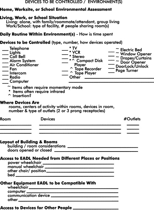
Figure 14-14 An evaluation form used for assessing environmental needs and goals. (From Barker P, Gross K, Henderson K: Control of the environment. In Proceedings of the ’91 RESNA Pacific Reg Conference, 1991, The Conference.)
The ConferenceThe outcomes of an EADL assessment include (1) identification of control sites and control interfaces, (2) determination of cognitive abilities related to understanding EADL operation, (3) listing of EADL functions desired (in priority order), (4) evaluation of the consumer’s motivation to use electronic environmental control, (5) a listing of other electronic devices that the consumer uses, and (6) identification of the environments in which the EADLs will be used. The listing of functions may include such things as lighting, TV, and drapery control. The listing of other electronic devices should include both consumer electronic devices, such as TV, CD/DVD player, computer, and speaker telephone (all with brand names and model numbers), and assistive technologies, such as communication devices and power wheelchairs. Armed with this information, it is then possible to work with the consumer to select an EADL that meets his or her needs.
Single-Device Binary Control Electronic Aids to Daily Living.
Electonic aids to daily living that control only one appliance can be useful in developing motor control and cognitive concepts such as cause and effect (for example, the Power Link, Ablenet, Minneapolis, Minn, www.ablenetinc.com). Chapter 7 describes a motor training program that uses these types of EADLs. Most of these have both momentary and latched modes, and they include a timer to activate the appliance for a preset number of seconds. These devices are useful when only a single device control can be understood by the user (e.g., in the case of developmental disability) or when only one device is required (e.g., a radio or light). The cost is low (less than $200), and there can be a significant increase in independence. The use of single-function EADLs often leads to the use of multiple-function EADLs or electronic communication devices (see Chapter 11). This progression is described in Chapter 7.
Matching the Characteristics of Multiple-Function Electronic Aids to Daily Living to the Needs of the User.
When an EADL is planned to meet specific needs, it is useful to group the tasks (determined during the assessment described earlier) into the five categories shown in Table 14-1. This grouping, based on the common ways of implementing specific functions, is the first step in specifying an EADL. After completing the assessment form, shown in Figure 14-14, the assistive technology practitioner (ATP) will know the type of appliances that need to be controlled. The EADL functions required can be identified in the left-hand column of Table 14-1. The corresponding information in the right-hand column identifies the methods available for EADL implementation. This allows options to be considered.
TABLE 14-1
Functions Performed by Electronic Aids to Daily Living
| Functions | Methods of Implementation |
| Binary latched control of AC appliances (e.g., lights, radio, on-off only) | House wiring transmission |
| Direct ultrasound control | |
| Discrete or continuous appliance (e.g., TV, VCR, CD, cassette tape control) | IR remote transmission |
| Momentary control of appliances (e.g., door opener, drapery control) | RF remote transmission |
| Telephone control | Hard-wired switch control |
| Switch control (any device requiring one or two switches) | Hard wiring IR link to switch box |
| Ultrasound link to switch box |
The first group in Table 14-1 is binary (on/off) latched (stays on or off until the next activation) control of appliances that operate from standard household wall current. As described previously, there are two basic ways that current EADLs control such appliances: (1) by plugging them into receivers that plug into the house wiring and transmitting control signals over the house wiring and (2) by direct ultrasonic transmission to a receiver into which the appliance is plugged. The most common commercially available components for use with house wiring transmission are the X-10 modules and controllers (X-10 Powerhouse, Inc., Northvale, N.J., www.X-10.com). These modules are incorporated into many EADLs. The major direct ultrasound receiver-based control device is the ElectraLink (TASH, Inc., Ajax, Ontario, Canada. www.tashinc.com). The second category in Table 14-1 is appliances that require discrete or continuous control, such as television channel selection or volume control. The most common EADL control method for discrete or continuous appliances is IR remote transmission, and several EADLs use integrated trainable or programmable IR controllers. This technology allows several devices (e.g., TV, CD/DVD) to be incorporated into one package controlled by the EADL. Each of these devices must have its own IR control to be incorporated into the trainable or programmable controller. The options available to the ATP depend on what appliances the consumer has and whether he or she has IR remote control. If IR remote devices are available, then the choice is to use an EADL with a trainable or programmable IR device. If the consumer needs continuous or discrete control but does not have IR-controlled appliances, then the ATP should consider EADLs with built-in discrete or continuous control, which may require modification of the appliance or purchase of a stand-alone IR controller.
If the consumer wants to control items such as draperies, then momentary control (i.e., the appliance is turned on for a variable period of time and then turned off) is required. For example, a drapery motor or bed elevation control may be turned on long enough to move the curtain or the bed to the proper position, and then the motor must be turned off. A latched control generally presents problems in this scenario. Very short activation times are not possible with latched control, especially if the user has delays in muscle motor response. In some cases the range of movement for the task is always the same (e.g., when opening a door), and a device that is started by the user and automatically stopped at the end of the task by the device (e.g., when the door is fully open or fully closed) can be used. This type of control is often implemented by using RF transmission. Hard-wired switch control can also be used for these functions. Common examples are the enlarged switches often placed near doors for persons with disabilities or the active floor mats or light sensors used to trigger the opening of these doors.
Telephone control is listed separately in Table 14-1 because the functions performed are different from other EADL tasks. Generally telephone controllers use switches connected directly to them (hard wired). Integrating all EADL functions is often desirable. If the consumer is also going to use IR continuous or discrete control, the ATP should consider the use of an IR-controlled telephone. This allows the consumer to control the telephone in the same way as the TV, CD/DVD, and so on.
The final category in Table 14-1 is for devices that require one- or two-switch control. Other examples of appliances requiring switch control are call signals and drapery and door controls. The simplest method to implement this type of control is hard wiring of the switch to the EADL component. However, this approach has two major disadvantages: (1) the user is forced to go to the device to be controlled and use the switch at that location, so flexibility in movement is limited and (2) it is difficult to integrate the switch control with other EADL functions into a total package controlled by only one control interface. If a consumer must use different switches for different devices, then independence can be reduced. If the individual does not have good motor control and requires careful positioning of the control interface for successful use, the problem is even more difficult.
One way to integrate switch control with other EADL functions is to use a component that can detect IR or ultrasound signals and generate a switch-type output. This type of output is sometimes referred to as relay output. For example, if the consumer is using a trainable or programmable IR EADL controller for TV, CD/DVD, and telephone use and needs to control a drapery motor as well, a two-output IR trainable switch box (as shown in Figure 14-15) can be used. The IR EADL can provide the equivalent of a switch output directly, and the consumer does not need to have two additional switches to control the drapes (e.g., one switch to open them and one switch to close them). Some EADLs have built-in switched or relay outputs.
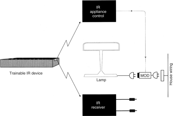
Figure 14-15 One approach to the integration of appliance control and single-switch or dual-switch control is to use an IR receiver that provides one- or two-switch closure outputs when activated. The two jacks shown in the lower right of the figure can be connected just as any switch would be.
Not all remote control uses IR transmission. Binary latched control of electrical appliances is often implemented by either ultrasound or RF transmission, and trainable or programmable IR controllers are not usable for these functions. Two basic approaches are used to integrate binary appliance control and remote IR controllers. The first of these, shown in Figure 14-15, has a control and distribution unit that uses IR transmission. The transmitted codes are used to select an appliance (the number of appliances can vary from 4 to 256) and the function to be accomplished (on/off or dim/brighten for lights only). The trainable or programmable IR device is programmed to recognize these codes, and the remote unit treats the appliance control and dual-switch receiver as IR-controlled devices.
The second approach to integration of discrete or continuous IR control with binary latched appliance control, shown in Figure 14-16, is to incorporate ultrasound and RF control into the trainable or programmable device together with IR transmission. In this case there is no need for a separate IR transmission distribution and control unit because the ultrasound and RF transmission is built into the trainable or programmable remote controller. This technology combines the trainability of the IR unit for TV, CD/DVD, and so on with the simplicity of direct ultrasound or RF transmission for binary control of appliances. This configuration allows more flexibility in the choice of individual environmental control components and allows us to focus on the needs of the EADL user rather than on the devices that may be available.
Hospital-Based Electronic Aids to Daily Living.
Individuals with a high-level spinal cord injury are hospitalized immediately after the injury and remain hospitalized for many months. During this time, they have needs for environmental control that are similar to those for home use, but their needs also differ in important ways. Jones et al (1980) list four advantages of using hospital-based EADLs: (1) increased independence, (2) increase in motivation for self-rehabilitation, (3) reduction in anxiety from helplessness, and (4) increased nursing time available for more essential services. As Efthimiou et al (1981) have found, an important factor in increased postdischarge use of EADLs is experience during the acute and subacute hospital-based rehabilitation phase. This is an additional advantage of hospital-based EADLs.
There is some controversy, however, as to when an EADL should actually be recommended and obtained (Ability Research Centre, 1999). Arguments for introduction of the EADL during the acute hospital phase of rehabilitation include developing a sense of control and possible independence in the patient and providing the system while there is significant support available for set-up and training. The arguments in favor of waiting until the patient returns home are that the person needs to learn to do as many things independently as possible with minimal assistance and the simplest level of technology possible should be used to accomplish this independence. A second reason for waiting is that the exact specifications and configuration of an EADL requires an assessment of the home environment and the recommendation should wait until the person has returned home.
To achieve these advantages, it is necessary to include features not commonly found in home-based EADLs. The first of these is inclusion of access to the nurse call system of the hospital. This requires that the EADL have an interface to standard hospital nurse call systems. A variety of control interfaces must be available for the patient to use in accessing this function. As Jones et al (1980) point out, it is often necessary to have one control interface usable during the initial, acute phase of injury (approximately 6 weeks after initial admission). Because of spinal shock, the patient often has greater paralysis during this phase than in later stages, and efforts to use residual limb movement will be compromised. They recommend using above-the-neck movements to activate the control interface during this phase. Respiration may also be more significantly compromised during the acute phase, which limits the use of puff-and-sip control interfaces. Finally, cervical traction may limit head movements during the acute phase. (Removal of the head traction apparatus often signals the transition from acute to subacute rehabilitation.) On the basis of these considerations, Jones et al (1980) have found that chin-controlled switches are the most generally useful during the acute phase of rehabilitation.
During the acute phase of rehabilitation, the patient is normally restricted to bed. EADL functions that are useful include television control (on/off, volume, and channel change), electric bed control, and appliance control (radio, lamp, fan). Although available on most hospital-based EADLs, telephone control is not frequently used during the acute phase of rehabilitation.
During the subacute phase of hospital-based rehabilitation, the patient generally has greater control because of the removal of the head traction apparatus, reduction of spinal cord swelling, and an increase in respiratory capability. These changes allow for more options in control interface selection. The patient also has greater interest in his surroundings, and telephone, television, and appliance control become more important to him. EADLs designed for hospital use generally do not have a wide range of options. For example, they may allow only one or two appliances to be controlled or they may have a small number of stored phone numbers (e.g., five). These design considerations reflect the unique requirements of the hospital situation. Other special features include very simple operation; large displays that are lighted for use in dim intensive care units; special electric bed and nurse control interfacing; and flexibility in the number of options and capabilities, depending on the needs of the user. Jones et al (1980) present design details for one computer-controlled hospital-based EADL.
Studies of Users of Electronic Aids to Daily Living
Several studies have been conducted to determine the preferred features and factors influencing successful application of EADLs. Most of the studies were conducted before some of the current features (e.g., trainable or programmable IR controllers) became available, but they still reflect basic preferences of users.
Symington et al (1986) studied the effect of EADL availability on attendant care in an institutional setting. Using a paired questionnaire for EADL users and nursing attendants in an institutional setting, they evaluated attitudes and perceptions of both users and staff regarding self-worth, independence, and usage of EADLs. The survey was administered before EADL system delivery and after EADL system use. For the users of devices, only one area (irritability) showed a statistically significant decline after EADL delivery. Perceptions of self-worth and independence increased, and users generally felt that they were less frustrated, had greater privacy, and needed to “bother” staff less frequently. The staff felt that the users had greater independence and that the staff was relieved of “extra duties” and saved time. An electromechanical counter recorded EADL usage, but no data were reported on frequency of use or usage patterns.
Woods and Jones (1990) reported on 10 years of experience with EADLs in institutional settings. They reported that EADL use can increase the independence of patients in such a setting. However, they also stressed the importance of training in proper use. Mann (1992) studied the use of EADLs by elderly nursing home residents. In this study, residents were divided into control and experimental groups. The experimental group received EADLs for use in their rooms to control lights and radios. They also received training in the use of these devices. Those in the control group did not have EADLs. Mann found that independent use of radios by the experimental group occurred at three times the rate of the control group at the end of the study. These results indicated that elderly nursing home residents will increase their environmental interaction if they have access to EADLs.
Studies have also been conducted on EADL use in community settings. Sell et al (1979) studied eight different EADLs over a 44-month period. Their subjects were persons with high-level (C4 or higher) spinal cord injuries who used the EADLs in their homes. Both groups were physically able to access the EADL functions. Features of EADLs that were judged valuable included visual and auditory selection displays, overall size and appearance (fitting into a home), ability to make confidential telephone calls with an automatic telephone dialer, direct access to telephone dialing (rather than using the operator), and reliability. Reliability was judged by the absence of failures of the device or of operational errors by the user.
Efthimiou et al (1981) studied the impact of EADLs on the postdischarge lives of persons with spinal cord injuries. Identified factors related to EADL use included gender (74% of men chose to use EADLs, whereas only 14% of the women did), exposure to an EADL during the in-hospital rehabilitation process, and availability of EADL systems (including funding) after discharge. They also looked at scales of activity and correlated these with EADL use. One substudy included 13 EADL users and 7 nonusers, all men. All the users were employed compared with only 54% of the nonusers. Another difference between the user and nonuser groups was that users more frequently participated in educational activities, phone calls, and travel, whereas nonusers spent more time in passive recreational activities. Users more frequently used assistive devices in general, and they performed more tasks independently than did the nonusers. In this study, use or nonuse was unrelated to adjustment to the disability and personality type. The major reasons given for not using an EADL were lack of space and an inaccessible home.
McDonald, Boyle, and Schumann (1989) studied EADL use by persons who had incurred high-level spinal cord injuries. In contrast to earlier studies that had used very small samples, these authors had 29 subjects accessed through the manufacturers who had provided their EADLs. More than 90% of their sample of EADL users found them to be helpful and more than 70% felt that EADLs increased their independence. The group of users also indicated that the EADL positively affected their disposition (67%) or was neutral in this regard (33%). The needs for EADL use were ranked in order of importance: communication, security/health, recreation, household tasks, employment, and education. EADL functions judged important (in rank order) were telephone, television, room lights, emergency signal, door, and computer. The 29 respondents also indicated that they were comfortable and felt secure for longer periods alone when an EADL was available.
Rigby et al (2005) investigated the psychosocial impact and functional performance of EADL use in the home by comparing a group of users (n = 16) and a group of nonusers (n = 16), all of whom had sustained cervical spinal cord injuries. They found that functional abilities were greater (as measured by standardized functional task instruments) and the psychosocial impact was positive for competence, adaptability, and self-esteem (as measured by the Psychosocial Impact of Assistive Devices Scale [PIADS]). In contrast to these studies of EADLs that reported only general opinion and did not objectively measure actual usage, Von Maltzahn, Daphtary, and Roa (1995) monitored usage of EADLs in home settings. They used a data logger that kept track of time and type of activation over a 16-week period and found that the greatest usage was in the evening and the largest activity was in television control. The small sample of subjects (five) showed great variability as well, with a factor of almost 30 times between the greatest and least number of uses of the EADL per week. Von Maltzahn, Daphtary, and Roa (1995) also used an end-of-study questionnaire to determine perceptions and attitudes of the users and their care providers. Once again the importance of training was cited, and both users and caregivers indicated that there was greater user independence and fewer demands made on the caregivers.
Jutai et al (2000) used the PIADS (see Chapter 4) to evaluate the psychosocial impact of EADLs. The goal of this study was to determine the perceived benefit of EADLs to the consumer’s quality of life. Two groups were included: users of EADLs and those for whom EADLs were appropriate but who had not yet received them. Users’ perceptions were measured at two points 6 to 9 months apart to determine the stability of the perception of psychosocial impact. Jutai et al found that EADLs produced similar degrees of positive impact on users and positive perceptions of anticipated impact on those without EADLs. The two measures of those using EADLs indicated that the psychosocial impact was stable over the time frame used. This study demonstrated the utility of the PIADS as an instrument for quantifying the psychosocial impact of assistive technologies.
In a similar study, user’s perceptions of the benefits of EADLs were evaluated throughout the assessment and acquisition process using the PIADS (Ripat and Strock, 2004). In the preacquisition phase, potential EADL users predicted that there would be positive impact on feelings of competence and confidence and that an EADL would enable them in a positive way. One month after obtaining an EADL, the perceptions were still positive but less so than in the preacquisition phase. After 3 to 6 months the level of positive perception had returned to the preacquisition level, indicating that the original predictions were actually met. The most likely reason for the reduced positive impact perception in the middle phase is that the users were learning the new device and were adjusting to carrying out activities of daily living in a new way with the EADL.
Ripat (2006) reported results of a follow-up study. This study found that the positive benefits were sustained over time, as measured by the Canadian Occupational Performance Measure (COPM) and PIADS. (See Chapter 4 for a description of both measures.) Both new and more experienced users perceived an overall positive impact of EADLs (Ripat, 2006). Both the COPM, which measures an individual’s perception of performance and satisfaction with performance in activities of daily living, and the PIADS, which measures the impact of assistive technology on an individual, yielded positive results that were highly correlated with each other. The use of EADLs for a short trial period of 2 weeks also decreased frustration, increased independence, and decreased the time to complete tasks (Croser et al, 2001).
Examples of Electronic Aid to Daily Living Application
To illustrate the process of configuring EADLs for specific needs, several case examples are described. Each of these cases is based on an actual situation faced by a person with a disability (Cook and Hussey, 1992). Gross (1992) presents a detailed case study of EADL use by a person with a high-level spinal cord injury. She also describes a process for analyzing needs and converting them into EADL specifications.
ROBOTIC AIDS TO MANIPULATION
Because robots or robotic systems are intended to assist with manipulation, they are a natural alternative manipulation device for persons who have disabilities. There are, however, some significant differences between the use of robots by persons with disabilities and their use industrially. Industrial robots often have the role of replacing the human operator for reasons of strength, safety, or precision. In production line environments (e.g., automobile manufacturing), it is often necessary to lift large or heavy objects and position them for attachment to other parts. Robots are stronger than humans and are not subject to fatigue after hours of service. Many work environments are hazardous (e.g., those involving radiation or very high or low temperatures). To ensure safety of the operator, handling of objects in these environments is done by a robotic manipulator controlled by the human operator. At the opposite extreme from heavy object positioning is the repeated assembly of small parts (e.g., electronics assembly). Robots can be programmed to carry out the exact same task over and over without fatigue or loss of accuracy. In each of these cases the human is an ancillary part of the total system.
In contrast, in assistive robotics the human operator is at the center of the process. Instead of replacing the human operator, the goal is to enhance his or her ability to manipulate objects and to function independently. This makes issues of safety more important for assistive robots. To ensure safety, forces are kept within 1 or 2 pounds (2 to 5 kg) and velocities are less than 10 cm/sec (Seamone and Schmeisser, 1985). Assistive robots perform many functions, in contrast to the relatively limited repertoire of an industrial robot. Although some tasks (e.g., feeding) are repeated, the assistive robot must be able to carry out totally unplanned movements spontaneously. This section discusses the development and application of assistive robots. In contrast to technologies discussed in other sections of this chapter, assistive robots are still largely in the research and development stage, and application of these systems is not yet widespread.
Stanger and Cawley (1996) evaluated the incidence of 12 disabling conditions associated with reduction of upper limb function. These were cerebral palsy, arthrogryposis, spinal muscular atrophy, muscular dystrophies, rheumatoid arthritis, juvenile rheumatoid arthritis, multiple sclerosis, amyotrophic lateral sclerosis, poliomyelitis, spinal cord injury, head injury, and locked-in syndrome. On the basis of the incidence of these conditions, the authors estimated that approximately 150,000 persons in the United States have limitations of upper extremity function and could benefit from a robotic aid.
History of Powered Manipulators
Early rehabilitative manipulators were powered orthoses. An orthosis is an external brace that supports a body part. By adding motors to the joints (i.e., wrist, elbow, and shoulder) of an upper extremity orthosis, Corell and Wijnschenk (1964) developed one of the first rehabilitative manipulators. This system had four degrees of freedom (independent movements) and was controlled by a minicomputer. Another orthotic approach was the Rancho Arm (Corker, Lyman, and Sheredos, 1979). This system also used an external upper extremity splint, but it had seven degrees of freedom. This allowed control of the shoulder (abduction-adduction and flexion-extension), elbow (flexion-extension), wrist (pronation-supination, radial and ulnar deviation, flexion-extension), and fingers (grasp-release). Each degree of freedom was controlled by a bidirectional tongue-activated switch. This single-joint control made it difficult to carry out complex movements. To understand this, place a pencil or pen on the table. Now reach for it and pick it up, but only move in one of the degrees of freedom (i.e., one joint) listed above at a time. This type of movement takes great concentration. Now, reach for the pen or pencil as you normally would. This is called end-point positioning, and it is much easier to accomplish, but it makes the control system and robot much more complicated. The difficulties associated with controlling individual joints were a major downfall of early rehabilitation manipulators, and most current assistive robots use end-point positioning.
In the late 1970s and early 1980s, stand-alone assistive robots began to be developed. These devices were generally table mounted, but some were mounted to wheelchair frames or lap trays. These robots were more versatile because they did not have to support and move the user’s limb, but they created new challenges because they were not attached to the body. The user had to develop a new coordinate system for controlling the robot, one related to the workspace of the robot rather than to his own body. The rapid development of microcomputers allowed miniaturization of the controllers while adding more sophistication. These systems also were capable of being “trained” to carry out repeated tasks. These advances made everyday use of assistive robots more feasible.
The remainder of this section discusses currently available assistive robots and their application. Three types of applications are discussed: (1) fixed workstations, which are built around assistive robots; (2) mobile robots for use in work, home, and school settings; and (3) robots developed and used to meet the educational goals of children. Each of these systems is a general-purpose manipulation device, as opposed to special-purpose manipulation devices such as the feeders and page turners described earlier. In some cases there is a blurring between these two categories. For example, we describe the Handy 1 (Topping, 1996) under electrically powered feeders, but it is actually a special-purpose robotic arm.
Robotic Workstations
A workstation can be defined as an area dedicated to the performance of a specific job or activity. Examples of activities are design (e.g., a computer workstation for engineering students), reading (e.g., a library-based workstation), and clerical tasks (e.g., a workstation for word processing, telephone answering, and manipulation of files). These workstations involve manipulation of papers, books, and other devices. When the user of the workstation has difficulty with upper extremity function and manipulation, desktop robots can play a major role in creating full access to the workstation. Because the workstation is fixed in one location, the design of the robotic system can focus on manipulation of objects only, rather than movement to the object and then manipulation of it. Two robotic workstations that have been evaluated in the workplace are described. Both these systems were developed by the Veterans Administration.
Applied Physics Laboratory Robot Arm Worktable System.
The Applied Physics Laboratory Robot Arm Worktable (APL RAWT) system is built around a powered upper extremity prosthesis that has four degrees of freedom: (1) shoulder flexion-extension, (2) elbow flexion-extension, (3) wrist pronation-supination, and (4) hand grasping (Seamone and Schmeisser, 1985). In the workstation the prosthetic arm is mounted on a turntable, which allows a fifth degree of freedom comparable to internal-external shoulder rotation. Finally, the entire arm and turntable assembly is mounted in a track that allows it to be moved from front to back of the work surface. This results in a total of six degrees of freedom for the arm. The movements of this arm are shown in Figure 14-17, together with the total size of the reachable workspace. There are three motors for the six degrees of freedom. One DC motor controls elbow flexion-extension, wrist pronation-supination, or shoulder flexion-extension, depending on the commands sent. The second motor controls turntable rotation or hand grasping. Any joint not being activated is kept in place with a solenoid lock. This allows one motor to serve several functions at different times, but it prevents multiple joint movements simultaneously. The third motor is a geared servomotor used for positioning the arm in the front-to-back track.
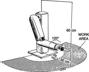
Figure 14-17 The coordinate system and working envelope of the APL RAWT system. (From Seamone W, Schmeisser G: Early clinical evaluation of a robot arm/worktable system for spinal-cord-injured persons, J Rehabil Res Dev 22:38-57, 1985.)
The APL RAWT was designed for use by persons with high-level spinal cord injuries (SCI). This limited the choice of control sites to the head, neck, and voice. Chin control was chosen over other control modes (e.g., speech recognition or sip-and-puff) because of its compatibility with power wheelchair control. Because many persons with SCI have experience using chin control for wheelchairs, training in the use of the RAWT would be decreased. Lateral movement of the modified chin control allows wheelchair steering. Reverse is activated by a microswitch located on the chin control lever. When the user approaches the RAWT in the wheelchair, contact is made between the RAWT and the wheelchair by an optical (IR) link. The user lifts the chin control briefly and control is transferred from the wheelchair to the RAWT. The user controls the RAWT with the chin joystick (left/right, in/out) and two additional switches (up/down).
Two basic modes of control are provided. First, the user may activate any one degree of freedom and control the arm in that axis. As discussed, this can be tedious and difficult, but it is sometimes necessary for precise movements. The second and most common method of control is to select one of the prestored specific tasks. Examples of some of these tasks are given in Box 14-1. As is shown in the box, the APL RAWT combines the high technology of the robot with the low technology of a mouthstick for some tasks. For example, the robot can bring the mouthstick holder into position for the user and then bring the telephone into position. The user can dial the telephone using the mouthstick. Likewise, a book or magazine can be positioned in a reading stand by the robotic arm, and the mouthstick can be used to turn pages. To select a prestored task, the user activates a menu of choices using the chin joystick and then searches through a list of tasks on the display screen to select the one wanted. Once the task is chosen, the arm automatically executes it. For some tasks such as feeding, there are intermediate points at which the user must reactivate the control. For example, a spoon of food is brought to mouth level and the arm is stopped. The user takes the food off of the spoon and then initiates a new cycle. Tasks such as self-feeding require the use of additional components, such as adapted bowls and utensils.
A block diagram of the total APL RAWT system is shown in Figure 14-18. The entire system is controlled by a special-purpose computer microprocessor. A keyboard is provided for programming new movements and general interaction with the system. It can be used by either the consumer or an attendant or therapist. Function keys on the keyboard specify robot motions. Prestored movements can be edited by use of the keyboard. This increases the flexibility because a new movement task can be created by editing an existing task that is similar.
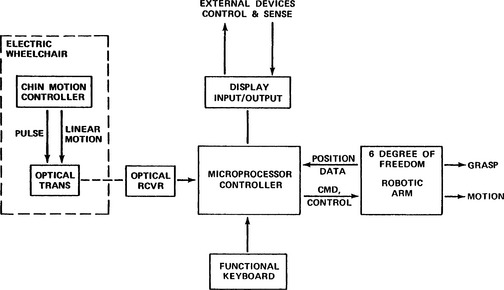
Figure 14-18 Block diagram showing the component parts of the APL RAWT system. (From Seamone W, Schmeisser G: Early clinical evaluation of a robot arm/worktable system for spinal-cord-injured persons, J Rehabil Res Dev 22:38-57, 1985.)
The APL RAWT was clinically evaluated at three Veterans Administration centers. A total of 20 evaluators with high-level SCIs participated in clinical trials. The RAWT was typically set up in the evaluator’s residence. Often this was the evaluator’s home, but for some evaluators the residence was a Veterans Administration medical center, nursing home, or state institution. The most popular features were self-feeding and computer and telephone use. Inadequacies of the chin controller were the most frequently cited negative feature. Seamone and Schmeisser (1985) discuss the evaluation of the APL RWAT in detail. The overall impression of the system was that it had the potential to be very effective for individuals with SCIs, but it needed further development and refinement.
Desktop Vocational Assistant Robot.
The Desktop Vocational Assistant Robot (DeVAR-IV) system is built around an industrial-grade, low-payload robotic arm (PUMA-260) mounted on an overhead track (Figure 14-19) (Hammel, Van der Loos, and Perkash, 1992). This system has a primary goal of vocational assistance. DeVAR-III used a table-mounted PUMA arm, and the emphasis was on completion of tasks of daily living (Hammel et al, 1989). The DeVAR human/technology interface includes speech recognition (Votan VPC-2100) and multiaxis joystick control, coupled with a color monitor and voice synthesis. The voice synthesis is for user feedback (e.g., to confirm a task selection) and for warning messages. The monitor displays command prompts and robot status during task completion. The processor is a dedicated computer with appropriate software. A task-oriented programming language (VAL-II) is used. Using this language, routines can be developed for specific tasks. Example tasks for self-feeding are listed in Table 14-2 (Hammel et al, 1989). Once a task is initiated, commands are issued by the user for specific functions within the task. Examples of these are shown in Table 14-3 for the task of eating soup listed in Table 14-2. Note that some commands (e.g., SOUP) have different meanings at different times during the task. Other commands (e.g., USE) are repeated many times to recycle through a subtask under the user’s control. The user can also pilot the arm by using basic commands such as RIGHT, LEFT, BACKWARD, FORWARD, UP, DOWN, STOP, GO, OPEN, and CLOSE (gripper). As shown in Table 14-3, these direction commands can also be used within a prestored task. All the commands are spoken by the user and entered by the voice recognition system. The user must train the speech recognizer (see Chapter 7) to recognize her speech. For a typical vocabulary of about 60 commands, this takes approximately 10 minutes (Hammel et al, 1989). Similar tasks and command sequences can be developed for other applications (e.g., vocational work site tasks).
TABLE 14-2
Desktop Vocational Assistant Robot Tasks and Their Commands
| Task | Command |
| Prepare a bowl of soup | SOUP |
| Eat the soup with standard spoon | SPOON |
| Brush teeth with electric toothbrush | TOOTHBRUSH |
| Wash and dry face with adapted washcloth | WASH |
| Shave face with electric shaver | SHAVE |
Modified from Hammel J et al: Clinical evaluation of a desktop robotic assistant, J Rehabil Res Dev 26:1-16, 1989.
TABLE 14-3
Desktop Vocational Assistant Robot Commands Used to Prepare and Eat Soup
| Command | Action |
| SOUP | Robot takes soup out of refrigerator, puts in microwave, closes door, sets time, heats soup. |
| SOUP | Robot brings soup from microwave to table. |
| SPOON | Robot gets spoon from tool holder and brings to neutral point in front of user. User says direction commands to bring spoon near mouth (UP, DOWN, LEFT, RIGHT, BACKWARD, FORWARD). Robot remembers this point and returns to it each time. |
| USE | Robot scoops a spoonful of soup and brings to user’s mouth. User says USE for each mouthful until finished eating. |
| BACK | Robot returns soup to refrigerator to finish later |
| CLEAN | Robot puts bowl in dirty dish container to be cleaned |
Modified from Hammel J et al: Clinical evaluation of a desktop robotic assistant, J Rehabil Res Dev 26:1-16, 1989.
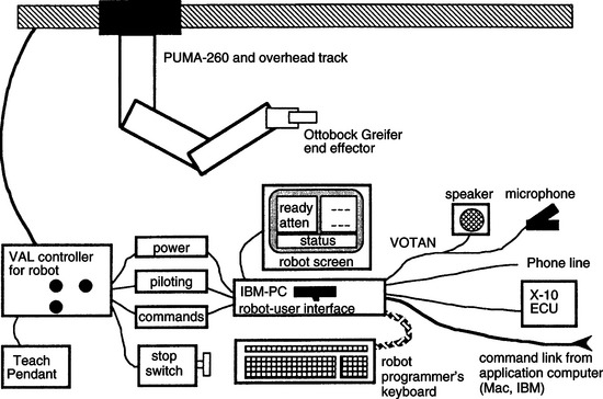
Figure 14-19 Basic components of the Desktop Vocational Assistant Robot (DeVAR). (From Hammel JM et al: Clinical evaluation of a desktop robotic assistant, J Rehabil Res Dev 26:1-16, 1989.)
Outputs include environmental control (by an X-10 system) and the robotic arm. Examples of tasks that various versions of DeVAR have performed are listed in Box 14-2 (Hammel et al, 1989). The use of an industrial-grade robotic arm has the benefit of providing more precise control, proven safety features and reliability, and greater payloads, but the cost is significantly higher than robotic manipulators designed for educational or assistive uses. The gripper is a modified Otto Bock prosthetic hand (Otto Bock, Minneapolis, Minn., www.ottobock.com).
Two versions of the DeVAR have been field tested. DeVAR-III was evaluated by Hammel et al (1989). Twenty-four male evaluators were either inpatients or outpatients of the Palo Alto Veterans Administration SCI Center. Twenty-one of the evaluators had SCIs at the C4 or higher level, and all had little or no functional upper extremity movement. Each subject was given training by both an OT and an engineer. The speech recognition system was trained to recognize 60 command words. Both preprogrammed movements (e.g., those in Table 14-3) and directional movements were used by the participants. Pretests and posttests were administered using voice commands on the computer to evaluate the user’s perception of the usefulness of the robotic system. Participants indicated a high degree of satisfaction with the performance of the robot in the tasks shown in Table 14-3. They also expressed a preference for the robot over attendant care for these tasks. The major concerns expressed were about reliability, the amount of space the robot occupied, and safety with children. Overall pretest ratings were lower than posttest ratings, reflecting a lack of knowledge of how well the robot would perform and a degree of skepticism in the pretest. Hammel et al (1989) discuss the evaluation results in more detail.
DeVAR-IV, the version developed for a work environment, has also been evaluated (Hammel, Van der Loos, and Perkash, 1992). A single-subject research design was used with two components (R = robot assistance; A = attendant assistance). The workstation used by the evaluator also included a speech recognition keyboard and mouse-emulating device for access to his computer workstation (see Chapter 7). The evaluator was a 50-year-old man with a C4-C5 SCI. He was employed full time as a database programmer for a utility company. He used the DeVAR-IV system for his normal office activities and for some daily living tasks (e.g., serving lunch, emptying his leg bag, dispensing medications). The DeVAR-IV system was installed in his office for 6 months before data collection. This ensured that the evaluator was fully trained in and comfortable with the use of DeVAR-IV. During the first phase of data collection, the robot was used for six 10-hour days (corresponding to his normal workday of 10 hours). During the second phase (A) the robot was turned off and the attendant performed its tasks. All sessions were videotaped and observed by two project staff members. The evaluator expressed a preference for the robot over attendant assistance for all activities except feeding. When the robot was used, attendant assistance could be replaced for two 5-hour periods during the workday. Complete replacement was not possible because of required setup tasks (e.g., meal preparation for feeding by the robot). The replacement of personal assistant care is a major factor in determining the economic feasibility of the robot system. Hammel, Van der Loos, and Perkash (1992) show a projection (based on $7 per hour attendant care and a $50,000 robot) that makes the robot less expensive after a period of 5.5 years. Installation, training, and continuing maintenance costs for the robot are included in their analysis.
Birch et al (1996) carried out a study to determine actual costs of using a robotic assistant compared with using a personal assistant for office-related tasks. They used a simulated office environment and standardized tasks. They found that, although the robotic assistant did reduce assistant time and therefore cost, it also resulted in decreased productivity by the user. They attributed this reduction in productivity to waiting times necessitated by robotic movements, which were slower than the corresponding human attendant actions.
Mobile Assistive Robots
Because we rarely do all our manipulation from a fixed location, mobile assistive robots have been developed. These fall into one of two general classes: (1) wheelchair mounted and (2) mounted on a mobile base that is controllable by the user. The major limitation of the first approach is that the most functional robot arms are relatively large. This large size, coupled with the other apparatus that must be attached to the wheelchair, makes attachment of the arm to the wheelchair impractical in many cases. Recent miniaturization of these arms has solved this problem. The separate mobile base approach solves these problems, and it is practical in the home or at the work site. However, this approach also has disadvantages. The mobile robot requires that the user add “steering” to the required control commands. Because the user of a robot most likely has a restricted set of control signals available, the addition of these steering commands may be impossible. It is also difficult to transport the mobile base from one location to another. It is like having two powered wheelchairs to transport. Thus the most practical application of mobile robots is within one location. This location can, of course, include all rooms in a house or any location within a school, factory, or office.
Wheelchair-Mounted Robotic Arms.
The Manus manipulator, pictured in Figure 14-20, is a robotic arm mounted to a wheelchair (Verburg et al, 1996). It was designed to serve as a general-purpose manipulative aid for people who have severe upper extremity limitations. The robotic arm has eight degrees of freedom, can lift a 1.5-kg (3.3-pound) weight when the arm is fully extended, and can exert a gripping force of 20 N. The arm weighs 20 kg (9.09 pounds). Verburg et al (1996) describe the development of the Manus system, including several clinical and community-based trials that were used to gain user feedback. Clinical trials of early versions of the Manus arm identified two major problems: (1) the limited interface options and (2) the fact that when the Manus arm was mounted to the wheelchair, the weight and width of it were increased too much.
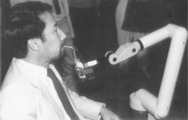
Figure 14-20 The Manus wheelchair-mounted robotic arm. (Courtesy C.W. Heckathorne, Northwestern University Rehabilitation Engineering Research Center, Chicago, Ill.)
Since these trials, several generations of this arm have been developed and multiple user interfaces have been tried. These include a multidimensional joystick, head control using either a joystick or the frontalis muscle electromyograph, enlarged keyboard, and foot control. There has also been work to integrate the Manus control into the wheelchair control system. The latter was strongly recommended by user trials and provides a major improvement in integration of functions for the user. These changes have addressed the first of the early clinical trial concerns. A new mounting system, which includes moving the Manus out of the way when other activities are to be carried out, has addressed the second concern.
A technology assessment to determine the requirements for prescription and funding of the Manus system was carried out in the Netherlands from 1992 to 1993. This review included criteria for both the user skills required and the development of a set of prescription indicators. The report recommended that potential users should have minimal or no hand function or limited coordination of the upper extremities, inability to lift their arms against gravity, limited reach, use of an electric wheelchair, inability to feed or drink independently, and inability to manipulate objects. Indicator diagnoses included spinal cord injury, multiple sclerosis, rheumatoid arthritis, progressive dystrophies, and severe spasticity (e.g., cerebral palsy). User activities that were determined to be important for use of a Manus system included the need to engage in activities at different locations, an inability to function without assistance for large parts of the day, a living setting in which absence of a system like Manus would constitute an unacceptable load for family, and the ability to begin or resume work or school if a Manus were available. Motivational and cognitive criteria included general motivation to use Manus, ability to understand and remember the technical commands, and general familiarity with computers. The technology assessment also recommended that a 3-month trial period in the community occur before final prescription approval. Criteria for evaluating the outcomes of the trial to determine whether final funding would be approved included whether the Manus was being used in the locations and for the purposes specified in the evaluation, whether the Manus had increased the user’s independence, and how the Manus had affected the roles of aides and family members (e.g., increased or decreased time required for assistance and by how much). On the basis of this technological assessment, the Manus was approved for funding in several European countries.
Use of the Manus system was also evaluated by 14 individuals in six European countries (the Netherlands, Germany, Norway, France, Italy, and Switzerland) (Oderud, 1997). These community-based evaluations demonstrated that the Manus manipulator was frequently used at home for activities of daily living (e.g., fetching objects, eating and drinking, preparing food in a microwave oven). Limitations in this home environment included the added size and weight of the wheelchair when the Manus was mounted to it (despite its redesign) and the need for training of the user and significant others. In these studies the Manus was not frequently used for vocational tasks. The major limitation in this context was that the Manus could not be preprogrammed for repetitive tasks, which added to the cognitive load of the user in the work environment, where speed of task performance was more critical.
There are still relatively few (less than 100) Manus systems in daily use by persons with disabilities. Cost, lack of understanding of the potential value of robotics, minimal infrastructure for marketing and support, and the need for training of users and professionals are the most often cited reasons for this slow growth in consumer base for this technology (Oderud, 1997; Verburg et al, 1996).
Ivlev et al (2005) added sensors to the Manus arm to attempt to overcome its relative inaccuracy and to make it more autonomous. The basic approach was to detect the location of objects to be manipulated and to automate the manipulation process, relieving the person from complex instructions. They called their robots FRIEND I and FRIEND II. Cameras were mounted to the back of the wheelchair above the person’s head to visualize the work envelope and in the gripper to detect that the object to be manipulated was in range. A scale and touch pad were mounted in a lap tray to give additional information about object location and weight. The FRIEND robot is shown in Figure 14-21. By providing information about location and weight of objects, it was possible to program the system to identify specific objects (e.g. a bottle and glass) and to execute a task with those objects (e.g., pour from the bottle into the glass). This allowed the user to issue commands like “find glass” rather that having to manipulate the arm through more primitive commands of moving up/down/left/right to reach the glass. Thus, with the automated system a task that required 20 instructions without automation was reduced to 5 instructions with the FRIEND robot. Friend II differed form FRIEND I in hardware (a pneumatically control gripper with individual fingers was added) and more sophisticated positioning software.
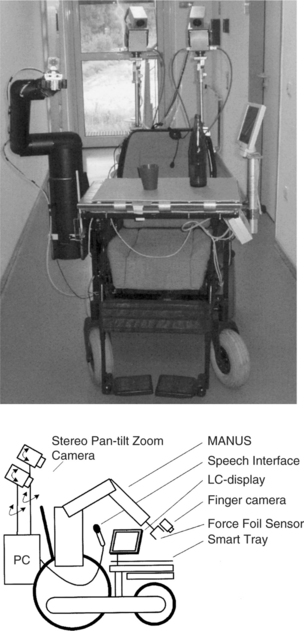
Figure 14-21 The FRIEND robotic arm system. (From Ivlev O, Marterns C, Graeser A: Rehabilitation robots FRIEND I and FRIEND II with the dexterous and lightweight manipulator, Technol Disabil 17:111-123, 2005.)
The Raptor robotic arm is the first such assistive technology device to be approved by the U.S. Food and Drug Administration (Mahoney, 2001). The Raptor is similar to the Manus in function with four degrees of freedom and attachment to the wheelchair frame (giving two additional degrees of freedom). A joystick, keypad, or sip-and-puff switch can control it. The Raptor emphasizes mobility, payload, and reduced precision with a 48-inch extension and it can lift up to 4 pounds. The Raptor requires cognitive skill to position the gripper because some positions and orientations can only be achieved by moving the wheelchair (and the user). The intended user population is the same as for the Manus.
Another wheelchair mounted arm that is under development is the Middlesex University rehabilitation robot (Parsons et al, 2005). The design goals for this prototype focused on low cost, general-purpose applicability, function driven by user prioritization of tasks to be completed, wide range of input options, and a variety of control modes and safety. The resulting prototype used a design that reduced the number of joints that oppose gravity, reduced the weight of the arm (by holes drilled in the material that were not weight bearing), and used telescoping components to reduce overall size while increasing rang of operation. The engineering drawing for the Middlesex arm is shown in Figure 14-22. The control software provides for cartesian coordinate positioning in space (as opposed to requiring that each joint be controlled separately) and a “teaching” function that records a trajectory or routine for later replay.
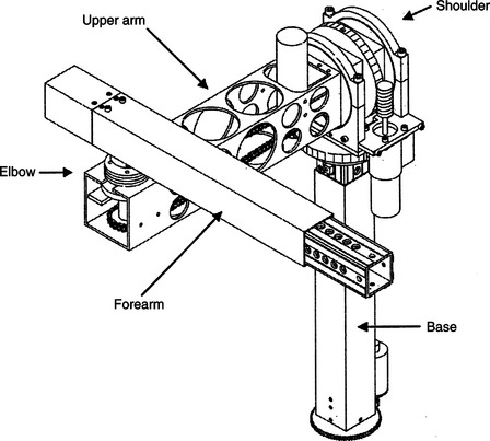
Figure 14-22 Engineering drawing of the Middlesex rehabilitation robot. (From Parsons B et al: The Middlesex University rehabilitation robot, J Med Eng Technol 29:151-162, 2005.)
The FRIEND and Middlesex robots offer improvements on earlier robots, but they have yet to be thoroughly evaluated in a daily living setting. Their development does help identify the major limitations that users and engineers have addressed on the basis of evaluation of earlier commercial robots such as the Manus and the Raptor.
Mobile Vocational Assistant Robot.
The Mobile Vocational Assistant Robot (MoVAR) represents a specially configured robotic system developed for assistive applications. Many of the components of DeVAR are included in MoVAR (Van der Loos, Michalowski, and Leifer, 1988). These include the PUMA-260 robotic arm, a speech recognition control interface (Votan), a multiaxis joystick control, a task-oriented programming language (VAL-II), and a host-computer menu command interface. To meet the goals of mobility, two major additional components are added to the system. The first of these is a mobile base that is specially designed to allow easy movement in any direction in a small space. Specially designed and built wheels allow this flexibility in movement. Second, an expanded sensing system is added. A small camera is mounted on the robotic arm. This camera image is displayed directly to the user, and its image is used in modeling the environment for task-level programming. Touch-sensitive bumpers that can determine whether to stop (e.g., at a wall) or to push harder (e.g., to open a door) are also included in the MoVAR. The MoVAR is about the same size as a powered wheelchair. The systems described in this section are examples chosen because of their design goals and their clinical evaluations. Several other robot systems are under development.
Use of Robotics in Education
Most rehabilitative robotic systems have been designed for adults (e.g., those with high-level spinal cord injuries), and their control requires relatively high-level cognitive skills that exceed the developmental level of younger children (Van Vliet and Wing, 1991). Severe physical disabilities may also limit the access to standard rehabilitation robots (Eberhardt, Osborne, and Rahman, 2000). The educational setting places additional constraints on the robot system. First, the user may be very young, which necessitates simplified, age-appropriate control schemes and user interfaces. Second, a robot that is intended for use by young children has added safety demands because school children cannot be expected to exercise the same caution as adults.
For young children, manipulative tasks contribute to the development of cognitive and language skills (see Chapter 3). Robotic devices that aid manipulation can help young children with limited physical capabilities to develop these cognitive and language skills as well as directly aid manipulation. Cook, Liu, and Hoseit (1990) carried out a study to determine whether very young children would interact with a small computer-controlled robotic arm. Six disabled and three healthy children, all less than 38 months old, were used in the study.
The system consisted of a microcomputer for control and data collection, a small robotic arm (about half the adult human scale), and a guidance unit used to train the arm to make specific movements (Cook et al, 1988). The arm can rotate around its base; flex and extend at the elbow and shoulder; extend, flex, supinate, and pronate the wrist; and open and close the gripper. The guidance unit used a joystick to train the arm by moving the joystick in the desired direction of arm movement. This made it intuitively simple for a teacher, therapist, or parent to train a specific movement that was of interest to the child. Three phases were used: (1) training the arm for a specific movement, (2) playback of the movement by the child using a single switch, and (3) monitoring the child’s behavior during arm movement. Training of the arm was done by either using the guidance unit or by entering a series of text commands to train the arm. Using the guidance unit, the teacher, therapist, or parent moves the arm through the desired movement with the joystick, and the movement is stored for later playback. In the text training mode, commands such as 100 FORWARD (move the arm forward 1 inch) were typed and combined to form a complete task (e.g., bringing a cracker within reach of the child or dumping the contents of a cup).
In a typical task a child used the robot arm as a tool by pressing the switch only when it was necessary to bring an object closer to him or to uncover a hidden object (e.g., by tipping a cup containing an unknown object), and the child did not press the switch when he or she could reach the object. This tool use is unique to a robotic arm compared with toys or computer graphics used as contingent results, and it provides additional information over these simpler modes of interaction regarding the child’s skills. Fifty percent of the disabled children and 100% of the healthy children interacted with the arm and used it as a tool to obtain objects out of reach. All the disabled children with a cognitive developmental age of 7 to 9 months and older did interact with the arm, whereas those below this developmental level did not. Gross and fine motor skill levels were less related to success in using the robotic arm than were the levels in cognitive and language areas. This study showed that very young children will use a robotic arm to accomplish tasks that are of interest to them.
Open-ended tasks such as drawing have also been carried out using single-switch scanning with the Handy 1 Robot (Smith and Topping, 1996). In this case, selection of the color of a pen, the position of the pen, up (move) or down (draw), and the pen’s movement are accomplished with single-switch scanning. Tasks such as these are cognitively demanding, and widely varying levels of success were reported for the three subjects included in the study.
To facilitate the development of more complex tasks, it is necessary to move beyond single-switch playback for a movement. Cook et al (1988) developed a hierarchy of robotic movements that sequentially increased the complexity of the tasks the child needs to accomplish. These are related to the cognitive developmental levels described in Chapter 3. The child progresses from understanding simple playback of complete movements, to segments of movements, to complete control of the end point. Nof, Karlan, and Widmer (1988) used a two-level system for developing a child’s interaction with a robotic arm. At the first level, the arm functions to carry out complete tasks. Sublevels included by Nof, Karlan, and Widmer were one- and two-step sequences, each used to carry out the same task. At the second level, the robotic arm allows the child to control component actions and incorporate these into more complex sequences.
Cook et al (2000) used a robotic arm to determine whether children (aged 4 to 7 years) who have severe physical disabilities would be able to understand a sequence of motor actions and to use them to find buried objects of interest. The robot was adapted to allow control by children with severe disabilities (Cook et al, 2000). The system was programmed to (1) carry out preprogrammed movements when the child hit a switch, (2) execute three-dimensional cartesian coordinate movements when activated by one of six switches or keyboard keys, and (3) move any of the six degrees of freedom and open or close the gripper when one of 14 switches or keyboard keys was pressed. Enlarged keyboards that reduced the physical demands for high-resolution movements by the child could be used instead of single switches. Three specific robotic arm movements, each executed by a single switch press, were programmed. Dry macaroni in a tub was used to provide both sensory and motor interactions for the child. The tasks used included the following: (1) macaroni was dumped from a glass held by the robotic arm (one switch); (2) the child controlled the arm to dig an object out of the macaroni and then dump the macaroni and the object (two switches); and (3) the child caused the arm to move laterally to a location where an object had been buried, dig the object out of the macaroni, and dump the macaroni into the tub (three switches). The buried object was a plastic egg containing another object of interest to the child (e.g., finger puppet, small rubber stamp). Cook et al (2000) reported that children generally attended to tasks for significantly longer periods with the robot than with other activities (e.g., computer graphics programs). After one or two trials, all the children understood that hitting switch number 1 dumped the cup and its contents.
Adding a second switch with a different function led to some initial confusion for the child. After one or two physical prompts, each child learned to DIG (switch 2) and then DUMP (switch 1) with only verbal prompts. When the third switch (MOVE) was added (task 3), the children required differing levels of prompting to understand its function. When the third switch was added to the first two, the child required both verbal and physical prompts to carry out the third part of the sequence (MOVE). Children took more trials to understand this task, and each trial required more prompting.
Although all children could correctly sequence the actions to complete the entire task in multiple action tasks, the number of sessions and trials to reach this level varied. Children were much more motivated to learn how to use the robot and they kept their attention focused for longer periods, in contrast to simple toys, which do not generally allow the child to move beyond cause and effect relationships, and computer programs, which are not as concrete in relation to object manipulation and sequencing of tasks. Children were able to put two operations together to complete a task. The robot arm also gave the children the opportunity to interact with the investigators by “handing” objects to them and choosing which objects to be buried.
An educational robotic arm system was developed for use by children who had very severe motor disabilities and varying levels of cognitive and language skills (Cook et al, 2005). In this study the robot system was located in the child’s school rather than a clinical setting where the children used the system for a period of four weeks. The children used the robot in a three-task sequence routine to dig objects from a tub of dry macaroni. The robotic system was used in the child’s school for 12 to 15 sessions over a period of 4 weeks. Goal attainment scaling indicated improvement in all children in operational competence of the robot and varying levels of gain in functional skill development with the robot and in carryover to the classroom from the robot experiments. Teacher interviews revealed gains in classroom participation and expressive language (vocalizations, symbolic communication) and a high degree of interest by the children in the robot tasks. The teachers also made recommendations for changes to the robot to facilitate classroom use.
For school-age children, the robotic tasks become more functional. Howell, Damarin, and Post (1987) developed a robotic system for use in elementary schools. They used a small robot, a five-position slot switch, and a computer to control the arm. They defined four levels of control: (1) demonstration of the arm to the student, (2) performance of well-defined and prestored tasks, (3) unstructured movement controlled by the student, and (4) student programming and storage of movements for later playback. To accomplish these tasks, Howell, Hay, and Rakocy (1989) identified special software and hardware considerations. These include easy physical and cognitive access and fast interactional speed; understandable, powerful, and complete learner control features; and the definition of the robot motions useful in the classroom. They discuss possible solutions to each of these. This robotic system was applied to science instruction at the elementary school level (Howell, Mayton, and Baker, 1989). Two phases of field study were carried out: (1) a training component, in which the student became familiar with the use of the robotic system, and (2) an instructional component, in which the robot was used to complete science experiments. Important issues raised by this preliminary study were (1) the need for the robot to be transparent to the user (so that the student can focus on the learning task, rather than robot control), (2) training method, and (3) curricular applications.
Another system for classroom use was developed in the United Kingdom (Harwin, Ginige, and Jackson, 1988). This system differed from other educational applications in the inclusion of a vision system based on a television camera and image recognition software. This allowed the system to be used for more sophisticated tasks such as finding and stacking blocks. Three tasks were used with this system: (1) stacking and knocking down blocks with two switches (yes/no), (2) sorting articles by shape or color with four switches (one for each feature) or two switches (yes/no), and (3) a stacking game with five switches (left, middle, right, pick up, release). Children with motor disabilities who used this system enjoyed it and were able to successfully complete the tasks described. By using the robotic arm, they could accomplish otherwise impossible tasks.
The Aryln Arm robotic work station was developed specifically for educational applications (Eberhardt et al, 2000). It has a portable base and a six degree-of-freedom arm. A two joystick control system is used to position the arm, control the end effector (a “pseudo hand”) and direct the moveable base. There is also a built-in vacuum system. Eberhardt et al (2000) used the arm with five subjects who had disabilities preventing participation in science and the arts. With use of the arm system, these subjects completed projects in these two subject areas. Robots have also been used as tools in therapeutic play activities (Lathan et al, 2001). In this approach, a series of sensors are attached to a child to detect arm, finger, or head movement. Those signals are then used to control a robot. A storytelling robot was used to address cognitive, language, and emotional rehabilitation needs in children with disabilities.
Kwee and Quaedackers (2002) and Kwee et al, (2002) adapted the Manus arm for use by children with cerebral palsy. The required adaptations focused on two areas: the physical control and the cognitive tasks required. Physical control limitations were generally addressed by using scanning rather than direct selection. Single-switch scanning was used to select the direction of movement and motion of the arm. However, scanning requires greater cognitive skill and these adaptations for physical performance resulted in control schemes that required significant amounts of training and practice to understand the cognitive aspects involved (Van Vliet and Wing, 1991). Not surprisingly, Kwee et al found that increased training times were required for the children with cerebral palsy to learn control of the Manus arm than was typical for spinal cord injured adult users.
All the assistive robotic systems described in this section are still largely experimental. As technologies improve and costs come down, we will see more routine use of these systems in the home, school, and work site.
SUMMARY
Assistive technologies designed to aid manipulation help consumers in accomplishing tasks for which they normally use their upper extremities. Some manipulative aids are general purpose, meaning they serve multiple functions, and some are special purpose, designed for one task. In some cases the manipulative aid assists with normal hand function (e.g., handwriting aids); we refer to these as augmentative. In other cases an alternative method is used (e.g., a robotic arm for moving items on a desk). In addition, special-purpose and general-purpose devices may be either high or low tech.
Low-tech general-purpose manipulation aids include mouthsticks, head pointers, and reachers. Special-purpose devices are available to meet needs in the general performance areas of self-care, work or school, and recreation or leisure.
Commercially available special-purpose electrically powered devices serve two primary functions: self-feeding and page turning. These may be controlled by many different control interfaces and selection methods. There are two types of general-purpose electrically powered devices: EADLs and robotic systems. EADLs include appliance control; telephone access; TV, and CD/DVD control; and remote access to doors, drapes, and windows. Robots are used to meet manipulative needs in the home, at work, and in the classroom. Both EADLs and assistive robots are controlled by computers, and each may be accessed by a variety of control interfaces and selection methods.
1. List and describe the four categories of aided manipulation.
2. Give an example of a special-purpose low-tech manipulation aid for each of the three major performance areas.
3. What are the primary types of self-care adaptations provided by low-tech manipulation aids?
4. What are the primary types of work or school adaptations provided by low-tech manipulation aids?
5. What are the primary types of recreation and leisure adaptations provided by low-tech manipulation aids?
6. What are the functions provided by electrically powered feeders?
7. What are the two major approaches used in electrically powered page turners?
8. What are the functions provided by electrically powered page turners?
9. What, if any, are the advantages of using the term electronic aids to daily living rather than environmental control units?
10. What are the four control functions implemented in EADLs? Describe the differences between them and give an EADL example of each.
11. Discuss the relative advantages and disadvantages of the two modes of binary latched AC appliance control.
12. What are the four major transmission modes used in EADL systems?
13. How does a trainable or programmable IR controller work, and what are the major advantages of these types of device?
14. What is the difference between a trainable and a programmable IR controller?
15. Describe the functions of an automatic telephone dialer.
16. How do hospital EADLs differ from those used in the home?
17. List the major assessment questions to be answered when determining the best EADL for a specific user.
18. What are the most significant factors that contribute to use or nonuse of EADLs by persons with spinal cord injuries?
19. Compare the APL RAWT and the DeVAR desktop robot systems in terms of goals, basic design approach, robot arm used, control interface selected, cost, and degree of technological sophistication.
20. Describe the key design features of the Manus mobile robotic arm.
21. How do the Manus design features contribute or detract from its effectiveness and consumer satisfaction?
22. What are the key factors considered when determining if a Manus robotic arm is suitable for a consumer’s needs and goals? Do you agree with these? Why or why not?
23. Describe the major differences between desktop and mobile robots from the point of view of both the required design and the user interaction with the robot.
24. How do educational applications of robotic systems differ from vocational or daily living applications?
References
Ability Research Centre. Environmental control systems for people with spinal cord injuries, (1999). http://www.abilitycorp.com.au/ftp/research/environmental_controls_sytems_report.pdf.
Barker P, Gross K, Henderson K: Control of the environment. In Proceedings of the ’91 RESNA Pacific Reg Conference, 1991, Washington, DC, The Conference.
Bentham JS, Bereton DS, Sapacz RA: The selection of environmental control systems. In Proceedings of the RESNA 13th Annual Conference, pp 108-109, 1992, Washington, DC, The Conference.
Bessell T, Randell M, Knowles G, et al: Connecting people with the environment—a new accessible wireless remote control, proceedings of the 2004 ARATA conference: http://www.e-bility.com/arataconf06/papers/environmental_control/ec_hobbs_paper.doc. Accessed November 17, 2006.
Birch, GE, et al. An assessment methodology and its application to a robotic vocational assistive device. Tech Disabil. 1996;5:151–165.
Chen, LP, et al. An evaluation of reachers for use by older persons. Assist Technol. 1998;10:113–125.
Ciarcia, S. Plug-in remote control system. Radio Electronics. September 1980:47–51.
Ciarcia, S. Build a trainable infrared master controller. Byte. 1987;12:113–123.
Ciarcia, S. Build an infrared controller. Byte. 1987;12:101–109.
Cook, AM, et al. Development of a robotic device for facilitating learning by children who have severe disabilities. IEEE Trans Neural Syst Rehabil Eng. 2000;10:178–187.
Cook, AM, et al. Robot enhanced interaction and learning for children with profound physical disabilities. Technol Disabil. 2000;13:1–8.
Cook, AM, et al. School-based use of a robotic arm system by children with disabilities. IEEE Trans Neural Syst Rehabil Eng. 2005;13:452–460.
Cook, AM, et al. Using a robotic arm system to facilitate learning in very young disabled children. IEEE Trans Biomed Eng. 1988;35:132–137.
Cook AM, Hussey SM: Meeting multiple needs with separate but equal interfaces. In Proceedings of the RESNA Conference, pp 290-292, 1992, Washington, DC, The Conference.
Cook, AM, Liu, KM, Hoseit, P. Robotic arm use by very young motorically disabled children. Assist Technol. 1990;2:51–57.
Corell RW, Wijnschenk MJ: Design and development of the Case research arm-aid, Report No. EDC-4-64-4, Cleveland, 1964, Case Institute of Technology.
Corker, K, Lyman, JH, Sheredos, S. A preliminary evaluation of remote medical manipulators. Bull Prosthet Res. 1979;16:107–134.
Croser, et al. Effectiveness of electronic aids to daily living: increased independence, and decreased frustration. Aust Occup Ther J. 2001;48:35–44.
Dickey, R, Shealey, SH. Using technology to control the environment. Am J Occup Ther. 1987;41:717–721.
Eberhardt, SP, Osborne, J, Rahman, T. Classroom evaluation of the Arlyn Arm Robotic Workstation. Assist Technol. 2000;12:132–143.
Efthimiou, J, et al. Electronic assistive devices: their impact on the quality of life of high level quadriplegic persons. Arch Phys Med Rehabil. 1981;62:131–134.
Gross, K. Controlling the environment. Team Rehabil Rep. 1992;3:14–16.
Hammel, JM, Van der Loos, HFM, Perkash, I. Evaluation of a vocational robot with a quadriplegic employee. Arch Phys Med Rehabil. 1992;73:683–693.
Hammel, J, et al. Clinical evaluation of a desktop robotic assistant. J Rehabil Res Dev. 1989;26:1–16.
Harwin, WS, Ginige, A, Jackson, RD. A robot workstation for use in education of the physically handicapped. IEEE Trans Biomed Eng. 1988;35:127–131.
Harwin, WS, Rahman, T, Foulds, RA. A review of design issues in rehabilitation robotics with reference to North American projects. IEEE Trans Rehabil Eng. 1995;3:3–11.
Holme, AS, et al. The use of environmental control units by occupational therapists in spinal cord injury and disease. Am J Occup Ther. 1997;51:42–48.
Howell RD, Damarin SK, Post EP: The use of robotic manipulators as cognitive and physical prosthetic aids. In Proceedings of the 10th RESNA Conference, pp 770-772, 1987, Washington, DC, The Conference.
Howell RD, Hay K, Rakocy L: Hardware and software considerations in the design of a prototype educational robotic manipulator. In Proceedings of the 12th RESNA Conference, pp 113-114, 1989, Washington, DC, The Conference.
Howell RD, Mayton G, Baker P: Education and research issues in designing robotically-aided science education environments. In Proceedings of the 12th RESNA Conference, pp 109-110, 1989, Washington, DC.
Ivlev, O, Marterns, C. Graeser A: Rehabilitation robots FRIEND I and FRIEND II with the dexterous and lightweight manipulator. Technol Disabil. 2005;17:111–123.
Jones, RD, et al. Microprocessor-based multi-patient environmental-control system for spinal injuries unit. Med Biol Eng Comput. 1980;18:607–616.
Jutai, J, et al. Psychosocial impact of electronic aids to daily living. Assist Technol. 2000;12:123–131.
Kinney P: ZigBee Technology: Wireless control that simply works: http://www.zigbee.org/en/resources/#WhitePapers. Accessed March 26, 2006.
Kwee H, Quaedackers J: POCUS project adapting the control of the Manus manipulator for persons with cerebral palsy. In Proceedings of ICORR: International Conference on Rehabilitation Robotics, pp 106-114, Stanford, CA, 1999, The Conference.
Lange, M. Alternative reading options. OT Pract. 1998:43–44.
Lathan, C, et al. Therapeutic play with a storytelling robot. In: Proceedings of the Conference on Human Factors in Computing Systems. New York: ACM Press; 2001:27–28. [The Conference.].
Mahoney, RM. The Raptor Wheelchair Robot System. In: Proceedings of the International Conference on Rehabilitation Robotics. Stanford, CA: IOS Press; 2001.
Mann, WC. Use of environmental control devices by elderly nursing home patients. Assist Technol. 1992;4:60–65.
McDonald, DW, Boyle, MA, Schumann, TL. Environmental control unit utilization by high-level spinal cord injured patients. Arch Phys Med Rehabil. 1989;62:131–134.
Mills R: Impact of standards on future environmental control systems. In Proceedings of the 10th RESNA Conference, pp 690-682, 1987, Washington, DC, The Conference.
Nof SY, Karlan GR, Widmer NS: Development of a prototype interactive robotic device for use by multiply handicapped children. In Proceedings of the International Conference Association on Advanced Rehabilitation Technology (ICAART), pp 456-457, 1988, Montreal, The Conference.
Oderud, T. Experiences from the evaluation of a Manus wheelchair-mounted manipulator. In: Anogianakis G, Bühler C, Soede M, eds. Advancement in assistive technology. Amsterdam: IOS Press, 1997.
Parsons, B, et al. The Middlesex University rehabilitation robot. J Med Eng Technol. 2005;29:151–162.
Rigby, P, et al. Impact of electronic aids to daily living on the lives of persons with cervical spinal cord injuries. Assist Technol. 2005;17:89–97.
Ripat, J. Function and impact of electronic aids to daily living for experienced users. Technol Disabil. 2006;18:79–97.
Ripat, J, Strock, A. User’s perceptions of the impact of electronic aids to daily living throughout the acquisition process. Assist Technol. 2004;16:63–72.
Seamone, W, Schmeisser, G. Early clinical evaluation of a robot arm/worktable system for spinal-cord-injured persons. J Rehabil Res Dev. 1985;22:38–57.
Sell, GH, et al. Environmental and typewriter control systems for high-level quadriplegic patients: evaluation and prescription. Arch Phys Med Rehabil. 1979;60:246–252.
Smith, J, Topping, M. The introduction of a robotic aid to drawing into a school for physically handicapped children: a case study. Br J Occup Ther. 1996;59:565–569.
Stanger, CA, Cawley, MF. Demographics of rehabilitation robotics users. Technol Disabil. 1996;5:125–137.
Symington, DC, et al. Environmental control systems in chronic care hospitals and nursing homes. Arch Phys Med Rehabil. 1986;67:322–325.
Topping, M. The Handy 1, a robotic aid to independence for severely disabled people. Technol Disabil. 1996;5:233–234.
Van der Loos HFM, Michalowski SJ, Leifer LJ: Development of an omnidirectional mobile vocational assistant robot. In Proceedings of the International Conference Association of Advanced Rehabilitation Technology (ICAART), pp 468-469, 1988, Montreal, The Conference.
Van Vliet, P, Wing, AM. A new challenge—robotics in the rehabilitation of the neurologically motor impaired. Phys Ther. 1991;71:39–47.
Verburg, G, et al. Manus: the evolution of an assistive technology. Technol Disabil. 1996;5:217–228.
Von Maltzahn, WW, Daphtary, M, Roa, RL. Usage patterns of environmental control units by severely disabled individuals in their homes. IEEE Trans Rehabil Eng. 1995;3:222–227.
Woods, BM, Jones, RD. Environmental control systems in a spinal injuries unit: a review of 10 years experience. Int Disabil Stud. 1990;12:137–140.
Zimmermann, G, et al, Universal remote console standard—toward natural user interaction in ambient intelligence. Extended abstracts for the 2004 Conference on Human Factors in Computing Systems. ACM Press: New York, 2004:1608–1609. http://myurc.org/publications/2004-CHI-URC.php. [Accessed Nov 28, 2006.].
*Suppliers of the aids described in this section include Cleo, Inc., Cleveland, Ohio; Independent Living Aids, Plainview, N.Y.; Maddak, Inc, Pequannock, N.J.; Maxiaids, Farmingdale, N.Y.; Sammons Preston, Bolingbrook, Ill.; and Smith and Nephew Rehabilitation Products, Milwaukee, Wisc.
**For example, Simplicity Voice/Plus and All in one Plus, Quartet Technology, Inc., Tyngsboro, Mass., www.qtiusa.com; Butler in a Box, AVSI, Los Yorba Linda, Calif., www.mastervoice.com; Sicare Pilot, TASH, Ajax, Ontario, Canada, www.tashinc.com/catalog/env_index.html.
†For example, Gewa Link, Zygo Industries, Portland, Ore, www.zygo-usa.com; Imperium, Mini Relax and Relax #3, TASH, Inc., Ajax, Ontario, Canada, www.tashinc.com; Simplicity Switch & All-in-One, Quartet Technology, Inc., Tyngsboro, Mass., www.qtiusa.com; U-Control, Words Plus, Palmdale, Calif., www.words-plus.com.