CHAPTER 13 Dental imaging
Introduction
Imaging is an extremely important diagnostic tool for evaluation of equine dentition, particularly for those parts of the teeth and associated structures that cannot be evaluated during oral or endoscopic examinations. Radiography is still the most widely used and accessible diagnostic technique for veterinarians in general practice and the adoption of computed and direct digital radiography in many equine practices has undoubtedly resulted in improved image quality as compared with traditional film techniques. Radiography produces a two-dimensional image of a three-dimensional structure, and therefore, superimposition of the anatomically complex structures of the equine skull can present challenges to radiographic interpretation in some cases. In recent years, the use of three-dimensional imaging techniques, particularly computed tomography (CT), has become increasingly widespread. These techniques have led to significant improvement in our ability to accurately diagnose disorders of the equine dental structures and the anatomical regions that are closely associated with them, by their ability to produce high resolution images in multiple planes, and three-dimensional reconstructions of areas of interest, as seen later in this chapter. Magnetic resonance imaging (MRI) is most useful for investigation of soft tissue structures of the equine skull, and, in particular, the central nervous system; however, limitations in its ability to image structures containing mineralized material and gas mean that the technique is not ideal for dental imaging.
Scintigraphy reflects active physiological processes rather than the structural features portrayed by radiography, ultrasonography, CT, or MRI. The ability of scintigraphy, using 99mTechnetium (99mTc) bound to phosphates, to detect bone remodeling before changes become radiographically apparent (because increased bone turnover usually precedes structural change) is one of the key advantages of this technique in the equine patient. The main application of scintigraphy in the equine upper respiratory tract is the investigation of potential periapical infection of the cheek teeth where it can often help differentiate between dental sinusitis and other causes of sinusitis.
Radiography
Radiographic techniques
Familiarity with correct radiographic techniques is probably the single most important factor in obtaining diagnostic quality radiographs of the equine skull and cheek teeth. The radiographic techniques described in this chapter are applicable to all equine practice situations, because portable radiography machines are adequate for obtaining all radiographic projections of the equine teeth. Exposure requirements are not high for equine dental radiography, especially if cassettes with rare-earth intensifying screens are used. Excellent quality radiographs can be obtained in the standing, heavily sedated horse, and consequently there is no requirement for general anesthesia.
Equipment
X-ray machines
Both portable and gantry-mounted machines can be used to obtain X-rays of the equine skull. It is extremely useful if the X-ray machine can be moved through a range of angles in three dimensions in order to allow the user to more readily obtain accurately positioned, oblique radiographs in standing horses; however, movement in two dimensions is adequate. It is also advantageous (but not essential) if the light beam diaphragm can be rotated to allow collimation of the primary beam in any direction, because the horse’s skull is usually not aligned in a truly horizontal or vertical position.
Radiation safety
Radiation safety should be strictly adhered to when taking equine head radiographs, because personnel holding the horse and the cassette are potentially close to the primary beam. The primary beam should be collimated to include only the areas of interest, and the hands of personnel should be kept as far as possible from it. All assisting personnel should wear lead aprons, lead gloves, and radiation exposure badges (dosemeters), and should maintain a distance of at least 1 m and preferably 2 m from the primary beam. If staff are required to hold horses or cassettes for radiography on a regular basis, consideration should be given to providing them with extremity dosemeters and thyroid guards. Heavy sedation of the horse reduces head movement and thereby reduces the need for repeat exposures due to movement artefacts.
Patient preparation
Most horses require sedation in order to obtain diagnostic radiographs of the skull due to the requirement to have both the cassette and X-ray tube in close proximity to their head. Heavy sedation (such as with xylazine, detomidine, or romifidine plus butorphanol) reduces head movement and facilitates the radiographic examination. Resting the nose of the horse on a stool or headstand may also help to minimize swaying movements caused by heavy sedation. A fabric (rope or webbing) head collar without metal components should be used during radiography of the equine skull. However, even a rope headcollar can create artefacts on a radiograph, and if possible, it should be moved out of the area of interest.
Occasionally, dental radiographs must be performed with the horse anesthetized, most commonly for intra-operative radiographs during cheek tooth repulsion or removal of radio-opaque tissues (e.g., cementomas, dystrophic mineralization, tooth root fragments, odontogenic tumors) from the sinuses or nasal cavity.
Imaging systems
Most equine veterinary practices now use cassettes with rare-earth (‘fast’) intensifying screens. These require a lower exposure but produce images with less detail than ‘slow’ screens, which contain calcium tungstate. In equine skull radiography, the risk of movement blur is high; therefore, a fast film-screen combination is preferred. In general, the film type must match the screen being used. The use of large (35 × 43 cm) cassettes is very helpful when evaluating a complex structure such as the equine head. This allows the entire cheek teeth row plus all adjacent structures of clinical significance to be included in the radiograph. Hence, the position of any observed abnormality can be assessed in relation to obvious anatomical landmarks. Specific equipment for intra-oral radiography of the cheek teeth is discussed in that section.
Computed radiography systems are rapidly superseding conventional film-based imaging systems in equine practice. In indirect computed radiography systems, cassettes contain phosphor screens (but no film) and are available in the same range of sizes as conventional cassettes. The latent image produced by X-rays is held within the screen until scanned by a laser. The images are similar in quality to the best film images, but have the advantage that they can be manipulated to adjust factors, such as brightness, contrast, and magnification, which can markedly improve their diagnostic usefulness. The vast majority of radiographic images in this chapter were produced on such a computed radiography system. Alternatively, direct digital radiography systems produce images immediately without a processing stage, and the image quality is superior to that of indirect computed radiography. Other than slight modifications in exposure values, the technique of acquiring radiographic views and the ancillary equipment required are the same regardless of which radiographic system is used.
Exposures
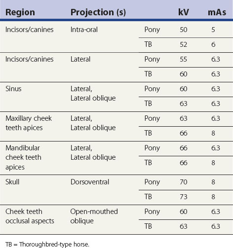
The choice of exposure factors depends on the output of the X-ray machine and speed of the imaging system in use.1 Table 13.1 gives examples of exposures suitable for obtaining dental and sinus radiographs.
Table 13.1 Suggested exposures for various radiographic projections of the equine skull. Exposures have to be altered for different X-ray machines, different film-screen combinations, and varying size of patient
Accessory equipment
Grids
The use of grids is discouraged for standing radiography as they are not required for obtaining high quality radiographs, because the amount of scattered radiation is usually minimal, and their use increases the risk of radiation exposure to personnel. Additionally, for oblique views, it may be difficult to accurately align and center the X-ray beam with the grid, which may result in image artefacts.
Cassette holders
The use of cassette holders is essential in order to minimize exposure of personnel to the primary beam, and holding cassettes by hand should be considered unacceptable. A flexible and readily adjustable system is required to allow radiography of different sized horses and varying resting head positions. This is most easily achieved using a long-handled cassette holder, which can be constructed from wood or aluminum, with a handle up to 2 m long and which can be adjusted to different heights and varying angulations (Fig. 13.1). Alternatively, vertical suspension systems linked to the X-ray tube are also suitable for lateral or latero-oblique radiographic views, as is simply suspending the cassette in a fabric bag (e.g., pillowcase) hanging from a mobile (e.g., drip) stand. Long adjustable ties at each side of the bag allow varying heights and angles of the cassette to be obtained.1
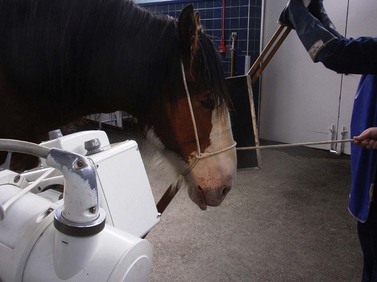
Fig. 13.1 Use of a long-handled cassette holder to increase the distance between personnel and the primary beam. Note the horse is wearing a rope headcollar.
Box 13.1
Practical tips for dental/skull radiography
• Using a large cassette and collimating the primary beam to include a large area, e.g., the entire maxillary cheek teeth row and sinuses if a maxillary dental disorder is suspected, can make interpretation of skull radiographs easier as abnormalities can be related to easily identifiable anatomical structures
• Resting the nose of a deeply sedated horse on a stool or headstand may help to reduce swaying movements of the head
• Attaching the cassette directly to the head using bungee type elastic cords is an alternative way to prevent movement blur and removes the need for a second person to hold the cassette holder
• Using a lower exposure to view the paranasal sinus contents, incisors or wolf teeth, as compared with the relatively radio-opaque cheek teeth
• Using a small radio-opaque marker taped on an area of facial swelling or a blunt probe passed into a draining tract can provide invaluable information regarding the significance of radiological findings (see ‘Contrast studies’)
• Radiograph the contralateral (unaffected) cheek teeth row if you have difficulty deciding if a suspected abnormality is pathological or physiological (see ‘Normal radiographic anatomy’)
Radiographic projections
Introduction
Indications for equine dental radiography are numerous but most commonly include clinical signs associated with periapical dental disease, including disorders of the paranasal sinuses or nasal cavities (unilateral nasal discharge, facial or mandibular swellings, quidding, discharging sinus tracts), head trauma, developmental abnormalities, or periodontal disease. Various radiographic projections and techniques have been reported,1–7 but the ‘standard’ set of radiographs required to investigate a clinical case depends on the individual case presentation, clinician preference, and hospital protocols. In the author’s (SB) hospital, lateral, lateral oblique and dorsoventral radiographs are considered standard for investigation of a horse with suspected maxillary cheek tooth periapical infection and concurrent sinusitis. For suspected mandibular cheek tooth periapical infection, a lateral oblique view, plus the same view with a radio-opaque marker placed on the clinical area of interest (swelling or draining tract), usually suffices. In some cases, additional views, such as open-mouthed, intra-oral, or lesion-orientated obliques are useful. Practical tips for dental/skull radiography are given in Box 13.1.
Incisors and canines
Intra-oral radiographs (Fig 13.2)
The smallest cassette available should be used, and the patient must be sedated to prevent damage to the cassette. A low exposure is required compared with that needed to image the cheek teeth. The cassette should be placed between the incisors, as far caudally as possible, and held in position using long-handled hoof trimmer testers or a similar instrument, with the cassette held at a distance from the assistant.1 The X-ray beam is directed at 60–80° from the dorsal plane (which runs parallel to the hard palate), depending on the conformation of the incisors, using a rostrodorsal–caudoventral oblique to image the maxillary incisors/canines and a rostroventral–caudodorsal oblique to image the mandibular incisors/canines. The beam should be centered on the Triadan 01s (central incisors), and collimation should include the rostral and lateral aspects of the lips. If necessary, the X–ray beam can also be angulated slightly from left to right to try and highlight the apices of incisors at the edges of the incisor arcade without superimposition of adjacent teeth (Figs 13.3 & 13.4).
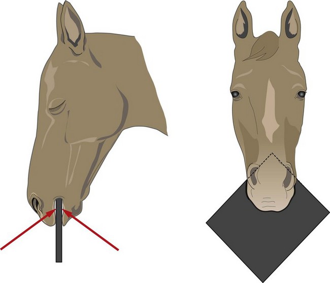
Fig. 13.2 Cassette and X-ray beam positioning for intra-oral projections of the incisors and canine teeth.
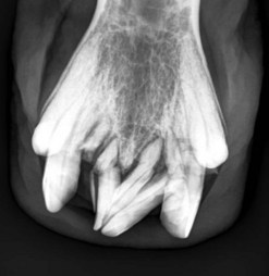
Fig. 13.3 Intra-oral view of the lower incisors of a horse with abnormally small and fractured 01s and 02s. This radiograph was taken with the X-ray beam perpendicular to the frontal plane. Note there is superimposition of the apices of the 02s, 03s and canines.
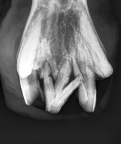
Fig. 13.4 Intra-oral view of the same horse as in Fig. 13.3. The radiograph is taken at a slight angle (25°) to the frontal plane from left to right. Note that on the right side of the radiograph, the apices of 302 and 303 are no longer superimposed.
Lateral projections
These radiographs are occasionally indicated, although the superimposition of incisors of the right and left sides usually makes individual incisors impossible to distinguish. They can be useful for identification and orientation of dysplastic or retained incisors or for assessment of fractures of the premaxilla or rostral mandible. Adding a slight (5–10°) rostrocaudal angulation to a lateral radiograph centered on the canines can provide separation of left and right sides and allow examination of individual reserve crowns and apices of these teeth.
Canines and wolf teeth
Lateral oblique projections
All or part of the canines may be visible on intra-oral films (see previous section), but in many horses the reserve crown and roots of the canines, as well as the wolf teeth (Triadan 05s, 1st premolars), are best imaged using a lateral projection of the rostral skull with a small amount (15–20°) of either rostrocaudal or dorsoventral angulation of the X-ray beam. The angulation prevents superimposition of the contralateral tooth.
Cheek teeth
Lateral projection (Figs 13.5–13.7)
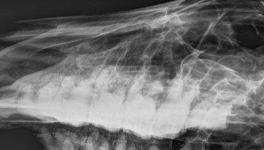
The lateral view is useful to visualize fluid lines and abnormalities of the maxillary or frontal bones or within the paranasal sinuses because the anatomy of the sinuses is not distorted by obliquity of the X-ray beam. The major disadvantage of the lateral view is that lesions cannot be localized to the left or right sides because both sides are superimposed. For this same reason, individual cheek teeth apices cannot be evaluated using this view.
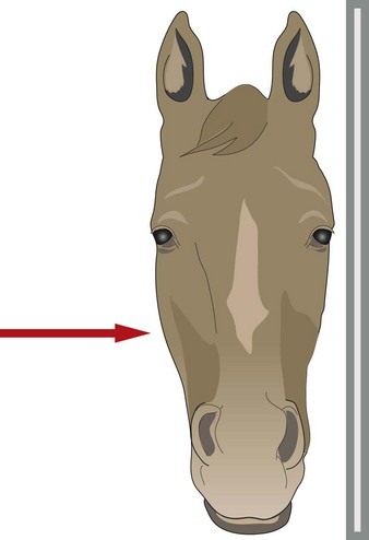
Fig. 13.5 Direction of the X-ray beam (arrow) and cassette position for lateral projections of the skull.
The horse should be positioned with the lesion side adjacent to the cassette. The cassette should be held in the cassette holder in a vertical plane, parallel with the dorsal contour of the head, and as close to the head as possible. The primary beam should be horizontal and perpendicular to the long axis of the head. The primary beam should be collimated to reduce scatter, and rotating the light beam diaphragm unit to align it with the orientation of the horse’s skull helps to keep the collimation tight.
For maxillary cheek teeth, the beam should be centered just dorsal to the rostral aspect of the facial crest if the cheek teeth and/or paranasal sinuses are being examined. The entire facial area should be included to ensure that the entire maxillary cheek teeth row and all the paranasal sinuses are included in the radiograph. Hence, topographic markers for collimation include: the caudal aspect of the diastema (‘bars of mouth’) rostrally, the eye caudally, and the dorsal aspect of the skull (Fig. 13.6).
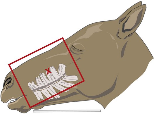
Fig. 13.6 Centering point (red cross) just dorsal to the rostral aspect of the facial crest and collimation (red outline) for lateral and lateral oblique radiographs of the maxillary cheek teeth and paranasal sinuses.
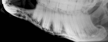
Lateral views of the mandibular cheek teeth are less frequently indicated, but the beam should be centered over the area of interest (usually indicated by a discharging tract or mandibular swelling), and rostrocaudal collimation should be adjusted to include the entire cheek teeth row, if possible. The thick masseter and pterygoideus muscles overlie the caudal three mandibular cheek teeth (Fig. 13.7), and hence higher exposures are required to image the apices of these teeth as compared to the rostral mandibular cheek teeth.
Latero30°dorsal–lateroventral oblique projection (Figs 13.8–13.9)
This view separates structures on the left and right sides of the skull so that they are not superimposed on each other. It gives the clearest view of the apices of individual maxillary cheek teeth and can help to localize sinus lesions to the left or right sides if this is not clinically obvious. A higher exposure should be used to radiograph the radio-opaque cheek teeth as compared to the relatively radiolucent sinus contents.
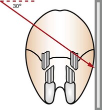
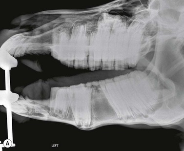
Fig. 13.8 Diagram showing direction of the X-ray beam (arrow) and cassette position for latero30°dorsal-lateroventral oblique radiograph of the maxillary cheek teeth apices.
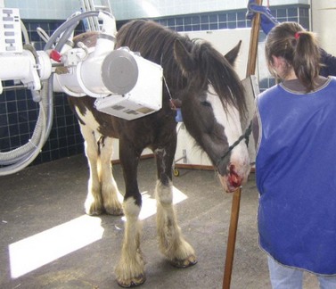
Fig. 13.9 Radiographic positioning to obtain a latero30°dorsal-lateroventral oblique radiograph of the maxillary cheek teeth apices.
Disadvantages of the oblique view are that it can be more difficult to consistently obtain good quality oblique radiographs, because the angulation of the standing sedated horse’s head is usually somewhere between vertical and horizontal, making it difficult to direct the X-ray beam accurately. As noted, having an X-ray machine that can be moved in three dimensions helps enormously when obtaining these views. It should be noted that fluid lines in the sinuses are often not apparent in oblique views, being replaced with indistinct soft tissue opacity. Additionally, it can be more difficult to localize abnormalities to specific sinuses due to superimposition of some structures e.g., the dorsal aspect of the caudal maxillary sinus and the dorsal-conchal sinus are often superimposed.
The standing horse should be positioned so that the lesion side is next to the cassette, which is held in the cassette holder in a vertical plane, close to the horse’s head. The primary beam should be angled latero30°dorsal-lateroventral (i.e., at 30° from the dorsal plane, which runs parallel to the hard palate) and centered 3–5 cm dorsal to the rostral aspect of the facial crest (Fig. 13.6).
The primary beam should be collimated to reduce scatter (as for the straight lateral view) and should include the entire maxillary cheek teeth row and the paranasal sinuses. Inadvertent rostrocaudal angulation of the X-ray beam is a common fault and should be avoided if possible. Excessive rostrocaudal (or dorsoventral) angulation distorts anatomical structures, particularly the apices of the cheek teeth, making them difficult to evaluate accurately.
For anesthetized horses, which are usually positioned in lateral recumbency with the affected side uppermost (to allow access for surgery), the cassette is placed beneath the horse’s head, i.e., next to the unaffected side, rather than next to the affected side as is the case for standing horses. Therefore the angle of the X–ray beam must be reversed (compared to the standing horse) to obtain oblique projections of the cheek teeth or sinuses, e.g., for maxillary cheek teeth apices with the affected side uppermost, a ventrolateral to dorsolateral beam direction is required (Fig. 13.10). This projection creates more magnification of the image but should not have a deleterious effect on surgical decision-making unless measurements for surgical implants (e.g., dynamic compression plates) are being made. In such cases, placing a metal marker of known size in the region of interest allows for calculation of the degree of magnification and subsequent correction.
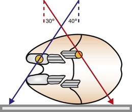
Fig. 13.10 Lateral oblique radiographic projections of the maxillary (red arrow) and mandibular (blue arrow) cheek tooth apices in an anesthetized, laterally recumbent horse undergoing surgery. The affected side is placed uppermost to allow surgical access to the lesion (orange circles), and the cassette is placed underneath the head. The X-ray beam must be directed in the opposite direction to conventional views, and more magnification of the image results.
Latero35–45°ventral–laterodorsal oblique projections (Fig. 13.11)
This view is used to separate the left and right hemimandibles and mandibular cheek teeth apices in order to view the affected side without superimposition of the contralateral hemimandible. As previously noted, a higher exposure is required when imaging the caudal three cheek teeth because of the overlying thick masseter and pterygoideus muscles (Fig. 13.7). Additionally, a higher angle is usually required for radiography of the caudal cheek teeth apices because these are positioned more dorsally within the mandibular bone. For the same reason, the cheek teeth of old horses with short reserve crowns also need to be radiographed using a higher angle.
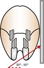
Fig. 13.11 Positioning of cassette and angle of X-ray beam to obtain a latero35–45° ventral–laterodorsal oblique radiograph of the mandibular cortex and cheek teeth apices.
Similar to the latero30°dorsal–lateroventral oblique view, inadvertent rostrocaudal angulation of the X-ray beam is a common fault with this view of the mandible, and should be avoided, if possible, because excessive rostrocaudal angulation distorts anatomical structures, particularly the apices of the cheek teeth, making them difficult to evaluate accurately. The minimum dorsoventral angle of X-ray beam which clearly separates the left and right cheek teeth apices should be used. Using a very large oblique angle gives better separation of the cheek teeth rows and allows visualization of more reserve crown, but also causes artefactual distortion of the apices.
The standing horse should be positioned so that the lesion side is closest to the cassette, which is held in the cassette holder in a vertical plane. The primary beam should be angled 35–45° lateroventral-laterodorsal (angled up from the dorsal plane which runs parallel with the hard palate) and centered at the area of interest, such as a mandibular swelling or cutaneous discharging tract – whose presence is the usual indication for taking this radiographic view. The primary beam should be collimated to reduce scatter but should include the ventral mandibular cortex and the entire cheek teeth row, if possible.
For anesthetized horses, which are usually positioned in lateral recumbency with the affected side uppermost (to allow access for surgery), the cassette is placed beneath the horse’s head i.e., next to the unaffected side, and the direction of the X-ray beam is reversed (Fig. 13.10).
Dorsoventral projection (Figs 13.12–13.13)
This view is quite easy to obtain in the sedated horse and is particularly useful for visualizing the ventral conchal sinus, nasal cavities, and nasal septum. Additionally, it can be used for evaluating maxillary/mandibular fractures; bony distortion of the maxilla associated with periapical infection of the rostral cheek teeth or intra-sinus masses. Laterally or medially displaced teeth and fractured maxillary teeth (particularly sagittal fractures) can also be visualized with this view; however, these abnormalities should be apparent during a thorough oral examination. The extremely dense bone of the hemimandibles makes it almost impossible to evaluate normally positioned mandibular cheek teeth using this projection.
An increased exposure is required for this projection compared to those used for lateral or lateral-oblique views of the skull. The X-ray beam is directed perpendicular to the dorsal plane of the head (which runs parallel to the hard palate) with the cassette held parallel with the ventral mandible and positioned as caudally as possible (Fig. 13.12). Because the mandibular cheek teeth rows are so close together (anisognathia), even a small degree of obliquity obscures one nasal cavity, ventral conchal sinus, and maxillary cheek teeth row and prevents accurate comparison of left and right maxillary sinus opacity; therefore, great care must be taken to ensure that the head is absolutely straight and the beam perpendicular to the dorsal plane. The centering point is in the midline of the dorsal aspect of the head at the level of the rostral aspect of the facial crests. Collimation of the primary beam should include the left and right lateral extents of the skull, the caudal aspects of the bony orbits and the diastemata, rostrally (Fig. 13.13).
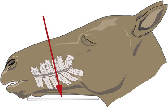
Fig. 13.12 Diagram showing cassette position and angle of the X-ray beam for obtaining a dorsoventral radiograph of the skull.
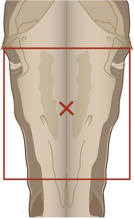
Fig. 13.13 Diagram showing area of collimation and centering point (cross, at the level of the rostral aspect of the facial crests) for dorsoventral radiographs of the skull.
In the anesthetized horse, ventrodorsal radiographs can be obtained with the horse positioned in dorsal recumbency and the head and neck fully extended. Ideally, the endotracheal tube should be removed to prevent its superimposition on the nasal cavities and conchal sinuses.
Dorsoventral projection with offset mandible
This radiographic projection is uncommonly indicated, but gives a clearer unilateral view of the medial aspect of one row of maxillary cheek teeth and the nasal cavity/conchal sinus immediately axial to them. It has been suggested that this projection is particularly useful for demonstrating subtle alveolar disease and maxillary osteitis.1 A rope is placed around the interdental space, and the mandible is displaced to the contralateral side by an assistant pulling on this rope. A dorsoventral projection is then obtained as described above.
Open-mouthed oblique projections (Figs 13.14–13.18)
This radiographic view is used to image the erupted crowns of the cheek teeth and the occlusal aspect of the alveolus (alveolar crest).6 Disorders of the erupted crown such as diastemata, clinical crown fractures, and abnormalities of wear can be imaged.6 The patient must be sedated so that it accepts a Butler’s gag placed between its incisors (Fig. 13.14). Alternatively a short length of hollow PVC tubing or a block of wood can be used to separate the incisors and thus the occlusal aspects of the cheek teeth.
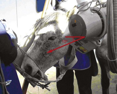
Fig. 13.14 Photograph showing sedated patient with a Butler’s gag separating the incisors to allow an open-mouthed oblique dental radiograph to be obtained.
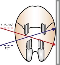
Fig. 13.15 Diagram showing angle of incidence of the X-ray beam to obtain open-mouthed oblique views of the maxillary (blue arrow) and mandibular (red arrow) erupted crowns. The affected side is nearest to the cassette.
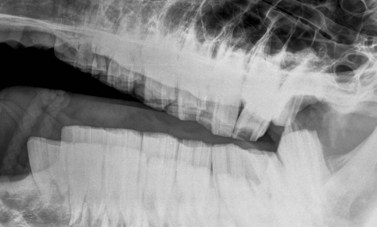
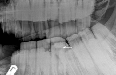
Fig. 13.16 Latero10°ventral-laterodorsal open-mouthed oblique view of an aged horse with a supernumerary mandibular cheek tooth (Triadan 12). Note the large overgrowths present on this supernumerary tooth and the excessive wear of the corresponding upper 11.
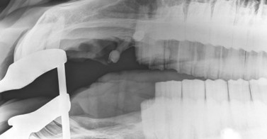
Fig. 13.17 Open-mouthed oblique view centered on the 05s (wolf teeth) showing large, rostrally displaced and abnormally angulated upper 05s with long thin roots. The Butler’s gag is separating the incisors.
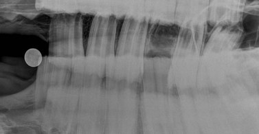
Fig. 13.18 Latero30°ventral-laterodorsal open-mouthed oblique view of a horse immediately after 09 dental extraction. The contents of the mid and more occlusal aspects of the empty alveolus can be visualized without superimposition from cheek teeth of the contralateral row.
The cassette is positioned vertically on the lesion side, close to horse’s head. For these open-mouth views, the X-ray beam is directed in the opposite direction to conventional (closed mouth) oblique views i.e., a dorsolateral–ventrolateral to image the mandibular erupted crowns or a ventrolateral–dorsolateral to image the maxillary erupted crowns. Additionally, the angle of incidence of the X-ray beam is reduced compared to conventional oblique views: latero10°dorsal–lateroventral (ventrally) for mandibular cheek teeth, latero15°ventral–laterodorsal (dorsally) for maxillary cheek teeth. The primary beam should be centered on the rostral aspect of the facial crest and collimated to include all the erupted crowns in the cheek teeth row (Fig. 13.16).
To image the full length of the cheek teeth reserve crowns, open-mouthed oblique projections using approximately the same angles as for standard closed-mouth views may be used, although to prevent superimposition of the contralateral maxillary arcade completely, laterodorsal angles slightly greater than 30° may be required. These projections are also often helpful for examining alveoli for possible dental fragments after dental repulsion (Fig. 13.18). Open-mouthed oblique projections are also useful for imaging the Triadan 05s (wolf teeth) (Fig. 13.17).
Intra-oral oblique projections (Figs 13.19–13.20)
These projections, where a flexible film package or cassette is placed into the oral cavity, represent a modification of the bisecting angle technique used widely in human dental imaging. They have the advantages that there is no superimposition of structures from the contralateral side of the skull, and can also give good detail of the interdental bone and alveolar crest region. However, in the author’s experience, these projections can be difficult to obtain in standing sedated horses, due to difficulties keeping the film in place within the oral cavity.
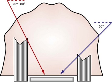
Fig. 13.19 Diagram showing intra-oral position of the cassette and angles of incidence of the X-ray beam to obtain intra-oral cheek teeth radiographs of young horses with long reserve crowns (left) and older horses (right).
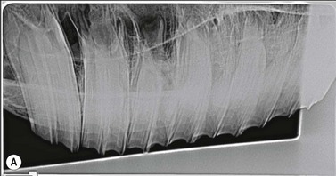
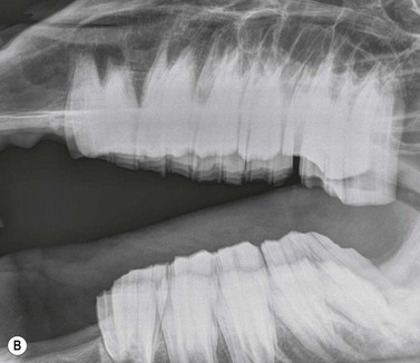
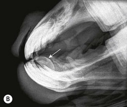
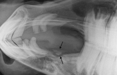
Fig. 13.20 (A) Intra-oral radiograph of a maxillary cheek teeth row.
Radiograph courtesy of J. Easley.
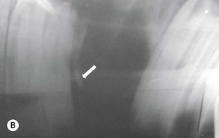
(B) Intra-oral radiograph taken intra-operatively during a dental extraction procedure. A small bone-opacity fragment can be seen in the rostral aspect of the alveolus (arrow).
(Radiograph courtesy of W.H. Tremaine.)
The use of human dental film packs4 or of improvised cassettes made of vinyl7 or heavy-duty black polythene1 has been described for intra-oral projections in horses. Pre-packed human dental film is often only large enough to image one or two cheek teeth on each radiograph, and this is a major disadvantage, particularly because the affected tooth is not commonly identified prior to the radiographic examination. Improvised cassettes can be made into a suitable shape for the equine oral cavity (circa 10 × 25 cm) by cutting down film and card-mounted intensifying screen(s) before double wrapping them in closely fitting, light-proof bags e.g., of heavy-duty black polythene, and sealing the edges with light-proof adhesive tape.1 The disadvantages of this system include the time taken to prepare the above materials, poor film/screen contact and the need for wet processing of films.
A self-retaining, full-mouth speculum is used to open the mouth of the heavily sedated or anesthetized horse, and the film is placed in the oral cavity, parallel to the hard palate (Fig. 13.19). If using a small sized film, it must be placed at the level of the tooth of interest. For teeth of mature or older horses, the X-ray beam is directed at an angle of 50°–60° to the horizontal, but to examine the longer reserve crowns of young horses, increased incident angles (70°–80°) are required (Fig. 13.19). The centering point is somewhere between the level of the facial crest and up to 6 cm dorsal to the facial crest, depending on the length of the tooth being radiographed i.e., in younger horses, a more dorsal centering point is required compared to aged horses with short reserve crowns.
Contrast studies
Placement of a radio-opaque marker over an area of facial swelling and repetition of a radiographic projection (Fig. 13.21) can be an invaluable aid when assessing the clinical significance of radiographic changes. If a cutaneous draining tract is present, as is common in cases of periapical infection of the mandibular cheek teeth or upper 06s and 07s, a blunt metallic probe can be placed into the tract, held in place with tape (Fig. 13.22) and a repeat radiograph taken (Fig. 13.23). This very simple form of contrast study often provides unequivocal evidence that a tooth is infected.
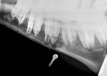
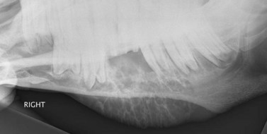
Fig. 13.21 Lateral oblique radiograph of the hemimandible of a horse which presented with a swelling on the ventral aspect of its mandible. A radio-opaque marker has been taped to the area of maximal facial swelling, which corresponds to an area of clubbing (short, rounded appearance) of the caudal root of the 08 due to loss of the apex of that root and surrounding radiolucency.
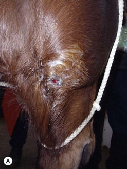
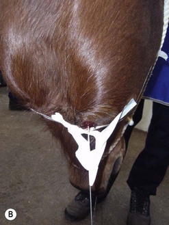
Fig. 13.22 (A & B) A blunt metallic probe placed into a cutaneous discharging tract and secured with radiolucent tape can provide strong evidence as to which tooth is infected in cases of suspected periapical infection.
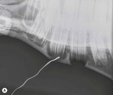
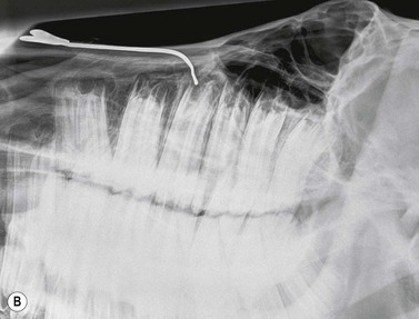
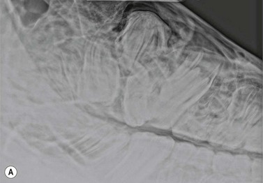
Fig. 13.23 Lateral oblique radiographs with a blunt metallic probe in place in cases of periapical infection with discharging cutaneous tracts involving the mandibular (A) and rostral maxillary (B) cheek teeth.
Water soluble iodinated contrast media may also be introduced into a tract i.e., fistulography. To avoid leakage, injection should be made through a self-retaining catheter with an inflatable bulb (e.g., Foley) and discontinued immediately resistance is felt.1
Normal radiographic anatomy
Deciduous dentition
Deciduous incisors are more radiolucent, have shorter reserve crowns and roots, and have a smaller cross-sectional area than their permanent counterparts (Fig. 13.24). Deciduous canines (if present) are vestigial, spicule-like structures that do not erupt above gum level, but which are occasionally evident radiographically.
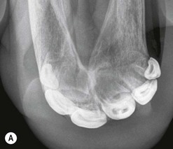
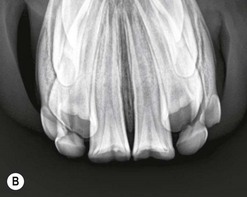
Fig. 13.24 Intra-oral radiographs of the mandibular incisors of: (A) a yearling with a fractured mandible (note the obliquity of the left incisors compared to the right). The developing buds of the permanent 301 and 401 can be seen mesial to the 701 and 801. (B) A 3-year-old horse. The 301 and 401 (central incisors) are erupted but the deciduous lower 02s and 03s remain in wear. Note the canines are superimposed on the developing permanent 03s.
Linear, radio-opaque enamel folds may be seen within the developing deciduous cheek teeth of the fetus, and soon after birth foals should have 12 deciduous cheek teeth present in the oral cavity. These teeth have short, spicular roots (Fig. 13.25) and can be distinguished from developing permanent premolars by their greater mineral content and relative lack of internal structure.1 As the germs of the permanent cheek teeth develop beneath the deciduous cheek teeth (Fig. 13.26), they cause resorption of the apices of their overlying deciduous counterparts.8
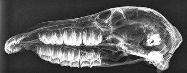
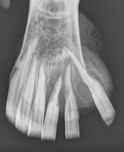
Fig. 13.25 Lateral oblique view of a foal’s skull. Note the short spicular roots of the 3 deciduous cheek teeth in each row. The dental buds of the permanent cheek teeth are not apparent yet.
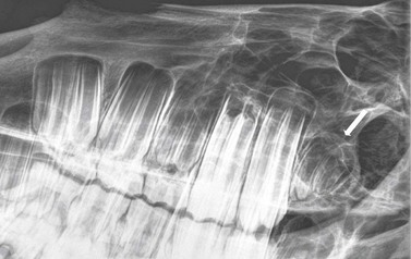
Fig. 13.26 Lateral oblique radiograph of the maxillary cheek teeth of a 2-year-old horse. The 09 has erupted and is in wear, and the 10 is just erupting. The dental buds of the permanent 06, 07, and 08 can be seen developing dorsal to their deciduous counterparts, with the deciduous 06 about to be shed. The dental bud of the 11 (arrow) is developing at the caudal aspect of the maxilla.
Permanent dentition
Incisors, canines and wolf teeth
The reserve crowns and apices of the permanent incisors converge towards each other on an intra-oral radiographic projection, and there may be partial superimposition of the reserve crowns and roots of the Triadan 02s and 03s (middle and corner incisors) on a true dorsoventral radiograph (Fig. 13.27). If the roots and reserve crowns of these teeth are to be examined in detail, a slight angulation of the X-ray beam can be used to prevent this superimposition (Fig. 13.4). The incisor teeth gradually change their angle throughout life, the occlusal angles changing from almost vertical in a young horse to an increasing angle of incidence, and the occlusal surface becomes more triangular in cross section with advancing age. In recently erupted incisors, the infundibula can be recognized on the obliquely projected occlusal surfaces and in those that have been longer in wear, traces of infundibular enamel and cement may be visible as thin, elliptical conical radiodense shadows.1 The pulp cavities of the incisors should be evident as curvilinear radiolucent structures in the middle of these teeth.
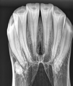
Fig. 13.27 Intra-oral radiograph of the rostral mandible of a teenage horse. Note the triangular cross section of the occlusal surfaces of the 01s and 02s (central and middle incisors) as compared to those of a young horse (Fig. 13.24). There is a vestigial dental remnant lying just caudal to 303.
The canine teeth, and particularly the lower canines, are positioned in close proximity to the 03s (Fig. 13.24B) and it may be difficult to clearly delineate the roots and reserve crowns of the canines due to superimposition of the roots and reserve crowns of the 03s (the corner incisors) in some horses. Small unerupted canines may be present below the gingiva in mares. If present, the 05s (‘wolf teeth’, Fig. 13.18) are normally situated immediately rostral to the 06s (1st cheek tooth). Up to 4 wolf teeth may be present; however, mandibular 05s are very rare. Wolf teeth may vary markedly in the size of their clinical crown, and the roots of these brachydont teeth can vary from a few mm to >2 cm in length. In a survey of radiographs of 134 horses, wolf teeth were present in 30 % of horses, but this may not be a true reflection of their incidence due to the common practice of ‘prophylactic’ or ‘therapeutic’ removal.9
Cheek teeth
The radiographic appearance of equine cheek teeth, and particularly their apices, varies markedly with age, and between individual cheek teeth positions. Consequently an appreciation of normal radiographic variation is required to enable proper interpretation of dental radiographs. Most apical infections occur in young horses where there can be marked differences in the radiographic appearance of the apical areas of normal adjacent teeth, and where immature apices with eruption cysts can radiographically resemble apical infections.
Enamel, dentin, and cementum (along with bone) are the densest materials in the body, and therefore the cheek teeth appear as very radio-opaque structures, within which the radiolucent pulp horns may be seen running longitudinally. Dentin and cementum have a lower proportion of mineral content than enamel and have a radio-opacity similar to bone.2 Younger cheek teeth contain little dentin relative to aged cheek teeth, and are, therefore, comparatively radiolucent.2 The reserve crown of the cheek teeth is attached to the alveolar bone by the periodontal ligament, which is evident radiographically as a narrow parallel radiolucent line between the tooth and the alveolus (Fig. 13.28). This space lies adjacent to a radiodense rim of cortical alveolar bone, radiographically, termed the lamina dura, which lines the alveolus (Fig. 13-28). Although disruption of this structure can occur with dental disease, the irregular contour of equine cheek teeth means that the lamina dura may not be visible on some radiographic projections of normal teeth, and (in contrast to brachydont radiographs) absence or partial discontinuity of the lamina dura is not a reliable indicator of apical or periodontal disease.9,10 The area of the periodontal ligament may widen due to disease processes, but the apices of young equine cheek teeth also have wider radiolucent areas adjacent to the lamina dura in the area of the eruption cysts (Fig. 13.29).
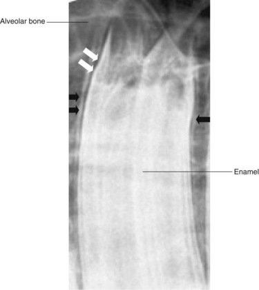
Fig. 13.28 Close up X-ray of a maxillary cheek tooth. The lamina dura (black arrows) is a linear radio-opacity that lines the alveolus. Note that the lamina dura denta is not visible along the entire contour of this normal tooth. The periodontal ligament (white arrows) is represented by a radiolucent area between the lamina dura and the periphery of the tooth.
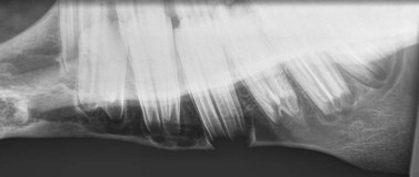
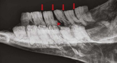
Fig. 13.29 Lateral oblique radiograph of the hemimandible of a normal 3-year-old horse. Note the wide, rounded, radiolucent periapical regions of the 07 and 08 which are termed ‘eruption cysts’. The ventral cortex of the mandible beneath the 08 is convex and extremely thin and appears radiolucent.
The dental buds of the permanent cheek teeth in the young horse are large, rounded, radiolucent structures, with a striated, vertical radiodense pattern, which is due to partially calcified enamel folds (Fig. 13.26). As a dental bud develops into a cheek tooth, its apical aspect appears as a round, radiolucent area with a very wide periodontal space, which is termed an eruption cyst. The lamina dura is often not visible around the apices of developing teeth. The permanent equine CT erupt between 1 and 4 years of age (see Ch. 5). Between 2 and 4 years of age (Fig. 13.29), the reserve crown is very long, and many of the cheek teeth still have large eruption cysts. At this age, the ventral border of the mandible becomes convex in some breeds (‘3- and 4-year-old bumps’) to accommodate these large dental structures, and the ventral mandibular cortex beneath the eruption cysts is very thin or even appears fully eroded. This convex appearance is lost as the horse ages due to continued eruption of the reserve crown, maturation of the cheek teeth apices, and remodelling of the mandibular cortex.
As the horse ages and the cheek teeth erupt, the true roots (i.e., enamel-free areas) develop, and the apices change from being rounded to developing a number of pointed structures, i.e., true roots (Fig. 13.30). Bearing in mind that the equine cheek teeth erupt at different ages, it is normal for young horses to have adjacent cheek teeth with very radiographically variable apical areas (Fig. 13.29). For example, major differences are present between the apices of the 08s (3rd cheek teeth) and 09s (4th cheek teeth) in a 4-year-old horse, because the 09 is 3 years older than the 08. Consequently, caution must be exercised when comparing the radiographic appearances of adjacent cheek teeth apices in young horses.
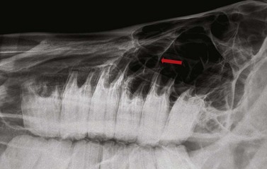
Fig. 13.30 Lateral oblique radiograph of the maxillary cheek teeth row of a 10-year-old horse. Note the pointed appearance of the apical areas which represents the development of ‘true’ roots. In this particular horse, the rostral root of the 08 is positioned rostral to the maxillary sinuses. Arrow = maxillary sinus septum.
The apices of some equine maxillary cheek teeth are positioned within the paranasal sinuses, and knowledge of this anatomic relationship is important in order to detect changes due to periapical infections (Fig. 13.31). Although there is some individual variation, generally the apices and reserve crown of the 06s and 07s and rostral aspect of the 08s (Fig. 13.30) lie within the radio-opaque, rostral aspect of the maxillary bone, and therefore, a slightly higher exposure is required to image these optimally. The caudal aspect of the maxillary 08s and all of the 09s are generally positioned within the rostral maxillary sinus, and the maxillary 10s and 11s lie within the caudal maxillary sinus (Fig. 13.31).
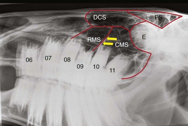
Fig. 13.31 Anatomy of the paranasal sinuses as viewed in a lateral radiograph. RMS, rostral maxillary sinus; CMS, caudal maxillary sinus; DCS, dorsal conchal sinus; FS, frontal sinus; E, ethmoturbinates; arrows, rostrolateral portion of the maxillary sinus septum. The 06 and 07 are positioned rostral to the paranasal sinuses.
The rostral and caudal maxillary sinuses are usually completely separated by a thin obliquely oriented bony septum which on lateral or lateral-oblique radiographs originates adjacent to the caudal aspect of the upper 09s, and courses from rostrolateral to caudomedial. Although the maxillary sinus septum is not always radiographically distinguishable from other intrasinus septae, its most lateral aspect is often represented by a linear radiopacity,11 extending dorsocaudally from the caudal aspect of the upper 09s (Fig 13.31). The position of the maxillary sinus septae may vary between right and left sides. The infra-orbital canals are radiographically apparent on lateral and lateral-oblique radiographs, lying directly dorsal to the apices of the caudal cheek teeth in young horses.
Due to the different times of eruption, the reserve crowns of the permanent cheek teeth are not all the same length – the 09s are consistently shortest, these being the first permanent cheek teeth to erupt. The 06s are also shorter and squarer shaped than the other cheek teeth.
As the horse ages, the reserve crown of the cheek teeth reduces in length as the tooth wears at its occlusal aspect and continues to erupt, despite cementum being increasingly laid down around the roots (Figs 13.32 & 13.33). This apical hypercementosis has the effect of obscuring some radiographic detail of the tooth roots, and making them appear thicker (clubbed) and more radiodense. Equine cheek teeth taper in towards their roots, and as the reserve crown length shortens, the rostrocaudal length of the erupted crown therefore decreases. Because the cheek teeth are no longer tightly apposed on the occlusal surface, aged horses are predisposed to developing (senile) cheek teeth diastemata (Fig. 13.33) and periodontal infection, due to food pocketing in these spaces.
Radiological interpretation
Sensitivity and specificity of radiography
When using a diagnostic test in practice, it is useful to know the sensitivity and specificity of that test. The sensitivity of a test represents the probability that the diagnostic test will be positive, given that the disorder is present. Specificity represents the probability that the test will be negative, given that the disorder is absent. Most studies published to date and outlined below have used film-based radiographic evaluation. It is likely that with the widespread use of digital and computed radiography in equine practice, our ability to radiographically detect dental abnormalities will be significantly improved.
Dental disorders
Radiographic changes consistent with periapical infection are most readily identified in the rostral maxillary equine cheek teeth whose apices lie rostral to the maxillary sinuses, and the mandibular cheek teeth, whose apices are contained within the mandible.9 In the more caudally positioned maxillary cheek teeth where secondary dental sinusitis is common, apical infections can be recognized with confidence in only 50–57 % of cases using radiography alone.9,12 Two more recent studies by Weller et al and Barakzai that have investigated the accuracy of radiography for diagnosis of equine dental disorders found radiographic sensitivities of 52 % and 69 % (respectively) and specificities of 95 % and 70 %.13,14 The differences between the results of these two studies are likely to be attributable to the different anatomical distribution of disorders in the two studies, with a considerably higher proportion of cases with dental sinusitis in the latter study as compared to predominantly mandibular or rostral maxillary dental lesions in the study performed by Weller et al (2001).13 A further study, using computed radiography,10 reported that periapical sclerosis, periapical lucency, and clubbing of tooth roots are the most reliable radiographic changes associated with periapical infection, but that mild changes in any of these categories are not dependable indicators of infection. This study also reported that loss of the lamina dura denta is a very insensitive (high number of false positives), but highly specific (low number of false negatives) indicator of periapical infection.
Paranasal sinus disorders
The sensitivity (85.2 %) and specificity (79.2 %) of radiography for detecting abnormalities of the equine sinuses have been shown to be moderate.15 The findings of Barakzai et al’s15 study are similar to the reported sensitivity (73–76 %) and specificity (79–80 %) of radiography for detecting acute sinusitis in human beings.16,17 It should be mentioned, however, that although radiography is a very useful tool for determining if sinusitis is present or not, establishing the cause of sinusitis can be considerably more difficult!
Abnormalities of development and eruption
Gross abnormalities of the erupted crown may be evaulated with a detailed oral examination; however, radiography is often useful in order to assess the structure of and location of the reserve crowns and apical areas.1 Many radiographs of these disorders are presented in Chapter 8.
Brachygnathia (parrot mouth, Fig. 13.34), prognathia (sow mouth) and wry nose
Radiography is not usually required to diagnose these developmental disorders of the premaxilla and/or mandible; however, the radiographic appearance of the teeth associated with these abnormalities has been illustrated in a review of congenital dental disorders18 and in Chapter 19.
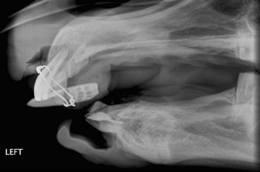
Fig. 13.34 Intra-operative lateral radiograph. This foal has suffered a rostral mandibular fracture with resultant mandibular shortening. The premaxilla has been fitted with a bite plate to allow some contact with the remaining lower incisors and so help prevent further ventral deviation of the premaxilla.
(Radiograph courtesy of P.M. Dixon.)
Oligodontia
The absence of a tooth or teeth due to failure of development of a tooth bud may result in abnormal occlusion and wear. This condition is common in miniature pony breeds (Fig. 13.35), and further images of this disorder are presented in Chapter 8.
Fig. 13.35 Oligodontia. The pony in (A) has anodontia of 308, 408 and 108, although the deciduous remnant (‘cap’) of one lower 08 is still present.
Radiograph courtesy of P.M. Dixon.
Polydontia
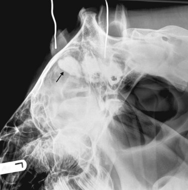
Extra, or supernumerary, teeth may have a normal anatomy or may be misshapen, malformed, and often misplaced (see Ch. 8). Due to their abnormal apical areas, it may be difficult to definitively ascertain if supernumerary teeth are apically infected or not. Quinn et al19 described a ‘domed soft-tissue opacity in the floor of the maxillary sinuses’ dorsal to the apices of supernumerary 12s (Fig. 13.36) to be a relatively consistent finding in affected horses. Supernumerary teeth can easily go unrecognized, particularly if the entire cheek tooth row is not included in the radiograph. Supernumerary cheek teeth are often very long, due to lack of attritional wear, and diastemata may develop between supernumerary and adjacent teeth.
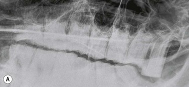
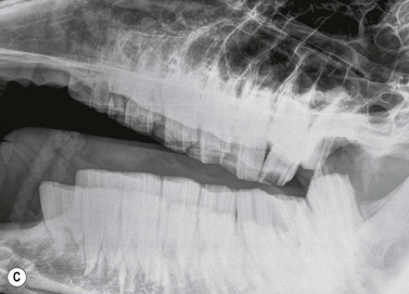
Fig. 13.36 Polydontia. Supernumerary maxillary cheek teeth (Triadan12s) are the most common supernumerary cheek teeth in horses. The 12 is usually markedly overgrown as in (A) but may be unerupted as in (B) if there is inadequate space (overcrowding). Note the abnormal shape of the apical area of the 112. (C) An example of overgrown bilateral supernumerary mandibular 12s.
Dysplastic teeth
Teeth with abnormal structure are relatively common in equidae (Fig. 13.37), and it can be difficult to ascertain whether such teeth are apically infected or not. They may be associated with abnormalities of eruption and dental impactions, and also with periodontal disease.
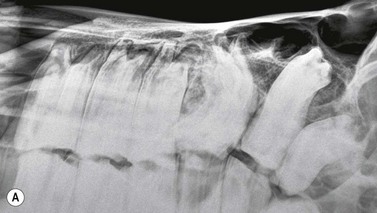
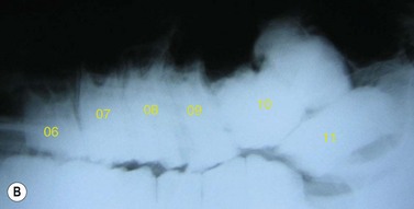
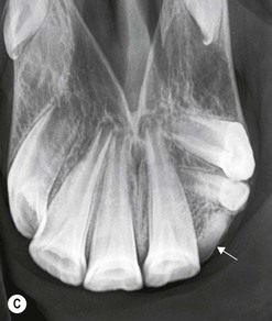
Fig. 13.37 (A) Maxillary cheek tooth row of a miniature Shetland pony with marked dysplasia of the 109, 110, and 111 and a corresponding wave mouth on the mandibular row. (B) Markedly enlarged, radiodense, dysplastic 110, which has displaced the reserve crowns and apices of 111 and 109 caudally and rostrally, respectively. (C) Abnormally small 302. The deciduous 702 remnant is retained (arrow).
Abnormalities of eruption
Disorders of eruption may affect the incisors (Fig. 13.38), canines, wolf teeth, or cheek teeth (Fig. 13.39) and are often predisposed to by dental impactions, and malformed or malpositioned teeth. Radiography is invaluable in assessing which teeth are involved, which, if any, are deciduous, which are permanent, and which teeth to extract in order to treat the disorder.
Temporal teratoma (Fig. 13.40)
The clinical signs of temporal teratoma (anomalous dental tissue in the parietotemporal region of the skull) are often pathognomic for this developmental disorder, but radiography can be very useful in order to confirm the diagnosis and evaluate the nature (whether or not it contains calcified dental structures), location, and size of the lesion prior to surgical excision.
Apical infection (Fig. 13.41)
Both clinical and radiographic signs of periapical (apical) infection are often specific to the tooth involved. For example, the apices of the maxillary 06s and 07s (and variably the 08s) and all the mandibular cheek teeth are contained within thick bone; hence, cases of periapical infection of these teeth typically present with facial swelling, which appears radiographically as bone lucency often surrounded by sclerosis and periosteal new bone formation, and also cutaneous draining tracts. The maxillary 08s–11s apices are contained within the maxillary sinuses; hence, horses with periapical infection of these teeth present clinically with nasal discharge and radiographically with changes associated with both dental infection and secondary sinusitis.
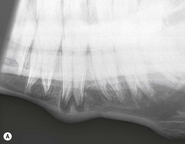
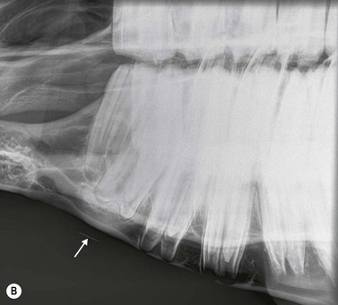
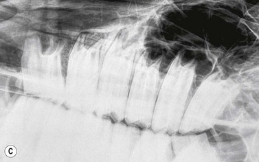
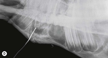
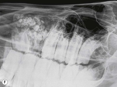
Fig. 13.41 Radiographic signs of periapical infection. (A) Radiolucent halos are evident around both roots of an infected 408, with widening of periodontal space, sclerosis of the ventral mandibular cortex and periosteal new bone deposition. (B) A zone of sclerosis is present around this infected 306. The affected apex is somewhat blunter than those of adjacent teeth; however, this can be a normal feature of 06s. An arrow points to a small radio-opaque marker placed on the skin at the site of facial swelling. (C) Infected 108. A periapical radiolucent halo surrounded by marked sclerosis is evident around the infected apex of this tooth, which lies outwith the rostral maxillary sinus in this horse. (D) Gross destruction of the architecture of this infected 407 dental bud is present, with loss of much of the apical aspect of its crown. Multiple radio-opaque fragments are present in the alveolus, which may represent dental fragments or cementoma formation. A draining tract (with probe inserted) and gross mandibular new bone formation are evident. (E) Marked sclerosis is present around an apically infected 210. This horse had concurrent sinusitis. (F) Massive reactive cementoma deposition is present around the apex of chronically infected 207. Dystrophic calcification of the nasal conchae is likely also contributing to the radio-opaque appearance in the area rostral to the alveolus of 207. Most of the reserve crown of this tooth was still present; however, it is quite radiolucent, due to demineralization caused by chronic infection.
Radiographic changes consistent with early periapical infection include widening of the periodontal space and focal loss or irregularity of the lamina dura. When periapical infection has been present for many weeks, the affected apex and adjacent alveolar bone develop lytic changes, especially in mature teeth where the true roots (non-enamel areas) are well formed, due to decalcification and/or destruction of dental and adjacent alveolar tissues. These changes manifest as periapical radiolucent ‘halos’, and with time, a rounded or ‘clubbed’ appearance of the tooth roots can develop due to gross lysis/destruction of the root structures. In more chronic periapical infection, a zone of radiodense sclerosis may surround the periapical ‘halo’, due to new bone deposition around the lytic infected dental/alveolar area. More marked sclerosis develops around the apices of the rostral maxillary and mandibular cheek teeth than around the apices of the caudal maxillary cheek teeth, because the apices of the former teeth are positioned in denser bone than those of the caudal maxillary cheek teeth, which are situated in only thin alveolar bone within the maxillary sinuses.
External draining tracts are common with mandibular cheek teeth periapical infections and sometimes occur with rostral maxillary cheek teeth infections. These tracts may be apparent radiographically if there is a zone of bony sclerosis around their margins, but otherwise cannot be identified on plain radiographs. Infections of the caudal maxillary cheek teeth rarely present with external draining tracts, but affected horses may rarely have cellulitis of the masseter or pterygoideus muscles. If an external sinus tract is present, a blunt, malleable metallic probe should be inserted into the tract, and an appropriate lateral-oblique radiograph taken (Fig. 13.41D). This procedure can provide irrefutable evidence of dental disease, identify the affected apical area of the tooth, and provide a landmark for placement and angulation of the dental punch, if tooth repulsion is to be performed. Longer standing mandibular cheek teeth infections often have gross new mandibular bone formation beneath the affected apex, making the hemimandible thickened on palpation.
Focal, soft-tissue radio-opacities may also be apparent in the sinuses if periapical infection of the caudal 3–4 maxillary cheek teeth has occurred. These opacities may be due to a rounded, (soft tissue) granuloma or later, an encapsulated abscess developing over the infected apex. Fluid lines may be apparent in straight lateral views of the sinuses, due to accumulation of liquid purulent material. In cases of dental sinusitis, as in other sinusitis cases, inflamed and hypertrophied sinus mucosa may cause increased soft-tissue opacity within the sinuses.9,12
In less destructive chronic periapical infections, reactive abnormal deposition of (radio-opaque) cementum may occur on the infected tooth apex in an attempt to help control the infection, often resulting in an increase in size and blunting of the apex. In more destructive chronic periapical infections, no such repair process occurs and progressive destruction of the infected apex results in initial radiolucency and then loss of the apex and adjacent reserve crown of the affected tooth (‘clubbing’). Dystrophic mineralization (‘coral formation’) of the cartilage of the nasal conchae may also occur with chronic maxillary cheek teeth periapical infections, particularly those involving the more rostrally positioned maxillary teeth.9,12
Periodontal disease
Oral examination is superior to radiography for the detection and investigation of periodontal disease, but open-mouthed, oblique or intra-oral radiographs may occasionally be useful for demonstrating the effects of severe periodontal disease on the alveolar crest (Fig. 13.33) and adjacent structures. Occasionally, very severe and deep periodontal disease may extend towards the apex of the tooth and may be the cause of periapical infection. Radiography may be used to outline the dimensions of diastemata and the angulation and distance between the cheek teeth. It may also provide additional information on displaced teeth, which usually have associated periodontal disease.
Odontogenic tumors
Tumors of dental-tissue origin are all rare, but may be more common in horses than in other species20 and are discussed in detail in Chapter 11. Five types of odontogenic tumors have been recorded in horses, and their radiological characteristics have been reviewed in detail.21 Ameloblastomas and ameloblastic odontomas can have a similar radiographic appearance.21 They are expansive, soft-tissue opacity masses containing lytic areas and sometimes areas of irregular granular calcification21 and often displace adjacent teeth (Fig. 13.42). Complex and compound odontomas are irregular, tumor-like masses of dental tissues in well differentiated forms (Fig. 13.43). Complex odontomas contain all the elements of a normal tooth but within a disorganized structure, hence radiologically they appear as multiple, small, lobulated radio-opaque masses within a well-defined cyst-like structure.20,21 In contrast, compound odontomas contain an orderly pattern of dental tissues which form recognizable tooth-like structures. Cementomas are very radio-opaque mineralized structures, often rounded in appearance and associated with chronically infected tooth apices (Fig. 13.41F) or their alveoli following extraction of the infected tooth.
Other tumors and cystic structures affecting dentition
Any tumor or other space-occupying lesion affecting the mandible, incisive bone, maxilla, or paranasal sinuses may affect the teeth by displacing them or destroying their architecture, often through pressure resorption. Osteoma, osteosarcoma, osteoblastoma, chondrosarcoma, and fibrosarcoma are all tumors of bone that can arise in the regions of the equine jaws, and in the mandible in particular.22 It can be very difficult to differentiate between these individual tumor types radiographically, with proliferation of a bone-opacity mass being the most common radiologic presentation. Osteosarcomas may have a characteristic ‘sun-burst’ appearance of bone lysis and irregular, radiant deposition of reactive new trabecular bone. Other tumors of soft-tissue or mixed soft-tissue/bone origin, such as ossifying fibroma, fibrous dysplasia, and squamous cell carcinoma (Fig. 13.44) can have similar radiographic appearances to bony tumors as they often replace bone with fibro-osseous tissue. In their earlier stages, localized swellings caused by malignant tumors may be clinically similar to those caused by dental periapical infection, and consequently, the radiographic demonstration of bone destruction in the presence of normal dental apices may be an important differentiating feature of jaw tumors.1 Cyst-like lesions of the mandible and paranasal sinuses of horses are commonly reported, and may displace the teeth due to their expansile effects.23
Traumatic dental injuries
Horses with skull and in particular, mandibular fractures often have dental injuries, and radiography, along with detailed oral examination, is useful in evaluating such cases (Fig. 13. 45). Fractures of the rostral mandible and premaxillary (incisive) bone occur frequently in young horses (Fig. 13.24A) and radiography may demonstrate whether temporary, permanent or both types of dentition have been damaged. Fractures of the cheek teeth also commonly occur alongside traumatic damage to the mid- and caudal mandible; however, even if identified acutely, treatment of dental fractures beyond removal of palpably loose fragments is usually best left until the supporting bone is healed as some fractured teeth can survive the acute pulpitis and do not become chronically infected.
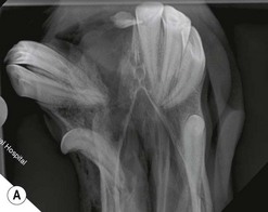
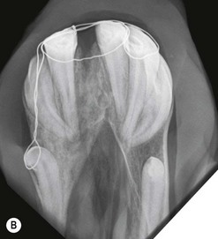
Fig. 13.45 (A) Pre- and (B) 6-week postoperative intra-oral radiographs of a horse with a complete, comminuted, displaced fracture of the pre-maxilla, with loss of one central incisor.
Fractures of the erupted crown are more likely to be pathological (idiopathic cheek teeth fractures – see Ch. 10) or iatrogenic than traumatic in etiology, and these fractures are best imaged using an open-mouthed, oblique radiographic projection (Fig. 13.46). Imaging their apices is often also worthwhile.
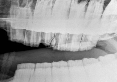
Fig. 13.46 Open-mouthed oblique radiograph of a horse with a fractured erupted crown of 108. A fragment is missing rostrally, and a displaced caudal fragment is still in place.
Bitting injuries commonly involve the physiological diastema (interdental space; between the incisors and the cheek teeth), and radiographs may reveal sequestrum formation on the dorsal mandibular cortex and, rarely, a mandibular fracture (Fig. 13.47; see Chapter 9).
Scintigraphy
Scintigraphy is unique among the imaging modalities because the images reflect active physiological processes rather than the structural features portrayed by radiography, ultrasonography, CT, or MRI. Scintigraphy involves the intravenous administration of a gamma ray-emitting radioisotope, which is bound to a tissue-seeking molecule.99mTc is currently the most commonly used radioisotope in the equine field, and is a meta-stable radionuclide that emits a gamma ray of 140 keV, with a physical half-life of 6 hours. The radio-isotope is cleared at a fast rate from the blood and soft tissues, and is incorporated selectively into bone in areas of resorption or formation.
Although scintigraphy has been used in equine orthopedics for many years, only recently have reports of its use for the detection of skull disorders in large numbers of horses begun to emerge.13–15,24,25 The ability of scintigraphy, using 99mTc bound to phosphates, to detect changes in bone before changes become radiographically apparent (because bone remodeling with increased bone mineral turnover usually precedes structural change) is one of the key advantages of this technique in the equine patient. Disadvantages of scintigraphy include the expense of setting up a dedicated building, gamma camera, and appropriate software programs; licensing for the use, storage, and disposal of radioactive waste; appropriate stabling facilities that comply with radiation protection legislation; time required to isolate the patient (in most centers, horses are considered ‘radioactive’ for 24–48 hours post injection and cannot be handled), thereby delaying further diagnostic procedures or treatment; the requirement for technical expertise when reading scintigraphic images; and the risk of radiation exposure to personnel.
As noted, most equine skull scintigraphy is performed using the bone marker 99mTc-MDP. A dose of 1–1.5 GBq/100 kg bodyweight is administered intravenously, usually via a jugular catheter. Typically, only bone-phase images are acquired at 2–4 hours post injection, as the pool or soft tissue phase images do not usually provide any additional useful information, and collection of pool or soft tissue phase images considerably increases the radiation exposure of personnel.13,26 The use of 99mTc-hexa-methylpropyleneamine(HMPAO)-radiolabeled leukocytes has been described for equine dental scintigraphy,13 but it does not allow for positive identification of apical infections due to lack of anatomical resolution; additionally, its use incurs considerable additional cost compared to routine scintigraphy.
Heavy sedation is usually required in order to allow close positioning of the gamma camera to the patient and is achieved using a combination of an alpha-2 agonist (e.g., xylazine, detomodine, or romifidine) and butorphanol. A rope headcollar should be used to prevent artefactual ‘cold spots’ being recorded from buckles and rings on regular headcollars. The horse’s head can be rested on a stool or similar object in order to minimize movement induced by sedation. Images may be acquired using static studies, which allows for their collection at a higher matrix size (256 × 256) which theoretically gives more detail; however, most horses will not remain adequately still during the required 1–2 minute acquisition period, and such movement causes distortion (‘blurring’) of both anatomical structures and lesions on static images. Dynamic studies (e.g., 30 consecutive 2 second frames, 128 × 128 matrix) are usually acquired in preference to static studies, because these may be ‘motion corrected’, which accounts for the inevitable movements of the horse’s head during the acquisition period.
Scintigraphic views and normal anatomy
Right and left lateral, dorsal, and ventral views are the most commonly acquired equine skull scintigraphic views, with oblique views being occasionally useful for assisting lesion localization.27 The reserve crowns of the cheek teeth appear as ‘cold spots’ of reduced uptake of radiopharmaceutical agent, and are surrounded by zones of increased radiopharmaceutical uptake (IRU) corresponding to the alveolar bone and interdental (interproximal) bone. The erupted crowns of the teeth are represented by an area of absent radionuclide uptake. The normal ethmoturbinates can be identified as a region of IRU positioned dorsally and caudally to the 6th maxillary cheek tooth and are located within the frontal sinuses. The normal temporomandibular joints are also focal areas of markedly IRU, as is the atlanto-occipital joint. The ventral and caudal cortices of the mandible and the zygomatic arch can be clearly identified as areas of high metabolic activity.
Periapical infection
Scintigraphy is most useful for diagnosis of cheek teeth periapical infection when used in combination with other diagnostic techniques, such as radiography and, of course, clinical examination.13–15
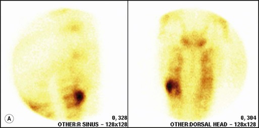
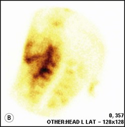
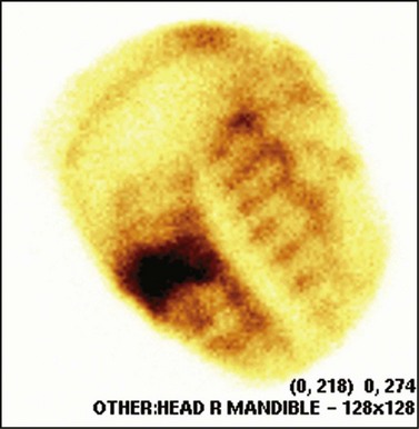
99mTc-MDP uptake associated with periapical infection is typically focal and intense, with IRU located over the apical region of the affected tooth (Fig. 13.48). Region of interest (ROI) studies performed on cases of periapical infection have shown IRU of 24–259 % greater than the same region on the contralateral side when using right and left lateral views.14,25 Because ‘strike through’ (lesions with high uptake may emit gamma rays from the contralateral side of the skull) may occur when comparing two lateral views, ROI taken from left and right sides on a dorsal (or ventral) view can show an even greater IRU % (as high as 700 %14) on the affected side compared with the control side. If periapical infection is accompanied by secondary dental sinusitis, the focal intense uptake over the affected apex is surrounded by a diffuse region of moderately increased activity over the affected sinus(es) (Fig. 13.48B). After dental extraction, areas of IRU can be present for up to 24 months postoperatively (Fig. 13.49), presumably due to continued remodeling of the dental alveolus.14
Differentiation of periapical infection from other skull lesions
Areas of IRU on scintigrams are not specific to any particular disease process; therefore, other disorders that cause remodeling or inflammation of osseous structures around the cheek teeth must be differentiated from cases of periapical infection.
Periodontal disease can cause areas of mild to moderate IRU on scintigraphy of the equine skull.13,14,25 However, because this disorder is often bilateral and multifocal and more commonly affects older horses where the cheek teeth are not clearly delineated, it can be difficult to definitively diagnose this disorder using scintigraphy. Periodontal disease should be clinically evident from a thorough examination of the oral cavity, and therefore there is little additional benefit from the use of scintigraphy in its diagnosis.
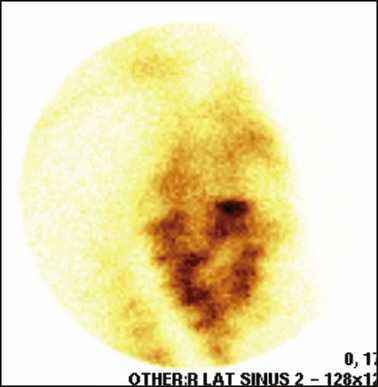
Horses with primary sinusitis may show variable patterns of IRU within the affected paranasal sinuses, but generally IRU is more diffuse and less marked (6–300 %)14,25 than is seen with periapical infection. It should be possible to identify the rostral and caudal maxillary and frontal sinuses individually on scintigrams based on anatomical location with respect to the cheek teeth and ethmoturbinates.
Some cases of equine primary sinusitis exhibit focal area(s) of moderate to marked IRU (26–320 % increase compared with contralateral side;14 Fig. 13.50). This is an important finding, because if these focal areas of IRU that are observed in cases of primary sinusitis happen to be positioned over the apex of a cheek tooth, a false diagnosis of periapical infection may be made. Careful, three-dimensional localization of the focal area of IRU may help prevent such false diagnoses in some cases.
Computed Tomography
Hubert Simhofer, Alexandra Boehler
University for Veterinary Medicine Department IV, Clinical Department for Companion Animals and Horses, Veterinaerplatz 1, A-1210, Vienna, Austria
Introduction
Over the past decade, computed tomography (CT) has been increasingly used in equine examinations and is now available in many referral centers and university hospitals across the globe.28,29 CT is a valuable diagnostic tool30 that provides detailed cross-sectional images of tissues, providing good bone and soft tissue contrast and eliminating the problem of tissue superimposition. CT examination of the equine head region is indicated in cases where clinical and radiographic examinations are inconclusive; when the exact location and extent of a lesion is needed for detailed therapy planning, such as for less invasive surgery or radiation or local chemotherapy,31 and also to accurately monitor cases following treatment.
CT has proven to be very useful in the diagnosis of fractures, dental disease, infection and neoplasia of the equine head. Protocols for the use of CT in evaluating the equine head have been described in detail.28 Despite the fact that CT is increasingly used for the diagnosis of equine dental disease, comparatively little information has been published to date on the appearance of equine dental tissues in health and disease.
Technical principles
CT is a cross-sectional imaging method that uses a rotating X-ray tube and detector system located in a gantry for image acquisition. When the narrow X-ray beam passes through a selected plane of the body, it is partially absorbed when it passes through tissues with different attenuation coefficients (density). Each tissue is assigned a value that represents its attenuation coefficient. Computerized reconstruction programs are used to assign a gray scale value that correlates to the attenuation value of the tissue being imaged.32 Different algorithms can be used for image reconstructions.33 Each CT instrument manufacturer offers algorithms specifically designed for their individual hardware. For equine dental imaging, a soft tissue algorithm is useful for imaging of the soft tissue structures, followed by a reconstruction in a bone algorithm (high resolution) from the raw data, to allow detailed evaluation of dental and bony structures. The acquired sectional images can be reformatted in various two-dimensional planes or three-dimensional models (Fig. 13.51).
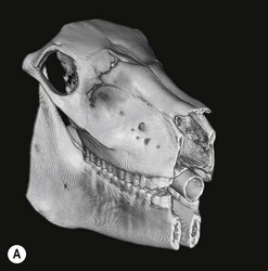
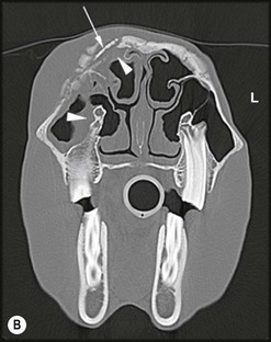
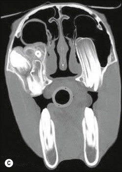
Fig. 13.51 Three-dimensional reconstruction (A) of the bone surface image of an irregular depressed fracture involving the right frontal, nasal, lacrimal, and maxillary bones in a 5-year-old Friesian gelding. The location of fracture lines largely coincides with anatomical suture lines. The distribution and extent of these fractures are well highlighted in the 3D-reformation.
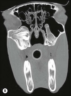
Transverse section CT image (B) at the level of the caudal aspect of the upper 09s (1st molars) of the above horse. Marked subcutaneous soft tissue swelling is present, as is mild swelling of the mucosa of the right dorsal and caudal maxillary sinuses (arrowheads). Fragmentation of the right frontal and nasolacrimal bones is present with palisading new bone formations. A well-defined bone fragment, approximately 3 cm in length, which is hyperdense relative to the adjacent facial bones and separated from them by a 5-mm wide, hypodense rim can be clearly differentiated (arrow). The dorsal facial bones are bilateral irregularly thickened. These CT findings indicate sequestrum formation with surrounding osteomyelitis in an old fracture. The dental structures appear normal in these images.
Evaluation of CT images for the presence or absence of dental disease is usually performed using a bone window.34 By using this particular setting, the dental tissues (cement, enamel and dentin), as well as the lamina dura denta of the alveolus, can be differentiated according to their varying radiodensities.35 However, it is essential to also view the images in an appropriate soft tissue window setting for evaluation of possible changes in adjacent soft tissues. Objectively measuring the density of specific regions of interest (ROI) in Hounsfield Units (HU), allows for improved differentiation of soft tissues.32,36 Care must be taken not to perform measurements in areas that have inherent imaging artefacts, such as streaking artefact28 (Fig. 13.52). In order to improve differentiation of soft tissue masses, post-contrast imaging following use of iodinated contrast agents can be acquired after local application of these agents into fistulous tracts or after intravenous injection.28,37
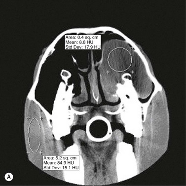
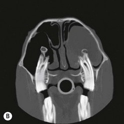
Fig. 13.52 Transverse images at the level of the caudal aspect of the Triadan 10s (2nd molars) of an 8-year-old Hannoverian mare in a soft tissue window (A) and bone window (B). A well-defined soft tissue mass lies within the left ventral conchal and caudal maxillary sinuses surrounded by a thin calcified wall and is causing compression of the dorsal conchal sinus. Density measurements within the mass revealed values of about 10 HU, which is indicative of fluid, whereas measurements of approximately 80 HU were present in the right masseter muscle, which is typical of soft tissue. Bilateral, mild, gaseous inclusions are present within the infundibula of both the maxillary cheek teeth that are imaged, but no significant abnormal dental findings were detected. These CT findings are suspicious of a sinus cyst that was later confirmed during surgery. There is gas present in both infundibula that must be differentiated from pulp disease, which would be much more likely to lead to sinus granuloma formation. Note the streaking artefacts dorsal to the left maxillary tooth within the lesion in the soft window settings (A) that are masked in the wide bone window settings (B). Artefacts compromise Hounsfield measurements.
General anesthesia is usually required for equine CT examinations, but more recently some clinics have acquired facilities to allow CT examination of sedated, standing horses to be performed.38 CT examination of the anesthetized horse requires a custom-built table to allow precise positioning of the patient32,37 (Fig. 13.53). The horse should be positioned as symmetrically as possible32 in either lateral or dorsal recumbency, keeping the head (when in lateral recumbency) or the hard palate (when in dorsal recumbency) parallel to the table. The number, size and angle of slices can be planned after evaluating lateral (Fig. 13.54) and dorsal scout views. The gantry tilt should be minimized to reduce image distortion (especially for image reconstruction purposes). Contiguous, single- or multi-slice helical imaging protocols have been described,35 the latter reducing scan time most. The recommended slice thickness ranges from 4 to 10 mm for evaluating the teeth and sinuses, and from 1 to 2 mm for evaluating special regions of interest (i.e., examining for specific changes in individual teeth or the temporomandibular joint). Two- and three-dimensional image reconstructions may assist in the diagnosis39 and also improve surgical planning. The authors recommend the use of three-dimensional image reconstruction specifically in the evaluation of questionable periodontal or periapical disease.
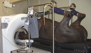
Fig. 13.53 This horse under general anesthesia is positioned in dorsal recumbency on an air filled mattress with its head and legs fixed to the table. The head is positioned as symmetrically as possible.
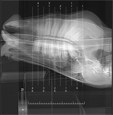
Fig. 13.54 Lateral scout view of a 4-year-old Pinto gelding under general anesthesia. The head is positioned with the hard palate almost parallel to the table so that transverse images are parallel to the long axis of uppermost (mandibular in this position) cheek teeth. The vertical dotted white lines resemble every 5th transverse slice.
Normal appearance of equine dental and periodontal tissues
On transverse CT images of normal teeth (Fig. 13.55A), the peripheral layer of cement is hypodense compared to adjacent enamel. The hyperdense zone of peripheral enamel extends from the erupted (clinical) crown towards the apical region. Dentin is less radiodense than enamel and surrounds the hypodense pulp cavities.35 The pathway of the pulp vasculature through the root canal(s) to the common pulp chamber (only present in recently erupted teeth) and the 5–7 individual pulp canals located in the reserve crown can clearly be followed over their length on 3-D reconstruction images of the cheek teeth. A column of dense secondary dentin lies over each pulp canal at the occlusal surface of normal teeth.
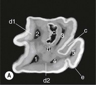
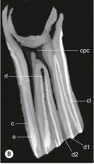
Fig. 13.55
Transverse (A) and sagittal (B) micro CT sections of an extracted Triadan 09 (1st maxillary molar). c, peripheral cement; e, enamel; d1, primary dentin; d2, secondary dentin; rI, rostral infundibulum. Hypodense gas inclusions where there is absence of infundibular cementum are indicative of infundibular cemental hypoplasia, cI, caudal infundibulum; 1–5, pulp cavities; cpc, common pulp chamber.
The rostral and the caudal infundibula are clearly seen in the maxillary cheek teeth, with each infundibulum surrounded by infolded enamel. In some teeth, a central infundibular vascular channel can be detected for the full length of the infundibulum on certain images. Although the central infundibular vascular channel canal is a hypodense structure in sagittal orientation, it must not be misinterpreted as a pulp cavity (Fig. 13.55B). In particular, infundibula may contain gas in cemental defects that must not be mistaken for an infected pulp.
The periodontal ligament appears as a narrow, linear, soft-tissue structure that separates the tooth from the surrounding alveolar bone. In healthy teeth, a thin layer of cortical bone, which is radiographically termed the lamina dura denta or dental lamina, lines the alveolus (Fig. 13.56). Several publications have described the normal CT anatomy of the equine head,28,33,40–43 including normal CT dental anatomy in detail,44,45 and more detailed information about normal CT findings can be found in these papers.
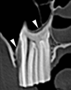
Pathological CT findings in equine dental disease
Signs of apical infection include: hypodense widening of the apical periodontal tissues (Fig. 13.57), sclerosis, and deformation or disintegration of the apical aspect of the lamina dura denta. Concurrent thickening of the overlying periapical soft tissue, sometimes containing gas inclusions, is also usually present. Granuloma formation appears as a soft tissue mass around the apical area of the affected tooth (teeth), which is a feature of chronic dental disease (Fig. 13.58). Infection of the caudal four cheek teeth often leads to secondary sinusitis of the maxillary sinuses34 (Fig. 13.59) when thickened respiratory epithelium, inspissated pus, and/or fluid-lines may be visible in the adjacent sinuses. As CT examinations are usually performed under general anesthesia in dorsal recumbency, purulent fluid originating from an infected cheek tooth may flow from the maxillary sinuses into the ipsilateral frontal sinus (Fig. 13.59).
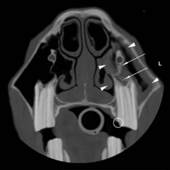
Fig. 13.57 Transverse CT section at the level of mid 209 of a 6-year-old Warmblood gelding that had an intermittent, purulent, left-sided nasal discharge. Moderate thickening is present in the rostral maxillary sinus mucosa and also medial to the infraorbital canal in the ventral conchal sinus (arrowheads). Mild to moderate widening of the periapical periodontal space is present, as is irregular thickening of the dental lamina (arrows) and of the bony plate lying beneath the infraorbital canal. A palatal slab fracture of 209 is present (circle) without any detectable overlying pulpar reaction.
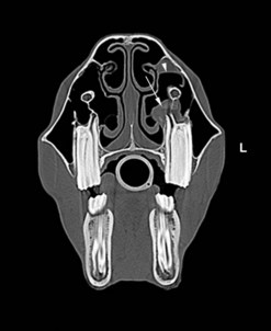
Fig. 13.58 Transverse CT section at the mid-level of the maxillary 09s of a 5-year-old Quarter Horse. A focal soft tissue swelling (granuloma) surrounds the palatal root and hypodense 5th pulp cavity (arrow) of the 209. A fluid-line is present in the ventral conchal sinus (arrowhead) because the image was acquired in dorsal recumbency.
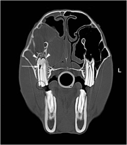
Fig. 13.59 Transverse CT section at the level of the maxillary 110s of an 11-year-old Warmblood. Total opacification and mild expansion of the right caudal maxillary and ventral conchal sinuses are present. There is also some mucosal swelling in the ipsilateral dorsal conchal sinus. The apical dental lamina of 110 is widely separated from the apex and is sclerotic (arrowheads), and there is blunting of both visible roots and irregularity of the dental lamina on the buccal aspect of the affected tooth. A hypodense, bulbous enlargement is present in the proximal aspect of the 2nd pulp canal (arrow). A buccal slab fracture of the crown (circle) has caused changes in at least one (of the two) involved pulp horns.
Changes of the calcified dental tissues occur in long standing cases of apical tooth root infections. Deformation or fragmentation of tooth roots may be visible34 (Fig. 13.59). In some chronic cases, considerable amounts of cement are deposited irregularly around the apex (as described in the gross pathology of these lesions in Chapter 10). Hypodense (black) areas indicating the presence of gas within the pulp or root canals are indicative of pulpitis (Figs 13.58 & 13.59), but many clinically normal equine maxillary cheek teeth have gas within areas of cemental defects in infundibula, that must not be mistaken as evidence of bacterial infection.
Whilst sagittal cheek teeth fractures are usually apparent on thorough clinical examination, they are difficult to diagnose radiographically. However, they are readily detected on CT images (Fig. 13.60) that also allow the configuration and extent of dental fractures to be fully evaluated. Transverse fractures of the teeth are relatively uncommon but may occur secondary to trauma (Fig. 13.61). Lingual or buccal slab idiopathic cheek teeth fractures (Figs 13.62 & 13.63) have been described recently as the most common types of cheek teeth fractures in horses. In such fractured teeth, CT can usually distinguish between single and multiple pulp cavity involvement.46 In some acute cases of dental fractures involving pulp cavities, pulpar changes are not detectable on CT (Fig. 13.62). These fractured teeth may be healing by production of tertiary dentin or, alternatively, might later develop clinical signs of pulpitis and subsequent periapical infection. In the latter type of case, magnetic resonance imaging is useful in the detection of periodontal disease, pulpitis and pulp necrosis.47,48
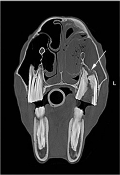
Fig. 13.60 Transverse CT image of a 6-year-old Polo Pony at the mid 209 level. A sagittal midline fracture is present in 209, and the fracture site is packed with heterogeneous food particles. Note the irregularities and disruption of the apical dental lamina (arrow) and marked widening of the periodontal space. The rostral maxillary and ventral conchal sinuses are filled with food with gaseous inclusions. Some thickening of the overlying left nasal bone and mucosal swelling of the dorsal concha are also present.
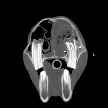
Fig. 13.61 Transverse CT section at the level of the upper 09s in an 18-month-old Welsh Cob with facial swelling of suspected traumatic origin. The CT shows facial asymmetry, left-sided soft tissue (subcutaneous) swelling and thickening and irregularity of the external surface of the maxillary bone dorsal to the facial crest. The left dorsal and ventral conchal, and the rostral maxillary sinuses are completely filled with fluid and gas inclusions and, in turn, these structures are causing total obstruction of the left nasal passages and causing deviation of the nasal septum to the right side. An irregular, radiolucent line running transversely across the apical third of the reserve crown of 209 (arrowheads) and possibly some buccal axial deviation of this tooth are likely due to a traumatic fracture of this tooth. The irregular hypercementosis of the buccal peripheral cemental layer of this tooth and adjacent periodontal reactions are also likely of traumatic origin.
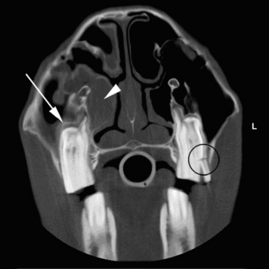
Fig. 13.62 Transverse section at the mid level of the Triadan 10s of an 8-year-old Noriker mare. A buccal slab fracture is present in 210 with exposure of the 1st pulp canal (these fractures also usually involve the 2nd pulp horn) but with no evidence of pulpar, apical, or periodontal changes currently apparent in this tooth. Note the rounded apical area of 110, adjacent periodontal widening (arrow) and complete filling of the right ventral conchal sinus (arrowhead) with fluid, indicative of apical infection of 110 with secondary sinus empyema.
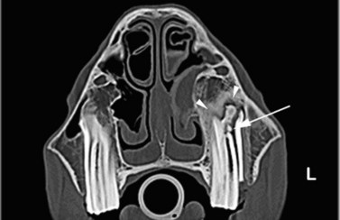
Fig. 13.63 Transverse CT section at the level of the upper 09s of a 4-year-old Thoroughbred mare. The 209 has a buccal slab facture (with loss of fragment) affecting the 1st (or 2nd) pulp horn, which is slightly widened and hypoattenuated. The common pulp chamber of this tooth also contains a rounded, hyperdense structure 4 mm in diameter, most likely a pulp stone (arrow). The roots of this tooth (dental age 3 years) are blunt (rounded) and there is slight widening of the periodontal space apically and bucally. The buccal alveolar bone is heterogeneously thickened, and irregular sclerotic changes are also present in the periapical alveolar bone (arrowheads). The nasal conchae, including the left ventral and dorsal conchal sinuses, are irregularly thickened and distorted, and the adjacent ventral conchal and rostral maxillary sinuses are partially opacified due to the presence of exudate caused by the dental sinusitis.
Infundibular cemental hypoplasia and infundibular caries have been well described in equine teeth. Wide and air-filled irregular cavities can clearly be seen on transverse CT images of some clinically normal sagittally orientated infundibula34 (Fig. 13.64). Although easily diagnosed using CT, infundibular changes are frequently present in horses that are asymptomatic and, in these cases, treatment such as dental extraction is not indicated. A diagnosis of severe infundibular caries penetrating the infundibular enamel is possible using CT examination, and such a finding is of great help when deciding whether to extract or preserve a maxillary cheek tooth. Dorsal plane reformatted images parallel to the occlusal surface show infundibular caries very well.
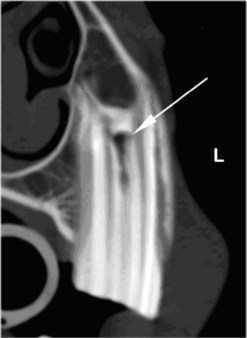
Fig. 13.64 Transverse section CT image at the level of 207 in a 9-year-old Warmblood gelding. Gas is present in the proximal aspect of the imaged infundibulum with irregular thinning of the adjacent infundibular enamel (arrow). Penetration of caries through the infundibular enamel into the surrounding dentin may be present in this tooth.
Considerable efforts have been made recently to improve diagnosis and treatment of periodontal disease. Detailed examination of the periodontal space on CT images can provide considerable information concerning the extent of periodontal disease. A specific equine periodontal disease classification system needs to be established in the near future. Periodontal changes that are detectible on CT range from mild, focal changes, such as widening of the (hypodense) periodontal space, cemental erosions, irregularities in the lamina dura denta (dental lamina), alveolar sclerosis or disruption, and extensive food and gas pocketing with destruction of the supporting maxillary or mandibular bones. The exclusion of periodontal disease is a prerequisite for endodontic therapy.
Dental-associated structures
Sinusitis is a common disease in equids and can be a primary sinusitis (i.e., caused by bacterial infection), or secondary to dental disease, trauma, cystic lesions, mycotic infections or neoplasia.32,34,49 One of the first changes of sinus disease detectable on CT imaging is a focal or diffuse swelling of the sinus mucosa, which must be differentiated from edema of the nasal conchae (turbinates) related to head positioning under general anesthesia.28 A varying degree of intra-sinus fluid accumulation or increased density due to inspissated material and/or mucosal thickening can also be seen. In severe cases of sinusitis, the sinuses are entirely fluid-filled, and the sinus mucosa is indistinguishable from the surrounding fluid. In these cases evacuation of sinus exudate prior to CT examination may facilitate the examination. In long-standing cases, chronic distension of the sinuses with exudate can cause deviation of the nasal septum (Fig. 13.61), distortion of the nasal turbinates (conchae), the facial bones, and even dental apices. Chronic sinusitis may also cause thickening, endosteal sclerosis, and an irregular periosteal reaction of maxillary34 and mandibular bone, and new bone formation may be present along the internal (Fig. 13.65) and external (Fig. 13.66) supporting bony walls of sinuses.
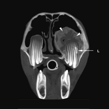
Fig. 13.65 Transverse CT section at the level of the 09s in a yearling. The occlusal surfaces of these unerupted teeth are still covered by soft tissue (dental sac). An expansive lesion above 209 has greatly disrupted the alveolus and adjacent structures. The enamel folds of 109 are irregular at their apical aspects, and the buccal surface of the peripheral enamel has a focal thickening (arrow). The inner borders of the periapical swelling have thick, irregular new bone formation (arrowheads), and the adjacent ventral conchal and rostral maxillary sinuses are completely filled with a hypodense substrate. The outline of the left facial crest is slightly irregular, and overall, the maxillary bone appears heterogeneous. In summary, these CT images indicate a chronic proliferative sinusitis and maxillary bone osteitis secondary to apical infection of the unerupted tooth.
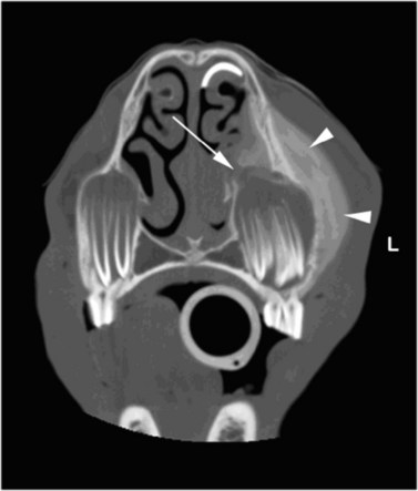
Fig. 13.66 Transverse CT section at the level of the upper 06s of a 2-year-old Quarterhorse. A normal eruption cyst overlies the 106 with the remnant of the underlying deciduous tooth (506) lying beneath it. A much larger, cyst-like swelling lies over the apex of 206 that is distorted and abnormally angled medially, towards the ventral nasal concha (arrow), with disruption of the medial aspect of the alveolus. A marked degree of smooth lamellar new-bone formation (arrowheads) has occurred along the adjacent maxillary bones along with adjacent subcutaneous soft-tissue swelling. These CT findings indicate chronic infection of the erupting 206 with penetration of exudate into the nasal cavity. Note the semicircular white line in the dorsal nasal passage due to injection of iodated contrast agent into the nasolacrimal duct that flowed to this site when the horse was in dorsal recumbency under general anesthesia during CT imaging.
The presence of facial swelling and draining sinus tracts is a common reason for referral of equine patients. Dental disease, dentigerous cysts (heterotopic polyodontia; Fig. 13.67), head trauma, osteomyelitis and, infrequently, neoplasms of the head region are the most common causes of such facial swellings and tracts. In most affected horses, a definite diagnosis can be obtained using clinical and radiographic examinations. However, CT can be helpful in the examination of more difficult cases. Despite the fact that a specific tumor classification is not possible using CT, the extent and the grade of destruction of adjacent hard and soft tissues can be clearly evaluated, which enables a more accurate treatment plan and prognosis to be given (Fig. 13.68).
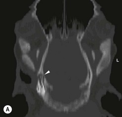
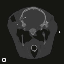
Fig. 13.67 Dorsal (A) and transverse (B) CT sections at the level of the temporal bone of a 6-month-old female Noriker foal. A horizontally orientated, heterotopic cheek tooth (’dentigerous cyst’) lies within the right calvarium. The cerebral bony lamina is markedly thinned to just 1 mm wide (arrowheads) at the rostral aspect of this tooth. Gaseous inclusions and bony fragments lie within the soft tissues lateral and ventral to the dentigerous cyst, which was caused by the previous surgical removal of a second heterotopic tooth.
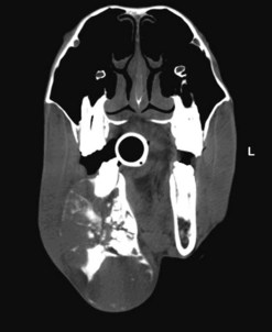
Fig. 13.68 Transverse CT image at the level of the 410 in a 12-year-old, New Forest Pony stallion, using a soft tissue window. Amorphous, hyperdense structures are clearly visible in the grossly enlarged and deformed right hemimandible. Such massive bony destruction caused by an expansile lesion is a feature of an ameloblastoma, which was diagnosed in this case. CT examination was invaluable for the planning of subsequent radiotherapy. The neoplasm did not enlarge for at least two years following this therapy.
In complicated cases of ongoing dental-related disease, CT examination can be very helpful in assessment of treatments and, for example, in planning subsequent treatment strategies for oro-nasal fistulae (Fig. 13.69) or sequestration of alveolar bone or dental remnants, bone necrosis, or ongoing osteomyelitis (Fig. 13.51).
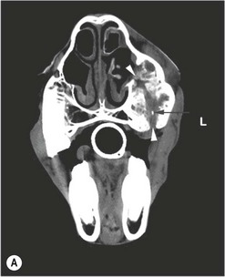
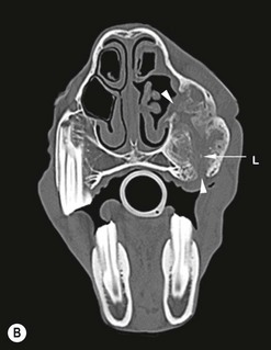
Fig. 13.69 Transverse CT images at the level of the 08s some 6 months following extraction of the 208, as viewed in a soft-tissue (A) and bony window (B). A soft-tissue swelling overlies the left maxillary bone, which has an irregular bulbous expansion and contains irregular, hypersclerotic areas. An oro-nasal fistula (arrowheads) is evident as an irregular lateral expansion of the maxillary bone, and a sclerotic appearance of the medial aspect of the ventral concha. An isolated, small, hyperdense bone sequestrum or dental remnant (arrow) is identified more easily in the soft tissue window (A) as compared to the bony window (B).
Disorders of the temporomandibular joints and hyoid bones can clinically mimic dental disease. The associated bony structures can be assessed accurately in CT. Alterations due to infectious disease and fractures have already been described.50–52 Typical features of infectious temporomandibular joint disease are widening of the joint space, bony defects, and soft tissue swelling (Fig. 13.70), as further described in Chapter 23.
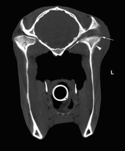
Fig. 13.70 Transverse CT images at the level of the temporomandibular joints (TMJ). Marked soft tissue swelling is present in the left temporal region. The left TMJ joint space is widened, and the joint has irregular bony surfaces. There are discrete, lytic changes in the subchondral bone of the mandibular condyle (arrows) and mild irregular periosteal new bone formation on the dorsolateral aspect of the left hemimandible (arrowhead). The articular disc can be identified as a slightly hyperdense structure lying in the center of the left TMJ.
1 Gibbs C. Dental imaging. In: GJ Baker GJ, Easley J. Equine dentistry. 2nd edn. Edinburgh: Elsevier; 2005:171–202.
2 Baker GJ. Some aspects of equine dental radiology. Equine Vet J. 1971;3:46–51.
3 Lane JG, Gibbs C, Meynick SE, et al. Radiographic examination of the facial, nasal and paranasal sinus regions of the horse: I. Indications and procedures. Equine Vet J. 1987;19:466–473.
4 O’Brien RT. Intra-oral dental radiography: experimental study in two horses and a llama. Veterinary Radiology and Ultrasound. 1996;37:414–416.
5 Easley J. A new look at dental radiology. In: Proceedings of the American Association of Equine Practitioners 2002; 48: 412–420
6 Barakzai SZ, Dixon PM. A study of open-mouthed oblique radiographic projections for evaluating lesions of the erupted (clinical) crown. Equine Veterinary Education. 2003;15:143–148.
7 Klugh DO. Intraoral Radiography of Equine Premolars and Molars. In: Proceedings 49th Annual Convention of the American Association of Equine Practitioners, New Orleans, LA, USA. Ithaca: International Veterinary Information Service www.ivis.org, 2003. Document No. P0640.1103
8 Dixon PM, Copeland AN. The radiological appearance of mandibular cheek teeth in ponies of different ages. Equine Veterinary Education. 1993;5:303–307.
9 Gibbs C, Lane JG. Radiographic investigation of the facial, nasal and paranasal sinus regions of the horse:II. Radiological findings. Equine Vet J. 1987;19:474–492.
10 Townsend NB, Hawkes CS, Rex R, et al. Investigation of the sensitivity and specificity of specific radiological abnormalities for diagnosis of equine cheek tooth periapical infection. In: Proceedings of the ECVS annual symposium, Nantes, France, 2009 pp TO ADD
11 Barakzai SZ, Knowles J, Kane-Smyth J, Townsend N. Trephination of the equine rostral maxillary sinus: efficacy and safety of two trephine sites. Veterinary Surgery. 2008;37:278–282.
12 Tremaine WH, Dixon PM. A long term study of 277 cases of equine sinonasal disease. Part 1: Details of horses, historical, clinical and ancillary diagnostic findings. Equine Vet J. 2001;33:274–282.
13 Weller R, Livesey L, Maierl J, et al. Comparison of radiography and scintigraphy in the diagnosis of dental disorders in the horse. Equine Vet J. 2001;33:49–58.
14 Barakzai SZ. Use of scintigraphy for the diagnosis of suspected equine dental and paranasal sinus disorders. MSc Thesis, University of Edinburgh, 2005
15 Barakzai S, Tremaine WH, Dixon P. Use of scintigraphy for diagnosis of equine paranasal sinus disorders. Veterinary Surgery. 2006;35:94–101.
16 Engels EA, Terrin N, Barza M, Lau J. Meta-analysis of diagnostic tests for acute sinusitis. J Clin Epidemiol. 2000;53:852–862.
17 Berger G, Steinberg DM, Popovtzer A, et al. Endoscopy versus radiography for the diagnosis of acute bacterial rhinosinusitis. European Archives of Otorhinolaryngology. 2005;262:416–422.
18 DeBowes RM, Gaughn EM. Congenital dental disease of horses. Veterinary Clinics of North America: Equine Practice. 1998;14:273–289.
19 Quinn GC, Tremaine WH, Lane JG. Supernumerary cheek teeth (n=24); clinical features, diagnosis, treatment and outcome in 15 horses. Equine Vet J. 2005;37:505–509.
20 Knottenbelt DC, Kelly DF. Oral and dental tumors. In: Baker GJ, Easley J. Equine dentistry. 2nd edn. Edinburgh: Elsevier; 2005:127–148.
21 Pirie RS, Dixon PM. Mandibular tumors in the horse: a review of the literature and seven case reports. Equine Veterinary Education. 1997;5:287–294.
22 Cotchin E. A general survey of tumors of the horse. Equine Vet J. 1977;9:16–21.
23 Lane JG, Longstaffe JA, Gibbs C. Equine paranasal sinus cysts: a report of fifteen cases. Equine Vet J. 1987;19:537–544.
24 Archer DC, Blake CL, Singer ER, et al. The normal scintigraphic appearance of the equine head. Equine Veterinary Education. 2003;15:243–249.
25 Archer DC, Blake CL, Singer ER, et al. Scintigraphic appearance of selected diseases of the equine head. Equine Veterinary Education. 2003;15:305–313.
26 Gayle JM, Redding WR, Vacek JR, et al. Diagnosis and surgical treatment of periapical infection of the third mandibular molar in five horses. Journal of the American Veterinary Medical Association. 1999;215:829–832.
27 Ramzan PHL. The head. In: Dyson SJ, Pilsworth RC, Twardock AR, Martinelli MJ. Equine scintigraphy. Newmarket: Suffolk; 2003:225–226. Equine Veterinary Journal
28 Solano M, Brawer RS. CT of the equine head: technical considerations, anatomical guide, and selected diseases. Clinical techniques in equine practice. 2004;3:374–388.
29 O’Brien RT, Biller DS. Dental imaging. Veterinary Clinics of North America: Equine Practice. Dentistry. 1998;14:259–271.
30 Heufelder B, Mettenleiter E, Tietje S, Traencker D-M. Fallbericht eines komplexen Odontoms beim Pferd – Klinik, Röntgen, Sonographie und Computertomographie. Tierärztliche Praxis. 1994;22:155–158.
31 Annear MJ, Gemensky-Metzler AJ, Elce YA, Stone SG. Exophthalmus secondary to a sinonasal cyst in a horse. Journal of American Veterinary Medical Association. 2008;233:285–288.
32 Tietje S, Becker M, Böckenhoff G. Computed tomographic evaluation of head diseases in the horse: 15 cases. Equine Vet J. 1996;28:98–105.
33 Morrow KL, Park RD, Spurgeon TL, et al. Computed tomographic imaging of the equine head. Veterinary Radiology and Ultrasound. 2000;41:491–497.
34 Henninger W, Frame EM, Willmann M, et al. CT features of alveolitis and sinusitis in horses. Veterinary Radiology and Ultrasound. 2003;44:269–276.
35 Puchalski SM, Computed tomographic and ultrasonographic examination of equine dental structures: normal and abnormal findings. Proceeding American Association of Equine Practitioners, Focus Meeting, Indianapolis, 2006, pp 173–180
36 Tietje S. Zur Bedeutung der Computertromographie beim Pferd, Teil 1: Erkrankungen an Kopf und Hals. Der praktische Tierarzt. 1996;77:1090–1098.
37 Barbee DD, Allen JR, Gavin PR. Computed tomography in horses – technique. Veterinary Radiology. 1987;28:144–151.
38 Nelson A. Computed tomography and joint disease. Proceedings of the 47th BEVA Congress, Handbook of Presentations 2008, p. 267
39 Banner TA. Using computed tomography in evaluation of equine dental disease. Proceeding American Association of Equine Practitioners, Focus Meeting, Indianapolis, 2006, pp 289–292
40 Smallwood JE, Wood BC, Taylor WE, Tate LP, Jr. Anatomic reference for computed tomography of the head of the foal. Veterinary Radiology and Ultrasound. 2002;43:99–117.
41 Probst A, Henninger W, Willmann M. Communications of normal nasal and paranasal cavities in computed tomography of horses. Veterinary Radiology and Ultrasound. 2005;46:44–48.
42 Nöller C, Nowak M, Jamann J, et al. Klinische Anatomie der Nasen- und Nasennebenhöhlen des Pferdes – Grundlagen für die Endoskopie, Computertomographie und Chirurgie. Tierärztliche Praxis. 2007;23:47–58.
43 Rodríguez MJ, Latorre R, López-Albors O, et al. Computed tomographic anatomy of the temporomandibular joint in the young horse. Equine Vet J. 2008;40:566–571.
44 Windley Z, Weller R, Tremaine WH, Perkins JD. Two and three-dimensional computer tomographic anatomy of the enamel, infundibula and pulp of 126 equine cheek teeth. Part 1: Findings in normal teeth. Equine Vet J 2009; 41: 433–440
45 Windley Z, Weller R, Tremaine WH, Perkins JD. Two and three-dimensional computer tomographic anatomy of the enamel, infundibula and pulp of 126 equine cheek teeth. Part 2: Findings in abnormal teeth. Equine Vet J 2009; 41: 441–447
46 Bienert A, Bartmann CP. Kronenteilfrakturen im Bereich der Backenzähne des Pferdes. Tierärztliche Praxis. 2008;36(G):266–272.
47 Gerlach K, Gerhards H. Erkrankungen von Pferdezähnen in der magnetresonanztomographischen Diagnostik. Vet-Med Report, Sonderausgabe V1/32. 20.Arbeitstagung der DVG-Fachgruppe Pferdekrankheiten, 2
48 Gerlach K, Gerhards H. Magnetresonanztomographische Merkmale von Zubildungen im Bereich der Nase, Nasennebenhöhlen und der angrenzenden Knochen: retrospektive Analyse von 33 Pferden. Pferdeheilkunde. 2008;24:565–576.
49 Feige K, Geissbühler U, Fürst A, et al. Sinusitis beim Pferd: Eine retrospektive Untersuchung anhand von 55 Fällen. Pferdeheilkunde. 2000;16:495–501.
50 Warmerdam EPL, Klein WR, van Herpen BPJM. Infectious temporomandibular joint disease in the horse: computed tomographic diagnosis and treatment of two cases. Veterinary Record. 1997;141:172–174.
51 Chalmers HJ, Cheetham J, Dykes NL, Ducharme NG. Computed tomographic diagnosis – stylohyoid fracture with pharyngeal abscess in a horse without temporohyoid disease. Veterinary Radiology and Ultrasound. 2006;47:165–167.
52 Nagy AD, Simhofer H. Mandibular condylectomy and meniscectomy for the treatment of septic temporomandibular joint arthritis in a horse. Veterinary Surgery. 2006;35:663–668.