Chapter 7 Electricity (DC)
Chapter contents
7.1 Aim
The aim of this chapter is to introduce the reader to the concept of electron flow as a means of conducting electricity. Factors affecting the resistance to this flow will be explored and Ohm’s law will be discussed. The consequences of resistance in terms of electrical ‘power loss’ will be discussed and the practical implications of this in the design of X-ray-generating apparatus will be considered.
7.2 Introduction
In Chapter 6 we considered the behaviour of static electrical charges. This chapter considers the behaviour of electrical charges which are unidirectional in their movement – direct current or DC electricity. Batteries produce a DC current and it is also found in the form of a rectified supply (see Ch. 28). In a vacuum, liquid or gas (e.g. in an air ionization chamber; see Ch. 27), both positive and negative charges move with relative freedom. These charges are called ions. In a solid, however, the atomic nuclei are relatively tightly bound to other atoms and so take no part in the flow of charge. The electrical properties of a given solid are determined by the way in which the orbiting electrons behave.
7.3 Simple electron theory of conduction
To explain why some materials readily allow a flow of electrons (i.e. are good electrical conductors) and other materials will only allow electron flow in extreme conditions (i.e. are good insulators), we need to look more closely at the structure of the atom. This chapter will only look at atomic structure in terms of explaining the electrical properties of the material and there will be a fuller description of the atom in Chapter 18.
The nucleus of the atom contains protons (+ve charge) and around this in orbitals are electrons (−ve charge). We can appreciate that electrons near the nucleus experience a high level of attraction (unlike charges attract) and are thus said to be tightly bound. Electrons in the more remote orbitals experience less force of attraction from the nucleus (remember F ∝ 1/d2) and are also repelled by other electrons which lie between them and the nucleus and so are said to be more loosely bound. Because the electrons in a given single atom are influenced by only that atom, the electrons lie at discrete energy levels, as shown in Figure 7.1A.
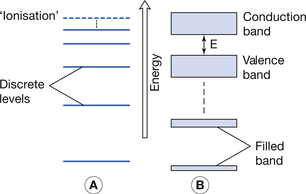
Figure 7.1 (A) Electron energy levels in a solitary atom. (B) Electron energy bands in an atom of a solid.
When electrons are brought closer together, as in a solid, the orbitals of the electrons are strongly influenced by the proximity of neighbouring atoms. This means that electrons are no longer at discrete energy levels but that they are now within a band of energies. This situation is shown in Figure 7.1B.
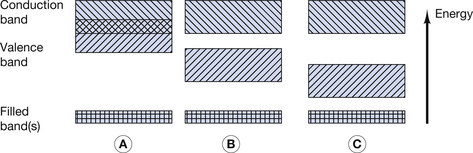
For the purpose of this discussion, only the outer two energy bands are of interest to us: the valence band and the conduction band. The valence band is that band which contains the outermost electrons of the atom and may be partially or completely full of its permitted maximum number of electrons. The configuration of electrons in the valence band determines the chemical properties of the atom, i.e. its ability to form chemical bonds with other atoms. If electrons exist further away from the nucleus than the valence band, then their energies lie in the conduction band. This band is populated with electrons that have, for some reason, become free from their original atoms. Because of this, once an electron is in the conduction band of a solid, it is able to move relatively freely and may take part in electrical conduction through the material. A material with a large number of electrons in the conduction band is a good electrical conductor whereas a material with no electrons in the conduction band is a perfect electrical insulator. Whether or not a material is a conductor, an insulator or a semiconductor is determined by the number of electrons in the conduction band. This number is in turn determined by the size of the forbidden energy gap (E) which exists between the top energy of the valence band and the bottom energy of the conduction band. The arrangement of the valence and conduction bands for conductors, semiconductors and insulators is shown in Figure 7.2. Each of the above will now be considered individually.
7.3.1 Electron arrangements in a conductor
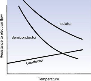
As can be seen from Figure 7.2A, the conduction band and the valence band of energies overlap in a conductor. As a result, a large number of electrons always exist in the conduction band and because of this there is a ready exchange of electrons between the valence and conduction bands. This means that these electrons can be moved through the solid with little resistance to their flow. The main opposition to their flow arises from collisions with other electrons or atoms. If the temperature of the conductor is increased, there is an increase in the vibration of the atoms and a corresponding increase in the likelihood of collision with moving electrons. From this we can see that the opposition (or resistance) to the flow of electrons in a conductor will increase with an increase in its temperature.
As mentioned in Section 7.3.1, the main cause of resistance to the flow of electrons in a conductor is collisions with other atoms. It would seem logical to suggest that if the vibration of the atoms could be reduced, or even stopped, then the resistance of the conductor could be reduced. This is done by cooling the conductor to temperatures close to absolute zero. At these temperatures, atomic vibration ceases to exist and so flow of electrons through the conduction band is virtually unimpeded. Materials operating in this mode are known as superconductors and this technique is used to produce the large magnetic field required for magnetic resonance imaging (MRI).
7.3.2 Electron arrangements in a semiconductor
In a semiconductor, there is a gap between the maximum energy of the valence band and the minimum energy of the conduction band (Fig. 7.2B) and so electrons need to be given energy to bridge this gap and flow through the material (this will be discussed in more detail in Ch. 15, which deals with semiconductors). Thus, semiconductors have a greater resistance to the flow of electrons than conductors. If we increase the temperature of the semiconductor, we will increase the energy of the electrons in the valence band and so make it easier for them to transfer to the conduction band and move through the solid. Thus, increasing the temperature of a semiconductor will reduce its resistance to the flow of electrons.
7.3.3 Electron arrangements in an insulator
In an insulator, there is a significant gap between the maximum energy of the valence band and the minimum energy of the conduction band (Fig. 7.2C). This means that electrons cannot readily bridge this energy gap, and so the conduction band contains no electrons, making conduction impossible. If the material is heated, then the electrons in the valence band gain energy, and so the gap between the valence and the conduction bands is narrowed, making it more likely that electrons can jump the gap. Thus, increasing the temperature of an insulator reduces its resistance.
The effect on the resistance to the flow of electrons of increasing the temperature is shown in Figure 7.3.
7.4 Electric current
Electricity is the flow of electrons in a material. The rate of flow of electrons is a measure of the electric current. In order to produce a current, the following conditions must be satisfied:
• There must be a source of electric potential difference (see Sect. 6.8.2).
• There must be a complete circuit around which the electrons are able to travel.
These two points are illustrated in Figure 7.4. The battery (B) is a source of potential difference, but if the switch (S) is open (as in Fig. 7.4A), no electric current flows and the bulb does not light up. When the switch is closed (Fig. 7.4B), a complete circuit exists around which electrons are able to flow and so the bulb lights up. The potential difference may be thought of as the driving force that causes electrons to flow, while the current is the rate of flow of electrons, i.e. the number of electrons passing a given point in unit time.
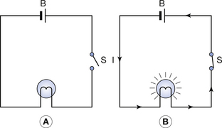
Figure 7.4 (A) The switch (S) is open and so no current flows through the circuit. (B) When the switch is closed, current will flow through the circuit and the bulb will light. This shows that a continuous circuit is necessary for electrical current to flow.
An electric current of 1 ampere (A) flows at a point if a charge of 1 coulomb (C) flows past that point per second.
Thus, we can say mathematically:

From Section 6.4, we know that a charge of 1 coulomb is equivalent to approximately 6 × 10¹⁸ electrons so 1 ampere is simply this number of electrons passing a point in 1 second.
We are accustomed to an instant response when we close an electrical switch and so it is surprising to discover that the average velocity of electrons in a circuit is only in the order of 0.5 mm.s−1. When the switch is closed, electrons start to flow through the whole circuit and so the bulb in Figure 7.4 will light up even if the electrons from the battery have not yet reached it – this is similar to the situation where water enters a pipe from a reservoir when a tap is opened; water leaves the tap immediately, although it might be some time before the water from the reservoir reaches it.
7.5 mA, mAs and millicoulombs
The electric current through an X-ray tube is a small one and so it is measured in milliamperes (mA) rather than in amps: 1 mA=10−3 A. This measures the rate of flow of electrons through the X-ray tube. If we wish to measure the number of electrons that have travelled across the tube during a given radiographic exposure, then we need to multiply the rate of flow by the time of the exposure. This unit is in milliampere-seconds (mAs) where:

Now the total number of electrons, which have crossed the X-ray tube, is just a measure of the charge, measured in coulombs. From Equation 7.1:

By cross-multiplying (see Appendix A):


7.6 Potential difference and electromotive force
We have already considered potential difference in Section 6.8.2 and defined the potential difference in volts:
The potential difference in volts is the work done in moving 1 coulomb of positive charge from one point to another.

In electricity, we are concerned with moving charges and, as mentioned previously, we can regard the potential difference as the ‘driving force’, which moves the electron along a conductor.
Electromotive force (EMF) is also expressed in volts and is a measure of electrical potential energy developed across a source of electricity (e.g. a battery or a generator). The EMF is the ‘driving force’ behind the electron flow in the circuit.
It is therefore possible to speak about the potential difference (PD) across any part of the circuit including the source of electricity, whereas the term EMF is reserved solely for the latter. It would not be correct to use the term ‘EMF across a resistor’ as a resistor is not a source of electricity – the appropriate terminology would be ‘the PD across a resistor’.
It is interesting to note that the PD across the terminals of a battery is less than the EMF when a current flows. This is due to the internal resistance of the battery. The effect is known as regulation. Similar effects are observed with transformers and will be discussed more fully in Chapter 14.
7.7 Resistance
The elementary theory of conduction discussed earlier in this chapter refers to two mechanisms that impede electron flow:
1. Lack of ‘free’ electrons in the conduction band – as in an insulator.
2. Collisions between flowing electrons with other vibrating electrons in the material.
This impedance to the flow of electrons is given the term electrical resistance or simply resistance and is measured in ohms. Obviously, from the earlier discussion, insulators have much higher resistance than conductors of the same shape and size. The resistance of a conductor can vary depending on a number of factors, which will be discussed below.
7.7.1 Factors affecting resistance
The resistance of a substance will be affected by:
Note that the resistance of the substance is not affected by either the potential difference across it or by the current flowing through it.
7.7.1.1 Shape
The shape of a body is capable of infinite variation, so for simplicity we shall consider circular conductors of constant cross-sectional area.
Figure 7.5 illustrates such a body and the effect on the resistance R of altering its length l and its cross-sectional area A.
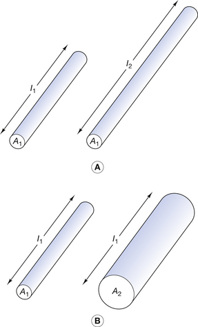
Figure 7.5 Factors affecting resistance of a conductor. In (A) the conductors are of different lengths and the resistance increases with the length. In (B) the conductors have differing cross-sectional areas and the resistance is inversely proportional to the cross-sectional area.
The resistance is proportional to the length of the conductor (R ∝ l). If we consider a situation where the length of the conductor is doubled, then electrons travelling along the conductor have twice as many vibrating atoms to get past, so the resistance to their flow will be doubled.
The resistance is inversely proportional to the cross-sectional area (R ∝ l/A). If the area is doubled, there are twice as many electrons capable of conducting charge. The number of atoms each electron must get past for the length of the conductor remains the same and so doubling the area will halve the resistance.
7.7.1.2 Type of substance
By definition, good electrical conductors will have a lower resistance than insulators. Different metals also have different values of resistance. As we have just seen, the shape of the substance also affects its resistance, so that a standard shape and size must be used when comparing the resistance of different materials. The standard used is a cube of side 1 metre and the resistance is measured when a current is passed between opposing faces of the cube. The value of the resistance so obtained is called the resistivity or the specific resistance of the material and is measured in ohm-metres. Resistivity is given the symbol ρ (Greek rho) and it is clear that the resistance of the material will be directly proportional to its resistivity: R ∝ ρ.
If we now consider all the factors discussed above, we have:

In the International System of Units (SI) system, ρ is defined so that the constant of proportionality in the above equation is unity and we can say:

The resistivity of insulators is about 1 million times greater than those of semiconductors, which in turn are about 1 million times greater than those of metallic conductors.
7.7.1.3 Temperature
As described at the beginning of this chapter, a change in temperature affects the resistance of a body. This effect is different for conductors, semiconductors and insulators, as shown in Figure 7.3. Because of these variations, resistance is usually quoted at a particular temperature (e.g. 20°C). The temperature coefficient of resistance, α, is defined as the fractional change in resistance (or resistivity) per unit temperature change:
7.8 Ohm’s Law
Ohm’s law applies to metallic conductors and combines, in a simple way, the relationship between current, potential difference and resistance. It is found experimentally that the current flowing through a conductor is proportional to the potential difference applied across it – as the driving force on the electrons is increased, so the number of electrons passing a point in unit time increases by a proportional amount. If a potential difference of 2 volts causes a current of 1 amp to flow through a conductor, then a potential difference of 4 volts will cause a current of 2 amps to flow. Ohm’s law may be formally stated as follows:
The current flowing through a metallic conductor is proportional to the potential difference which exists across it provided that all physical conditions remain constant.
The main physical condition, which must remain constant, is the temperature of the conductor, as an alteration in the temperature will cause an alteration in the resistance (see Sect. 7.7.1).
Ohm’s law may be stated mathematically thus:

where I and V are the magnitude of the current and the potential difference respectively.
Note that Ohm’s law does not mention the word resistance. The resistance of the body (R) is introduced into Equation 7.8 as a constant of proportionality (see Appendix A) and so the equation may now be rewritten:

As we have already established, R is a constant for a given conductor at a given temperature and does not depend on V or I.
R is measured in ohm (Ω) and we can see from Equation 7.9 that when V = 1 volt and I = 1 amp, then R will be 1 ohm. The ohm may be defined as follows:
A body is said to have an electrical resistance of 1 ohm if a potential difference of 1 volt across it produces an electrical current through it of 1 ampere.
(Note that a potential difference always occurs across a body, never through it. Likewise, an electrical current always flows through a body and does not exist across it.)
Although Ohm’s law is simple in its formulation, it has far-reaching implications which can be applied to radiological physics. The most important of these will now be discussed.
7.8.1 Resistors in series
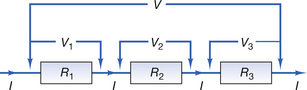
If we join resistors in series (end-to-end) and apply a potential difference of V volts across the unit, then a current of I amp flows through it. This is shown in Figure 7.6. Note that the same current flows through each resistor since the whole unit may be regarded as a continuous circuit and so electrons are neither lost nor gained throughout the circuit. Also note that the potential difference across the ends of the unit is simply the sum of the potential differences across each resistor (V=V1+ V2+V3). We wish to calculate the effective resistance of the unit (R), i.e. what would be the value of a single resistor which would behave in exactly the same way as the whole unit?
If we apply Ohm’s law to each resistor in turn then we get:
If we apply Ohm’s law to the total unit then:

By substituting this value of V/I into Equation 7.10A, we get:

Thus, when resistors are connected in series, the total resistance may be obtained simply by adding together the values of each separate resistor.
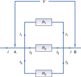
7.8.2 Resistors in parallel
A potential difference of V exists across points A and B in Figure 7.7 and, since each resistor is connected to A and B, the potential difference across each resistor is also V volts. Electrons flow into the circuit at point A and then some will pass through each resistor to meet again at point B. Since electrons are neither gained nor lost in the circuit:

If we apply Ohm’s law to each of the resistors, we get:
By substituting these values in Equation 7.11A:
If we apply Ohm’s law to the whole unit (assuming it has a resistance R), then we get:


If we now substitute this value in Equation 7.11B, we get:
7.9 Electrical energy and power
To get an electric current to flow through a conductor, the electrons must be driven by a potential difference. As the electrons move through the conductor they are involved in collisions with the atoms of the conductor and so work must be done to keep all the electrons moving in the same direction. The electrons dissipate energy to the atoms of the material, which they pass through, and so heat is produced in the material – this is the mechanism by which the filament of the X-ray tube is heated to produce electrons by thermionic emission (see Chapter 30).
7.9.1 The joule
As already discussed (Sect. 4.3), the joule is the SI unit of energy. The key to the method of calculating electrical energy lies in the definition of potential difference. As we discovered in Section 6.8.3, the potential difference between two points is 1 volt when 1 joule of work is done in moving 1 coulomb of positive charge from one point to the other. Thus, we can say:

or:

Since the ampere is a rate of flow of charge of 1 coulomb per second, then we can say:

7.9.2 The watt
We also saw in Section 4.3 that the SI unit of power is the watt, where 1 watt=1 joule per second. Thus, we can say that:
or:

This is a general equation used in the calculation of electrical power, which applies to any electrical system. It is, however, particularly useful to apply this formula to a metallic conductor which obeys Ohm’s law.
7.9.3 Power in a resistor
Consider a current I passing through a metallic resistor of resistance R when a potential difference V is applied across its ends. As previously discussed:

However, we can apply Ohm’s law to the resistor:


By similar manipulations of Ohm’s law, we can get two possible equations for the electrical power in a resistor:

The second equation is probably the most useful one in radiography.
7.10 Power loss in cables
If we consider electricity in the form of a current I passing through a cable with a resistance R, it becomes apparent that some of the available electrical power will be ‘lost’ in the cable. The term ‘lost’ does not imply that there is a breach of the law of conservation of energy but that the power is not available for the user at the far end of the cable – the ’lost’ energy is in fact converted into heat.
It is obviously desirable that the power which is lost in the cables be kept to a minimum as this is not available to the user. If we consider that the power loss is given by the equation P=I2R, then it can be seen that the power loss can be kept to a minimum in one of two ways:
7.10.1 Reducing the current flowing within the cable
Electrical power (P) is a combination of the potential difference (V) across the cables and the current (I) flowing through them, i.e. P=VI. If we wish to transmit a given amount of electrical power with the minimum loss in the cables, this can be done by using a high voltage and a low current. This is shown in Figure 7.8 where a power of approximately 100 watts is required to heat the filament of the X-ray tube. This power is transmitted from the voltage selector to the filament transformer (see Ch. 14) in the form of a relatively high voltage and low current. At the filament we wish to use this power to generate heat, so it is converted to a relatively low voltage and high current at the filament transformer. Similar techniques are used in transmitting power from the generating stations to our homes.
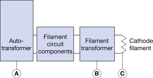
Figure 7.8 Transmission of electrical power from the voltage selector to the X-ray tube filament. Between points A and B power is in the optimum form for transmission with minimum power loss – high voltage and low current. Thus 100 watts of power would be transmitted in the form of 100 volts and 1 ampere. Between points B and C power is in the optimum form for heat generation at the filament. Thus 100 watts of power would be transmitted in the form of 10 volts and 10 amperes.
7.10.2 Reducing the resistance of the cables
This is achieved in two ways: making the cables of a material with a low resistivity (usually copper) and making the cables as thick (large cross-sectional area) as possible. Because the cables are required to transmit power from one point to another, there is little scope for the third possibility – reducing the length of the cables.
7.10.3 Mains cable resistance and X-ray exposures
As we have previously discussed, there is a potential difference across any resistor which is related to the current through the resistor (V=IR). This volt drop is removed from the EMF available when a current flows to an X-ray unit. This can be seen in Equation 7.17:

where Rc is the resistance of the mains cables and V is the PD available at the mains supply when the unit is ‘on load’. It is also worth noting that this volt drop is related to the resistance of the cables and the current to the X-ray unit.
In practice, with static X-ray units, the resistance of the mains cables is fairly constant so it is possible to compensate for this volt drop using a static mains resistance compensator. For mains-dependent mobile units the volt drop can vary for different parts of the hospital – obviously, the mains cables that reach the tenth floor are longer than the cables to the ground floor. This means that this type of mobile unit has an adjustable mains resistance compensator. Usually, the plug for the unit in the ward is coded in some way so that we know the correct setting for the compensator.
Many modern mobile X-ray units overcome this problem by being ‘mains independent’. Such units remove power from the mains in small amounts between exposures (they require to be plugged into the mains when not in use) and then release this power through the X-ray tube during the exposure. The electrical power may be stored in special batteries or in capacitors (see Chapter 13).
In this chapter you should have learnt the following:
• Simple electron theory of conduction (see Sect. 7.3).
• The requirements for a flow of electric current (see Sect. 7.4).
• The relationships between mA, mAs and millicoulombs (see Sect. 7.5).
• The meaning of potential difference and EMF (see Sect. 7.6).
• The meaning of electrical resistance (see Sect. 7.7).
• The factors affecting electrical resistance (see Sect. 7.7.1).
• Ohm’s law (see Sect. 7.8).
• The effect of connecting resistors in series (see Sect. 7.8.1).
• The effect of connecting resistors in parallel (see Sect. 7.8.2).
• The meaning of electrical energy and power (see Sect. 7.9).
• The meaning of the joule (see Sect. 7.9.1).
• The meaning of the watt (see Sect. 7.9.2).
• Power in a resistor (see Sect. 7.9.3).
• Power loss in cables (see Sect. 7.10.1 and Sect 7.10.2).
• Mains cable resistance and X-ray exposures (see Sect. 7.10.3).