Nature of Metals and Alloys
Metals and alloys are used in almost all aspects of dental practice, including the dental laboratory, direct and indirect dental restorations, and instruments used to prepare teeth. Metals and alloys have optical, physical, chemical, thermal, and electrical properties that are exploited to advantage in dentistry and are unique among the basic types of materials (metals, polymers, and ceramics). Although popular press dental journals have occasionally promoted “metal-free” dentistry as desirable, the metals remain the only clinically proven materials for many long-term dental applications. This chapter will summarize the aspects of metals and alloys that are relevant to dentistry. The concepts of crystallization, phase diagrams, alloy microstructure, and alloy strengthening will be described and related to the clinical practice of dentistry. Finally, this chapter will present a foundation for understanding the major classes of alloys used in dentistry: amalgam (see Chapter 11); noble alloys and solders (see Chapter 15); base metal alloys (see Chapter 16), ceramic-metal restorations (see Chapter 19), and implants (see Chapter 22).
CHEMICAL AND ATOMIC STRUCTURE OF METALS
A metal is any element that ionizes positively in solution; metals constitute nearly two thirds of the periodic table (Fig. 6-1). During ionization, metals release electrons. This ability to exist as free, positively charged, stable ions is a key factor in the behavior of metals and is responsible for many metallic properties that are important in dentistry. Another important group of elements shown in Fig. 6-1 are the metalloids, including carbon, silicon, and boron. Although metalloids do not always form free positive ions, their conductive and electronic properties make them important components of many dental alloys.
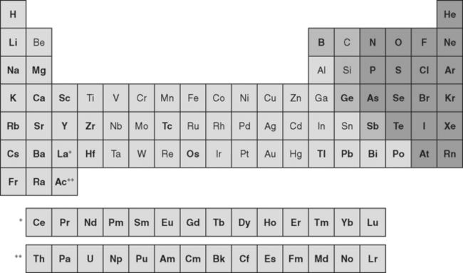
FIGURE 6-1 The periodic table of the elements can be subdivided into metals (lightly shaded backgrounds), metalloids (intermediately shaded backgrounds), and nonmetals (darkly shaded backgrounds). Elements in outline type are used in dental alloys or as pure metals. The metals are elements that ionize positively in solution and comprise the majority of elements in the periodic table. Note that not all elements are shown. The single asterisk indicates the insertion point in the table for the lanthanide series of elements, whereas the double asterisk indicates the insertion point for the actinide series of elements.
ATOMIC STRUCTURE
At the atomic level, pure metals exist as crystalline arrays (Fig. 6-2) that extend for many repetitions in three dimensions. In these arrays, the nuclei and core electrons occupy the atomic centers, whereas the ionizable electrons float freely among the atomic positions. The mobility of the valence electrons is responsible for many properties of metals, such as electrical conductivity. It is important to note that the positively charged atomic centers are held together by the electrons and their positive charge is simultaneously neutralized by the negative electrons; thus, pure metals have no net charge.
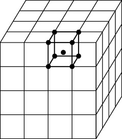
FIGURE 6-2 A typical metallic crystal lattice, in this case a body-centered cubic lattice. Every lattice has a unit cell (shown in bold) that extends (repeats) in three dimensions for large distances. Electrons are only relatively loosely bound to atomic nuclei and core electrons. The nuclei occupy specific sites (shown as dots in the unit cell) in the lattice, whereas the electrons are relatively free to move about the lattice. In reality, the metal atoms are large enough to touch each other.
The relationships between the atomic centers in a metallic crystalline array are not always uniform in all directions. The distances in the x, y (horizontal), and z (vertical) axes may be the same or different, and the angles between these axes may or may not be 90 degrees. In all, six crystal systems occur (Fig. 6-3), and they can be further divided into 14 crystalline arrays. Metallic nuclei may occur at the center of faces or vertices of the crystal. Within each array, the smallest repeating unit that captures all the relationships among atomic centers is called a unit cell (see Fig. 6-2). The unit cells for the most common arrays in dental metals are shown in Fig. 6-4. In the body-centered cubic (BCC) array, all angles are 90 degrees and all atoms are equidistant from one another in the horizontal and vertical directions. Metallic atoms are located at the corners of the unit cell, and one atom is at the center of the unit cell (hence the name body-centered cubic). This is the crystal structure of iron and is common for many iron alloys. The face-centered cubic (FCC) array has 90-degree angles and atomic centers that are equidistant horizontally and vertically (as does the BCC), but atoms are located in the centers of the faces with no atom in the center of the unit cell (hence the name face-centered cubic). Most pure metals and alloys of gold, palladium, cobalt, and nickel have the FCC array. The more complex hexagonal close-pack array occurs with titanium. In this array, the atoms are equidistant from each other in the horizontal plane, but not in the vertical direction.
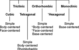
FIGURE 6-3 All metals occur in one of the lattice structures shown. There are six families of lattices, four of which can be subdivided. Each family is defined by the distances between vertices and the angles at the vertices. The body-centered cubic, face-centered cubic, and hexagonal lattices (asterisks) are the most common in dental alloys and pure metals.
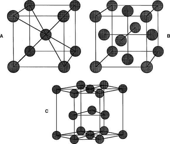
FIGURE 6-4 The three most common crystal lattice unit cells in dental metals and alloys: A, body-centered cubic cell; B, face-centered cubic cell; and C, hexagonal close-packed cell. The atoms (circles) in all three cases would be larger and touching each other. They were drawn smaller to make the structures easier to visualize.
In a metallic crystal, the atomic centers are positively charged because the valence electrons have been released to float about the crystal. At first glance, it seems unlikely that these positively charged atoms could exist so close together. Rather, repulsion between these centers would seem more likely. The metallic bond is a fundamentally important type of primary bond that holds the atomic centers together in a metal lattice. The freely floating electrons bind the atomic centers together and, although it is not directed between specific centers, this metallic bond has a formidable force between atomic centers. The metallic bond is fundamentally different from other primary bonds, such as covalent bonds, which occur in organic compounds, and ionic bonds, which occur in ceramics.
PHYSICAL PROPERTIES OF METALS
All properties of metals result from the metallic crystal structure and metallic bonds described previously. In general, metals have higher densities resulting from the efficient packing of atomic centers in the crystal lattice. The good electrical and thermal conductivity of metals occurs because of the mobility of the valence electrons in the crystal lattice. The opacity and reflective nature of metals result from the ability of the valence electrons to absorb and re-emit light. The melting point occurs as the metallic bond energy is overcome by the applied heat. Interestingly, the number of valence electrons per atomic center influences the melting point somewhat. As the number of valence electrons increases, the metallic bond develops some covalent character that contributes to higher melting points. This phenomenon occurs for iron (Fe3+) and nickel (Ni2+).
The corrosion properties of metals depend on the ability of atomic centers and electrons to be released in exchange for energy. The amount of energy required depends on the strength of the metallic force (related to the freedom of the valence electrons) and the energy that the released ion can gain by solvating in solution. For metals such as sodium and potassium, the metallic bond is weaker because the valence electrons are loosely held, and the energy of solvation is high. Thus, these metals corrode into water with explosive energy release. For metals such as gold and platinum the metallic bond is stronger, valence electrons are more tightly held, and solvation energies are relatively low. Thus, gold and platinum are far less likely to corrode. The corrosion of metals always involves oxidation and reduction. The released ion is oxidized because the electrons are given up, and the electrons (which cannot exist alone) are gained by some molecules in the solution (which is therefore reduced). Further explanation can be obtained in numerous chemistry texts.
Because the distances between metal atoms in a crystal lattice may be different in the horizontal and vertical directions (see Fig. 6-4), properties such as conductivity of electricity and heat, magnetism, and strength may also vary by direction if a single crystal is observed. These directional properties of metals and metalloids have been exploited in the semiconductor industry to manufacture of microchips for computers. However, in dentistry, a single crystal is rarely observed. Rather, a collection of randomly oriented crystals, each called a grain, generally make up a dental alloy. In this case, the directional properties are averaged out across the material. In general, a fine-grained structure (see discussion of grains later in this chapter) is desirable to encourage alloys with uniform properties in any direction. Nonuniformity of directional properties is termed anisotropy.
Like the physical properties, the mechanical properties of metals are also a result of the metallic crystal structure and metallic bonds. Metals generally have good ductility (ability to be drawn into a wire) and malleability (ability to be pounded into a thin sheet) relative to polymers and ceramics. To a large extent, these properties result from the ability of the atomic centers to slide against each other into new positions within the same crystal lattice. Because the metallic bonds are essentially nondirectional, such sliding is possible.
If the metallic crystals were perfect, calculations have shown that the force required to slide the atoms in the lattice would be hundreds of times greater than experience shows is necessary. Less force is necessary because the crystals are not perfect, but have flaws called dislocations. Dislocations allow the atomic centers to slide past each other one plane at a time (Fig. 6-5). Because movement can occur one plane at a time, the force required is much less than if the forces of all the planes have to be overcome simultaneously. An analogy is moving a large heavy rug by forming a small fold or kink in the rug and pushing the fold from one end of the rug to the other. Dislocations are of several types, but all serve to allow the relatively easy deformation of metals. All methods for increasing the strength of metals act by impeding the movement of dislocations. These methods will be discussed later in the chapter.
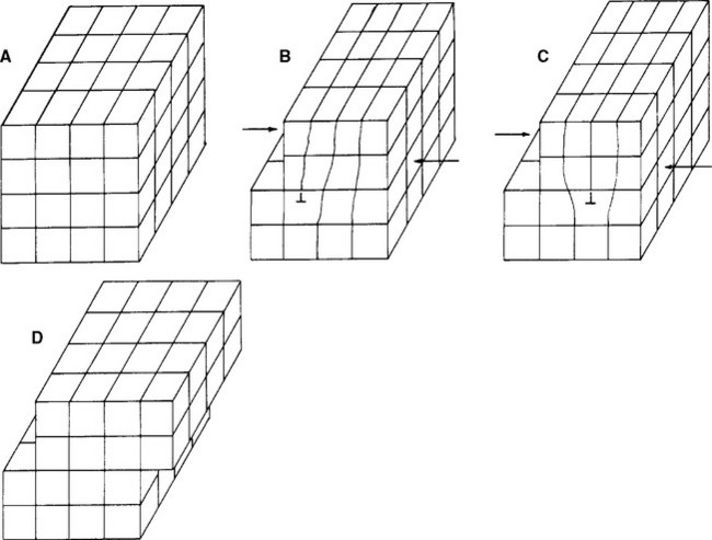
FIGURE 6-5 Sketches representing a crystal and slip mechanisms resulting from movement of a dislocation. By the dislocation moving through the metal one plane at a time (A to B to C to D), far less energy is necessary to deform the metal. Furthermore, the movement occurs without fracture or failure of the crystal lattice.
The fracture of metals occurs when the atomic centers cannot slide past one another freely. For example, this failure can happen when impurities block the flow of dislocations (Fig. 6-6). The inability of the dislocation to be moved through the solid results in the lattice rupturing locally. Once this small crack is started, it takes little force to propagate the crack through the lattice. An example illustrates this idea. Consider a plate of steel 15 cm wide and 6 mm thick. Suppose it has a 5-cm crack running into one side. The force required to make the crack run the remaining 10 cm would be about 1800 Newtons (N). Without the aid of the crack, 2.2 million Newtons (MN) would be required if the steel were the best commercial grade available. If the steel were a single, flawless crystal, 44 MN would be necessary! The fracture of metals depends heavily on dislocations and the local rupture of the crystal lattice.
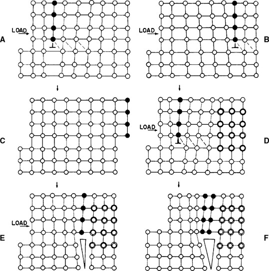
FIGURE 6-6 Sketches showing plastic shearing with crack formation at the site of an impurity (dark, open circles). Without the impurity (A, B, C), the load forces the dislocations completely through the lattice without fracture (note the progression of solid dark circles from left to right). However, when the impurity is present (D, E, F), it stops the progress of the dislocation. As other dislocations build up, the lattice below them cannot accommodate and a crack forms in the lattice (E). In E, note the broken bonds between atoms. Once formed, a crack can grow rapidly and relatively easily and lead to catastrophic failure.
ALLOYS AND PRINCIPLES OF METALLURGY
Metals can be mixed together much as liquids are. A mixture of metals is called an alloy, and the study of metals and alloys is called metallurgy. Alloys may be a mixture of as few as two or (in the case of dental casting alloys) as many as nine or more different metals. As with liquids, not all metals will dissolve in one another freely; some metals will not dissolve at all into other metals. The concept of phases and phase diagrams was developed to help explain the nature of alloys and metal solubility. Alloys may have crystal structures like the pure metals previously discussed, or they may have other atomic structures, such as eutectics or intermetallic compounds. These concepts will be discussed later in this chapter.
PHASE DIAGRAMS AND DENTAL ALLOYS
A phase is a state of matter that is distinct in some way from the matter around it. In a mixture of ice and water, there are two phases because although ice and water are the same chemically, they each have distinct arrangements of atoms. Ice has the crystalline arrangement of a solid, whereas water has the random atomic arrangement of a liquid. A solid dental alloy may also have one phase if the composition of the alloy is essentially homogeneous throughout. If the alloy has areas where compositions are different, it is called a multiple-phase alloy. The distinction between single- and multiple-phase alloys is important to the strength, corrosion, biocompatibility, and other alloy properties.
Phase diagrams are “maps” of the phases that occur when metals are mixed together. If there are two metals in an alloy, a binary phase diagram is used. If three metals are in the alloy, a ternary phase diagram may be used. Phase diagrams describing alloys with more than three metals are not used because they are too complex; the vast majority of phase diagrams describe only binary alloys. For dental alloys that contain four or more metals, the binary phase diagram of the two most abundant metals in the alloy typically describes the alloy. In practice, phase diagrams are determined by meticulous examination of a series of binary alloys cooled slowly and monitored for composition.
A typical phase diagram for a theoretical binary alloy AB is shown in Fig. 6-7. The x-axis describes the composition of the elements in either weight percent (wt%) or atomic percent (see Chapter 15). The y-axis is the temperature of the alloy system. It is important to remember that a phase diagram shows the composition and types of phases at a given temperature and at equilibrium. Every phase diagram divides an alloy system into at least three areas: the liquid phase, the liquid-solid phases, and the solid phase. For example, everything above the temperatures shown by line ACB in Fig. 6-7 is liquid. This line is therefore called the liquidus. Everything below line ADB is solid. This line is thus called the solidus. The area between these two lines contains some liquid and some solid. At 0% B, a single phase exists (100% A) that has a single melting point (800° C). At 100% B, a single phase exists that has a single melting point (210° C). At any composition between these extremes, the melting range is defined as the temperature difference between the liquidus (ACB) and solidus (ADB).
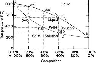
FIGURE 6-7 A phase diagram for two theoretical components A and B. The liquidus for this system follows the line ACB. The solidus follows ADB. The melting points for each pure metal occur at A and B.
The phase diagram can also be used to find the composition of liquid and solid between the liquidus and solidus (see Fig. 6-7). Consider an alloy that is 20% B (and 80% A) at a temperature of 800° C. This alloy is all liquid. When the temperature drops to 700° C and the system equilibrates, there will be some liquid and some solid. If a line parallel to the x-axis is projected at 700° C to the liquidus, the composition of the liquid can be determined by projecting down to the x-axis. In this case, the liquid will be 60% A (and 40% B). By projecting at 700° C to the solidus then to the x-axis, the composition of the solid is 10% B (and 90% A). Below about 540° C, the alloy is 80% A and 20% B, or all solid. Thus, the phase diagram can map the types and compositions of phases at any temperature and over any alloy composition.
When metals are mixed together in the molten state, then cooled to the solid state, there are several outcomes depending on the solubility of the metals in each other. If the metals remain soluble in one another, the result is a solid solution. If the metals are not soluble in the solid state, then a eutectic may form. Sometimes, the elements react to form a specific compound, called an intermetallic compound. The phase diagrams that describe these outcomes will be presented in the following paragraphs.
Solid Solution Alloys
Fig. 6-8 shows a series of binary alloys of Au and Cu. Because there is only a single phase below the solidus (S), this is a solid solution alloy system, common in dental casting alloys. Au and Cu are miscible; that is, they are soluble in any combination. If one were to examine the crystal structure of this alloy, the Au atoms would occupy some the positions of the face-centered cubic structure and the Cu atoms would occupy others. The relative positions of the Au and Cu atoms would be random, however. The solid solution system (see Fig. 6-8) is also characterized by a series of melting ranges that are more or less a smooth transition between the two melting points of the pure elements. The temperature distance between the liquidus and solidus determines the melting range; it is characteristic for each alloy system and varies with the composition within a system.
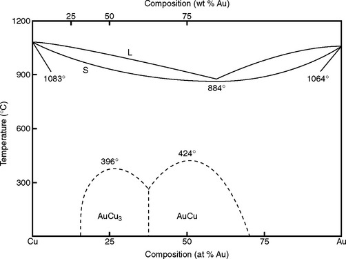
FIGURE 6-8 The Au-Cu binary phase diagram illustrates well the principles of a solid solution alloy system. The Au and Cu are miscible (completely soluble in one another), thus there is only one solid phase for any composition of Au and Cu. The liquidus is indicated by L, the solidus by S. Au and Cu occupy random positions in the crystal lattice at all compositions except under the dotted lines. Within the dotted lines, there are specific patterns to the Au and Cu atoms in the lattice, hence the name ordered solution.
The Au-Cu system (see Fig. 6-8) also has several dotted lines below the solidus for alloy compositions between 20 and 70 atomic percent Au. These lines indicate the formation of ordered solutions. In ordered solutions, the Au and Cu atoms still occupy the face-centered cubic positions, but in a specific pattern that depends on the composition. Ordered solutions impart higher hardness and strengths to alloys (see Chapter 15).
Eutectic Alloys
Fig. 6-9 shows a series of binary Ag-Cu alloys. In this phase diagram, the liquidus and solidus meet at a mid-range composition and the solidus is lower (at 779.4° C) than either pure Ag (960.5° C) or pure Cu (1083° C). This liquidus-solidus configuration is characteristic of a eutectic alloy system. The Ag-Cu system is especially important in high-Cu dental amalgam, but is also important in the formulation of some dental casting alloys.
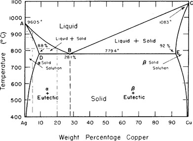
FIGURE 6-9 A eutectic alloy system occurs when two metals are soluble as liquids but nearly insoluble as solids. These systems have a single composition (the eutectic composition) with a melting point that is lower than either component metal. These principles are illustrated well by the Ag-Cu eutectic system. The liquidus (ABC) and solidus (ADBEC) meet at the eutectic composition (B), which is 28.1 wt% Cu with a melting point of 779.4° C. At other compositions, the solid contains two phases: a solid solution (either α or β) plus the eutectic. Note that below 400° C, almost no composition will support a single-phase composition, because the Ag and Cu are not soluble in each other below this temperature.
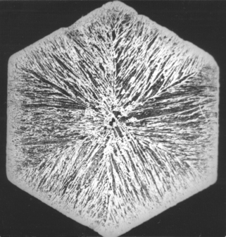
The eutectic system shown in Fig. 6-9 contains a pure solid solution below 400° C only at either extreme of composition (<1% Ag or <1% Cu) because the Ag and Cu are essentially insoluble in one another in the solid state. At all other equilibrium conditions below the solidus, a mixture of a solid solution (either α or β) and the eutectic composition occurs. The eutectic composition is 28.1% Cu (and 71.9% Ag) and has a layered appearance under a light microscope (Fig. 6-10). If the alloy is at the eutectic composition, all the alloy will be in the eutectic phase at room temperature (see the dotted line in Fig. 6-9). If the composition is other than this, then the alloy will be some combination of the solid solution and eutectic phases. The exact proportions of eutectic and solid solution can also be determined from the phase diagram, but this calculation is beyond the scope of this discussion. Finally, note that a pure eutectic composition has a melting point (as opposed to a melting range) that is substantially lower than either of the pure components. The eutectic system of Pb-Sn uses the eutectic alloy composition as plumber’s solder because of its low melting point.
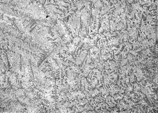
FIGURE 6-10 A microscopic view of a Ag-Cu eutectic mixture (28.1 wt% Cu and 71.9 wt% Ag) magnified ×50. The eutectic composition is a fine layering between Ag and Cu. This layering is a result of the insolubility of Ag and Cu in the solid condition. This eutectic has a melting point rather than a melting range, as indicated on the phase diagram shown in Fig. 6-9.
Intermetallic Compounds
If two metals react to form a new compound with a specific composition, the phase diagram reflects an intermetallic compound. Fig. 11-2 shows the formation of the intermetallic compound Ag3Sn in the Ag-Sn alloy system. Ag3Sn is a fundamentally important intermetallic compound in dental amalgam. The Ag-Sn phase diagram is extremely complex and its complete description is beyond the scope of this discussion. However, the intermetallic compound is seen in Fig. 11-2 at 26.8 wt% of Sn as a solid vertical line extending to room temperature.
Ternary Phase Diagrams
It is possible to construct a phase diagram for a ternary alloy (with three components). These phase diagrams are three-dimensional, as shown in Fig. 6-11. Two-dimensional representations in the shape of an equilateral triangle are also used to represent the three-dimensional structure. The ternary phase diagrams are difficult to prepare and interpret; their detailed description can be found in engineering and metallurgy texts.
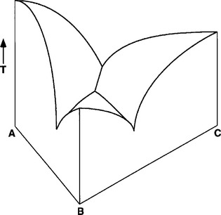
FIGURE 6-11 Ternary phase diagram showing the liquid-solid surface formed between components A, B, and C. The vertical axis represents increasing temperature (T). The AB, AC, and BC axes reflect concentrations of the components. The three-dimensional surface that is visible represents the liquidus for this system. Other features of the phase diagram below the liquidus require a two-dimensional cross section parallel to the ABC plane. The shape of the liquidus indicates that this is a eutectic system.
ALLOY MICROSTRUCTURE
The internal appearance of alloys under light and electron microscopy has been extensively used to describe alloys and interpret alloy behavior. Atomic structure can be determined by x-ray diffraction or high-resolution electron microscopy. Alloy microstructure is viewed by polishing the alloy surface, then etching with an acid to bring out relevant features. The microstructure of any alloy is a consequence of the chemistry and thermodynamics governing the elements involved.
Grains, Grain Boundaries, and Dendrites
When a molten alloy is cooled, the first solid alloy particles form as the temperature reaches the liquidus. This process is called nucleation. In some alloys, fine particles of a high-melting point element such as Ir are added to encourage uniform nucleation throughout the alloy. These particles, used in this manner, are called grain refiners. As cooling continues, the nuclei grow into crystals called grains, and the grains enlarge until all of the liquid is gone and the grains meet and form boundaries between each other (at the solidus temperature). At this point, the grains are visible under a light microscope (Fig. 6-12) and are sometimes large enough to be seen with the unaided eye. The size of the grains depends on the cooling rate, alloy composition, presence of grain refiners, and other factors. Grain size may influence an alloy’s strength, workability, and even susceptibility to corrosion (see Chapter 15). The junctions between grains are called grain boundaries. Grain boundaries are important because they often contain impurities such as oxides and are a site of corrosive attack. The grain boundaries are clearly visible in light microscopic views of alloys (see Fig. 6-12).
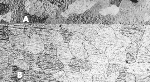
FIGURE 6-12 Typical grain structure of pure gold (A) and 22-carat Au-Cu alloy (B) viewed at low magnification. Each grain is separated from other grains by grain boundaries (dark lines) and is a single metallic crystal. The grains have different shades because each crystal has a different orientation and therefore reflects light differently. Several inclusions (small dark dots) are also visible. These may represent impurities or voids.
Dendrites result from grains that grow along major axes of the crystal lattice (Fig. 6-13) early in the freezing process. The dendritic skeleton structure persists to room temperature if the cooling rate of the alloy is too fast to allow equilibrium to occur. The dendritic structure is common in dental alloys and can be seen after etching and polishing the alloy (Fig. 6-14). Dendritic structure indicates that the alloy is not at equilibrium and its presence can increase the corrosion of the alloy.
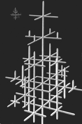
FIGURE 6-13 Sketch of a dentritic structure of a crystal. The crystal grows preferentially in the x-, y-, or z-axis due to the cooling of the alloy mass. If the cooling rate is fast enough, the dendrites will have a composition slightly different from the rest of the alloy because the equilibrium concentration specified by the phase diagram will not have had time to occur.
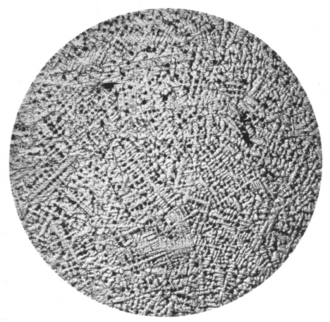
FIGURE 6-14 Dendritic structure visible in a low-power light microscopic view of a gold alloy (polished, acid-etched). The treelike branching is similar to that sketched in Fig. 6-13.
Cast Microstructure
Cast alloy microstructures have several distinguishing characteristics. Grains are usually visible and take on the appearance in Fig. 6-12. The size of the grains may be large or small depending on the cooling rate and other factors mentioned previously. A slow cooling rate and few impurities generally lead to large grains. Faster cooling rates or the presence of grain refiners lead to smaller grains. Grains that are uniform in size and shape throughout the alloy are described as equiaxed. Fine-grained (equiaxed) alloys are generally more desirable for dental applications because they have more uniform properties (see Chapter 15). Different phases of a multiple-phase alloy may also be seen in cast microstructure.
Other factors may influence cast microstructure. Insoluble impurities in an alloy may be detected at grain boundaries. Defects such as gas inclusions may cause small pits in the bulk of an alloy or at the surface. In the body of an alloy, pits may concentrate the stress and contribute to restoration failure. At the surface, pits may enhance corrosion, tarnish, or discoloration from the accumulation of organic debris. Voids in an alloy may result from improper cooling or improper investing (see Chapter 17 on Casting).
When a mass of molten metal is cast into a cold mold, the metal at the mold wall freezes first, and grains form and grow from the walls of the mold to the center of the mass. This type of grain growth is called columnar growth and can lead to alloy weakness from interference boundaries between the converging grains (Fig. 6-15). In general, it is more desirable to have the alloy freeze in a less ordered fashion. Sharp corners in any casting mold can enhance columnar grain growth and are generally undesirable.
Cold-Worked (Wrought) Microstructure
Metals and alloys are cast for two quite different purposes. In one instance, the casting serves as the final structure. In the second, it serves as an object that is further manipulated to form wires, sheets, bars, or similar fabricated structures. A typical cast structure in dentistry is an inlay or bridge restoration, which is not given further mechanical treatment except for polishing or marginal adaptation by hand operations. This limited treatment does not significantly modify the microstructure of the casting. Such a casting is designed to form to precision measurements, and the properties of the structure are those displayed by the cast metal or alloy.
When the metal is to be used for wires, bands, bars, or other types of wrought structures, it is first cast into ingots that are then subjected to rolling, swaging, or wire-drawing operations that produce severe mechanical deformation of the metal. Such operations are described as hot or cold working of the metal, depending on the temperature at which the operation is performed. Many dental structures, such as orthodontic wires and bands, are formed by cold-working operations. The finished product is often described as a wrought structure to denote that it has been formed by severe working or shaping operations. The properties of wrought structures are quite different from those of cast structures in both internal appearance and mechanical characteristics.
The microscopic appearance of a cast metal is crystalline and sometimes has dendritic structure, as shown in Fig. 6-16. When this metal is subjected to cold-working operations, such as drawing into a wire, the grains are broken down, entangled in each other, and elongated to develop a fibrous structure or appearance that is characteristic of wrought forms, as shown in Fig. 6-17. This change in internal appearance is accompanied by a change in mechanical properties. In general, mechanical properties of the wrought structure are superior to those of a casting prepared from the same melt or alloy. It should be emphasized that in cast dental structures such as inlays, the mechanical properties of strength and hardness are not modified appreciably by simple polishing or marginal adaptation operations.
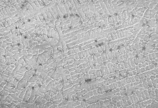
FIGURE 6-16 Low-power light microscopic view of the typical grain structure of a cast gold alloy. Compare this grain structure to the same alloy after it has been pulled into wire form (see Fig. 6-17).
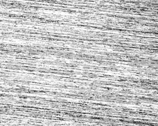
FIGURE 6-17 Low-power light microscopic view of a wrought wire microstructure. The grains visible in Fig. 6-16 have been broken apart and tangled among one another. The entangled grains are lined up along the axis of the wire. This type of microstructure is called a fibrous structure.
Recrystallization and Grain Growth
Metals or alloys that have been cold-worked in the process of forming wires or bands change their internal structure and properties when heated or annealed. The characteristic fibrous structure of the wrought mass is gradually lost, and the grain or crystalline structure reappears. The process is known as recrystallization or grain growth. The degree of recrystallization is related not only to the alloy composition and mechanical treatment or strain hardening received during fabrication, but also to the temperature and the duration of the heating operation. High temperatures and long heating periods produce the greatest amount of recrystallization. It is not uncommon to find that during a soldering or annealing operation of a practical appliance, the temperature applied to the wire or band materials is sufficient to cause recrystallization of the wrought structure. Recrystallization of a segment of wire adjacent to a solder joint is shown in Fig. 6-18. Because the strength is usually reduced in recrystallized wrought structure (ductility often increases), it is necessary to guard against excessive heating during the assembly of a wrought metal appliance. Although the tendency for crystallization is more prevalent in some wires than others, it can be kept to a minimum when the time and temperature of heating are kept as low as possible.
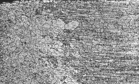
FIGURE 6-18 The right side of this light microscopic view shows the fibrous microstructure typical of a wrought wire. Heat was applied to this wire from the left side, perhaps in a soldering operation, and the fibrous structure has been lost and replaced with the typical grain pattern of a cast structure. If more heat were applied, then the entire wire would revert to the cast structure. Such a conversion will cause the wire to be weaker but it will have a higher ductility. Because the wrought form was selected for its strength properties, the recrystallization shown here is not clinically desirable.
Although there is probably some tendency for cast metal structures to recrystallize when heated after casting, grain growth does not become evident when the structure is heated within the range of practical operations. Under excessive conditions of heating there is some evidence of recrystallization in cast alloys, but the significance is not so pronounced as in the case of wrought forms. Within practical limits of operation, therefore, this characteristic of recrystallization and grain growth is limited to wrought structures.
The cause for grain growth in the wrought structure is related to the tendency for metals to maintain a crystalline internal orientation of the component atoms. During the formation of the wrought structure, the original grains produced during the crystallization of the original casting are deformed and broken into small units. The deformation of the metal mass occurs by slippage of one portion past another along definite crystallization planes. The deformation and slippage occur in various directions to distort the grain boundaries. The greater the degree of cold working, the greater is the degree of grain boundary deformation. This deformed structure is unstable in nature, with greater internal energy than one that is in the cast condition. Accordingly, it possesses modified physical properties and has the tendency to recrystallize when heated.
Stress relieving, annealing, recrystallization, and grain growth can be illustrated by the series of sketches shown in Fig. 6-19. A wrought wire that has been bent beyond the proportional limit and that contains tensile and compressive stresses at the upper and lower boundaries is shown in Fig. 6-19, A; the wire has the typical fibrous structure and a deformed crystal lattice. Moderate temperatures cause the release of these stresses, as shown in Fig. 6-19, B, without other changes. Higher heating at annealing temperatures (Fig. 6-19, C) causes the disrupted crystal structure to contain sufficient energy to return to its normal crystal structure, but the fibrous wrought structure is still evident; under this condition the corrosion resistance is increased. Further increases in temperature or time, or both, as seen in Fig. 6-19, D, permit recrystallization with grains appearing and the fibrous structure disappearing. Finally, in Fig. 6-19, E, grain growth occurs, and the cast condition again dominates the microstructure.
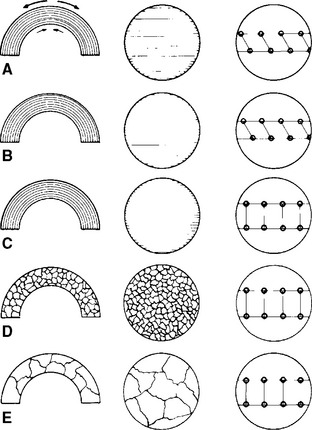
FIGURE 6-19 Sketches depicting the gross view (left column), microstructure (middle column), and crystal view (right column) of wrought wire that has been bent. A, The fibrous microstructure is present and arrows indicate residual stresses. B, Minimal heat leaves the fibrous structure intact but relieves the stresses. However, the lattice remains distorted. C, Annealing with more heat allows the lattice deformation to be relieved. The fibrous microstructure remains. D and E, Further heating causes a loss of the fibrous structure and growth of the grains, which increase in size with increasing application of heat.
PROPERTIES OF ALLOYS
Dental alloys are diverse and use a wide variety of metallic elements and some of the metalloids (see Fig. 6-1). The compositions of dental alloys are dependent on the clinical use and environment for an alloy. Thus a carbide bur needs to be very hard to cut tooth structure, but its intraoral corrosion is of little concern. A dental crown must have excellent corrosion resistance and must not deform permanently. Endodontic files need to have moderate moduli and resist torsional and bending failure. In each case, the alloys contain elements that optimize the specific properties that are needed most for clinical success. In dentistry, solid solutions, eutectics, and intermetallic compounds and wrought alloys are used. It is the diversity of possible properties that makes alloys suitable for many clinical dental applications.
ALLOY STRENGTHENING MECHANISMS
Alloys generally require high strength and hardness to be useful in dental applications. Several metallurgical strategies are used to strengthen alloys to appropriate levels. Nearly all these strategies share the goal of impeding the deformation of the alloy by the dislocation mechanism (see previous discussion, this chapter).
Solid solutions are generally stronger and harder than either component pure metal. The presence of atoms of unequal size makes it more difficult for atomic planes to slide by each other. Even small differences in atomic size can strengthen alloys by the solid solution mechanism. Ordered solutions act to further strengthen a solid solution by providing a pattern of dissimilar sizes throughout the alloy’s crystal structure. Solid and ordered-solution strengthening are very common in dental casting alloys.
Precipitation hardening is another strategy used to strengthen dental alloys. By heating some cast alloys carefully, a second phase can be made to appear in the body of the alloy. The new phase blocks the movement of dislocations, thereby increasing strength and hardness. The effectiveness of precipitation hardening is greater if the precipitate is still part of the normal crystal lattice. This type of precipitation is called coherent precipitation. Overheating may reduce alloy properties by allowing the second phase to grow outside the original lattice structure. Fig. 6-20 shows the character of a casting alloy that was strengthened by the addition of as little as 0.08 wt% iron to a gold-platinum alloy. The iron formed an FePt3 precipitate and the hardness of the alloy tripled under appropriate conditions.
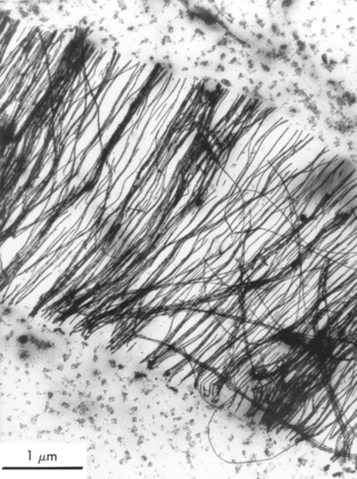
FIGURE 6-20 Electron micrograph of FePt3 (black, hairlike structures) formed in a gold-platinum alloy containing 0.08 wt% iron. (From Sims JR Jr, Blumenthal RN, O’Brien WJ: J Biomed Mater Res 7:497, 1973.)
Other factors may increase alloy strength and hardness. Grain refiners such as Ir, Rh, and Ru improve the strength of alloys by several times. Moreover, strength and hardness are generally improved without sacrificing ductility. Fine-grained alloys have grain sizes below 70 μm in diameter. Cold-working an alloy will significantly strengthen it. Cold-working works out the dislocations, thereby making further deformation more difficult. However, cold-working will also embrittle an alloy by making it less ductile.
PROPERTIES OF CASTING ALLOYS
In general, the properties of the solid solutions resemble those of the metals forming the alloy, with certain exceptions. Solid solution alloys often have higher strength and hardness and lower ductility than either pure metal. This is the basis of solid-solution strengthening. Solid solutions also possess melting ranges rather than melting points and always melt below the melting point of the highest points of both metals. These alloys are commonly used in dentistry because they have higher corrosion resistance than multiple-phase alloys. Also, in a few cases, solid solutions have higher corrosion resistance than the pure metals. A notable example is the addition of chromium to iron in solid solution to make the corrosion-resistant alloy “stainless steel.” However, in the case of gold, adding other elements reduces the corrosion resistance.
Eutectic mixtures are usually harder and stronger than the metals used to form the alloy and are often quite brittle. They possess a melting point at the eutectic composition, not a melting range, and any other combination of the alloy system has a higher fusion temperature than the melting point of the eutectic mixture. Eutectic mixtures, along with other multiple-phase microstructures, often have poor corrosion resistance. Galvanic action between the two phases at a microscopic level can accelerate corrosion, as described in Chapter 3.
The intermetallic compounds formed in some alloy systems are usually very hard and brittle. Their properties rarely resemble those of the metals making the alloy. For example, Ag2Hg3 is an intermetallic compound formed in dental amalgam that has properties completely different from those of pure silver or mercury.
PROPERTIES OF WROUGHT ALLOYS
Compared with their cast counterparts, wrought alloys generally have high strengths and hardness. Ductility, on the other hand, decreases with cold work. Clinically, this loss of ductility can be a problem. For example, cast clasps on removable partial dentures may fail if multiple adjustments are made to a clasp (see Chapter 16). Cast properties can be regained by heating the wrought form sufficiently to allow recrystallization and grain growth.
Anusavice, KJ. Phillips’ science of dental materials, ed 11. St Louis: Saunders, 2003.
Craig, RG, Powers, JM, Wataha, JC. Dental materials: properties and manipulation, ed 8. St. Louis: Mosby, 2004.
Dieter, G. Mechanical metallurgy, ed 3. New York: McGraw-Hill, 1986.
Flinn, RA, Trojan, PK. Engineering materials and their applications, ed 4. New York: John Wiley & Sons, 1990.
Fontana, MG. Corrosion engineering, ed 3. New York: McGraw-Hill, 1986.
Gettleman, L. Noble alloys in dentistry. Current Opinion Dent. 1991;2:218.
Leinfelder, KF. An evaluation of casting alloys used for restorative procedures. J Am Dent Assoc. 1997;128:37.
Malhotra, ML. Dental gold casting alloys: a review. Trends Tech Contemp Dent Lab. 1991;8:73.
Malhotra, ML. New generation of palladium-indium-silver dental cast alloys: a review. Trends Tech Contemp Dent Lab. 1992;9:65.
Mezger, PR, Stolls, ALH, Vrijhoef, MMA, et al. Metallurgical aspects and corrosion behavior of yellow low-gold alloys. Dent Mater. 1989;5:350.
Moffa, J. Alternative dental casting alloys. Dent Clin North Am. 1983;27:733.
Morris, HF, Manz, M, Stoffer, W, et al. Casting alloys: the materials and the “clinical effects,”. Adv Dent Res. 1992;6:28.
O’Brien, WJ. Dental materials and their selection, ed 2. Carol Stream, IL: Quintessence, 1997.
Pourbauix, M. Electrochemical corrosion of metallic biomaterials. Biomaterials. 1984;5:122.
Vermilyea, SG, Cai, Z, Brantley, WA, et al. Metallurgical structure and microhardness of four new palladium-based alloys. J Prosthodont. 1996;5:288.
Wendt, SL. Nonprecious cast-metal alloys in dentistry. Current Opinion Dent. 1991;1:222.