Breathing Circuits
CLASSIFICATIONS OF BREATHING CIRCUITS
Chemical Absorption of Carbon Dioxide
Use of Valves to Separate Exhaled Gases from Inhaled Gases
Use of Open-Drop Ether or a T-Piece Without a Reservoir to Release Exhaled Carbon Dioxide into the Atmosphere
The Anesthesia Machine
The anesthesia machine serves to create a desired mixture of anesthetic gases, vapors, oxygen, and air (as well as other gases such as helium and carbon dioxide, albeit less frequently). The patient is the recipient of these prepared gas mixtures of known composition, and the breathing circuit is the interface between the anesthesia machine and the patient. This circuit delivers the gas mixture from the machine to the patient as it removes carbon dioxide, excludes operating room (OR) air, and conditions the gas mixture by adjusting its temperature and humidity. It converts continuous gas flow from the anesthesia machine to the intermittent flow of breathing, facilitates controlled or assisted respiration, and provides other functions such as gas sampling and pressure and spirometric measurements.
The desirable characteristics of a breathing circuit include 1) low resistance to gas flow, 2) minimal rebreathing of the preceding alveolar expirate, 3) removal of carbon dioxide at the rate at which it is produced, 4) rapid changes in delivered gas composition when required, 5) warmed humidification of the inspirate, and 6) safe disposal of waste gases. The components of a breathing circuit include the breathing tubing; respiratory valves; reservoir bags; carbon dioxide absorption canisters; a fresh gas inflow site; a pop-off valve leading to a scavenger for excess gas; a Y-piece with a mask or tube mount; and a face mask, laryngeal mask, or tracheal tube. Other devices that may be included are filters; humidifiers; valves for positive end-expiratory pressure (PEEP); and detecting mechanisms for airway pressure, spirometry, and gas analysis. Although these circuit components can be assembled in many ways, contemporary systems are usually configured by the manufacturer and permit little intervention by the user in regard to their configuration. Understanding the advantages and limitations of the different configurations allows the user to select the most appropriate type for varying clinical settings.
History of Device Development
Breathing circuits have been an important concern from the start. Because of a delay in the production of his inhaler, Morton was late to his first public exhibition of the “Somniferon” (ether) in 1846. The earliest circuits were mechanically simple; differences among them were related to the characteristics of the primary anesthetic agent. Because nitrous oxide and ether anesthetic mixtures were weak (less potent) or slow to produce anesthesia, it was necessary to exclude air and helpful to include oxygen enrichment. The rapid onset of action and potency of chloroform, on the other hand, demanded precise control. It became apparent that the unique features of each agent were important. The ability to assist respiration was advantageous, as was conservation of costly agents and avoidance of large leaks of flammable ones.
In the twentieth century, a large number of relatively small but more highly engineered improvements were made as other demands on the breathing circuit were recognized. In 1915, Dennis Jackson described the first carbon dioxide absorber to save on the cost of nitrous oxide for animal studies.1 Ralph Waters brought the idea into the OR, designing a to-and-fro absorption canister that used soda lime.2,3 Bryan Sword introduced the first circle breathing circuit in 1930.4 Thus low-flow absorption systems were already in use when cyclopropane made them essential. A return to high flows in the United States was brought about by the poor performance of vaporizers for halothane in the 1950s, with the demonstration that such flows could eliminate carbon dioxide without the use of soda lime.5,6
Stimulated by Magill’s use of a number of pieces of apparatus put together in differing configurations for differing purposes, Mapleson described a variety of Magill circuits.7 The original Ayre’s T-piece was modified by numerous practitioners; the Jackson-Rees circuit represents one such example.8 A variety of proprietary nonrebreathing valves were introduced, and the circuits named for them included the Stephen-Slater,9 the Fink,6 the Ruben,10 and the Frumin.11
Partial rebreathing and functionally nonrebreathing circuits—such as the Bain,12 Humphrey ADE,13 and Lack14 systems—found various proponents. Ingenious switching valves permitted transfiguration from one circuit to another,13 which led to difficulty in remembering which circuit was optimal for what purpose.
Today, in addition to factors of convenience and economy, circuits are used to control heat and humidity; to measure patient variables such as tidal volume, respiratory frequency, airway pressure, and inspired and expired gas concentrations; and to control contamination of the OR environment by the agents themselves. The 150-year history of the development of the breathing circuit offers the practitioner a number of choices. All commonly used circuits accomplish their goals more or less equivalently, but the simple act of increasing fresh gas flow, for example, may markedly increase the work of breathing.15 Therefore it is vital that the anesthesiologist understand the functional characteristics of each circuit.
Classifications of Breathing Circuits
A widely used nomenclature was developed that classified circuits as open, semiopen, semiclosed, or closed, according to whether a reservoir is used and whether rebreathing occurs. An open system has no reservoir and no rebreathing; a semiopen system has a reservoir but no rebreathing; a semiclosed system has a reservoir and partial rebreathing; and a closed system has a reservoir and complete rebreathing. Variations on this classification included the type of carbon dioxide absorber and unidirectional valves used.
Because of confusion with this traditional nomenclature, Hamilton recommended its abandonment in favor of both a description of the hardware (e.g., circle filter system, coaxial circuit, T-piece) and the gas flow rates being used.16 Identifying the circuits by eponym—such as Adelaid, Bain, Hafnia, Humphrey, Jackson-Rees, Lack, Magill, and Waters—did not help in understanding the function or application of the circuit. Almost all anesthesia machines are equipped with some form of a circle breathing circuit with the ability for carbon dioxide absorption during low-flow anesthesia and elimination through the pop-off valve during high-flow anesthesia. Because an understanding of how circuits work is essential, breathing circuits in this chapter are organized by method of carbon dioxide elimination. Methods for removal of carbon dioxide are discussed.
Chemical Absorption of Carbon Dioxide
Semiclosed and closed systems (i.e., circle and to-and-fro) rely on chemical absorption of carbon dioxide. Exhaled carbon dioxide is absorbed, and all other exhaled gases are rebreathed. The quantities of fresh oxygen and anesthetics equal those lost as a result of uptake, metabolism, and circuit leaks.3,17,18
Dilution with Fresh Gas
Because of the intermittent nature of carbon dioxide excretion (during exhalation only) and the continuous inflow of fresh gas, the choice of inflow rate—as well as the locations of the inflow site, reservoir bag, and pop-off valves—contributes to the efficiency of carbon dioxide removal. When fresh gas flows are 1 to 1.5 times the minute volume (approximately 10 L/min in an adult), dilution alone is sufficient to remove carbon dioxide.17,19-23 Such systems then behave the same as a nonrebreathing system.
Use of Valves to Separate Exhaled Gases from Inhaled Gases
Systems that use nonrebreathing valves are examples of this method of carbon dioxide removal.6,9,11,24,25 A circuit that by virtue of high flows behaves as if it were nonrebreathing is not considered a nonrebreathing circuit in this analysis.
Use of Open-Drop Ether or a T-Piece Without a Reservoir to Release Exhaled Carbon Dioxide into the Atmosphere
Although similar to the second method above, systems that used open-drop ether or a T-piece without a reservoir were not truly breathing circuits. The T-pieces with an expiratory reservoir rely on dilution of carbon dioxide by both fresh gas and room air for its removal; these have been included in semiclosed circuits below.26
Components of A Breathing Circuit
The circuits described above have many features in common; they connect to the patient’s airway through a face mask, laryngeal mask, or tracheal tube adapted to the breathing circuit through a Y-piece or elbow. The system may include valves to permit directional gas flow, and a reservoir bag is almost always present, which can be used to manually force gas into the lungs. Fresh gas must be supplied to the circuit, and excessive gas must be allowed to escape. In some, carbon dioxide is absorbed in a chemical filter. A variety of ancillary devices may also be present, such as humidifiers, spirometers, pressure gauges, filters, gas analyzers, PEEP devices, waste gas scavengers, and mixing and circulating devices.
Connection of the Patient to the Breathing Circuit
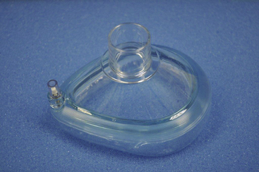
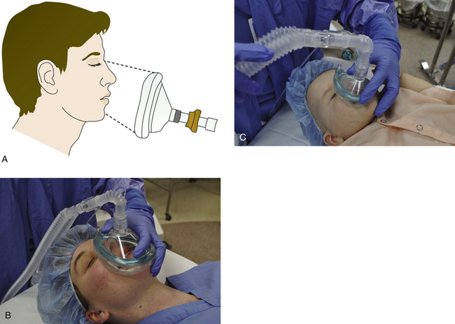
Either an anesthesia mask, supraglottic device, or a tracheal tube connects the circuit to the patient. Masks are made from rubber or clear plastic to make secretions or vomitus visible (Fig. 4-1). Most have an inflatable or inflated cuff, a pneumatic cushion that seals to the face. Masks are available in a variety of sizes and styles to accommodate the wide variety of facial contours. For example, a prominent nasal bridge may prevent a tight fit if the mask’s cuff is flat at that point. A prominent chin (mentum) with sunken alveolar ridge causes a leak at the corner of the mouth, and the volume of the mask contributes to apparatus dead space. The mask should fit between the interpupillary line over the nose and in the groove between the mental process and the alveolar ridge (Fig. 4-2). The average length of this area is 85 to 90 mm in adults. The newest disposable plastic masks are available in a wide range of sizes, intended to fit the faces of small children and large adults equally well. Choosing from a selection of mask sizes and styles is more rational than a “one size fits all” approach because a poorly fitting mask can result in trauma to the patient. This is especially true when the mask must be positioned above the eyebrows because it can cause pressure on, and possibly damage to, the optic and supraorbital nerves. Masks often have a set of prongs for attachment to a rubber mask holder or head strap; however, if pulled too tight, this mask holder may obstruct the airway. Masks connect to the Y-piece or elbow via a 22-mm (⅞-inch) female connection.
Breathing Tubing
The tubing used in breathing circuits typically is approximately 1 meter in length, has a large bore (22 mm) to minimize resistance to gas flow, and has corrugations or spiral reinforcement to permit flexibility without kinking. The internal volume is 400 to 500 mL/m of length. Although these tubes were formerly made of conductive rubber, disposable plastic tubing has almost completely replaced rubber. Electrical conductivity is no longer necessary when breathing tubing is used with nonflammable agents. The advantage of plastic is that it is lightweight; however, it is not biodegradable and thus is disposable by design although not by use. Plastic tubing for a breathing circuit is supplied sterile despite the lack of convincing epidemiologic data to support the necessity of sterile tubing.27,28 On occasion, it is necessary to pass a breathing circuit on to the sterile surgical field (e.g., during an ex utero intrapartum treatment procedure). By convention, the ends of the tubing are 22 mm in internal diameter (ID) and are identical in design. Tubing should be inspected before use because manufacturing errors can result in obstruction of the lumen.29,30 Compliance of the tubing varies from nearly 0 to more than 5 mL/m/mm Hg of applied pressure, and plastic tubing has lower values than rubber (Table 4-1). Apparent distensibility is even greater because compression of gas under pressure, to the order of 3% of the volume, occurs at typical inflation pressures. Inflation of a patient’s lungs to 20 cm H2O peak inspiratory pressure compresses 30 to 150 mL of gas in the tubing.31 This volume is not delivered to the patient’s lungs, but some fraction of it may be measured by a spirometer within the circuit, adding a form of apparatus dead space to the system. The exact fraction depends on where the spirometer is placed in the circuit with respect to the unidirectional valves.
TABLE 4-1
Compliance of Ohio Anesthesia Breathing Circuits
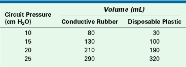
From Fluidically controlled anesthesia ventilator operation and maintenance manual. 1974, Ohio Medical Products (now GE Healthcare, Waukesha, WI).
Resistance to gas flow in standard, corrugated breathing tubes is exceedingly small—less than 1 cm H2O/L/min of flow.32 When it is desirable to have the anesthesia machine at some distance from the patient’s head, several tubes may be connected in series with connectors 22 mm (⅞ inch) in outside diameter (OD). Alternatively, extra-long tubing is available, including tubing that can be compressed to 200 mL of volume in approximately 50 cm of length or that can be stretched to nearly 2 m with an 800-mL volume. These “concertina” extensions do not increase the resistance of the system by any appreciable amount and affect the apparatus dead space only by their compliant volume (Fig. 4-3).
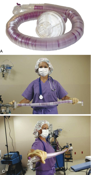
FIGURE 4-3 “Concertina” style breathing circuit tubes can be or compressed (A and B) or stretched (C) to change in length and volume without significantly affecting apparatus dead space. (Courtesy King Systems, Noblesville, IN.)
The pattern of gas flow through the circuit is almost always turbulent because of the corrugations in the tubing, which promote both radial mixing and longitudinal mixing. In documenting performance of one circuit, Spoerel33 demonstrated complete mixing of dead space and alveolar gas after gas had passed through 1 m of such tubing. A change in gas composition at one end, such as when the delivered gas is altered at the anesthesia machine, completes a change in the inspired concentration at the patient connection within two to three breaths. The change in inspired concentration is nearly exactly the change in delivered concentration when high fresh gas flows are used (≥10 L/min). The change decreases to nearly imperceptible as inflow is decreased toward that of closed systems.
Lengths of breathing tubing are sometimes used to connect ventilators to the bag mount and to connect to scavenging devices. Optimally, either a 19- or 30-mm diameter ends on the scavenger mounts prevent inappropriate connections. Tubing of smaller diameter is made for use in circle systems designed specifically for infants and children, and their resistance to gas flow is insignificantly increased. With less compression volume, measured ventilation is more accurate.
Reusable rubber tubing is connected to the mask or tube by a separate Y-piece. Disposable sets often incorporate a Y that may or may not be detachable. Such a Y may be rigid, and it may incorporate an angle elbow or a pair of swivel joints. Although the swivel joints are convenient, they offer a greater chance of leaking; most connectors have negligible leakage, but those with swivels are twice as likely to leak.34 Any circuit should be tested before use by determining the oxygen inflow required to maintain 30cm H2O of pressure in the circuit (see also Chapter 32).
Unidirectional Valves
Unidirectional valves are incorporated into a breathing circuit to direct respiratory gas flow. They are commonly disks on knife edges or rubber flaps or sleeves. The essential characteristics of respiratory valves in breathing circuits are low resistance and high competence.35,36 The valves must open widely with little pressure and must close rapidly and completely with essentially no backflow.
Circle and nonrebreathing systems use two nearly identical valves: the inspiratory valve opens on inspiration and closes on expiration, preventing backflow of exhaled gas in the inspiratory limb. The expiratory valve works in a reciprocal fashion to prevent rebreathing. These valves can be mounted anywhere within the inspiratory and expiratory limbs of the circuit. The only critical feature of their location is that one must be placed between the patient and the reservoir bag in each limb. Properly positioned and functioning, they prevent any part of the circle system from contributing to apparatus dead space.37 Thus the only apparatus dead space in such a circuit is the distal limb of the Y-connector and any tube or mask between it and the patient’s airway. The respiratory valves on most modern anesthesia machines are located near, or incorporated into, the carbon dioxide absorber canister casing along with a fresh gas inflow site and excess gas (pop-off) valve. In the past, unidirectional valves have been incorporated into the housing of the Y-piece to decrease the apparatus dead space effect of compliance volume, but they have fallen into disfavor because of the weight they add to the mask. More importantly, they cause an obstruction to respiration if they are accidentally incorporated backward to the conventional valves in the circle.38 When valved Y-pieces were used, it was recommended that circle system valves be removed. Failure to reinsert the circle system valves when a normal nonvalved Y-piece was used has caused needless complications.
The common valves in anesthetic circuits are dome valves consisting of a circular knife edge occluded by a very light disk of slightly larger diameter (Fig. 4-4). The disk lifts off the knife edge when flow is initiated by the patient’s inspiratory effort, when positive pressure is applied to the reservoir bag, or when the ventilator bellows empties. The disk is contained either by a small cage or by the dome itself. It must be hydrophobic so that water condensation does not cause it to stick to the knife edge and thereby increase the resistance to opening. Most modern disks are made of hydrophobic plastic and are light and thin. When properly functioning, the disk in a unidirectional valve can be lifted with a circuit pressure of 0.31 cm H2O or less. Most unidirectional valves are mounted vertically, with the disk oriented horizontally, so that it will fall properly into the closed position and seal the circuit from backflow. The valve disks also can be oriented vertically, as on the absorber block of the Datex-Ohmeda ADU workstation (GE Healthcare, Waukesha, WI; see Fig. 4-4, D). Failure to seal converts a large volume of the circuit into apparatus dead space, resulting in rebreathing. The top of the valve is covered by a removable clear plastic dome so that the disk can be easily seen and periodically cleaned or replaced.
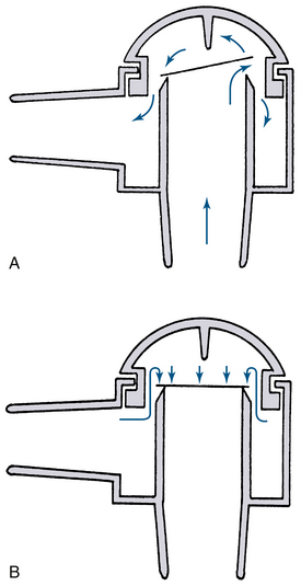
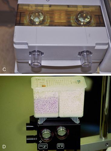
FIGURE 4-4 A, Typical dome valve incorporated into a circle absorber housing. The valve is in the open position with gas flowing. B, Because of backpressure, the plastic disk seats on the knife edge and the valve is closed. C, One-way valves on the Datex-Ohmeda machine (GE Healthcare, Waukesha, WI). D, Datex-Ohmeda ADU absorber block showing unidirectional valves mounted vertically. (Courtesy K. Premmer, MD.)
A nonrebreathing system requires two appropriately placed one-way respiratory valves (Fig. 4-5). Nonrebreathing valves permit the patient to inspire fresh gas from a reservoir and exhale alveolar gas into the room or into a scavenger. Such valves usually consist of a pair of leaflets in the same housing: one opens during inspiration, the other opens during expiration. The early nonrebreathing valve designs, such as the Digby-Leigh or Steven-Slater, required the anesthesiologist to occlude the expiratory valve with a finger if assisted or controlled ventilation was needed (Fig. 4-5, A).9,24 Modern designs that use springs, magnets, or flaps automatically close the expiratory valve when respiration is controlled.39-44 Other designs use the pressure difference across the inspiratory valve to inflate a mushroom-shaped balloon (Frumin) valve (Fig. 4-5, B),11 or to depress a dome-shaped cover on the expiratory (Fink) valve.6 Resistance is negligible in both designs, but the Frumin valve has the marked advantage of collapsing if the inspiratory supply is inadequate, permitting inspiration of room air. The Frumin valve also is lighter and more compact than the others. Some nonrebreathing valves are position sensitive and must be vertically oriented to function properly.45 Those that use flexible rubber leaflets or collapsible rubber tubing to provide the sealing function are not positional. Most nonrebreathing valves connect to masks and/or tracheal tubes, but a valve can be built into a mask.44
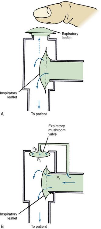
FIGURE 4-5 These nonrebreathing valves incorporate two leaflets that open alternately on inspiration or expiration. A, In the simplest form, the valve functions well during spontaneous ventilation (solid arrows), but an attempt to inflate the patient’s lungs manually blows open both inspiratory and expiratory leaflets (dotted arrow) unless the anesthesiologist simultaneously occludes the expiratory valve with a finger. Several nonrebreathing valves have been designed to overcome the necessity for manual assistance of valve function. B, Whenever gas flow opens the inspiratory leaflet, the pressure at point P1 is greater than at point P2 or PB. This pressure difference inflates the mushroom-shaped expiratory balloon, sealing the expiratory limb. If no gas is supplied to the inspiratory limb, spontaneous effort on the part of the patient lowers both P1 and P2 well below atmospheric pressure (PB) so that the mushroom valve collapses and the patient inspires room air.
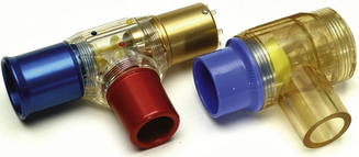
Self-inflating resuscitators for air or air-oxygen mixtures use similar pairs of valves to control gas flow.10,46,47 The Ruben valve has an expiratory bobbin-shaped structure that, when open, occludes the inspiratory limb (Fig. 4-6). Anesthetic vapors and secretions tend to expand this bobbin slightly, causing it to jam.47 Such resuscitator valves should not be used in anesthesia, nor should they be used for transporting patients who are still exhaling anesthetic agents.
Breathing Bags
Breathing bags, also known as reservoir bags or counterlungs, have three principal functions: 1) they serve as a reservoir for anesthetic gases or oxygen, from which the patient can inspire; 2) they provide the means for a visual assessment of the existence and rough estimate of the volume of ventilation; and 3) they serve as a means for manual ventilation. A reservoir function is necessary because anesthesia machines cannot provide the peak inspiratory gas flow needed during normal spontaneous inspiration. Although the respiratory minute volume of an anesthetized adult is rarely more than 12 L/min, the peak inspiratory flow rate may reach 50 L/min, with 20 L/min not uncommon. For example, assume a patient is breathing at a rate of 20 breaths/min with a tidal volume of 500 mL and a minute volume of 10 L/min. If the inspiratory to expiratory ratio (I:E) is 1:2, each breath takes 1 second for inspiration and 2 seconds for exhalation. The tidal volume of 500 mL inspired in 1 second is an average inspiratory flow (volume per unit time) of 500 mL/sec or 30 L/min. This is many times greater than the commonly used fresh gas flows. The peak flow in mid-inspiration may be 30% to 40% higher.
Assessment of the presence and volume of spontaneous ventilation is affected by the fresh gas flow. In low-flow techniques, virtually all the gas inhaled by the patient comes from the reservoir bag, and its excursion thus reflects tidal volume. If the fresh gas inflow rate from the machine exceeds 10 L/min, most of the gas inhaled by the patient comes from the fresh gas supply, and the reservoir bag shows little excursion. In a spontaneously breathing patient with a circuit gas inflow rate of 6 L/min, nearly half the tidal volume comes from the fresh gas inflow, halving the apparent tidal volume as indicated by movement of the bag.
Reservoir bags for anesthesia machines usually are ellipsoid so they can be easily grasped with one hand. They are made of nonslippery plastic or latex in sizes from 0.5 to 6 L. To improve grip, some have an hourglass shape or a textured surface; nonlatex bags are available for use with patients who have a latex sensitivity. The optimally sized bag can hold a volume that exceeds the patient’s inspiratory capacity; that is, a spontaneous deep breath should not empty the bag. For most adults, a 3-L bag meets these requirements and is easy to grasp. Bags with a nipple at the bottom for use as an alternate pop-off site are available but are rarely used.
In circle systems, the breathing bag usually is mounted at or near the carbon dioxide absorbent canister via a T-shaped fitting, usually near the pop-off valve. The bag also may be placed at the end of a length of corrugated tubing leading from the T-connector to provide some freedom of movement for the anesthesiologist. The pressure-volume characteristics of overinflated bags become important if the pop-off valve is accidentally left in the closed position and gas inflow continues (Fig. 4-7). Rubber bags become pressure limiting with maximum pressures of 40 to 50 cm H2O, although prestretching may favorably lower the maximum distending pressure.48-50 Disposable bags may reach twice the pressure of rubber bags and then rupture abruptly.
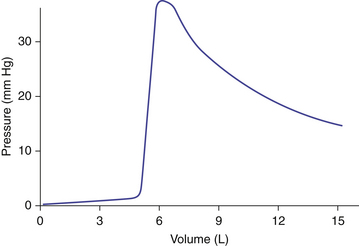
FIGURE 4-7 As an anesthesia reservoir bag is filled from its evacuated volume to its nominal volume, the pressure increases little; as the rubber is slightly stretched, however, a small increase in volume rapidly raises the pressure to some maximum, depending on the shape and wall thickness of the bag. Further increase in the bag’s volume causes a decrease in pressure. The falling pressure with rising volume follows Laplace’s law: P = 2T/r, where P is pressure, the constant T is a function of the bag’s thickness and material, and r is the radius.
Gas Inflow and Pop-off Valves
Gases are delivered from the anesthesia machine common gas outlet to the circuit via thick-walled tubing connected to a nipple incorporated into the circuit. In circle systems this gas inflow nipple is incorporated with the inspiratory unidirectional valve or the carbon dioxide–absorbent canister housing. The preferred fresh gas inflow site is between the carbon dioxide absorber and the inspiratory valve. The location for other circuits depends on whether breathing is spontaneous, assisted, or controlled because the type of breathing influences the efficiency of carbon dioxide elimination.
Pop-off valves—also known as overflow, outflow, relief, spill, and adjustable pressure-limiting (APL) valves—permit gas to leave the circuit, matching the excess to the inflow of fresh gas. The efficiency of an APL valve is related in part to the placement of the fresh gas inflow. There are many different designs, but most are constructed like a dome valve loaded by a spring and screw cap (Fig. 4-8). The valve should open at a pressure of less than 1 cm H2O. As the screw cap is tightened down, more and more gas pressure in the circuit is required to open it, permitting PEEP during spontaneous ventilation or pressure-limited controlled respiration. The number of clockwise turns from fully open to fully closed should be one or two: fewer turns make it difficult to set a desired circuit pressure accurately, whereas more make it tedious to use. The exhaust from any of the commonly used pop-off valves can be collected by scavenging system transfer tubing connected at this point.51
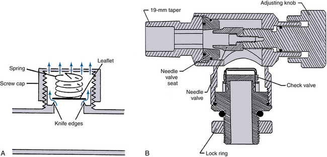
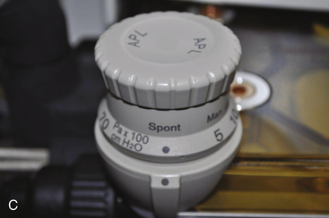
FIGURE 4-8 Adjustable pressure-limiting (APL) or “pop-off” valves. A, Spring-loaded design. When the cap is fully tightened down, the spring is compressed enough to prevent the valve leaflet from lifting at any airway pressure. When the top is loosened and the spring is not compressed, the valve opens at a pressure equal to the weight of the leaflet divided by its area, usually <1 cm H2O. B, The Dräger Medical (Telford, PA) APL valve design is an adjustable needle valve, the opening of which determines gas flow into the scavenger system. The check valve prevents reverse flow of gas from the scavenger into the patient circuit. C, A pop-off valve from a Dräger Apollo anesthesia workstation. This APL valve is similar to that in A and has approximate calibrations. (A and B, Courtesy Dräger Medical, Telford, PA. C, Courtesy K. Premmer, MD.)
The Datex-Ohmeda GMS absorber uses an APL valve similar in design to that shown in Figure 4-8, which basically is a spring-loaded disk. When the spring is fully extended, it exerts a pressure of approximately 1 cm H2O on the disk to hold the valve closed. This is necessary because the waste gas scavenging interface is connected downstream of the APL valve and transfer tubing. If an active scavenging system is used—that is, if suction is applied to the interface—the negative pressure could potentially be applied to the patient circuit (see Chapter 5). To prevent this, the Ohmeda scavenger interface uses a negative-pressure relief (“pop-in”) valve that opens at a pressure of −0.25 cm H2O to allow room air to enter the interface. Thus the greatest negative pressure needed to open the APL valve (−0.25 cm) is less than the least spring tension needed to keep the valve closed (~1 cm H2O). This arrangement, with the use of an active scavenging system, protects against application of excess negative pressure to the breathing circuit. In the fully closed position, the maximum spring pressure applied to the Datex-Ohmeda APL valve disk is 75 cm H2O. Thus, in the manual/bag mode, the circuit pressure in an Datex-Ohmeda breathing system is limited to 75 cm H2O. Note that in the ventilator mode, the circuit pressure is limited by high pressure-limit settings on the Datex-Ohmeda ventilator (up to 100 cm H2O with the Datex-Ohmeda 7800 and 7900 ventilators; see Chapter 6).
In Dräger Medical (Telford, PA) anesthesia delivery systems, the design of the APL valve differs from those described above (see Fig. 4-8, B). This design uses a needle valve instead of a spring-loaded disk, and adjusting the knob varies the size of the opening between the needle valve and its seat, which in turn adjusts the amount of gas permitted to flow to the scavenger system. A check valve prevents gas from the scavenging system from entering the breathing system. With this design, the needle valve can be totally closed; it therefore does not function as a true pressure limiter.
Special types of pop-off valves permit spontaneous or assisted respiration without tedious adjustment.40,52-54 The simplest is the Steen valve (Fig. 4-9), which essentially is two knife-edge valves of the dome type, one inverted over the other, that share a common disk.24 A relatively slow flow of gas during the latter part of exhalation, up to 10 L/min, lifts the valve disk at one side only so that the exhaled gas escapes around the disk. An abrupt increase in pressure lifts the valve vertically, seals it against the upper knife edge, and closes the circuit so that no gas is lost. The Georgia valve adds a light spring loading to the same design, which increases the range of gas flows it can exhaust; this is necessary for use with mechanical ventilators.55 Most current anesthesia ventilators have such an automatic pop-off valve built in so that gas is exhausted only at end exhalation (see also Chapter 6).
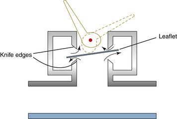
FIGURE 4-9 The Steen valve permits gas to exit from a circuit under the slight pressure that occurs during exhalation. However, a sudden rise in pressure, such as occurs during an assisted or controlled inhalation, seals the leaflet against the upper circular knife edge. A lever-operated eccentric cam defeats this effect if desired and turns the valve into an ordinary pop-off valve that is not spring loaded.
Carbon Dioxide Absorption
In partial rebreathing and nonrebreathing systems, carbon dioxide is vented to room air. When a closed system is used, however, the exhaled carbon dioxide must be otherwise removed. Carbon dioxide in the presence of water is hydrated to form carbonic acid. When carbonic acid reacts with a metal hydroxide, the reaction is one of neutralization that results in the formation of water and a metal bicarbonate or carbonate and the generation of heat. This reaction is used in anesthesia for carbon dioxide absorption.56 In the reactions shown below, only the molecular forms of the reactants are written. The reactions actually proceed by initial ionization in the thin film of water at the surfaces of the absorbent. In soda lime:


In barium hydroxide lime—or Baralyme, which is no longer being produced (see Chapter 30)—Ba(OH)2 replaces the NaOH and KOH in equations 4-2, 4-3, and 4-4, with BaCO3 the product.
Wet soda lime is composed of calcium hydroxide (~80%), sodium hydroxide and potassium hydroxide (~5%), water (~15%), and small amounts of inert substances such as silica and clay for hardness. The potassium hydroxide and sodium hydroxide function somewhat like a catalyst to speed the initial reaction, forming sodium and potassium carbonates. The sodium and potassium carbonates react over the course of minutes with the calcium hydroxide to form calcium carbonate and water, regenerating sodium and potassium hydroxides. Soda lime is exhausted when all the hydroxides have become carbonates. Soda lime can absorb 19% of its weight in carbon dioxide5; thus 100 g of soda lime can absorb approximately 26 L of carbon dioxide.
A novel carbon dioxide absorbent was created in 1999. Calcium hydroxide lime (Amsorb) is composed of calcium hydroxide (70%); a compatible humectant, calcium chloride (0.7%); and two setting agents, calcium sulfate (0.7%) and polyvinylpyrrolidine (0.7%), to improve hardness and porosity; and water (14.5%).57 By adding calcium chloride as a humectant, the calcium hydroxide remains damp and eliminates the need for sodium or potassium hydroxide. With removal of the strong alkali, calcium hydroxide lime has potential benefits that include decreased formation of compound A with sevoflurane use, minimal formation of carbon monoxide when exposed to desflurane or isoflurane, and minimal destruction of inhaled agents.58
Indicator Dyes
Organic dyes are added to soda lime and barium hydroxide lime to provide a visual indication of its state. As carbonate is formed from the hydroxide, the pH becomes less alkaline and the granules change color: ethyl violet changes from white to blue violet with exhaustion, ethyl orange from orange to yellow, and cresyl yellow from red to yellow. Ethyl violet is the dye most commonly used because the color change is vivid and of high contrast at a pH intermediate between NaOH and CaCO3. It can be bleached by intense light, but in the usual OR setting this is not a problem. A slight fading of color can be seen in the zone of active absorption when use stops. This so-called regeneration occurs where the lime is nearly exhausted of calcium hydroxide but has all alkaline hydroxides neutralized.
The color changes only because of the regeneration of a small amount of sodium and potassium hydroxide. At the next use, the expended nature of the soda lime rapidly becomes evident. There is no true regeneration of activity, and the color change of indicator lime is not to be relied on. The anesthesiologist must know what color change is expected of the absorbent being used, allow for the effects of regeneration, be cognizant of the effects of preferential gas flow at the surface between the smooth plastic canister and the irregular granules (channeling), and understand the effects of the fresh gas flows chosen based on how long a given charge of soda lime can be expected to last. No indicator or rules offer absolute predictions, but the use of capnometry to detect increasing inspired carbon dioxide remains the gold standard for assessing adequate carbon dioxide removal.
Mesh Size and Channeling
Soda lime is precisely manufactured to maximize its absorptive qualities and to minimize resistance to gas flow.5 The granules are sized 4 to 8 mesh (i.e., they will pass through a strainer having 4 to 8 wires per inch) and have a rough, irregular surface that maximizes the surface/volume ratio that facilitates the rapid diffusion of carbon dioxide through the pores to the voids within the granules.56,59-62 Approximately half the volume of a packed canister is gas. The gas volume of the voids is inversely proportional to the water content of the granules and is 1 to 2 times that of the volume between granules. Soda lime is supplied either in quart cartons that fill a canister, disposable canisters, or bulk containers ranging from 5 pounds to 5 gallons. The volume between granules can be reduced by overzealous packing at the risk of creating fine particles and dust that are irritating. Channeling, or flow moving preferentially along the sides of the canister and within the absorbent itself, was a problem with to-and-fro canisters that were often horizontal and improperly packed. This problem can be minimized by the use of baffles, placement so that gas flow is vertical, permanent mounting to avoid frequent canister movement, use of prepackaged cylinders, and avoidance of overly tight packing. Modern carbon dioxide–absorbent canisters (Fig. 4-10) follow the design of the Roswell Park absorber with double chambers to promote efficient use, circular baffles to minimize channeling, and mixing space at the top and bottom.19,56 Although most have clear plastic walls, some are tinged blue for the purpose of enhancing the appearance of color change in the indicator dye.
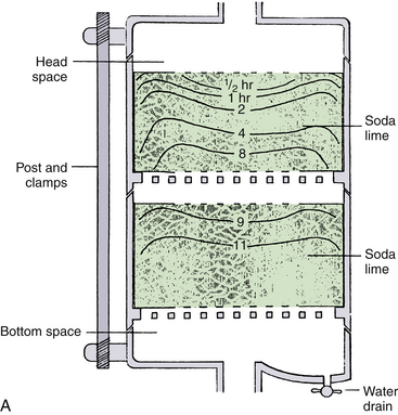
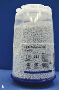
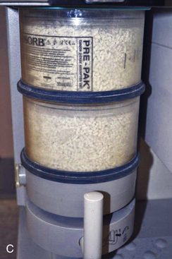
FIGURE 4-10 A, Schematic of modern carbon dioxide absorbent canister. Originated by Elam and Brown, these transparent twin-chambered canisters are now supplied by all producers. Permanently mounted with a vertical gas-flow axis, they eliminate dusting, channeling, and packing problems. Used as intended, changing the exhausted canister only when the second half is exhausted, they use the absorptive capacity of soda lime fully, as shown by the lines illustrating patterns of exhaustion. Drop-in, prepacked containers add convenience. The nearly standard shape is 8 cm high and 15 cm in diameter. Because water condensate may collect at the bottom and form a caustic lye solution with the dust, a drain valve is an important component. Convenience of opening, closing, and sealing varies with design, but most now have a single-action clamp mechanism. The casting for the top and bottom should be resistant to alkaline corrosion and may incorporate other components of the breathing circuit (e.g., bag mount, inflow site, and valve housings. B, Prefilled single-chamber canister. C, Twin canister on Datex-Ohmeda Aestiva machine. (GE Healthcare, Waukesha, WI). (B and C, Courtesy K. Premmer, MD.)
Other Reactions with Absorbents
Sevoflurane did not gain U.S. Food and Drug Administration (FDA) approval for use until 1995 despite its use in Japan and elsewhere since the 1970s. When sevoflurane was first described, early testing revealed the production of fluoromethyl-2,2-difluoro-1-(trifluoromethyl) vinyl ether, better known as compound A, when sevoflurane is exposed to various alkalis, including soda lime.63 This reaction occurs when hydrogen fluoride is eliminated from the isopropyl moiety of sevoflurane. Concern arose over evidence that compound A is nephrotoxic—and, at higher concentrations, lethal—in rats.64-66 Although studies of the nephrotoxicity of compound A in humans have had conflicting results,67-69 sevoflurane has been administered with apparent safety for several years.68 What is clear is that certain factors related to the breathing system can contribute to the production of compound A during anesthesia with sevoflurane. These include increasing inspired sevoflurane concentration, increasing absorbent temperature, decreasing absorbent water content (desiccation), and a decreasing fresh gas flow rate.70,71 Hypotheses to explain the effect of low flows on compound A production include increased contact of exhaled gas with carbon dioxide absorbent, increased rebreathing of compound A, and increased absorbent temperature. Current sevoflurane labeling indicates that whereas a fresh gas flow from 1 to 2 L/min may be used safely for fewer than 2 minimum alveolar concentration (MAC) hours, flows less than 2 L/min should not be used for more than 2 MAC hours, and flows below 1 L/min are not recommended for any duration with this agent. The choice of absorbent, whether barium hydroxide lime or soda lime, does not seem to significantly influence production of compound A (Fig. 4-11).70,72
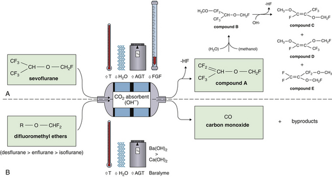
FIGURE 4-11 The degradation of volatile anesthetics by carbon dioxide absorbents. A, Production of compound A from sevoflurane is promoted by warmer, drier absorbent and by higher concentrations of agent (AGT) and lower fresh gas flows (FGF). In the presence of water, sevoflurane produces methanol, which promotes the breakdown of compound A into compound B and other low-toxicity products C, D, and E. B, The phenomenon of carbon monoxide (CO) production from the difluoromethyl ethers (desflurane, enflurane, and isoflurane) is often the result of prolonged high gas flows, which dry out the absorbent. Higher temperatures (T) and agent concentrations increase CO production in this setting, and the use of barium hydroxide lime (Baralyme) results in more CO production than the use of soda lime.
Desiccation of carbon dioxide absorbents is known to be related to another potential hazard, that of carbon monoxide production. The notion that carbon monoxide could be found in detectable amounts in anesthesia breathing circuits containing soda lime was first reported with the use of trichlorethylene and during closed-circuit anesthesia secondary to endogenous production.73 More recently, it has been recognized that difluoromethyl ethers in common use today, including desflurane and isoflurane, can liberate carbon monoxide during destruction of these agents by carbon dioxide absorbents.74 Difluoromethyl ethers are fluorinated volatile anesthetics that contain an –O–CHF2 moiety. Early case reports of unexplained carboxyhemoglobinemia during enflurane anesthesia pointed to an association with “first case on Monday morning” anesthetics75 or with older absorbents.76 This has been explained by invitro studies that revealed a marked association between dryness of the absorbent and production of carbon monoxide.74 It is theorized that high oxygen flows over the absorbent canister during the weekend, or after prolonged absorbent use, desiccate the absorbent. The type of anesthetic is important, with the order of carbon monoxide production being desflurane, which produces the most, followed by enflurane then isoflurane. Sevoflurane and halothane lack an –O–CHF2 moiety and do not appreciably produce carbon monoxide in the presence of carbon dioxide absorbents. Barium hydroxide lime seems to cause greater carbon monoxide liberation than does soda lime, but both absorbents produce more carbon monoxide with increasing temperatures and with increasing concentrations of anesthetic.74 Recognition of the presence of carbon monoxide in an anesthesia breathing circuit in which desflurane or isoflurane is being used may be facilitated by the use of a multiwavelength pulse oximeter (pulse CO-oximeter; see Chapter 11) that can continuously measure carboxyhemoglobin. Such devices are available and used in emergency departments but are not yet widely used in the operating room.77-78 It is recommended that absorbent that is known or suspected to be desiccated not be used, especially with desflurane, isoflurane, or enflurane. The FDA recommends replacement of any absorbent suspected of contributing to the presence of carbon monoxide in the breathing circuit, although some investigators have suggested rehydration of existing absorbent as a practical and more cost-effective alternative.79
Alternatives to soda lime are available. For example, lithium hydroxide offers a little more carbon dioxide absorption capacity per unit of volume but more than three times per unit of weight; it is therefore used in submarines. Barium hydroxide lime contains 20% Ba(OH)2 and little alkali. Its dust is slightly less alkaline when dissolved in water, and it is a suitable alternative to soda lime.80 The end products are barium carbonate and calcium carbonate. It is initially pink but turns blue-gray with exhaustion because of two indicator dyes, Mimosa Z and ethyl violet. Barium hydroxide is as efficient as soda lime per unit of volume, but because of its density, it is half as efficient per unit of mass.
Methods of carbon dioxide removal other than chemical reaction with metal hydroxides have also been investigated. Much of the research in this area has originated from aviation, space, and submarine technology. One method of particular interest is a molecular sieve that uses synthetic zeolites, crystalline hydrated aluminosilicate materials, arranged in a three-dimensional tetrahedral framework that contains entry pore sites and cavities.81 Gases that enter the sieve separate on the basis of size and polarity. Carbon dioxide is a polar molecule and is retained in certain zeolites by the action of Van der Waal forces. Because chemical bonding does not take place, the process can be reversed by slight changes in pressure and temperature, thus allowing regeneration of saturated zeolite. This technology has already been used extensively in industry for petroleum refining, water purification, and drying of gases and liquids. It has also been used for aviation and medical purposes in oxygen generators.82,83 Advantages suggested for the use of molecular sieves in anesthesia breathing systems include lack of compound A in the presence of sevoflurane, avoidance of carbon monoxide production, removal of nitrogen dioxide in circuits that deliver nitric oxide, and cost savings as a regenerative process.84,85
Mixing Devices
Resistance to gas flow in a modern circle system is less than 1 cm H2O/L/min of gas flow, one half of a person’s normal airway resistance to gas flow.35,36 Patients, including infants and children, may safely breathe spontaneously from a circle system for prolonged periods. However, before circuit designs permitted such low resistances, attempts were made to decrease resistance to breathing by providing a continuous flow of gas around the circle, thereby causing the inspiratory and expiratory valves to float open rather than open and close with each breath. Both pumps and Venturi devices driven by fresh gas flow were designed, the most prominent of which was the Revell circulator.86,87 Although these devices can decrease dead space and resistance in the apparatus, the potential benefit is slight; in some circumstances these devices can backfire, actually increasing the work of breathing. If the low resistance of modern equipment is still a concern, it can be eliminated by controlled ventilation. Ways to reduce the mean airway pressure during controlled ventilation have been suggested but are not commonly used.88
Mixing of the expirate is required to measure carbon dioxide production and physiologic dead space. Standard physiologic testing usually collects all the expired gas for several minutes to mix and measure the mixed expired gas concentrations needed in these calculations (see also Chapter 8). Simply averaging a continuous capnogram will not do; this yields a time-weighted average instead of the required volume-weighted average. To understand the difference, consider what happens toward the end of a respiratory cycle. While the carbon dioxide is increasing slightly, the flow is rapidly decreasing and may become zero at the end-expiratory pause. Carbon dioxide excretion should be the integral of concentration with respect to flow; when flow falls to zero, so does carbon dioxide excretion, but the increased end-tidal value continues to increase the time-weighted integral of the capnogram. Special volume mixing devices can be used, but suitable sites for such measurements may include the breathing bag, the ventilator bellows, or the expiratory port of the ventilator pressure relief valve at its connection with the scavenging system.
Bacterial Filters
There is little doubt that anesthesia breathing systems are susceptible to contamination from the patient and the environment.89 What is less clear is what risk this poses to subsequent patients and whether bacterial filters are necessary. Despite a recent resurgence of interest, in part related to a hepatitis C outbreak among patients sharing a common breathing system in an OR in New South Wales in 1993,90 an international consensus on the use of bacterial filters in anesthesia systems remains elusive. However, the American Society of Anesthesiologists concludes in its recommendations for infection control that a “bacterial filter with an efficiency rating of more than 95% for particle sizes of 0.3 µm should be routinely placed in the anesthesia circuit, where it will protect the machine from contamination with airborne infectious diseases.”91
Multiple invitro studies of various filters have demonstrated bacterial filtration efficiencies (BFEs) in the range of greater than 99.9% and viral filtration efficiencies (VFEs) of 96.43% to 99.84%.89 These efficiencies are achieved in the myriad commercial filters now available by the use of one of two fiber arrangements. The first consists of a small-pore compact matrix with a high airflow resistance offset by pleating to create a larger surface area. The second is a less dense, larger pore size arrangement that has less resistance to accommodate a smaller surface area. Some filters possess a permanent electrical polarity designed to enhance the Van der Waal forces that hold organisms within the matrix. Some are also considerably hydrophobic, which prevents water penetration and subsequent increased resistance and loss of efficiency. A few have combined roles as filters and heat and moisture exchangers (HMEs). These filters generally are placed at the Y-piece and serve as both an inspiratory and expiratory barrier, whereas standard filters usually are placed on the expiratory limb.
Considering the favorable evidence regarding filtration efficiency, the question of whether to use filters might be simpler if they were free of problems. Complications reported with the use of breathing system filters are in general related to either obstruction or leakage. Obstruction has been described when filters become saturated with circuit humidity as a result of sputum,92,93 edema fluid,94 nebulized aerosols,95 or malpositioning of the filter.96 In one case, a leak in the housing of a gasline filter resulted in patient hypoxia.97 Another consideration is cost; at least one author advocates the use of disposable or autoclavable circuits, carbon dioxide absorbers, and ventilator bellows—all components in contact with the patient’s breathing circuit—based in part on cost advantage because filters become unnecessary.98 Also of concern is the lesser efficiency of bacterial filters with regard to viruses. After discussing the efficiency of bacterial filters and the low likelihood of cross-contamination during their use, Hogarth,89 in his excellent review of the subject, concludes that “the use of filters within the breathing system adds a known risk to the patient, against which must be balanced the unknown risk of viral contamination and cross-infection by agents both known and unknown.”
In addition to bacterial filters, the breathing circuit also may incorporate a spirometer to measure ventilation, a humidifier to provide warmth and moisture, sampling sites for gas analysis, and scavenging devices to control atmospheric contamination by waste gases in the OR. These subjects are discussed in Chapters 5, 7, 8, 9, and 20.
Analysis of Specific Circuits
The basic components of a circle breathing system are an inspiratory and expiratory limb, each with a unidirectional valve, and a reservoir bag or counterlung that moves reciprocally with the patient’s lungs. The system may be divided into quadrants (Fig. 4-12). The patient and counterlung, but not the absorber, separate the inspiratory and expiratory limbs of the system; the valves separate the patient from the bag side of the system. The position of the valves within the limbs is not necessarily fixed; they may be anywhere between the patient and the bag with little practical difference in function. They usually are incorporated with the bag mount, pop-off valve, and absorber for manufacturing ease and durability. Even if the valves are moved to other locations, it is convenient to think of four quadrants when analyzing circle systems.
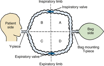
FIGURE 4-12 The four quadrants of a basic circle system. Two corrugated breathing tubes connect the patient and the counterlung (a bag or a ventilator bellows). One-way valves are located in the inspiratory limb and in the expiratory limb. The circle is therefore bisected twice, dividing it into four quadrants: A, B, C, and D. To make a practical circuit for anesthesia, three more essential components must be added: a fresh gas inflow site, a pop-off valve, and a carbon dioxide absorber.
For practical anesthesia, it is necessary to add three other components: a carbon dioxide absorber, a fresh gas inflow site, and a pop-off valve for venting excess gas. Each of the three may be placed in any of the four quadrants. There are hundreds of different ways to place three components in four quadrants, but only a few are used.99 Different manufacturers have used different arrangements, and older designs allowed the user to change the configuration with slight change in function. The optimal configurations for spontaneous and controlled ventilation are different,18 and most current designs are optimal for controlled ventilation.
This analysis emphasizes a frequently overlooked or misunderstood point: The bag, not the absorber, is on the opposite side of the circle from the patient. Most schematics and diagrams of breathing circuits perpetuate this misconception by showing symmetrical circuit limbs on either side of the absorber. The position of the bag is at neither the inspiratory limb nor the expiratory limb; rather it separates the two.37
Placement of the Carbon Dioxide Absorber, Fresh Gas Inflow, and Pop-off Valve
The carbon dioxide absorber may be placed in any of the four quadrants but is almost invariably placed in the inspiratory limb on the bag side so that apparatus resistance to inspiration may be overcome with assisted or controlled ventilation (Fig. 4-13). Placement on the expiratory side (Foregger circles) adds a mild degree of expiratory resistance that, like PEEP, may be beneficial for oxygen exchange but increases the risk of barotrauma. A bypass valve to permit carbon dioxide to build up was considered desirable by a majority of anesthesiologists but not by those who build the apparatus.100 The carbon dioxide absorber is absolutely necessary in a low fresh gas flow technique because no other method is available to remove carbon dioxide; that is, it is removable neither by dilution nor exclusion from reinspiration. As fresh gas flow is increased above gas uptake rates, the other methods become increasingly effective. This is noted by the anesthesiologist as longer intervals before the indicator in the absorbent suggest that it be replaced. At a 5 L/min fresh gas flow, the absorbent lasts more than twice as long as at 500 mL/min. This is not cost effective because the extra anesthetic gases and vapors cost more than the absorbent saved. In addition to saving on agents, the absorbent has two other beneficial effects: both expired humidity and heat are partially conserved, and both are optimized as flow decreases.101,102 The risks of absorbent (e.g., soda lime) include airway reaction to inspired alkaline dust, which can be minimized by good design and technique; alkaline “burns” from condensed water and/or dust spilled from the canister housing; and a breathing circuit with more connections and pieces, which provides more opportunity for user error.
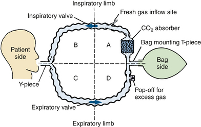
FIGURE 4-13 Placement of the carbon dioxide absorber, fresh gas inflow, and pop-off valve. The typical site for the absorber is in the inspiratory limb on the bag side, that is, in quadrant A. The inspiratory valve typically is mechanically attached to the canister but is shown here as it was in Figure 4-12 for ease of analysis. Fresh gas inflow usually is on the bag side in the inspiratory limb (quadrant A), downstream from the carbon dioxide absorber. The pop-off valve typically is downstream from the expiratory valve, near the bag. It is shown here in quadrant D but could be in A, before the carbon dioxide absorber.
Although the inflow site for fresh gas may be physically placed in any of the four quadrants, efficiency and manufacturing convenience also are factors in placement.18,103 The inflow site usually is incorporated with the other components; that is, the absorber, bag mount, and valves. If the inflow site is located on the patient side of the inspiratory valve (quadrant B, Fig. 4-13), gas flows continuously around the circle throughout the respiratory cycle. Thus spirometry in the expiratory limb is inaccurate unless total gas flow is shut off.104 If inflow is located on the patient side of the expiratory valve (quadrant C, Fig. 4-13), any carbon dioxide–containing alveolar gas between the Y-piece and the patient is washed into the patient’s lungs during inspiration at the rate of the fresh gas flow. This may be negligible during closed-system anesthesia, but it can produce rebreathing of up to half of the previously exhaled alveolar gas at total flows of 10 L/min. Placement in quadrant D is simply inefficient because some fresh gas will be lost to the pop-off valve in most circles.
Recommended placement for the fresh gas inflow is on the bag side of the inspiratory limb between the inspiratory valve and absorber (quadrant A, Fig. 4-13). If the absorber housing has appreciable head space, as is common, this inflow site stores the continuously delivered fresh gas during exhalation. Gas flows down the inspiratory limb only during inspiration. During exhalation, fresh gas flows backward toward the absorber, bag, and pop-off valve. Thus fresh gas provides most of or all the respired gas with high-flow techniques, or it enriches the oxygen and anesthetic-depleted expiratory gas with low-flow techniques.
The pop-off valve may be placed anywhere in the circle, but some locations are more rational than others. Locating the valve in the inspiratory limb (quadrants A and B, Fig. 4-13) tends to vent fresh anesthetic and carbon dioxide–free gas. Furthermore, locations in the inspiratory limb on the patient side (quadrant B) permit some carbon dioxide–containing exhaled gas to enter the inspiratory limb during the end of a spontaneous breath. This rebreathing is clearly undesirable. It is mechanically convenient to place the pop-off valve between the expiratory valve and the bag mount, or opposite the bag mount, before the absorber (i.e., in quadrants D or A, but close to the bag mount). Incorporating the pop-off valve into a one-piece absorber/bag mount/expiratory valve/pop-off valve assembly provides convenience and durability.
There is at least theoretic value to locating the pop-off valve on the patient side at the Y or next to it (quadrant C, Fig. 4-13). During spontaneous inspiration, the pressure at this site is below atmospheric pressure and the pop-off valve is closed. During exhalation, the pressure is just slightly above atmospheric pressure, and gas flows to the reservoir bag until it is distended to its nominal volume. Then the pressure in the entire circuit increases as fresh gas inflow and exhalation from the patient continue, opening the pop-off valve. The gas vented is primarily carbon dioxide–rich, oxygen-depleted, and anesthetic-depleted end-tidal gas. However, the situation is reversed during assisted or controlled ventilation. During inspiration, the pressure in the circuit at the Y-piece is positive with respect to atmospheric pressure. A pop-off valve located at the Y-piece would dump fresh gas, and one near the bag would dump a mixture of dead space gas and end-tidal gas. Two pop-off valves on the same circuit double the risk of hypoventilation when ventilation is changed to manual because the anesthesiologist may fail to close both valves. For this reason, pop-off valves at the Y-piece are no longer used.
Flow and Concentration
The gas mixture inspired by a patient breathing from a circle system is determined by the fresh gas inflow, the configuration of the circle, the respiratory pattern, and the uptake by the patient of oxygen and anesthetics. At fresh gas inflow rates that exceed minute ventilation, the circle behaves similar to a nonrebreathing system. The concentration of inspired gas closely approaches that being delivered from the gas flowmeters on the machine. As flow is progressively decreased, a disparity between fresh gas inflow and actual inspired concentration of anesthetics increases.
In a closed system, in which inflow matches loss from the system, the composition of reinspired gas is not predictable from the inflow concentration of gases.105 Inspired and exhaled gases differ because of uptake of oxygen and anesthetic and excretion of carbon dioxide. Oxygen concentration in mixed exhaled gas usually is 4% or 5% lower than that in inspired gas. Although oxygen uptake remains relatively constant during anesthesia (approximately 250 mL/min standard temperature and pressure dry [STPD]) in the average adult, provided that body temperature does not change appreciably, anesthetic uptake varies; it is greatest at the start of anesthesia and decreases with time. If oxygen concentration is maintained constant during closed-system anesthesia, the flowmeter values reflect oxygen consumption and anesthetic uptake by the patient rather than inspired concentrations. When nitrous oxide is used in closed-system anesthesia, the oxygen tension or concentration in the circle must be continuously monitored because nitrous oxide uptake declines but oxygen uptake does not. The inspired gas mixture may become hypoxic if the nitrous oxide inflow is not gradually decreased. Whether it is necessary to measure the concentration of potent volatile anesthetics during closed-system anesthesia remains controversial. Some believe that it is necessary, and others prefer to monitor anesthetic depth and patient responses clinically (see also Chapter 26).
Semiclosed Systems: Mapleson Classification
Mapleson configurations of Magill circuits are characterized by a reservoir that can be filled by fresh gas, exhaled gas, or both. They may or may not have a pop-off valve, but if one is present it does not prevent rebreathing. Carbon dioxide, eliminated by both dilution with fresh gas and by efficient arrangement of the circuit components, is critically affected by total fresh gas flow and the pattern of respiration. The pattern of respiration includes the respiratory rate, tidal volume, dead space, I:E ratios, and inspiratory and expiratory flow patterns. The earliest semiclosed systems consisted of a bag attached to a mask by an elbow or a length of breathing tubing if it was desirable to move the large bag away from the face. The inlet for fresh gas was through a nipple on the elbow or through the tail of the bag, and a pop-off valve was placed either at the bag’s tail or at the elbow. The bag ideally contained a volume approximating the patient’s inspiratory capacity, about 3 L in an adult, to permit spontaneous deep breaths without the feeling of suffocation. Gas flows totaling 1 to 2 times the minute volume were used.8,101 Mapleson organized the various configurations into five typical models and later added a sixth (Fig. 4-14).7,26 Each of these breathing systems may be thought of as part of the continuum shown in Table 4-2.
TABLE 4-2
Spectrum of Carbon Dioxide Elimination
| Maximum Carbon Dioxide Elimination | To | Maximum Carbon Dioxide Retention |
| No mixing of fresh and alveolar gas occurs. | Complete mixing of fresh and alveolar gas occurs. | No missing of fresh and alveolar gas occurs. |
| Fresh gas goes to the patient. | The mixture is inhaled. | Alveolar gas is rebreathed. |
| Alveolar gas goes to the pop-off valve. | Fresh gas and mixed gas are “popped off” simultaneously. | Fresh gas goes to the pop-off valve. |
| DESIRABLE | ACCEPTABLE | UNDESIRABLE |
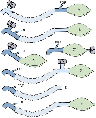
FIGURE 4-14 Mapleson classification of breathing systems. Note that the semiclosed systems (top four) contain most of the components of a circle system: tubing, connectors, bag, fresh gas inflow (FGF), and pop-off site. They lack carbon dioxide absorbers because carbon dioxide is lowered by the addition of fresh gas and elimination of carbon dioxide–rich gas preferentially through the pop-off valve. They also lack separate inspiratory and expiratory limbs; one tubing serves both purposes. The Mapleson A system (Magill attachment) is optimal for spontaneous respiration. The Mapleson C system is a simple bag and mask. Moving the pop-off to the bag tail is a major improvement (Cʹ), because this permits more mixing of fresh and exhaled gas than the Mapleson C (this modification, not one of Mapleson’s, has been added by the author). The B circuit is wasteful of fresh gas in both spontaneous and controlled respiration. The D circuit is similar to the A except that it exchanges the inflow and pop-off sites. A is optimal for spontaneous breathing, and D is best for controlled breathing. The Mapleson E system is essentially an Ayre’s T-piece with an added reservoir. If the reservoir is short, it is an open, not a semiclosed, system. This system is simple but lacks the convenience of a bag for ventilatory assistance or control. A bag can be added to it (F, or Jackson-Rees modification), which may or may not possess an adjustable pop-off valve to help assist or control ventilation. All these circuits share a common advantage. Vigorous hyperventilation cannot reduce the patient’s carbon dioxide tension much below normal if FGF is kept between one and two times the patient’s normal respiratory minute volume.
In Table 4-2, the far right situation represents complete rebreathing and is of use only in the study of respiratory control. The original Mapleson B and C configurations lie midway on the continuum and are judged to have no particular merit, except perhaps for brief procedures or to transport patients while supplemental oxygen is administered and breathing is augmented.
None of the Mapleson systems meets the requirements on the far left of Table 4-2, but with optimal configuration and high fresh gas flow, they may approach the function of an open system. Efficiency of the systems in this context can be translated as the lowest fresh gas flow that will ensure normal removal of carbon dioxide, thereby minimizing rebreathing. There is normally a partial pressure difference for carbon dioxide such that alveolar CO2 (PACO2) is greater than mixed expired CO2 (PECO2), which is greater than inspired CO2 (PICO2).


The most efficient configurations place the pop-off valve where the highest concentration of carbon dioxide is found during the phase of breathing in which the circuit pressure is above atmospheric pressure. This occurs at end expiration during spontaneous breathing and during inspiration with manually assisted or controlled breathing.
A great deal of attention has been devoted to determining the lowest gas flow that can be safely used in clinical anesthesia. A variety of claims have been made for the various circuits and for proprietary modifications of the circuits, such as Bain, Lack, Humphrey ADE, and Mera F circuits. Unfortunately much of the published work has one or more of the following flaws:
1. Theoretical analyses embody unrealistic assumptions about mixing and breathing patterns, especially the I:E ratio and expiratory flow.
2. Model studies embody nonphysiologic states, particularly lack of responsiveness to carbon dioxide and simplified flow patterns.
3. Studies were done in awake volunteers, whose metabolic rates and physiologic responses differ from those of anesthetized patients.
4. Imprecise endpoints were used, such as rebreathing of carbon dioxide identified by capnography rather than by an increase in alveolar or arterial carbon dioxide concentration.
However, consensus has been reached in one regard: systems classified as Mapleson A (Magill attachment, Lack, and Humphrey A) are most efficient for spontaneous, unassisted ventilation, and those classified as Mapleson D, E, or F (Jackson-Rees, Bain, Humphrey DE) are most efficient for assisted or controlled ventilation.
A general criticism of the published analyses of breathing circuits is a failure to distinguish between the quantity of reinspired carbon dioxide and minimum inspired carbon dioxide tension. The most common tool, a capnograph, displays a signal of airway concentration as a function of time. Thus, if airway carbon dioxide falls slowly with inspiration, just reaching zero near end inspiration, it is interpreted as no rebreathing, even though a significant amount of carbon dioxide has been reinspired. Conversely, if airway carbon dioxide falls to a low but nonzero concentration for all of inspiration, carbon dioxide excretion may be adequate despite perceived rebreathing if total ventilation is increased. Inspired carbon dioxide is properly calculated as the integral of instantaneous flow multiplied by instantaneous carbon dioxide concentration, which is difficult or impossible to measure with simple instrumentation. (See also sections on volumetric capnography in Chapters 8 and 10.) A better analysis is based on the equation of defining alveolar ventilation ( A):
A):
 (4-5)
(4-5)

Equation 4-5 states that alveolar ventilation is the quotient of carbon dioxide production and alveolar fractional concentration of carbon dioxide. Because the fractional volume of alveolar carbon dioxide (FACO2) is proportional to the partial pressure of alveolar carbon dioxide (PACO2), a specific PCO2 defines one and only one  A in a given patient. Equation 4-6 demonstrates that any increase in dead space ventilation (VDS × f) can be accommodated by an equivalent increase in minute volume (
 E), keeping alveolar ventilation, and hence carbon dioxide elimination, constant. Any amount of carbon dioxide may be rebreathed, at a concentration equal to or below alveolar carbon dioxide, if an increase in minute volume maintains alveolar ventilation.
Even if instantaneous PCO2 reaches zero near end inspiration, a significant volume of carbon dioxide may be rebreathed, requiring an appropriate increase in minute volume. A numerical example may help clarify this. Consider a patient in need of 4 L/min of  A with FACO2 of 0.05 (5%) and a current
  E of 6 L/min with a respiratory rate (f) of 20 breaths/min. The patient could rebreathe 2.5% carbon dioxide and keep FACO2 at 5% if the apparent alveolar ventilation doubled to 8 L/min. If the dead space ventilation did not change—it probably would, but not much, depending on whether tidal volume or f were increased—a total minute volume of 10 L would suffice. Clearly, an inspired carbon dioxide load can be compensated for. Note that the ventilatory response to carbon dioxide of an awake person (slope of 2 L/min/mm Hg) would require a rise of less than 2 mm Hg PACO2. However, at a sensitivity to carbon dioxide frequently seen in an anesthetized person (e.g., 0.5 L/min/mm Hg), the carbon dioxide tension would have to rise nearly 8 mm Hg. Thus a significant difference is apparent between spontaneous breathing, for which ventilation is set by the patient’s PACO2 and responsiveness, and controlled ventilation, for which minute volume is set by the anesthesiologist.
Any gas mixture that contains carbon dioxide can be considered to consist of a fraction of carbon dioxide–free gas and a fraction of alveolar gas. Any rebreathing of alveolar gas is simply added dead space and can be compensated for by increasing overall ventilation. For example, given 4 L/min of alveolar ventilation and 2 L/min of dead space ventilation, what will happen if a patient suddenly inspires 1% carbon dioxide? Each unit of alveolar ventilation now holds only four-fifths of the previous level of newly produced carbon dioxide, so increasing alveolar ventilation by 125% will result in the same degree of carbon dioxide elimination.
Mapleson A Configurations and Carbon Dioxide Removal
Consider first the Mapleson A circuit shown in Figure 4-15. The assumptions for this model include spontaneous breathing with a rate of 20 breaths/min, tidal volume (VT) of 400 mL, I:E ratio of 1:2, a sinusoidal inspiratory flow averaging 24 L/min, a near exponential expiratory flow with a half-time of less than 0.5 second, a functional residual capacity (FRC) of 2400 mL, a fresh gas flow of 6 L/min, a bag of 3 L nominal volume at the pop-off valve opening pressure, and a corrugated tube of 500 mL volume. The top diagram shows the condition at end inspiration, after the lung has inspired 400 mL over 1 second, consisting of 100 mL of fresh gas flow and 300 mL from the circuit. All of the circuit has been flushed with fresh gas, and carbon dioxide is found only in alveolar gas (stippled area). In the first 0.5 second of exhalation, 250 mL of gas are exhaled and, together with 50 mL of fresh gas, have distended the reservoir bag to 3 L and have just opened the pop-off valve (see Fig. 4-15). Carbon dioxide–containing alveolar gas has penetrated partway down the breathing tube, but the exact distance depends on the dead space; the shape and volume of zones I and II of the capnogram (see Chapter 10 for capnogram zones); and the longitudinal mixing, or conical flow pattern, in the tube. In the next 1.5 seconds of exhalation, the rest of the expired alveolar gas (150 mL) has exited the pop-off valve, and 150 mL of fresh gas has flushed the carbon dioxide–containing expirate in the breathing tube back and out through the pop-off valve. If the sum of the fresh gas flow (150 mL) and the carbon dioxide–free dead space gas from zone I exceeds the penetration of zone II and alveolar gas, the situation at the end of exhalation, as shown in the bottom diagram of Figure 4-15, is the result. This generally is true when fresh gas flow exceeds 55% of the respiratory minute volume.106,107 In this particular model, about 100 mL of fresh gas exits the pop-off valve with each breath along with the carbon dioxide–containing alveolar expirate. In studies of anesthetized patients, the fresh gas flow that maintains carbon dioxide homeostasis in Mapleson A circuits used with spontaneous breathing has been found to be 70% to 100% of the minute volume, depending on the many variables.107-109
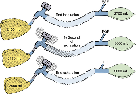
FIGURE 4-15 Mapleson A circuit, spontaneous breathing. Stippled areas indicate carbon dioxide–containing gas. Top, The end of a normal spontaneous inspiration for a normal adult patient. As the patient begins to exhale, carbon dioxide–free gas flows from the upper dead space, then carbon dioxide–rich gas flows into the corrugated tube and, together with continuing fresh gas flow (FGF), fills the bag a half second later (middle). The rest of the expirate goes out through the pop-off valve, along with carbon dioxide–containing gas in the tubing, which is pushed toward the pop-off valve by the fresh gas flow. Optimally, at end exhalation (bottom), the circuit has largely been flushed of carbon dioxide.
During assisted or controlled ventilation, two different things happen to decrease efficiency. First, the bag must be squeezed during inspiration, both to deliver the entire tidal volume (400 mL) and to vent the fresh gas flow that comes in over an entire respiratory cycle (in this case,  of 6 L/min, or 300 mL). Now all the exhaled tidal volume flows into the breathing tubing, followed by the continued fresh gas flow during the end-expiratory pause. During the next compression, some alveolar gas may reenter the airway until the circuit pressure rises to the threshold of the pop-off valve. Thereafter, some carbon dioxide and some fresh gas go both to the lung and to the pop-off valve. Understandably, the effect would depend on the rate of compression of the bag, that is, the inspiratory flow, lung and chest wall compliance, airway resistance, volume of dead space, I:E ratio, and fresh gas flow. Thus, during assisted ventilation, the Mapleson A circuit is far less efficient than during spontaneous ventilation in terms of preventing rebreathing.
Mapleson D Configurations and Carbon Dioxide Removal
A typical circuit for controlled ventilation is shown in Figure 4-16. The assumptions for this model are a fresh gas flow of 6 L/min; a minute volume of 10 L, using a VT of 1000 mL and respiratory rate of 10; an FRC of 2000 mL; an expiratory flow nearly exponential with a 0.5-second half-time; an I:E ratio of 1:2; and a peak inspiratory gas flow rate of 30 L/min. At inspiration the bag is squeezed to deliver 1000 mL to the patient in 2 seconds and to blow 600 mL out the pop-off valve. A total of 200 mL of fresh gas entered in these 2 seconds, which results in the state shown in the top panel of Figure 4-16.
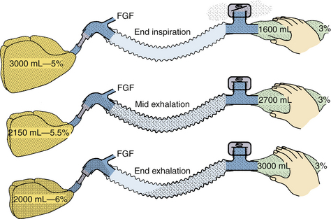
FIGURE 4-16 Mapleson D circuit, controlled breathing. At end inspiration, the anesthesiologist has squeezed the bag from its nominal volume of 3 L down to 1600 mL. Of this amount, 800 mL went into the patient’s lungs along with 200 mL of fresh gas; 600 mL of the bag’s contents, with about 3% carbon dioxide, left the circuit through the pop-off valve (top). During the next 2 seconds, the patient exhales nearly all of the tidal volume (900 mL); this, with the continuing fresh gas flow (FGF), fills the bag (middle). Because of the fresh gas flow, the bag’s carbon dioxide concentration content is diluted below alveolar gas. Furthermore, the patient’s expiratory flow diminishes toward the end-expiratory pause, and the fresh gas flows into the patient end of the circuit. This is the gas that will enter the patient’s lungs first on the next inspiration (bottom).
Two seconds after exhalation begins, the patient has exhaled 900 mL, which is diluted with 200 mL of fresh gas as it enters the circuit. This has refilled the bag to 2700 mL. In the next 2 seconds of exhalation, the rest of the tidal volume, 100 mL, and 200 mL more of fresh gas have filled the breathing tubing, and the bag has regained its initial volume of 3 L. The lungs now contain 6% carbon dioxide because this gas has been slowly increasing as a result of continued carbon dioxide delivery to a progressively smaller alveolar volume. The bag contains 3% carbon dioxide, but in the breathing tubing the concentration falls toward zero, the fresh gas fraction of inspired carbon dioxide (FiCO2). In fact, if two thirds of the fresh gas flow is washed into the lungs, it will provide 4 L/min of carbon dioxide–free alveolar ventilation, and the PACO2 will be normal despite obvious rebreathing of some carbon dioxide. In fact, studies of anesthetized patients show normal carbon dioxide homeostasis with a fresh gas flow of 70% of total minute ventilation in Mapleson D circuits during controlled breathing, if minute volume is 150 mL/kg or greater.12,110
Proprietary Semiclosed Systems
Although a variety of pieces of anesthesia hardware can be used to assemble Mapleson circuits A through F, several specific circuits with eponymous identities have been introduced that offer specific advantages. These include the Jackson-Rees, Bain, Lack, Mera F, and Humphrey ADE. The last four are conveniently coaxial; they have a tube-within-a-tube arrangement that moves the physical location of the fresh gas inflow and/or the expiratory valve away from the patient connection elbow while preserving the advantages of the A, D, or F circuits. The Bain and Lack circuits are shown in Figure 4-17.
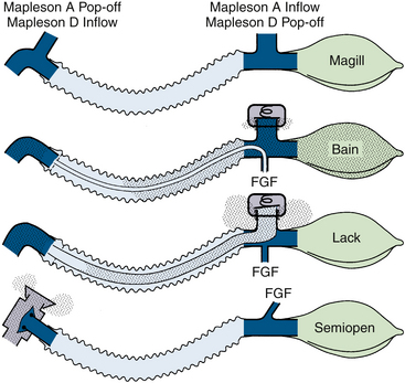
FIGURE 4-17 Comparison of the Mapleson A and D circuits with the Bain, Lack, and semiopen circuits. From the top, A schematic of the Mapleson A and D circuits with an indication for placement of the inflow and pop-off valves that distinguish A from D. The Bain circuit, shown at end expiration, uses a small-bore fresh gas delivery tube to deliver fresh gas to the patient end of the circuit. The Lack circuit looks similar externally, but the inner tube is now an expiratory limb that delivers exhaled gas to the pop-off valve at the bag end. In a semiopen circuit, the breathing tube is inspiratory and all exhaled gas exits at the valve. Only fresh gas is found in the tubing. FGF, fresh gas flow.
The Bain circuit is basically a coaxial Mapleson D design. Instead of a separate small-bore tube for delivery of fresh gas to the patient elbow, the delivery tube enters the corrugated expiratory tube near the bag mount and pop-off valve and runs coaxially to the patient end, where the end is secured by a plastic “spider” in the center of the tube. Thus fresh gas is delivered at the patient end, and the pop-off valve exhausts gas at the bag end of the corrugated tube, a Mapleson D arrangement. Various recommendations for fresh gas flow have been published. One commercial brand has a package insert that recommends a fresh gas flow of 100 mL/kg/min. Such recommendations often were based on an instantaneous inspired carbon dioxide concentration of zero for some portion of the cycle. However, with suitably augmented minute ventilation—150 mL/kg or more, instead of the 90 mL/kg for a normal person at rest—adequate carbon dioxide elimination results from a fresh gas flow of 70 mL/kg/min during assisted or controlled ventilation.12,33,110 Although not recommended for prolonged periods, spontaneous ventilation requires a greater fresh gas flow, up to 150 mL/kg/min.25,111,112
The Bain circuit may malfunction if the central tube (fresh gas delivery) becomes disconnected, either where it enters the corrugated outer tube or from its retaining spider at the patient end. Either disconnection effectively increases the apparatus dead space, and for any given minute volume, it reduces alveolar ventilation accordingly.113 Disconnection at the bag end is by far the more serious problem, and visual inspection alone may not identify the problem. Because of this, two tests have been proposed: one uses a very low oxygen flow (50 mL/min) and occlusion of the inner tube with a finger or plunger from a small disposable syringe114; the flowmeter bobbin should fall with occlusion of the inner tube. Alternatively, filling the reservoir bag with gas and operating the oxygen flush will normally create a Venturi effect that partially empties the bag.115
The Lack circuit (coaxial Mapleson A) appears similar to the Bain circuit externally. Near the bag are both a pop-off valve and a fresh gas inflow nipple. However, the central tube is larger in diameter and serves as an expiratory limb, leading from a spider that centers it coaxially to the pop-off valve.14 The circuit is long enough that this central tube has a volume of 500 mL. Fresh gas flows between the external corrugated tube and the central tube to the patient connection end. This is essentially a Mapleson A circuit and is optimal for spontaneous breathing. Figure 4-17 shows the Lack system at end expiration. The first part of exhalation has passed retrograde between the corrugated hose and inner tube toward the bag, which is simultaneously filling with fresh gas. Because this first part contains little or no carbon dioxide, little carbon dioxide is found in the outer channel. When the bag reaches its nominal volume, the pressure rises enough to open the pop-off valve; for the rest of exhalation, carbon dioxide–rich gas passes into the inner channel. If expiratory flow falls to nearly zero at the end-expiratory pause, fresh gas flows toward the patient through the outer channel and even into the inner tube, pushing alveolar gas out through the pop-off valve. Any carbon dioxide remaining in the inner tube is not rebreathed during the subsequent inspiration because the expiratory valve closes, and little gas flows backward in the inner (expiratory) tubing. Reports that the Lack system is more efficient, equally efficient, or less efficient than a Magill attachment may be found in the literature, but the differences are always slight.108,116,117 Fresh gas flow at 70% of minute volume results in negligible carbon dioxide rebreathing. It is important to note that with spontaneous breathing, increasing fresh gas flow is of little value in lowering arterial PCO2, which is set by the patient’s intrinsic respiratory control centers.
The original Humphrey ADE circuit was available as a coaxial volume or as a parallel circuit.118 A fixed, machine-mounted valve assembly with one control lever permitted selection of either a Mapleson A or D configuration. With modern anesthesia ventilators that exhaust excess gas at end expiration, the system in D mode becomes equivalent to a Mapleson E circuit, hence the suffix ADE.118 In the parallel setup, the Humphrey ADE can be used with or without a carbon dioxide absorber (Fig. 4-18). The disadvantage of forgetting to switch the lever and the ubiquitous circle systems in U.S. hospitals have led to greater interest outside than inside the United States. A notable exception is the work of Artru and Katz,119 who studied patients and used a rise in end-tidal rather than inspired carbon dioxide concentration as the criterion for rebreathing. They found that with an appropriate lever setting, an FGF of 66 mL/kg/min prevented an increase in end-tidal carbon dioxide during both spontaneous and controlled ventilation.
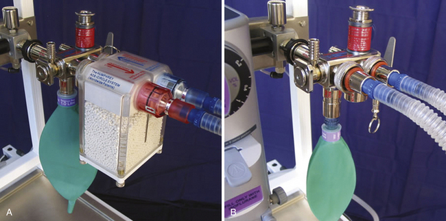
FIGURE 4-18 The Humphrey ADE system can be used with carbon dioxide absorbent (A) or without (B). (Courtesy Dr. D. Humphrey.)
Since the original concept of combining the benefits of the Magill, Lack, Bain, and T-piece into one universal unit in 1984, there have been significant improvements to the design and function of the Humphrey ADE system. A new exhaust valve has significantly improved function for spontaneous respiration and eliminated the necessity for a D mode (Fig. 4-19). This new valve also has allowed the T-piece mode for children to be superseded by use of the system in the much more efficient Mapleson A system. A detachable soda lime canister has been added, turning the system into a multipurpose apparatus.
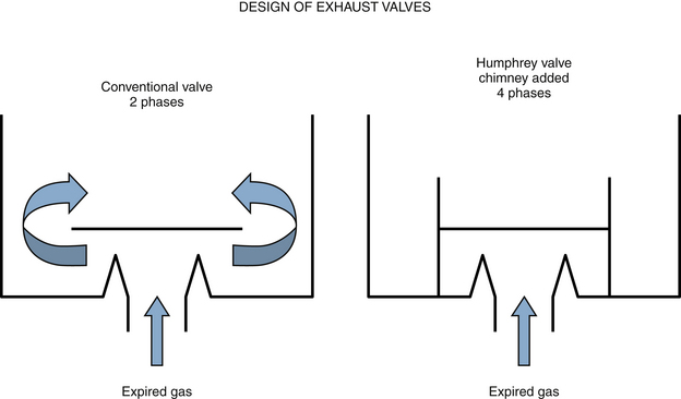
The efficiency of Mapleson A systems for spontaneous respiration depends on the preservation of unused dead space gas within the system during the early phase of exhalation and elimination of alveolar gas in the second half. Standard exhaust valves often open unpredictably, with significant loss of dead space gas, and there can be significant contamination by alveolar gas at the mixing interface within the tube. To prevent the loss of dead space by premature opening of the exhaust valve, a valve was designed that functions in four phases rather than two (i.e., simply open or closed).
The new valve is designed to always ensure that no exhaled gas is vented until the reservoir bag on the inspiratory limb is completely full, whether in the Mapleson A mode or with the soda lime canister. It has a 5-mm chimney encircling the knife edge on which the valve seat rests and a spring that exerts approximately 1 cm H2O pressure on the seat. When the patient exhales, any pressure within the system lifts the valve seat into the chimney, but the spring keeps it closed (phase 1). In the Mapleson A mode, the expiratory limb remains closed in phase 1, and all dead space gas consequently is preserved along the inspiratory limb, as is fresh gas within the reservoir bag. In mid-exhalation, alveolar gas now flows into the inspiratory limb; at this point, the bag fills completely and the pressure rises within the system. The valve seat now lifts above the chimney to open the valve, allowing it to vent what is now alveolar gas (phase 2). Once open, the valve acts a variable orifice offering almost no resistance to flow. At this stage, mixing at the interface between alveolar gas and dead space is reduced by the use of 15-mm parallel smooth bore tubes (less turbulence and mixing) rather than coaxial or corrugated tubing. A “flip-flop” design Y-patient connector also helps direct the flow of alveolar gas into the expiratory limb. Exhalation continues with venting of alveolar gas through the exhaust valve until the falling pressure allows the valve seat to drop back into the chimney to close the valve (phase 3). At this point, there is a small backpressure (PEEP) within the system, preventing possible alveolar collapse that can occur under anesthesia, especially in children and the elderly. Exhalation is now complete. During the inspiratory phase (phase 4) the valve is completely closed, shutting off the expiratory limb. The patient can now breathe only from the inspiratory limb, the first part being warmed, humidified dead space gas. The fresh gas flow required is approximately equal to that needed to vent alveolar gas. Under anesthesia, this can be as low as 50% of respiratory minute volume.
The significant difference from standard valves is that the efficient function of the new valve is ensured and does not vary from patient to patient or with variable respiratory patterns. The valve cap is always fully open because it functions automatically. With almost no impedance to flow and being easy to breathe through, the design of this valve is such that it is appropriate for pediatric anesthesia. The PEEP effect also is beneficial for children. It was a logical step that such a valve could be used in the Mapleson A mode for spontaneous respiration in children.120 In this more efficient mode, fresh gas flows can be reduced to approximately one fourth of that required for the T-piece,120 and a scavenging tube is conveniently connected to the exhaust valve well away from the patient. The dead space gas adds beneficial heat and moisture to the system. The ADE system became a standard system for pediatrics in 1996 in the United Kingdom. Consequently, the Mapleson A mode is used for both adults and children, simplifying the concept of a multipurpose system.
To facilitate manual ventilation, the stem of the valve seat has been extended out of the top of the valve. Manual downward pressure on the stem closed off the valve such that the bag could be squeezed to assist ventilation manually without having to screw the valve cap down. Interestingly, the altered gas dynamics within the system proved to be more efficient than the Mapleson D mode.121 For automatic ventilation, the exhaust valve and reservoir bag are automatically excluded by the lever, which, at the same time, brings in the ventilator connection. This is a safe design because forgetting to switch it causes the ventilator to sound immediately (high pressure obstruction alarm signal).
In summary, in the semiclosed mode, the Humphrey ADE system is now used in the Mapleson A mode for spontaneous respiration and manual ventilation for adults and children, while configuratively it is simply two tubes for automatic ventilation (Mapleson E). (The term ADE system is retained to indicate both adult and pediatric use because there is no longer a D mode.) The simplicity of the system is that the lever automatically switches between these modes. The more popular version uses parallel rather than coaxial tubing.
Finally, the introduction of the detachable soda lime canister to the original ADE system in 1999 added a new dimension to allow recycling by the absorption of carbon dioxide and included a better design of the circle system. The four-phase exhaust valve (although fully open) stays closed during exhalation such that exhaled gas is automatically recycled back to the reservoir bag until the bag is fully distended. Only then does it open to vent any excess exhaled gas. By positioning the reservoir bag on the inspiratory limb, fresh gas is efficiently preserved into this bag during the expiratory phase. (In contrast, when the bag is positioned on the expiratory limb on alternative equipment, fresh gas is forced backward through the canister and is potentially lost from the system.) The lever operates in the same way, switching between spontaneous, manual, and controlled ventilation. The anesthesiologist thus has two basic decisions to make: to use the Humphrey ADE system in a semiclosed mode or with the recycling soda lime canister, and to set the system for spontaneous and manual ventilation (lever up) or for automatic ventilation (lever down).
The Mera F system, introduced in Japan in 1978, uses a modern circle canister-valve assembly as the mounting for a coaxial Bain-type circuit. Byrick and colleagues112 found that at 100 mL/kg/min fresh gas flow, the Mera F functioned as well as the standard Bain circuit. During controlled respiration, this flow kept PACO2 at 45 ± 9 mm Hg during light anesthesia, despite a lower minute volume, because of a slightly improved capture of dead space gas for reinspiration. The Mera F tubing is quite suitable for the Humphrey ADE single-lever hardware.
The Universal F system (King Systems, Noblesville, IN) is essentially equivalent in design and function to the Japanese Mera F and is based on the same patents, but it is manufactured and available in the United States (Fig. 4-20, A). It also uses a coaxial arrangement and mounts on standard circle system hardware. Differences from the Mera F include larger diameter inspiratory and expiratory tubing to decrease resistance, corrugation of the inspiratory tube to prevent kinking, and the ability to be used as a transport system. When used with circle system hardware, the Universal F system is functionally no different than a standard circle system circuit, with the exception that the inspiratory limb is enclosed by the expiratory limb for the purpose of uncluttering the tubing apparatus and providing improved humidification of inspired gas. For patient transport, the Universal F system can be converted to a Bain circuit by the attachment of an oxygen source to the inspiratory limb and a reservoir bag with a pop-off valve to the expiratory limb (Fig. 4-20, C). As with a standard Bain circuit, it is important that a fresh gas flow appropriate for the mode of ventilation being used be supplied when using this circuit for transport (70 to 100 mL/kg/min for controlled ventilation and ≤150 mL/kg/min for spontaneous ventilation). Following transport, this system can function as part of a nonrebreathing system on an intensive care unit ventilator.
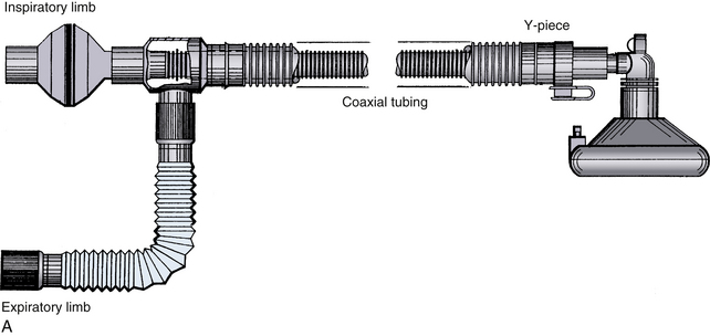
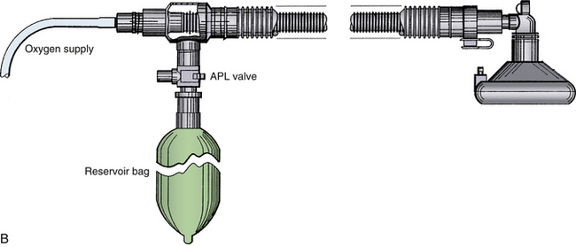
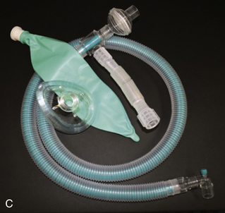
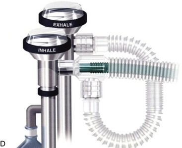
FIGURE 4-20 A and B, The Universal F circuit, a coaxial system that can be mounted on standard circle system hardware. C, Universal F circuit with circle system adaptor tubing. Note the green inner hose carries the inspiratory gases. The circuit can be adapted for patient transport by adding an oxygen supply source to the inspiratory limb and a reservoir bag and pop-off valve to the expiratory limb. D, The Universal F circuit attached to the circle system. APL, adjustable pressure-limiting valve. (Courtesy King Systems, Noblesville, IN.)
The Enclosed Afferent Reservoir (EAR) breathing system (Fig. 4-21) reflects an attempt to create a semiclosed system that retains efficiency during both spontaneous and controlled ventilation without the use of switching valves. Use of the term afferent denotes a system in which the reservoir is located on the portion of the system closely associated with the fresh gas supply. Mapleson A systems, including the Lack system, are afferent reservoir systems; they preferentially exhaust alveolar gas during the expiratory phase of spontaneous respiration, but with controlled ventilation, the pop-off opens during inspiration as well, which limits efficiency. Efferent systems have the reservoir closely associated with the pop-off valve and include Mapleson systems D through F. As previously noted, they are most efficient during controlled ventilation. An enclosed afferent system prevents venting of gas from the expiratory valve during controlled inspiration by enclosing the reservoir in a chamber; as pressure in the chamber is increased to deliver a breath, the expiratory valve is forced to close. It has been demonstrated that efficiency during controlled ventilation using the EAR system is similar to that of the Bain.122 During spontaneous ventilation, the EAR system is essentially identical to the Mapleson A. In adults, it is suggested that a fresh gas flow of 70 mL/kg is sufficient to prevent rebreathing during controlled ventilation with the EAR system.123 Appropriate fresh gas flow during spontaneous ventilation using the EAR in adults can vary and are best determined by clinical assessment, but in a mathematical model, a value greater than 0.86 times the minute ventilation has been shown to prevent rebreathing.124 In children, a fresh gas flow equal to 0.6 times the weight of the child has been demonstrated to provide normocapnia to mild hypocapnia regardless of the mode of ventilation.125
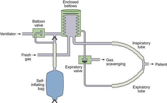
FIGURE 4-21 The enclosed afferent reservoir breathing system. This system functions like a Mapleson A system during spontaneous ventilation, but efficiency during controlled ventilation is improved by closure of the expiratory valve on delivery of a breath from the self-inflating bag, preventing wasting of fresh gas. This occurs because the same pressure increase that forces the bellows downward also inflates a balloon in the expiratory valve, causing the valve to close. (From Droppert PM, Meakin G, Beatty PC, etal: Efficiency of an enclosed afferent reservoir breathing system during controlled ventilation. Br J Anaesth 1991;66:638-642.)
The Jackson-Rees breathing circuit is a modification of Ayre’s T-piece, which is used in pediatric anesthesia worldwide. It adds a corrugated tube, a bag, and sometimes a variable, spring-loaded valve to the expiratory limb of the T-piece. Mapleson added it to his classification system as “F” in 1975.26 Nightingale and colleagues23 have pointed out that if the volume of the expiratory limb exceeds the tidal volume, Mapleson D, E, and F systems function identically during spontaneous breathing and should be supplied with a fresh gas flow of 100 mL/kg/min or more. Further, if the Jackson-Rees system is assembled with a spring-loaded valve in the tail of the bag, it becomes a Mapleson D and can be used with controlled ventilation with a fresh gas flow of 70 mL/kg/min.
Semiopen Systems
Semiopen systems, also known as nonrebreathing systems, eliminate carbon dioxide by use of two valves that exclude rebreathing. The reservoir bag contains pure fresh gas, which must be supplied at rates at or above the current respiratory minute volume. Apparatus dead space is minimized if the pair of valves, one opening on inspiration and one on exhalation, are incorporated into one small-volume assembly near the mask or tracheal tube (see Fig. 4-5, B). The valves must be designed to open with little pressure and to close quickly with the change in gas flow between inspiration and expiration. Clever design permits the pressure gradient across the inspiratory valve to positively close the expiratory valve, making transition from spontaneous to controlled breathing automatic; all the anesthesiologist has to do is squeeze the bag. The Frumin and Fink valves were once commonly used in anesthesia, and Ruben valves and others still find application in self-inflating resuscitator bag valve assemblies. Most mechanical ventilators used postoperatively and in ICUs also use such circuits, actively closing the expiratory valve by the machine pressure generated to start inspiration. Gas masks and scuba gear are other examples of nonrebreathing circuits, as were the intermittent-flow anesthesia machines of earlier times. The major advantages of semiopen circuits were the relative accuracy of flowmeters at high gas flow, ensuring inspired gas concentrations, and the ability to measure respiratory minute volume by setting fresh gas flow to keep the breathing bag just partly distended at each end expiration. With instrumentation currently available, neither advantage is of much value. Semiopen systems could be heated, humidified, and scavenged as readily as could semiclosed systems,44,126-129 but often they required a higher fresh gas flow, typically 80 to 100 mL/kg/min.
Positive End-Expiratory Pressure
To improve oxygenation, the application of PEEP to a breathing system may be required. PEEP may be achieved either by adding a freestanding mechanical PEEP valve, such as a Boehringer valve (Boehringer Laboratories, Wynnewood, PA) between the expiratory limb of a circle system and the expiratory unidirectional valve (Fig. 4-22) or, in the case of the Datex-Ohmeda 7900 ventilator, by electronically regulating pressure on the expiratory valve by means of precision-controlled gas flow from the bellows. A schematic of a mechanical add-on PEEP valve is shown in Figure 4-23. A weighted ball must be lifted off its seat by the gas flow. The weight of the ball determines the amount of PEEP. Valves are available for application of various levels of PEEP, including 2.5, 5, 10, 15, and 20 cm H2O. Such valves can be used in series to create any desired level of PEEP. It is essential that they be placed correctly—that is, vertically—in the expiratory limb (Fig. 4-23, B). Placement in the inspiratory limb would completely obstruct the circuit (see Chapter 30). Also, if not mounted vertically, they can malfunction. The use of add-on mechanical PEEP valves with the 7900 ventilator is not recommended because this could cause errors in the electronic control of PEEP, pressure, and flow by the ventilator.
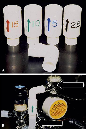
FIGURE 4-22 A, Freestanding weighted ball positive end-expiratory pressure (PEEP) valves and elbow adapter. B, Freestanding PEEP valve correctly positioned vertically between the expiratory limb of the circuit (bottom arrow) and the expiratory unidirectional valve (top arrow).
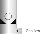
FIGURE 4-23 Weighted-ball design freestanding positive end-expiratory pressure valve. This valve is designed to be mounted vertically in the expiratory limb of a circle just upstream of the exhalation unidirectional valve.
“Electronic PEEP,” as supplied by the 7900 ventilator, is available only during mechanical ventilation because it relies on the function of the bellows to operate. In theory, a mechanical PEEP valve could be added to the circuit during bag-mode ventilation only, but this could result in ventilator errors if the valve is left in place after switching to the ventilator mode. Because the PEEP is controlled precisely by a computer-operated flow control valve, an advantage of electronic PEEP is that any gas leak from the airway can be compensated for by increasing airway pressure from the bellows. The result is a stable, repeatable, calibrated PEEP level.
Dräger Medical offers mechanical PEEP valves as an optional part of their Narkomed anesthesia breathing systems, as does Datex-Ohmeda as part of the 7800 and earlier machines. These valves are purpose-designed and built into the system to prevent erroneous placement. The Ohmeda mechanical PEEP valve is essentially a spring-loaded, expiratory, unidirectional valve that is adjustable between 2 and 20 cm H2O (Fig. 4-24). It is essential that the PEEP valve be installed only on the exhalation unidirectional valve, never on the inhalation valve. Thus, in Figure 4-4, if an adjustable spring were to be placed between the valve disk and the dome, it would tend to prevent the opening of the disk, thereby requiring a higher pressure upstream for gas to flow across the valve. Adjusting the spring tension with the calibrated knob thereby adjusts the level of PEEP applied to the circuit between the inspiratory valve and the expiratory, unidirectional PEEP valve, as was the case in the old Ohmeda GMS Absorber. In that system, the pressure in the circuit is sensed just downstream of the inspiratory unidirectional valve so that the circuit pressure gauge and any alarms will detect the presence of PEEP in the circuit (see also Chapters 9 and 30).
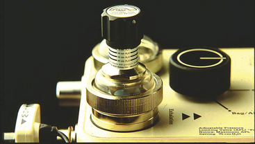
FIGURE 4-24 Ohmeda positive end-expiratory pressure valve (GE Healthcare, Waukesha, WI). It it essentially a spring-loaded expiratory unidirectional valve.
With an old Ohmeda GMS absorber in the APL or bag mode, and with the patient breathing spontaneously, the setting on the APL valve must be higher than the PEEP setting. If it is not, inadequate tidal volumes may be delivered to the patient during inspiration. Ohmeda also warns that the PEEP valve should be installed into the GMS absorber only when the use of PEEP is anticipated for that case. It should be removed when not in use; otherwise, deposits from the breathing circuit can collect in the valve mechanism and cause it to malfunction (see also Chapter 30).130 The use of PEEP in the patient circuit may result in a significant decrease in delivered tidal volume. Factors that influence the tidal volume delivered to the patient include patient circuit pressure (affected by PEEP), compliance, and resistance. The ventilation must be appropriately adjusted to compensate for any decrease in tidal volume caused by the addition of PEEP.131
The Narkomed delivery systems use a PEEP valve based on magnetic principles. Instead of using the force of a weighted ball or a spring, the force of attraction between two magnets is used to adjust the pressure needed to open the valve (Fig. 4-25). Because this valve is located between the patient circuit and the selector block that houses the switch for manual (bag) or automatic (ventilator) mode, it must permit bidirectional gas flow so that during inspiration gas flows from the reservoir bag or ventilator bellows, through the valve, and to the patient circuit via a spring-loaded, one-way valve (Fig. 4-26). On exhalation, the one-way inspiratory valve closes, and gas pressure must now overcome the force of attraction between the two magnets to open the magnetic valve and flow to the bag or ventilator bellows (Figs. 4-27 and 4-28). This PEEP valve is not calibrated, but the knob is marked to show direction of rotation for increasing or decreasing PEEP. A slide switch is incorporated into the latest version of this valve to control and clearly indicate whether the PEEP valve is on or off (Fig. 4-29).
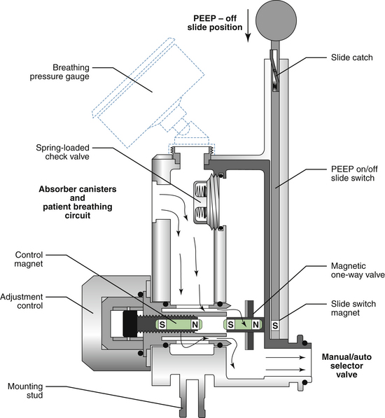
FIGURE 4-25 The Narkomed positive end-expiratory pressure (PEEP) valve actually contains two valves, one magnetic and one spring loaded, that affect the flow of gas in the patient breathing circuit during exhalation. In this diagram, the PEEP valve is in the off position because the slide switch is moved down, placing a magnet in opposition to the magnetic one-way valve. Because the slide-switch magnet is stronger than the control magnet, the magnetic one-way valve is held in a fully open position. Thus, during exhalation, gas flows from the patient through the magnetic one-way valve unopposed, creating no PEEP. N and S refer to the north and south poles of the magnets. (Courtesy Dräger Medical, Telford, PA.)
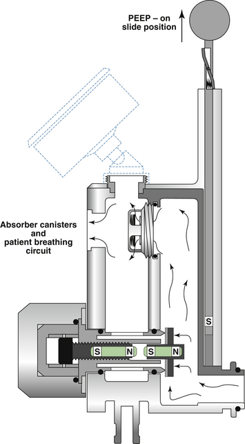
FIGURE 4-26 The Narkomed positive end-expiratory pressure (PEEP) valve in the on position during inspiration. Gas cannot flow through the closed magnetic valve and instead flows unopposed to the patient through the one-way check valve. N and S refer to the north and south poles of the magnets. (Courtesy Dräger Medical, Telford, PA.)
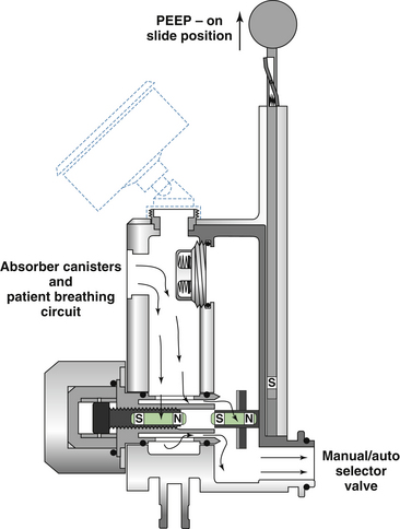
FIGURE 4-27 The Narkomed positive end-expiratory pressure (PEEP) valve in the on position at the beginning of exhalation. Gas from the patient cannot flow through the one-way check valve, so it creates pressure in the valve apparatus that eventually forces open the magnetic valve. N and S refer to the north and south poles of the magnets. (Courtesy Dräger Medical, Telford, PA.)
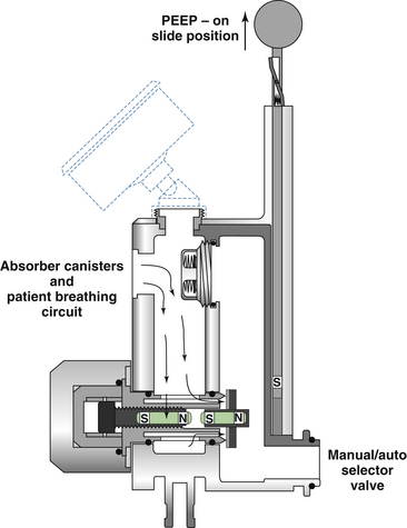
FIGURE 4-28 The Narkomed positive end-expiratory pressure (PEEP) valve in the on position at the end of exhalation. When the pressure of the exhaled gases decreases to a level insufficient to oppose the attraction of the control magnet to the magnetic valve, the magnetic valve closes. Gas is no longer allowed to escape from the patient’s lungs, creating PEEP. The level of PEEP is increased by turning the adjustment knob such that the control magnet is moved closer to the magnetic valve, increasing the force of attraction and closing the valve earlier in exhalation. N and S refer to the north and south poles of the magnets. (Courtesy Dräger Medical, Telford, PA.)
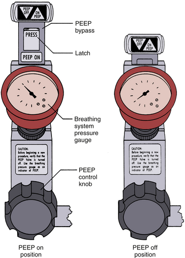
FIGURE 4-29 The Narkomed positive end-expiratory pressure (PEEP) valve slide switch to indicate and control the on/off function of the PEEP valve. (Courtesy Dräger Medical, Telford, PA.)
The location of the PEEP valve in relation to the expiratory unidirectional valve (freestanding valve or Datex-Ohmeda PEEP valve) or in the manual/automatic switch block (Dräger) permits application of PEEP to the patient circuit during all modes of ventilation: spontaneous, assisted, controlled, and automatic. In this location, the circuit pressure gauge and alarms sensing pressure at the absorber will detect the presence and level of PEEP applied (see also Chapter 30).
Circuit Malfunction and Safety
Despite continued improvement in the design and function of anesthesia machines and related equipment, accidents resulting from their misuse or malfunction continue to occur.131-134 A 1997 American Society of Anesthesiologists Closed Claims Project analysis of 3791 claims from 1961 to 1994 revealed that the most common source of injury related to gas delivery equipment was the breathing circuit and that the breathing circuit continues to be a source of anesthesia claims.135 Preventable anesthesia mishaps are largely due to equipment failures or misuse. Despite the relative complexity of anesthesia gas delivery equipment, equipment misuse was found in the ASA analysis to be three times more frequent as a cause of injury than equipment failure. Interestingly, the breathing circuit, a relatively simple component of the gas delivery system, contributed to misuse more than any other component. The majority of claims related to breathing circuit misuse were attributable to either misconnections or disconnections. Rare causes included leak, valve failure, and carbon dioxide absorber defect. As previously mentioned, the bacterial filter has also been implicated as a source of problems within the breathing system.90-94,96
From these and similar analyses come important recommendations that anesthesiologists and manufacturers of anesthesia equipment should heed. First, anesthesiologists must be thoroughly familiar with and understand the function of the equipment they use. Second, a routine for checking equipment before using it each time is essential. Third, the design of a piece of equipment should be as simple as possible; needless elaboration may confuse the user and detract from the basic utility of the device. In fact, some have suggested that a fundamental reevaluation of breathing circuit design may be in order.106 Finally, not all potential equipment malfunctions or errors in their use can be anticipated; anesthesiologists must be constantly vigilant for their possible occurrence and must be prepared to manage their consequences (see also Chapter 30).
References
1. Jackson D.E. A new method for the production of general analgesia and anesthesia with a description of the apparatus used. J Lab Clin Med. 1915;1:1–12.
2. Waters R.M. Clinical scope and utility of carbon dioxide filtration in inhalation anesthesia. Anesth Analg. 1924;3:20–26.
3. Waters R.M. Carbon dioxide absorption technique in anesthesia. Ann Surg. 1936;103:38–45.
4. Sword B.C. The closed circle method of administration of gas anesthesia. Anesth Analg. 1930;9:198–202.
5. The Sodasorb manual of carbon dioxide absorption. New York, 1974, WR Grace & Co, Dewey and Almy Chemical Division.
6. Fink B.R. A non-rebreathing valve of new design. Anesthesiology. 1954;15:471–474.
7. Mapleson W.W. The elimination of rebreathing in various semiclosed anaesthetic systems. Br J Anaesth. 1954;26:323–332.
8. Sykes M.K. Rebreathing circuits: a review. Br J Anaesth. 1968;40:666–674.
9. Stephen C.R., Slater H.M. A nonresisting nonrebreathing valve. Anesthesiology. 1948;9:550–552.
10. Ruben H. Anaesthesia system with eliminated spill valve adjustment and without lung rupture risk. Acta Anaesthesiol Scand. 1984;28:310–314.
11. Frumin M.J., Lee A.S.J., Papper E.M. New valve for non-rebreathing systems. Anesthesiology. 1959;20:383–385.
12. Bain J.A., Spoerel W.E. A streamlined anaesthetic system. Can Anaesth Soc J. 1972;19:426–435.
13. Dixon J., Chakrabarti M.K., Morgan M. An assessment of the Humphrey ADE anaesthesia system in the Mapleson A mode during spontaneous ventilation. Anaesthesia. 1984;39:593–596.
14. Lack J.A. Theatre pollution control. Anaesthesia. 1976;31:259–262.
15. Kay B., Beaty P.C.W., Healy T.E.J., et al. Change in the work of breathing imposed by five anaesthetic breathing systems. Br J Anaesth. 1983;55:1239–1246.
16. Hamilton W.K. Nomenclature of inhalation anesthetic systems. Anesthesiology. 1964;25:3–5.
17. Tenpas R.H., Brown E.S., Elam J.O. Carbon dioxide absorption: the circle versus the to-and-fro. Anesthesiology. 1958;19:231–239.
18. Eger E.I., Ethans C.T. The effects of inflow, overflow and valve placement on economy of the circle system. Anesthesiology. 1968;29:93–100.
19. Brown E.S., Seniff A.M., Elam J.O. Carbon dioxide elimination in semiclosed systems. Anesthesiology. 1964;25:31–36.
20. de Silva A.J.C. Normocapnic ventilation using the circle system. Can Anaesth Soc J. 1976;23:657–666.
21. Keenan R.L., Boyan C.P. How rebreathing anaesthetic systems control PaCO2: studies with a mechanical and a mathematical model. Can Anaesth Soc J. 1978;25:117–121.
22. Ladegaard-Petersen H.J. A circle system without carbon dioxide absorption. Acta Anaesthesiol Scand. 1978;22:281–286.
23. Nightingale D.A., Richards C.C., Gress A. An evaluation of rebreathing in a modified T-piece system during controlled ventilation of anaesthetized children. Br J Anaesth. 1965;37:762–771.
24. Steen S.N., Chen J.L. Automatic non-rebreathing valve circuits: some principles and modifications. Br J Anaesth. 1963;35:379–382.
25. Spoerel W.E. Rebreathing and end-tidal CO2 during spontaneous breathing with the Bain circuit. Can Anaesth Soc J. 1983;30:148–154.
26. Willis B.A., Pender J.W., Mapleson W.W. Rebreathing in a T-piece: volunteer and theoretical studies of the Jackson-Rees modification of Ayre’s T-piece during spontaneous respiration. Br J Anaesth. 1975;47:1239–1246.
27. Feeley T.W., Hamilton W.K., Xavier B., et al. Sterile anesthesia breathing circuits do not prevent postoperative pulmonary infection. Anesthesiology. 1981;54:369–372.
28. ParmLey J.B., Tahir A.H., Dascomb H.E., et al. Disposable versus reusable rebreathing circuits: advantages, disadvantages, hazards and bacteriologic studies. Anesth Analg. 1972;51:888–894.
29. Berry F.A., Eastwood D.W. Serious defects in “simple” equipment. Anesthesiology. 1967;28:471.
30. Cozantis O.A., Tahkuman O. Aneurysm of ventilator tubing. Anaesthesia. 1971;26:235–236.
31. Bushman J.A., Collins J.M. The estimation of gas losses in ventilator tubing. Anaesthesia. 1967;22:664–667.
32. Proctor D.F. Studies of respiratory air flow: resistance to air flow through anesthetic apparatus. Bull Johns Hopkins Hosp. 1955;96:49–58.
33. Spoerel W.E. Rebreathing and carbon dioxide elimination with the Bain circuit. Can Anaesth Soc J. 1980;27:357–361.
34. Wang J.S., Hung W.T., Lin C Y. Leakage of disposable breathing circuits. J Clin Anesth. 1992;4:111–115.
35. Foregger R. The classification and performance of respiratory valves. Anesthesiology. 1959;20:296–308.
36. Hunt K.H. Resistance in respiratory valves and canisters. Anesthesiology. 1955;16:190–205.
37. Eger E.I., 2nd. Anesthetic systems: construction and function. In: Eger E.I., 2nd., eds. Anesthetic uptake and action. Baltimore: Williams and Wilkins, 1974.
38. Dogu T.S., Davis H.S. Hazards of inadvertently opposed valves. Anesthesiology. 1970;33:122–123.
39. Hirano T., Saito T. A new automatic nonrebreathing valve. Anesthesiology. 1969;31:84–85.
40. Horn B. Valve for assisted or controlled ventilation. Anesthesiology. 1960;21:83.
41. Lewis G. Nonrebreathing valve. Anesthesiology. 1956;17:618–619.
42. Newton G.W., Howill W.K., Stephen C.R. A piston-type nonrebreathing valve. Anesthesiology. 1955;16:1037–1038.
43. Ruben H. A new nonrebreathing valve. Anesthesiology. 1955;16:643–645.
44. Stephen C.R., Slater H.M. A nonrebreathing mask. Anesthesiology. 1952;13:226–229.
45. Loehning R.W., Davis G., Safar P. Rebreathing with “nonrebreathing valves.”. Anesthesiology. 1964;25:854–856.
46. Redick L.F., Dunbar R.W., MacDougal D.C., et al. An evaluation of hand operated self-inflating resuscitation equipment. Anesth Analg. 1970;49:28–32.
47. Wisborg K., Jacobsen E. Functional disorders of Ruben and Ambu-E valves after dismantling and cleaning. Anesthesiology. 1975;42:633–634.
48. Johnston R.E., Smith T.C. Rebreathing bags as pressure limiting devices. Anesthesiology. 1973;38:192–194.
49. Waters D.J. Use and misuse of a pressure-limiting bag. Anaesthesia. 1967;22:322–325.
50. Woolmer R., Lind B. Rebreathing with a semiclosed system. Br J Anaesth. 1954;26:316–322.
51. Lecky J.H. The mechanical aspects of anesthetic pollution control. Anesth Analg. 1977;56:769–774.
52. Lee S. A new popoff valve. Anesthesiology. 1964;25:240–242.
53. Linker G.S., Holaday D.A., Waltuck B. A simply constructed automatic pressure relief valve. Anesthesiology. 1970;32:563–564.
54. Mitchell J.V., Epstein H.G. A pressure-operated inflating valve. Anaesthesia. 1966;21:277–281.
55. Smith R.H., Volpitto P.P. Volume ventilator valve. Anesthesiology. 1959;20:885–886.
56. Brown E.S. Elam JO: Practical aspects of carbon dioxide absorption. NY State J Med. 1955;55:3436–3442.
57. Murray J.M., Renfrew C.W., Bedi A., et al. Amsorb: a new carbon dioxide absorbent for use in anesthetic breathing systems. Anesthesiology. 1999;91:1342–1348.
58. Kharasch E.D., Powers K.M., Artru A.A. Comparison of Amsorb, sodalime, and Baralyme degradation of volatile anesthetics and formation of carbon monoxide and compound A in swine invivo. Anesthesiology. 2002;96:173–182.
59. Adriani J., Rovenstine E.A. Experimental studies in carbon dioxide absorbers for anesthesia. Anesthesiology. 1941;2:1–19.
60. Brown E.S. The activity and surface area of fresh soda lime. Anesthesiology. 1958;19:208–212.
61. Brown E.S. Voids, pores and total air space of carbon dioxide absorbents. Anesthesiology. 1958;19:1–6.
62. Brown E.S., Bakamjian V., Seniff A.M. Performance of absorbents: effects of moisture. Anesthesiology. 1959;20:613–617.
63. Wallin R.F., Regan B.M., Napoli M.D., et al. Sevoflurane: a new inhalational anesthetic agent. Anesth Analg. 1975;54:758–765.
64. Morio M., Fujii K., Satoh N., et al. Reaction of sevoflurane and its degradation products with soda lime: toxicity of the byproducts. Anesthesiology. 1992;77:1155–1164.
65. Gonsowski C.T., Laster D.V.M., Eger E.I., 2nd., et al. Toxicity of compound A in rats: effect of a 3-hour administration. Anesthesiology. 1994;80:556–565.
66. Gonsowski C.T., Laster D.V.M., Eger E.I., 2nd., et al. Toxicity of compound A in rats: effect of increasing duration of administration. Anesthesiology. 1994;80:566–573.
67. Eger E.I., II., Koblin D.D., Bowland T., et al. Nephrotoxicity of sevoflurane versus desflurane anesthesia in volunteers. Anesth Analg. 1997;84:160–168.
68. Bito H., Ikeuchi Y., Ikeda K. Effects of low-flow sevoflurane anesthesia on renal function: comparison with high-flow sevoflurane anesthesia and low-flow isoflurane anesthesia. Anesthesiology. 1997;86:1231–1237.
69. Kharasch E.D., Frink E.J., Zagar R., et al. Assessment of low-flow sevoflurane and isoflurane effects on renal function using sensitive markers of tubular toxicity. Anesthesiology. 1997;86:1238–1253.
70. Fang Z.X., Knadel L., Laster M.J., et al. Factors affecting production of compound A from the interaction of sevoflurane with Baralyme and soda lime. Anesth Analg. 1996;82:775–781.
71. Ruzicka J.A., Hidalgo J.C., Tinker J.H., et al. Inhibition of volatile sevoflurane degradation product formation in an anesthesia circuit by a reduction in soda lime temperature. Anesthesiology. 1994;81:238–244.
72. Frink E.J., Malan T.P., Morgan S.E., et al. Quantification of the degradation products of sevoflurane in two CO2 absorbents during low-flow anesthesia in surgical patients. Anesthesiology. 1992;77:1064–1069.
73. Middleton V., Poznak A.V., Artusio J.F., et al. Carbon monoxide accumulation in closed circle anesthesia systems. Anesthesiology. 1965;26:715–719.
74. Fang Z.X., Eger E.I., 2nd., Laster M.J., et al. Carbon monoxide production from the degradation of desflurane, enflurane, isoflurane, halothane, and sevoflurane by soda lime and Baralyme. Anesth Analg. 1995;80:1187–1193.
75. Moon R.E., Meyer A.F., Scott D.L., et al. Intraoperative carbon monoxide toxicity [abstract]. Anesthesiology. 1990;73:A1049.
76. Moon R.E., Ingram C., Brunner E.A., et al. Spontaneous generation of carbon monoxide within anesthetic circuits [abstract]. Anesthesiology. 1991;75:A873.
77. Hampson N.B. Noninvasive pulse CO-oximetry expedites evaluation and management of patients with carbon monoxide poisoning. Am J Emerg Med. 2012;30:2021–2024.
78. Roth D., Herkner H., Schreiber W., et al. Accuracy of noninvasive multiwave pulse oximetry compared with carboxyhemoglobin from blood gas analysis in unselected emergency department patients. Ann Emerg Med. 2011;58:74–79.
79. Baxter P.J., Kharasch E.D. Rehydration of desiccated Baralyme prevents carbon monoxide formation from desflurane in an anesthesia machine. Anesthesiology. 1997;86:1061–1065.
80. Kitborn M.G. Preliminary clinical report on a new carbon dioxide absorbent—Baralyme. Anesthesiology. 1941;2:621–637.
81. Holloway A.M. Possible alternatives to soda lime. Anaesth Intens Care. 1994;22:359–362.
82. West J.B. Oxygen enrichment of room air to relieve the hypoxia of high altitude. Respiration Physiology. 1995;99:225–232.
83. Anonymous. Oxygen concentrators. Health Devices. 1993;22:3–24.
84. Fee JPH, Murray JM, Luney SR: Molecular sieves: an alternative method of carbon dioxide removal which does not generate compound A during simulated low-flow anaesthesia. Anaesthesia 50:841–845.
85. Poulton B.B., Foubert L., Klinowski J., et al. Extraction of nitric oxide and nitrogen dioxide from an oxygen carrier using molecular sieve 5A. Br J Anaesth. 1996;77:534–536.
86. Revell D.G. An improved circulator for closed circle anaesthesia. Can Anaesth Soc J. 1959;6:104–107.
87. Neff W.B., Burke S.F., Thompson R. A venturi circulator for anesthetic systems. Anesthesiology. 1968;29:838–841.
88. Eger E.I., Hamilton W.K. Positive-negative pressure ventilation with a modified Ayre’s T-piece. Anesthesiology. 1958;19:611–618.
89. Hogarth I. Anaesthetic machine breathing system contamination and the efficacy of bacterial/viral filters. Anesth Intens Care. 1996;24:154–163.
90. Chant K., Kociuba K., Munro R., et al. Investigation of possible patient-to-patient transmission of hepatitis C in hospital. NSW Pub Health Bull. 1994;5:47–51.
91. American Society of Anesthesiologists: Recommendations for infection control for the practice of anesthesiology, ed 3, 1998, Available at www.asahq.org
92. Smith C., Otworth D., Kaluszyk P. Bilateral tension pneumothorax due to defective anaesthesia breathing circuit filters. J Clin Anaesth. 1991;3:9–34.
93. McEwan A., Dowell L., Karis J. Bilateral tension pneumothorax caused by a blocked filter in the anesthesia breathing circuit. Anesth Analg. 1993;76:440–442.
94. Kopman A., Glaser L. Obstruction of bacterial filters by edema fluid. Anesthesiology. 1976;44:169–170.
95. Barton R. Detection of expiratory antibacterial filter occlusion. Anesth Analg. 1993;77:197.
96. Buckley P. Increase in resistance of in-line breathing filters in humidified air. Br J Anaesth. 1984;56:637–643.
97. Schwartz A., Howse J., Ellison N. The gas line filter: a cause for hypoxia. Anesth Analg. 1980;59:617–618.
98. Komesaroff D. Disposable and autoclavable circuits: the future is now. Anaesth Intens Care. 1996;24:173–175.
99. Harper M., Eger E.l., 2nd. A comparison of the efficiency of three anesthesia circle systems. Anesth Analg. 1976;55:724–729.
100. Neufeld P.D., Johnson D.L. Results of the Canadian Anaesthetists’ Society opinion survey on anaesthetic equipment. Can Anaesth Soc J. 1983;30:469–473.
101. Chalon J., Kao Z.L., Dolorico V.N., et al. Humidity output of the circle absorber system. Anesthesiology. 1973;38:458–465.
102. Dery R., Pelletier J., Jacques A., et al. Humidity in anesthesiology. II. Evolution of heat and moisture in the large CO2 absorbers. Can Anaesth Soc J. 1967;14:205–219.
103. Molyneux L., Pask E.A. The flow of gases in a semiclosed anaesthetic system. Br J Anaesth. 1951;23:81–91.
104. Briere C., Patoine J.G., Audet R. Inaccurate ventimetry by fresh gas inlet position. Can Anaesth Soc J. 1974;21:117–119.
105. Smith T.C. Nitrous oxide and low inflow circle system. Anesthesiology. 1966;27:266–271.
106. Norman J., Adams A.P., Sykes M.K. Rebreathing with the Magill attachment. Anaesthesia. 1968;23:75–81.
107. Kain M.L., Nunn J.F. Fresh gas economics of the Magill circuit. Anesthesiology. 1968;29:964–974.
108. Humphrey D. The Lack, Magill and Bain anaesthetic breathing systems: a direct comparison in spontaneously breathing anaesthetized adults. J R Soc Med. 1982;75:513–524.
109. Ungerer M.J. A comparison between the Bain and Magill anaesthetic systems during spontaneous breathing. Can Anaesth Soc J. 1978;25:122–124.
110. Bain J.A., Spoerel W.E. Prediction of arterial carbon dioxide tension during controlled ventilation with a modified Mapleson D system. Can Anaesth Soc J. 1975;22:34–38.
111. Byrick R.J. Respiratory compensation during spontaneous ventilation with the Bain circuit. Can Anaesth Soc J. 1980;27:96–104.
112. Byrick J.J., Janssen E. Yamashita, M: Rebreathing and co-axial circuits. Anaesthesia. 1977;32:294.
113. Paterson J.G., Vanhooydonk V. A hazard associated with improper connection of the Bain breathing circuit. Can Anaesth Soc J. 1975;22:373–377.
114. Foex P. Crampton Smith A: A test for co-axial circuits. Anaesthesia. 1977;32:294.
115. Pethick S.L. Can Anaesth Soc J. 1975;22:115. (letter)
116. Barnes P.K., Conway C.M., Purcell G.R.G. The Lack anaesthetic system. Anaesthesia. 1980;35:393–394.
117. Noh M., Walters F., Norman J. A comparison of the Lack and Bain semi-closed circuits in spontaneous respiration. Br J Anaesth. 1977;49:512.
118. Humphrey D., Brock-Utne J.G., Downing J.W. Single lever Humphrey A.D.E. low flow universal anaesthetic breathing system. Part I, Can Anaesth Soc J. 1986;33:698–709. 1986; Part II. Can Anaesth Soc J 33:710-718.
119. Artru A., Katz R.A. Evaluation of the Humphrey A.D.E. breathing system. Can J Anaesth. 1987;34:484–488.
120. Humphrey D. Manual ventilation and the Humphrey ADE breathing system. Anaesthesia. 1992;47:625.
121. Orlikowski C.E.P., Ewart MC., Bingham R.M., et al. The Humphrey ADE system: Evaluation in paediatric use. Br J Anaesth. 1991;66:253–257.
122. Miller D.M., Miller J.C. Enclosed afferent reservoir breathing systems: description and clinical evaluation. Br J Anaesth. 1988;60:469–475.
123. Droppert P.M., Meakin G., Beatty P.C.W., et al. Efficiency of an enclosed afferent reservoir breathing system during controlled ventilation. Br J Anaesth. 1991;66:638–642.
124. Barrie J.R., Beatty P.C.W., Campbell I.T., et al. Fresh gas requirements of an enclosed afferent reservoir breathing system in anaesthetized, spontaneously breathing adults. Br J Anaesth. 1993;70:468–470.
125. Meakin G., Jennings A.D., Beatty P.C., Healy T.E. Fresh gas requirements of an enclosed afferent reservoir breathing system in anaesthetized, spontaneously ventilating children. Br J Anaesth. 1992;68:333–337.
126. Bruce D.L. A simple way to vent anesthetic gases. Anesth Analg. 1973;52:595–598.
127. Dery R., Pelletier J., Jacques A., et al. Humidity in anesthesiology. III. Heat and moisture patterns in the respiratory tract during anesthesia with the semi-closed system. Can Anaesth Soc J. 1967;14:287–298.
128. Gedeon A., Mebius C. The hygroscopic condenser humidifier. Anaesthesia. 1979;34:1043–1047.
129. MacKanying N., Chalon J. Humidification of anesthetic gases for children. Anesth Analg. 1974;53:387–391.
130. GMS PEEP valve: operation and maintenance manual. Madison, WI: Ohmeda, a Division of BOC Health Care; 1991.
131. Wyant G.M. Mechanical misadventures in anaesthesia. Toronto: University of Toronto Press; 1978.
132. Cooper J.B., Newbower R.S., Kitz R.J. An analysis of major errors and equipment failures in anesthesia management. Anesthesiology. 1984;60:34–42.
133. Eger E.I., Epstein R.M. Hazards of anesthetic equipment. Anesthesiology. 1964;25:490–504.
134. Simon B.A., Lovich M.A., Sims N., et al. The time has come for evolution of the breathing system. J Clin Monit. 1993;9:60–63.
135. Caplan R.A., Vistica M.F., Posner K.L., et al. Adverse anesthetic outcomes arising from gas delivery equipment: a closed claims analysis. Anesthesiology. 1997;87:741–748.