CHAPTER 5 Preparation for Treatment
Before nonsurgical root canal treatment can begin, a number of issues related to treatment considerations, along with clinician and patient needs, must be addressed. These include proper infection control and occupational safety procedures for the entire health care team and treatment environment; appropriate communication with the patient, including case presentation and informed consent; premedication, if necessary, followed by effective administration of local anesthesia; a quality radiographic or digital image survey; and thorough isolation of the treatment site.
Preparation of the Operatory
Infection Control
Because all dental health care personnel (DHCP), including those not directly involved in patient care, are at risk for exposure to a host of infectious organisms (e.g., influenza; upper respiratory disease; tuberculosis [TB]; herpes; hepatitis B, C, and D; and acquired immunodeficiency syndrome [AIDS]), effective infection control procedures must be used to minimize the risk of cross-contamination in the work environment.21-23,25,54,71,73 These infection control procedures must not only protect patients and the dental team from contracting infections during dental procedures, but also reduce the number of microorganisms in the immediate dental environment to the lowest level possible.
As the AIDS epidemic continues to expand, it has been established that the potential for occupational transmission of human immunodeficiency virus (HIV) and other fluid-borne pathogens can be minimized by enforcing infection control policies specifically designed to reduce exposure to blood and other infected body fluids.12,13,16,54,73 Because HIV has been shown to be fragile and easily destroyed by heat or chemical disinfectants, the highly resistant nature of the hepatitis B virus, along with its high blood titers, makes it a good model to evaluate infection control practices in order to prevent transmission of a large number of other pathogens via blood or saliva. Because all infected patients are not readily identifiable through the routine medical history and many are asymptomatic, the American Dental Association (ADA, Chicago, IL) recommends that each patient be considered potentially infectious; this means that the same strict infection control policies or universal precautions apply to all patients.22,73 In addition, the Occupational Safety and Health Administration (OSHA) of the U.S. Department of Labor, in conjunction with both the ADA and the Centers for Disease Control and Prevention (CDC, Atlanta, GA), has issued detailed guidelines on hazard and safety control in the dental setting.2,3,11-14,41,73 In 1992, laws specifically regulating exposure to blood-borne disease became effective through the OSHA standard 29 CFR 1910.1030, Occupational Exposure to Bloodborne Pathogens.25 Primarily designed to protect any employee who could be “reasonably anticipated” to have contact with blood or any other potentially infectious materials, the standard encompasses a combination of engineering and work practice controls, as well as recommendations for the use of equipment and protective clothing, training, signs and labels, and hepatitis B vaccinations. It also authorizes OSHA to conduct inspections and impose financial penalties for failure to comply with specific regulations.25
In 1993 the ADA, CDC, and OSHA recommended or mandated specific infection control guidelines for dental practice. In 2003 the CDC updated these guidelines to help further reduce the potential for disease transmission from patient to DHCP, from DHCP to patient, and from patient to patient. The document now emphasizes the use of standard precautions rather than universal precautions for the prevention of exposure to and transmission of not only blood-borne pathogens but also other pathogens encountered in oral health settings.15 The major recommendations including updates are as follows:
In 1987 the infection control decision-making process was transferred to the U.S. government through OSHA.73 The ongoing goal of OSHA is to establish a routine and practical program of enforcing infection control standards (based on published CDC guidelines) to ensure the health and safety of all members of the dental health team. According to OSHA, clinicians must classify personnel and tasks in the dental practice according to levels of risk of exposure and must establish “standard operating procedures” to protect the patient and staff from infection transmission.41,54,73 OSHA requires the clinician to provide infection control training for all employees and to maintain records of such training; all hazardous substances that employees are exposed to on the job must be properly labeled; and a written hazard communications program with manufacturers’ material safety data sheets (MSDSs) is needed for all hazardous substances. With the enactment of the OSHA Occupational Exposure to Bloodborne Pathogens standard, employers must make exposure determinations and develop an exposure control plan. As mentioned previously, the rule encompasses a number of critical areas (e.g., universal precautions, engineering and work practice controls, employee training, and specific recordkeeping) designed to protect employees from exposure to blood-borne pathogens, particularly HIV and hepatitis B virus. Although the OSHA standard was written principally to protect employees, it does not encompass all the infection control practices recommended by the ADA and CDC to protect clinicians and patients.
In 1994 the CDC issued its position statement on the prevention of transmission of TB in dental settings. The statement suggested that elective dental treatments for patients suspected of having TB be deferred until it has been confirmed that they are free of the disease. The CDC also stated that emergency care for a patient with TB should be provided only in facilities with appropriate respirators, negative-pressure treatment areas, and other respiratory engineering controls.11 Compliance with OSHA regulations and with evolving infection control policies of the ADA and CDC will help provide a safer workplace for the entire dental treatment team.21,41,54,73
Health Insurance Portability and Accountability Act
The Health Insurance Portability and Accountability Act (HIPAA) was passed into law on August 21, 1996; the original purpose of this law was to make health care insurance “portable” so that an individual’s insurance could be passed from one employer to another employer. Because of additions to help fight fraud and abuse, ensure the security of medical records, protect the privacy of a patient’s confidential health information, and a worthwhile goal to replace paper transactions with electronic transactions, the HIPAA standard has become one of the most widespread and complicated regulations ever passed.33 On April 14, 2003, HIPAA launched a whole new era of medical/dental care because it is now the responsibility of the clinician–employer to make sure employees conduct themselves in a manner that supports the provisions of the standard. Two of the rules under HIPAA that affect clinicians are the Transactions Rule and the Privacy Rule. For the purposes of this chapter, only the Privacy Rule is discussed (see Chapter 27 [online] for other information about HIPAA).
The Privacy Rule controls what is called protected health information (PHI). PHI is individually identifiable health information that is held or released by a practice regardless of how it is communicated (oral, paper, or electronic). The entire Privacy Rule was created to ensure that a patient’s PHI is not used or disclosed to those individuals or parties who do not need to know such information. In general, the Privacy Rule requires dental practices to take reasonable steps to limit use of disclosure of PHI to the minimum necessary to achieve an intended purpose. This rule does not apply to uses or disclosures made to the patient, another provider (for treatment purposes), or governmental authorities.
The clinician must employ or appoint a privacy officer to help bring the office into compliance. The privacy officer oversees all ongoing activities related to maintaining the privacy of PHI consistent with state law. It is the officer’s duty to report to the clinician–employer the status of the office’s compliance efforts and to develop appropriate documents such as patient request forms, acknowledgment forms, and patient authorization forms. When such documents are ready for disposal, it is the privacy officer’s responsibility to see that documents containing PHI are shredded and destroyed.33
The Notice of Privacy Practices is a kind of “reverse” informed consent for the patient.33 Any clinician who has a direct treatment relationship with an individual must provide that individual with a Notice of Privacy Practices. Further, the dental practice must provide a copy of the current notice to anyone who asks for it (whether a patient or not). The notice must explain how PHI may be used or disclosed by the practice, the patient’s privacy rights as to PHI, and the practice’s obligations as to PHI. The final Privacy Rule only requires the clinician who has a direct treatment relationship with a patient to make a “good faith” effort to obtain a patient’s written “acknowledgment” that he or she has received the Notice of Privacy Practices.33 The patient cannot be “made” to sign such a statement. In addition, the patient can file a complaint against the practice for alleged violations of privacy policies. Thus, under HIPAA, the patient has the following rights: the right to receive a copy of the practice’s Notice of Privacy Practices, the right to request a restriction on uses and disclosures, the right to request receipt of confidential communications by alternative means or at alternative locations, the right to request access to inspect and copy the dental record, the right to request an amendment to the dental record, and the right to request an accounting of disclosures. With the exception of the first right, these rights are all followed by the phrase “to request.” The practice does not have to grant all requests; as with any law, there are exceptions to the rules. However, if the clinician agrees to a request, any violation of the request is a violation of the privacy regulations. These issues are covered extensively in Chapter 11 and online Chapter 27.
Patient Preparation
Treatment Planning
Aside from emergencies that require immediate attention, endodontic treatment usually occurs early in the total treatment plan for the patient. Therefore any asymptomatic but irreversible pulpal and periradicular problems are managed before they become symptomatic and more difficult to handle. The most important rationale for the high priority of endodontics is to ensure that a sound, healthy foundation exists before further treatment is attempted. A stable root system within sound periradicular and periodontal tissues is paramount to the placement of any definitive restorations.
Regardless of the specifics of the case, the clinician is responsible for explaining the nature of the treatment and informing the patient of any risks, the prognosis, and other pertinent facts. Because of bad publicity and hearsay, root canal treatment is reputed to be a horrifying experience. Consequently, some patients may be reluctant, anxious, or even fearful of undergoing root canal treatment. Thus it is imperative that the clinician educate the patient before treatment (i.e., “informing before performing”)17 to allay concerns and minimize misconceptions.
Good clinician and patient relationships are built on effective communication. Sufficient evidence suggests that clinicians who establish warm, caring relationships with their patients through effective case presentation are perceived more favorably. These clinicians also have a more positive impact on the patient’s anxiety, knowledge, and compliance than those who maintain impersonal, noncommunicative relationships.20 Most patients experience increased anxiety while in the dental chair. However, a simple but informative case presentation that answers all questions reduces patient anxiety and solidifies the patient’s trust in the clinician.
Case Presentation
The ADA and the American Association of Endodontists (AAE, Chicago, IL) publish brochures (e.g., Endodontics: Your Guide to Endodontic Treatment1) to help patients understand root canal treatment. Valuable educational aids of this nature should be made available to the patient either before or immediately after case presentation. This supportive information addresses the most frequently asked questions concerning endodontic treatment. The following sections review these questions. Accompanying each question is an example of an explanation that patients should be able to understand. In addition, the clinician will find it useful to have a set of illustrations or drawings to help explain the procedure. The AAE offers specialized case presentation forms with carbonless copies for record keeping and patient use.
What Is Endodontic (Root Canal) Treatment?
Endodontics is the specialty in dentistry concerned with the prevention, diagnosis, and treatment of diseases or injuries to the dental pulp. The pulp, which some people call “the nerve,” is the soft tissue inside the tooth that contains the nerves and blood vessels and is responsible for tooth development. Root canal treatment is a safe and effective means of saving teeth that otherwise would be lost.
What Causes the Pulp to Die or Become Diseased?
When a pulp is injured or diseased and unable to repair itself, it becomes inflamed and eventually dies. The most frequent causes of pulp death are extensive caries, deep restorations, trauma (e.g., severe blow to a tooth), cracks in teeth, and periodontal or gum disease. When a pulp is exposed to bacteria from caries or saliva that has leaked into the pulp system, infection can occur inside the tooth and, if left untreated, can cause infection to build up at the tip of the root, forming an abscess. Eventually the bone supporting the tooth will be destroyed, and pain and swelling will often accompany the infection. Without endodontic treatment, the tooth will eventually have to be removed.
What Are the Symptoms of a Diseased Pulp?
Symptoms may range from momentary to prolonged, mild to severe pain on exposure to hot or cold or on chewing or biting. In some cases the condition may produce no symptoms at all. The patient should be informed that the radiographic examination may not demonstrate abnormal conditions of the tooth. The clinician should also make it clear that sometimes in the absence of pain, radiographic evidence of pulpal or periradicular disease or both may be present.
What Is the Success Rate of Root Canal Therapy?
Endodontics is one of the few procedures in dentistry that has a predictable prognosis if treatment is performed properly. Studies indicate that root canal treatment is usually 90% to 95% successful. Those in the failure group may still be amenable to retreatment or surgical treatment to save the tooth, although no treatment’s success can be guaranteed. In addition, patients must understand that the prognosis may vary depending on the specifics of each case and that, without good oral hygiene and a sound restoration after endodontic therapy, there may be an increased chance for failure. The need for periodic follow-up must be addressed to assess the long-term status of the tooth and periradicular tissues.
Will the Endodontically Treated Tooth Discolor After Treatment?
If the treatment is done correctly, discoloration seldom occurs. In the unlikely event that discoloration should occur, bleaching with heat or chemicals can be used to restore the natural color and shade of teeth. Some endodontically treated teeth appear discolored because they have been restored with tooth-colored restorations that have become stained or with amalgam restorations that leach silver ions. In these instances the restorations may be replaced, but often the placement of crowns or veneers is indicated.
What Are the Alternatives to Root Canal Treatment?
The only alternative is to extract the tooth, which often leads to shifting and crowding of surrounding teeth and subsequent loss of chewing efficiency. The patient should understand that often, extraction is the easy way out and, depending on the case, may prove to be more costly for the patient in the long run. The patient always reserves the right to do nothing about the problem, provided the clinician has explained the associated risks of this decision.
Will the Tooth Need a Crown or “Cap” After the Treatment?
If there is no previously existing crown, the need for a crown or “cap” depends on the amount of sound tooth structure remaining after endodontic treatment. In addition, the need for a crown or cap depends on the type of tooth and the amount of chewing force to which the tooth will be subjected. Loss of tooth structure significantly weakens the tooth and renders it more susceptible to fracture; as a result, it may be necessary to protect what is left with a restoration, such as a crown. Significant loss of tooth structure with a concomitant loss of retentive areas for coronal buildups may necessitate the placement of a metallic, resin, or ceramic post in a canal to retain the buildup material (see Fig. 5-1, I and J) (for further information about these issues, see Chapter 22).
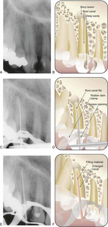
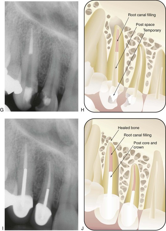
FIG. 5-1 Series of radiographs and illustrations demonstrating root canal treatment and restoration of a maxillary canine. A-B, Maxillary canine with periradicular lesion of endodontic origin. C-D, Endodontic file corresponding to length of canal; isolation with rubber dam throughout procedure. E-F, Endodontic filling material placed after cleaning and shaping of canal. G-H, Canal system filled and post space made. I-J, One-year follow-up shows completed restoration and healed periradicular bone.
What Does Root Canal Treatment Involve?
Treatment may require one to three appointments, depending on the diagnosis, the number of roots, and the complexity of the case. During these appointments the clinician removes the injured or diseased pulp tissue. The root canals are cleaned, enlarged, and sealed to prevent recontamination of the root canal system. The following steps (Fig. 5-1) describe the technical aspects of the treatment (illustrations, diagrams, radiographs, and digital images should be used as aids to the presentation):
Some additional points should be conveyed to the patient after treatment. The patient should not be given the impression that there will be no pain after the treatment.65 In most cases, the mild discomfort the patient may experience is transitory and can usually be treated with an over-the-counter antiinflammatory or analgesic agent, for example, an ibuprofen-containing compound. In fact, prophylactic administration of these drugs before the patient leaves the office will help reduce posttreatment discomfort by achieving therapeutic blood levels of analgesic before the local anesthesia wears off (see Chapter 20). In certain cases, simply handing the patient a written prescription for a stronger analgesic, “just in case,” conveys a feeling of empathy and caring toward the patient and strengthens the doctor–patient relationship.
If the clinician wishes to refer the patient to an endodontist for treatment, skillful words of encouragement and explanation will convey the caring and concern behind this recommendation. Many patients already feel comfortable with their clinicians and are fearful of seeing someone new. In addition, they may not understand why a general clinician chooses not to do the root canal treatment. The referring clinician can help by carefully explaining the complex nature of the case and why it would be in the patient’s best interests to visit the endodontist, who is specially trained to handle complex cases.65
Informed Consent
Much controversy surrounds the legal aspects of informed consent. The current thinking in the courts is that for consent to be valid, it must be freely given; that all terms must be presented in language that the patient understands; and that the consent must be “informed.”17,18,57 For consent to be informed, the following conditions must be included in the presentation to the patient:
It is probably in the best interests of the clinician–patient relationship to have the patient sign a valid informed consent form. With the continuous rise in dental litigation, it is important to realize that “no amount of documentation is too much and no amount of detail is too little.”57 (For further information on this subject, see Chapters 11 and 27.)
Radiation Safety
A critical portion of the endodontic case presentation and informed consent involves educating the patient about the requirement for radiographs as part of the treatment. The clinician must communicate to the patient that the benefits of radiographs far outweigh the risks of receiving small doses of ionizing radiation, as long as techniques and necessary precautions are properly executed.2 Although levels of radiation in endodontic radiography range from only 1/100 to 1/1000 of the levels needed to sustain injury,53,64 it is still best to keep ionizing radiation to a minimum for the protection of both the patient and the dental delivery team.
Two simple analogies can be used to help the patient understand the small risk associated with dental radiographs. A patient would have to receive 25 complete full mouth series (i.e., 450 exposures) within a very short time to significantly increase the risk of skin cancer.53 One full mouth survey (i.e., 20 Ektaspeed [E]–speed films with rectangular collimation) has been found to deliver less than one half the amount of radiation of a single chest film and less than 1% of the amount of a barium study of the intestines.70 Nevertheless, the principles of ALARA (as low as reasonably achievable), which are techniques used to reduce radiation exposure, should be followed as closely as possible to minimize the amount of radiation that both patient and treatment team receive. ALARA also implies the possibility that no matter how small the radiation dose, there still may be some deleterious effects.53,70
Principles of ALARA
In endodontic radiography, fast (i.e., sensitive) speed film should be selected.53 Although E-speed film allows for a reduction of approximately 50% of the radiation exposure required for D speed,26 findings in observer preference studies have been mixed as to the quality, clarity, and diagnostic capability of E film compared with D film. Processing of E-speed film is also more sensitive.26,27,39 Specialized radiographic systems56,70 (using direct or indirect digital intraoral radiography) involve the digitization of ionizing radiation and use considerably smaller amounts of radiation to produce an image that is available immediately after exposure (see the later section, Digital Radiographic Techniques).
Meticulous radiographic technique helps reduce the number of retakes and obviates further exposure. Film-holding devices (discussed later in the chapter) along with correct film and tube head positioning are essential to maintain film stability and produce radiographs of diagnostic quality.53,70 A quality assurance program for film processing should also be set up to ensure that films are properly processed.53,70
Dental units should be operated using at least 70 kVp (peak kilovoltage). The lower the kilovoltage, the higher the patient’s skin dose. Optimally, 90 kVp should be used. Units operating at 70 kVp or higher must have a filtration equivalent of 2.5 mm of aluminum to remove the extraneous low-energy x-rays before the patient absorbs them.53,70
Collimation also reduces exposure level. Collimation is, essentially, the restriction of the x-ray beam size by means of a lead diaphragm so that the beam does not exceed 2.75 inches (7 cm) at the patient’s skin surface. Open-ended, circular, or rectangular lead-lined cylinders, known as position-indicating devices (PIDs), help direct the beam to the target. However, the universal rectangular cylinder also collimates the x-ray beam by decreasing beam size even more, reducing the area of skin surface exposed to x-radiation and reducing radiation burden by approximately 50% (Fig. 5-2). These PIDs, or cones, should be at least 12 to 16 inches long, because the shorter (i.e., 8-in.) cones that provide shorter source-to-film distances permit more divergence of the beam and more exposure to the patient.53,70 Pointed cones, illegal in some states, should not be used because of the increased amount of scatter radiation they produce.
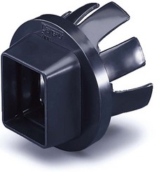
FIG. 5-2 Universal collimator snaps on the aiming ring to extend the extra protection of a rectangular collimator to round, open-ended cones.
(Courtesy DENTSPLY Rinn, Elgin, IL.)
On the basis of the December 2003 National Council on Radiation Protection and Measurements (NCRP) Report No. 145 on new dental x-ray guidelines (http://www.ncrponline.org/Publications/145press.html), leaded aprons are no longer required as long as other recommendations stated in the report are strictly followed; the report also states that thyroid collars are mandatory for children and should be provided for adults.52 When exposing films, the clinician should stand behind a barrier. Plaster, cinderblock, and at least 2.5 inches of drywall provide the necessary protection from the radiation produced by dental units. If there is no barrier the clinician should stand in an area of minimal scatter radiation: at least 6 feet away from the patient and in an area that lies between 90 and 135 degrees to the beam.53,70 All dental personnel who might be exposed to occupational x-radiation should wear film badges for recording exposure. If the concept of ALARA is strictly adhered to, no member of the dental team should receive doses close to the maximal permissible dose (MPD) (i.e., 50 millisieverts [mSv]/yr/whole body).70
For “declared” pregnant workers, the Nuclear Regulatory Commission limits the radiation dose to the fetus to 0.5 mSv during the gestation period. It is important to note that the MPD is specified as occupational exposure and should not be confused with exposure that patients receive as a result of radiographic procedures. Although no state-recommended maximal patient exposures exist, anyone who administers ionizing radiation is responsible for consulting the respective state’s bureau of radiation control to obtain information about current laws. Nonetheless, every effort should be made to keep the radiation dose to all individuals as low as possible and to avoid any unnecessary radiation exposure.
Premedication With Antibiotics
Prophylactic coverage with antibiotics or antiinfectives is indicated only for the highest risk patients who are susceptible to infective endocarditis after bacteremia. The use of prophylactic antibiotics in these patients prevents blood-borne microorganisms from lodging on shunts and prostheses or from multiplying within a depressed system.44,55,59,71 In 2007 there was a major revision of the 1997 guidelines.71 The current recommendations are based on a collective body of evidence published in numerous studies over the past two decades. Studies now indicate that infective endocarditis is more likely to result from frequent random bacteremias of routine daily activities than from an isolated dental procedure. The 2007 guidelines recommend that only patients at highest risk are to receive antibiotic prophylaxis. Those cardiac conditions associated with the highest risk of an adverse outcome from endocarditis include patients with prosthetic cardiac valves, a previous history of infective endocarditis, certain congenital heart diseases, and cardiac transplantation patients who develop cardiac valvulopathies. It is also thought that antibiotic prophylaxis prevents only a small number of cases of infective endocarditis and that the risk of antibiotic-associated adverse events may actually exceed the benefit of prophylaxis.5,66,67,71 The current recommendations of the American Heart Association (AHA, Dallas, TX) place increased emphasis on maintaining good oral hygiene in an effort to decrease the overall frequency of bacteremias that are associated with daily activities.
Conditions in the moderate-risk category include most other congenital cardiac malformations, rheumatic heart disease, hypertrophic cardiomyopathy, and mitral valve prolapse with valvular regurgitation or thickened leaflets or both. Patients with cardiac conditions in the moderate-risk category will no longer receive antibiotic prophylaxis according to the 2007 guidelines. Conditions in the negligible-risk category (i.e., no greater risk than for the general population) and for which prophylaxis is not recommended include previous coronary artery bypass graft surgery, mitral valve prolapse without valvular regurgitation, previous rheumatic fever without valvular dysfunction, and cardiac pacemakers (both intravascular and epicardial). On the basis of the recommendations in the 2007 guidelines, fewer patients will need to be covered with a prophylactic antibiotic regimen. This may raise concerns with patients who in the past have taken antibiotics for cardiac conditions and are now told that prophylaxis is no longer necessary. Therefore the clinician should be well versed in the new AHA guidelines and be prepared to discuss the revisions with inquiring patients.
The AHA has developed a standard prophylactic antibiotic regimen for patients at risk and a set of alternative regimens for those unable to take oral medications, for those who are allergic to the standard antibiotics, and for those who are not candidates for the standard regimen. The recommended standard prophylactic regimen for all dental, oral, and upper respiratory tract procedures is currently amoxicillin. This is because amoxicillin is better absorbed by the gastrointestinal tract and provides higher and more sustained serum levels than penicillin.
The major modification of the 1997 regimen was that the posttreatment dose had been eliminated; the rationale for this was that amoxicillin has a sufficiently high plasma level for an adequate time to prevent endocarditis. Erythromycin was also eliminated as a recommended drug in the penicillin-allergic patient because of the high incidence of gastrointestinal upset and the variability of the pharmokinetics of the various erythromycin preparations. The 2007 guidelines have placed less of an emphasis on invasive dental treatments as a causal factor for infective endocarditis and greater emphasis on factors associated with hygiene and oral health. The official AHA recommendations for prophylactic antibiotic regimens do not specify all clinical situations for which patients may be at risk. Thus it is the responsibility of the clinician to exercise judgment or consult the patient’s physician before giving treatment. With respect to premedication for dental patients with total joint replacements, there has been considerable controversy as to whether such patients require routine prophylaxis. In 1997 the ADA and American Academy of Orthopaedic Surgeons [AAOS, Rosemont, IL]) drafted an advisory statement4 on antimicrobial premedication for dental patients with total joint replacements. This advisory statement was followed in 2003 by another advisory statement, which essentially is in agreement with the 1997 guidelines.5 The joint organizations recognized that there was no agreed-on scientific evidence to support the contention that antibiotic prophylaxis is necessary to prevent metastatic infection in patients with total joint prostheses. They also agreed that the analogy between late prosthetic joint infections and infective endocarditis was invalid, because the anatomy, blood supply, types of microorganisms involved, and mechanisms of infection all differ. The ADA and AAOS concluded that antibiotic prophylaxis is not indicated for dental patients with pins, plates, and screws, nor is it routinely indicated for most dental patients with total joint replacements.
However, because limited evidence exists that some dental procedures are high-risk procedures (e.g., extractions, intraligamentary local anesthesia, endodontic surgery, and endodontic instrumentation “beyond the apex”) and that some medically compromised patients with total joint replacements (e.g., those with insulin-dependent diabetes; inflammatory arthropathies, such as rheumatoid arthritis; immunosuppression; hemophilia; and previous prosthetic joint infections) may be at higher risk for hematogenous infections, an antibiotic regimen should be considered. Prophylaxis should also be recommended during the first 2 years after joint replacement. The antibiotic regimen consists of cephalexin, Cefazolin, or amoxicillin (2 g per os, 1 hour before procedure). For those allergic to penicillin or cephalosporin, the recommended antibiotic is clindamycin (600 mg per os, 1 hour before procedure). It is recommended that patients who are not allergic to penicillin but who are unable to take oral medications should receive cefazolin (1 g) or ampicillin (2 g), administered intramuscularly or intravenously, 1 hour before the dental procedure. For patients allergic to penicillin and unable to take oral medications, the recommendation is clindamycin (600 mg administered intramuscularly or intravenously, 1 hour before the dental procedure). Similar to the AHA guidelines, follow-up doses are no longer recommended. The advisory statement represents only recommended guidelines and is not intended as a standard of care, because it is impossible to make recommendations for all clinical situations in which late infection might occur in total joint prostheses. Clinicians must exercise their own clinical judgment in determining whether to premedicate a patient.
Bisphosphonate-Associated Osteonecrosis of the Jaws
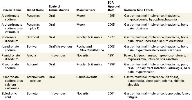
Bisphosphonates are an important class of drugs that are commonly used to reduce the morbidity associated with osteoclast-mediated bone diseases. Bisphosphonates inhibit bone resorption, improving bone densities by a reduction in bone turnover. They are extremely useful in the treatment of osteoporosis, Paget’s disease, hypercalcemia associated with certain malignancies such as multiple myeloma, and breast and prostate cancers. Bisphosphonates have a high affinity for bone and once incorporated into the skeleton can persist for many years; the estimated half-life for alendronate is known to be approximately 12 years.43 Nine bisphosphonate drugs are currently approved for clinical use by the FDA. Seven of these formulations are oral bisphosphonates, with only pamidronate and zoledronate being administered intravenously. The intravenously administered forms have higher bioavailability and potencies than the oral forms.
In 2003 case reports describing necrosis of the bones of the jaw in long-term bisphosphonate patients began appearing in the literature.10,48,50 At present, an exposed area of necrotic bone of the jaw that has been present for at least 8 weeks in a patient undergoing long-term bisphosphonate therapy, without a prior history of radiation treatment, has been defined as bisphosphonate-associated osteonecrosis of the jaw (ONJ). Most cases of ONJ have been diagnosed after a traumatic dental procedure such as a tooth extraction; however, there are also reports of spontaneous cases.51 Most cases of ONJ have been associated with the intravenously administered bisphosphonates, but there have been reports of its occurrence with oral bisphosphonates.61 Clinically, ONJ presents as a painful, soft tissue swelling and infection of the jaw, mobility of the teeth, and exposure of bone but at times the disease can be asymptomatic. Most intraoral sites affected are those areas of bone that are covered by thin and friable mucosa; especially vulnerable are the torus mandibularis and torus palatinus.72 Treatment of ONJ is problematic and at present there are no evidence-based guidelines. There have been reports of limited responses to surgical debridement, segmental resections, antibiotic therapy, and hyperbaric oxygen therapy, and therefore the emphasis must be placed on prevention. Patients taking bisphosphonates must be informed of the possibility of potential oral complications and the clinician must be vigilant in assessing the known risk factors in these patients. Preventive procedures including caries control and appropriate endodontic treatment should be considered for high-risk patients to reduce the risk of developing ONJ, as its treatment is unpredictable. A multidisciplinary approach to managing patients with ONJ is advised, with the clinician working in close association with the oncologist, oral surgeon, and other specialists. Although the overall incidence appears to be low despite the vast number of patients who take these drugs, it is important to recognize that ONJ can be a life-changing, debilitating condition for those afflicted. As our present knowledge regarding bisphosphonate-associated osteonecrosis continues to evolve, the clinician is encouraged to stay informed and up to date about this relatively new pathologic entity (Table 5-1).
Antianxiety Regimens
Because patients often have been misinformed about root canal treatment, some may understandably experience increased anxiety about undergoing the procedure. Fortunately, however, the vast majority of patients are able to tolerate their anxiety, control their behavior, and allow treatment to proceed with few problems. Appropriate behavioral approaches can be used to manage most anxious dental patients. Retrospective studies20 concerning dental anxiety have clearly demonstrated that explaining each procedure before beginning root canal treatment can effectively reduce a patient’s anxiety. The clinician can also reduce patient anxiety by giving specific information during treatment, by advising the patient about possible minor discomfort, and by explaining how that discomfort can be controlled. Verbal support, reassurance, and personal warmth also help to ease patient anxiety during root canal treatment. Many of these measures can be taken during the case presentation.
Although the clinician’s hope and desire may not cure a patient’s fear of root canal treatment, each clinician should realize that all anxious patients are not alike; therefore each patient should be managed individually. If behavioral solutions are not feasible or effective in a particular case, pharmacologic approaches to managing patient anxiety may be exercised. Selection of such pharmacotherapeutic techniques must involve a careful assessment of the relative risks and benefits of the alternative approaches. All pharmacologic treatment regimens include the need for good local anesthetic technique. For the management of mild to moderate anxiety states, these regimens range from nitrous oxide plus oxygen sedation to oral sedation to intravenous or conscious sedation (for further information on these issues, see Chapter 19 and online Chapter 26).
Pain Control by Pretreatment Administration of NSAIDs
During root canal cleaning and shaping, extrusion of small amounts of pulp tissue remnants and dentin filings is likely to occur. Often this extrusion results in additional inflammation and some posttreatment discomfort. Prophylactic administration of a nonsteroidal antiinflammatory drug (NSAID), such as 200 to 400 mg of ibuprofen 30 to 60 minutes before the procedure, has been shown to reduce or prevent posttreatment dental pain36 (see Chapter 19 for further information).
Pain Control by Local Anesthesia
It is paramount to obtain a high level of pain control when performing root canal treatment; in no other specialty is this task as challenging or as demanding. The clinician must strive for a “painless” local anesthetic injection technique, with relatively rapid onset of analgesia (see Chapter 20).
Preparation of Radiographs
Radiographs are essential to all phases of endodontic therapy. They contribute information important for the diagnosis and the various treatment phases and help evaluate the success or failure of treatment. Because root canal treatment relies on accurate radiographs, it is necessary to master radiographic techniques to achieve films of maximal diagnostic quality. Such mastery minimizes retaking of films and avoids additional exposure of patients. Expertise in radiographic interpretation is essential for recognizing deviations from the norm and for understanding the limitations associated with endodontic radiography.
Functions, Requirements, and Limitations of the Radiograph in Endodontics
The primary radiograph used in endodontics is the periapical radiograph. In diagnosis this film is used to identify abnormal conditions in the pulp and periradicular tissues. It is also used to determine the number of roots and canals, location of canals, and root curvatures. Because the radiograph is a two-dimensional image (a major limitation), it is often advantageous to expose additional radiographs at different horizontal or vertical angulations when treating multicanal and multirooted teeth. Exposing additional radiographs is also helpful when treating teeth with severe root curvature. These supplemental radiographs enhance visualization and evaluation of the three-dimensional structure of the tooth.
Technically, for endodontic purposes, a radiograph should depict the tooth in the center of the films. Consistent film placement in this manner will minimize interpretation errors, because the center of the films contains the least amount of distortion. In addition, at least 3 mm of bone must be visible beyond the apex of the tooth. Failure to capture this bony area may result in misdiagnosis, improper interpretation of the apical extent of a root, or incorrect determination of file lengths for canal cleaning and shaping. Finally, the image on the film must be as anatomically correct as possible. Image shape distortion caused by elongation or foreshortening may lead to interpretive errors during diagnosis and treatment.30,70
The bite-wing radiograph may be useful as a supplemental film. This film normally has less image distortion because of its parallel placement, and it provides critical information about the anatomic crown of the tooth. This information includes the anatomic extent of the pulp chamber, the existence of pulp stones or calcifications, recurrent caries, the depth of existing restorations, and any evidence of previous pulp therapy.65 The bite-wing also indicates the relationship of remaining tooth structure relative to the crestal height of bone. Thus it can aid in determining the restorability of the tooth.
In addition to their diagnostic value, high-quality radiographs are mandatory during the treatment phase. Technique is even more critical, however, because working radiographs must be exposed while the rubber dam system is in place. Visibility is reduced, and the bows of the clamp often restrict precise film positioning. During treatment, periradicular radiographs are used to determine canal working lengths; the location of superimposed objects, canals, and anatomic landmarks (by altering cone angulations); biomechanical instrumentation; and master cone adaptation (see Fig. 5-1, C to F). After completion of the root canal procedure, a radiograph should be exposed to determine the quality of the root canal filling or obturation. Follow-up radiographs exposed at similar angulations enhance assessment of the success or failure of treatment (see Fig. 5-1, I and J).
The astute clinician can perceive that precise radiographic interpretation is undoubtedly one of the most valuable sources of information for endodontic diagnosis and treatment, but the radiograph is only an adjunctive tool and can be misleading. Information gleaned from proper inspection of the radiograph is not always absolute and must always be integrated with information gathered from a thorough medical and dental history, clinical examination, and various pulp-testing procedures (see Chapters 1 and 4).
Use of the radiograph depends on an understanding of its limitations and its advantages. The advantages are obvious: the radiograph allows a privileged look inside the jaw. The information it furnishes is essential and cannot be obtained from any other source, and its value is not diminished by a critical appraisal of its limitations.
One major limitation of radiographs is their inability to detect bone destruction or pathosis when it is limited to the cancellous bone. Studies62 have proved that radiolucencies usually do not appear unless there is external or internal erosion of the cortical plate. This factor must be considered in evaluating teeth that become symptomatic but show no radiographic changes. In most cases, root structure anatomically approaches cortical bone and, if the plate is especially thin, radiolucent lesions may be visible before there is significant destruction of the cortical plate. Nevertheless, inflammation and resorption affecting the cortical plates must still be sufficiently extensive before a lesion can be seen on a radiograph.
Principles of Endodontic Radiography
Film Placement and Cone Angulation
For endodontic purposes, the paralleling technique produces the most accurate periradicular radiograph. Also known as the long-cone or right-angle technique, it produces improved images. The film is placed parallel to the long axis of the teeth, and the central beam is directed at right angles to the film and aligned through the root apex (Fig. 5-3, A and B). To achieve this parallel orientation it is often necessary to position the film away from the tooth, toward the middle of the oral cavity, especially when the rubber dam clamp is in position.70 The long-cone (i.e., 16 to 20 in) aiming device is used in the paralleling technique to increase the focal spot-to-object distance. This has the effect of directing only the most central and parallel rays of the beam to the film and teeth, reducing size distortion.49,53,70 This technique permits a more accurate reproduction of the tooth’s dimensions, thus enhancing a determination of the tooth’s length and relationship to surrounding anatomic structures.30 In addition, the paralleling technique reduces the possibility of superimposing the zygomatic processes over the apices of maxillary molars, which often occurs with more angulated films, such as those produced by means of the bisecting-angle technique (Fig. 5-3, C and D). If properly used, the paralleling technique will provide the clinician with films with the least distortion, minimal superimposition, and utmost clarity.
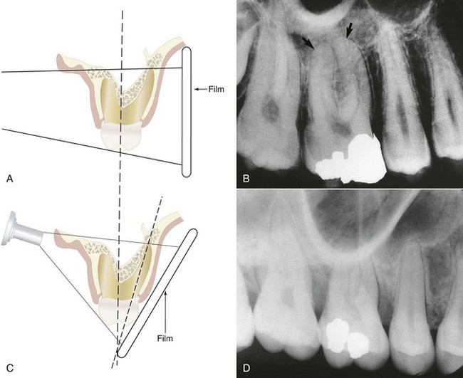
FIG. 5-3 A, Paralleling, or right-angle, technique. B, Projection of the zygomatic process above the buccal root apices by the right-angle technique, allowing visualization of the apices (arrows). C, Bisecting-angle technique. D, Superimposition of the zygomatic process over the buccal root apices of the maxillary first molar by the bisecting-angle technique.
Variations in size and shape of the oral structures (e.g., shallow palatal vault, tori, or extremely long roots) or gagging by the patient can make true parallel placement of the film impossible. To compensate for difficult placement, the film can be positioned so that it diverges as much as 20 degrees from the long axis of the tooth, with minimal longitudinal distortion. With maxillary molars, any increase in vertical angulation increases the chances of superimposing the zygomatic process over the buccal roots. A vertical angle of not more than 15 degrees should usually project the zygomatic process superiorly and away from the molar roots. To help achieve this, a modified paralleling technique19 that increases vertical angulation by 10 to 20 degrees can be used. Although this orientation introduces a small degree of foreshortening, it increases periradicular definition in this troublesome maxillary posterior region. The Snapex system (DENTSPLY Rinn, Elgin, IL), a film holder and aiming device originally designed for the bisecting-angle technique, has been altered for the modified paralleling technique.19 In conjunction with this technique, a distal angulated radiograph (i.e., a 10- to 20-degree horizontal shift of the cone from the distal, with the beam directed toward the mesial) tends to project buccal roots and the zygomatic process to the mesial, thus enhancing anatomic clarity.19
The bisecting-angle technique is not preferred for endodontic radiography. However, when a modified paralleling technique cannot be used, there may be no choice because of difficult anatomic configurations or patient management problems.19,49,53,70 The basis of this technique is to place the film directly against the teeth without deforming the film (see Fig. 5-3, C and D). The structure of the teeth, however, is such that with the film in this position, an obvious angle exists between the plane of the film and the long axis of the teeth. This causes distortion, because the tooth is not parallel to the film. If the x-ray beam is directed at a right angle to the film, the image on the film will be shorter than the actual tooth (i.e., foreshortened). If the beam is directed perpendicularly to the long axis of the teeth, the image will be much longer than the tooth (i.e., elongated). Thus, by directing the central beam perpendicular to an imaginary line that bisects the angle between tooth and film, the length of the tooth’s image on the film should be the same as the actual length of the tooth.
Although the projected length of the tooth is correct, the image will show distortion because the film and object are not parallel and the x-ray beam is not directed at right angles to both. This distortion increases along the image toward its apical extent. The technique produces additional error potential, because the clinician must imagine the line bisecting the angle (an angle that, in itself, is difficult to assess). In addition to producing more frequent superimposition of the zygomatic arch over apices of maxillary molars, the bisecting-angle technique causes greater image distortion than the paralleling technique and makes it difficult for the clinician to reproduce radiographs at similar angulations to assess healing after root canal treatment28 (see Fig. 5-3, C and D).
Film Holders and Aiming Devices
Film holders and aiming devices are required for the paralleling technique because they reduce geometric distortion caused by misorientation of the film, central beam, and tooth.19,49,53,65,70 They also minimize cone cutting, improve diagnostic quality, and allow similarly angulated radiographs to be exposed during treatment and at recall. By eliminating the patient’s finger from the x-ray field and thus the potential for displacing the film, these devices help to minimize retakes and make it easier for the patient and clinician to properly position the film.
A number of commercial devices are available that position the film parallel and at various distances from the teeth, but one of the most versatile film-holding devices is the hemostat. The clinician positions a hemostat-held film, and the handle is used to align the cone vertically and horizontally. The patient then holds the hemostat in the same position, and the cone is positioned at a 90-degree angle to the film (Fig. 5-4, A). When taking working radiographs, a radiolucent, plastic, rubber dam frame, such as an Ostby or Young frame, should be used and not removed. To position the hemostat or other film-holding device, a corner of the rubber dam is released for visibility and to allow the subsequent placement of the device-held film (Fig. 5-4, B). The Stabe disposable film holder (DENTSPLY Rinn, Elgin, IL) (Fig. 5-5) is another film-holding device that is ideal for taking pretreatment and posttreatment films.
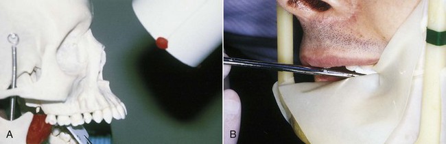
FIG. 5-4 A, With the paralleling technique, the tube head is positioned at a 90-degree angle to the film. The hemostat aids in film placement and in cone alignment. Note that the hemostat is resting on the mandibular anterior teeth so that the film is parallel with the long axis of the maxillary central incisors. B, Releasing a corner of the rubber dam aids in hemostat placement so that the film can be properly aligned.
(A, Courtesy Dr. Eddy Tidwell; B, courtesy Dr. Michelle Speier.)
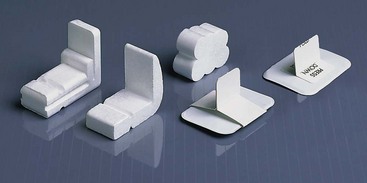
FIG. 5-5 Examples of XCP film-holding devices. Left to right, XCP Bite-Block, Stabe Bite-Block, EZ-Prop mouth prop, bite-wing loops, and adhesive bite-wing tabs.
(Courtesy DENTSPLY Rinn, Elgin, IL.)
Besides the Dunvale Snapex system mentioned earlier, the major commercial film-holding and aiming devices include the XCP (extension cone paralleling) instruments, the EndoRay II endodontic film holder, the Uni-Bite film holder, the Snap-A-Ray film holder, the Snapex system film holder with aiming device, and the Crawford film holder system (Figs. 5-6 to 5-10).
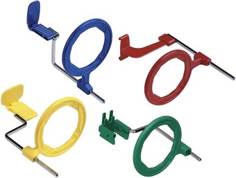
FIG. 5-6 XCP instruments hold the radiograph film packets and aid in cone alignment. Cone cutting is prevented, and consistent angulation can be achieved.
(Courtesy DENTSPLY Rinn, Elgin, IL.)
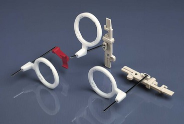
FIG. 5-7 Snapex film holder and aiming ring. The biting portion of the instrument is reduced to make it easier to place the instrument around the rubber dam.
(Courtesy DENTSPLY Rinn, Elgin, IL.)
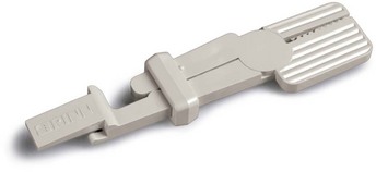
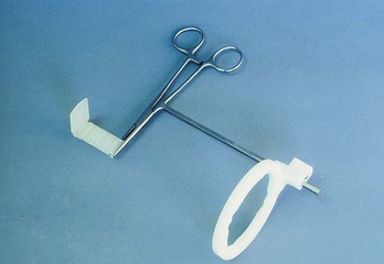
FIG. 5-9 Crawford film holder system. Components include a Kelly hemostat with aiming rod (attached), aiming ring, and bite block.
(Courtesy Dr. Frank Crawford.)
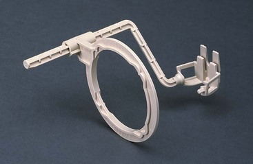
FIG. 5-10 EndoRay II: a film-holding device designed specifically for endodontic radiography. It fits over files, clamps, and dental dams without touching the subject tooth.
(Courtesy DENTSPLY Rinn, Elgin, IL.)
Variations in the use of the XCP system, for example, can prevent displacement of the rubber dam clamp and increase periradicular coverage during endodontic procedures. The film is placed off center in the bite block, and the cone is placed off center with respect to the aiming ring. This allows for placement of the bite block adjacent to the rubber dam clamp without altering the parallel relation of the cone to the film. A customized hemostat (with rubber bite block attached) can also be made to assist film placement during the taking of working radiographs. Other specialized film holders, such as the EndoRay and the Crawford film holder system, have been designed to help the clinician secure parallel working films with the rubber dam clamp in place. In general, these holders all have an x-ray beam–guiding device for a proper beam–film relationship and a modified bite block and film holder for proper positioning over or around the rubber dam clamp (see Fig. 5-10).
Exposure and Film Qualities
The intricacies of proper kilovoltage, milliamperage, and time selection serve as examples of how the diagnostic quality of a film may be altered by changes in the film’s density and contrast.53,70 Density is the degree of darkening of the film, whereas contrast is the difference between densities. The amount of darkening depends on the quantity and quality of radiation delivered to the film, the subject thickness, and the developing or processing conditions. Milliamperage controls the electron flow from cathode to anode; the greater the electron flow per unit of time, the greater will be the quantity of radiation produced. Proper density is primarily a function of milliamperage and time. Kilovoltage also affects film density by controlling the quality and penetrability of the rays. Higher kilovoltage settings produce shorter wavelengths that are more penetrating than the longer wavelengths produced at lower settings.53,70 The ability to control the penetrability of the rays by alterations in kilovoltage affects the amount of radiation reaching the film and the degree of darkening or density. Altering exposure time or milliamperage or both for each respective unit can control variations in density.53,70
Contrast is defined as the difference between shades of gray or as the difference between densities. Most variation observed in endodontic radiography occurs because of subject contrast, which depends on the thickness and density of the subject and the kilovoltage used. Thus kilovoltage is really the only exposure parameter under the clinician’s control that directly affects subject contrast.30,53,70 Exposure time and milliamperage control only the number of x-rays; therefore they influence mainly the density of the film image. A radiographic film may exhibit a long-scale, or low, contrast (i.e., more shades of gray or more useful densities); high-kilovoltage techniques (e.g., 90 kVp) produce this long scale of contrast as a result of the increased penetrating power of the rays. This results in images with many more shades of gray and less distinct differences. Films exposed at low kilovoltage settings (e.g., 60 kVp) exhibit short-scale, or high, contrast, with sharp differences between a few shades of gray, black, and white.53,70 Although they are perhaps more difficult to read, films exposed at higher kilovoltage settings (e.g., 90 kVp) make it possible to discriminate between images, often enhancing diagnostic quality; films exposed at a lower kilovoltage (e.g., 70 kVp) have better clarity and contrast between radiopaque and radiolucent structures, such as endodontic instruments near the root apex. Nevertheless, the optimal kilovoltage and exposure time should be individualized for each radiograph unit and exposure requirement.
Processing
Proper darkroom organization, film handling, and adherence to the time and temperature method of film processing play important roles in producing films of high quality.53 For the sake of expediency in the production of working films in endodontics, rapid processing methods are used to produce relatively good films in less than 1 to 2 minutes (Fig. 5-11).53,70 Although the contrast when using rapid-processing chemicals is lower than that achieved by conventional techniques, the radiographs have sufficient diagnostic quality to be used for treatment films and are obtained in less time and with less patient discomfort. Rapid-processing solutions are available commercially, but they tend to vary in shelflife, in tank life, and in the production of films of permanent quality.
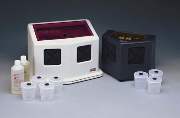
FIG. 5-11 Chairside darkroom allows rapid processing of endodontic working films.
(Courtesy DENTSPLY Rinn, Elgin, IL.)
To maintain the radiographic image for documentation, it is recommended that after an image has been evaluated it be returned to the fixer for 10 minutes more and then washed for 20 minutes and dried. An alternative is to reprocess the film by means of the conventional technique. Double film packets can also be used for working films: one can be processed rapidly and the other conventionally. Regardless of what method is used for working films, a controlled time and temperature method should be used for the diagnostic qualities desired in pretreatment, posttreatment, and recall radiographs. All radiographs taken during the course of endodontic treatment should be preserved as a part of the patient’s permanent record.
Examination and Differential Interpretation
Radiographic interpretation is not strictly the identification of a problem and the establishment of a diagnosis. The clinician must read the film carefully, with an eye toward diagnosis and treatment. Frequently overlooked are the small areas of resorption, invaginated enamel, separated files, minute fracture lines, extra canals or roots, curved and calcified canals, and, in turn, the potential problems they may create during treatment (Fig. 5-12). If a thorough radiographic examination is conducted, problems during treatment, additional time, and extra expense can be avoided or at least anticipated. As mentioned earlier, additional exposures at various angulations may be necessary to gain better insight into the three-dimensional structure of a tooth.
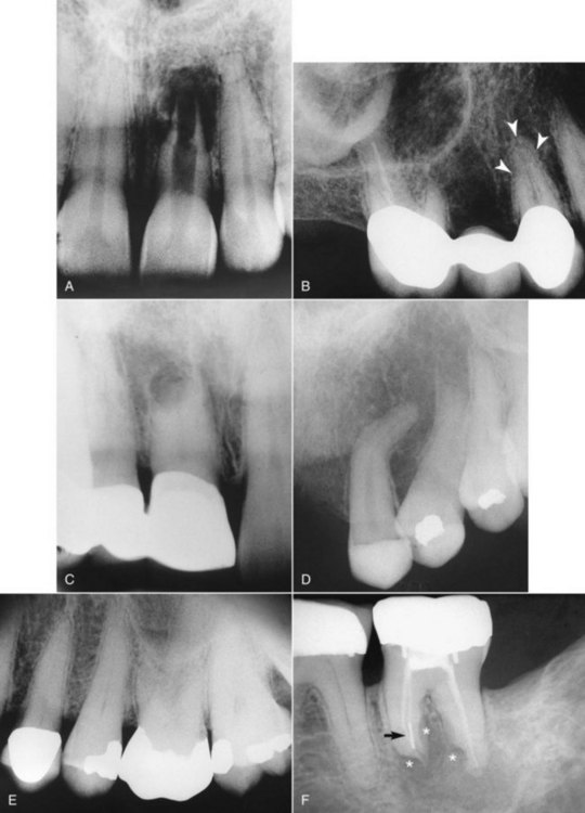
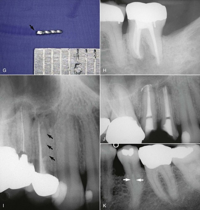
FIG. 5-12 A, Maxillary left central incisor with a history of trauma and thin walls in the apical one third of the tooth. Once an apical barrier is formed, pressures exerted during obturation could cause fracture. B, Maxillary right first premolar with three separate roots (arrows). C, Maxillary right central incisor with a history of trauma. Apical resorption and calcification of the canal system complicate treatment. D, Dilacerated root system on maxillary left canine. E, Maxillary left first molar with calcification of the chamber and root canal system. F, Endodontically treated mandibular second molar with apical root resorption (star on mesial root) and external root resorption (star on distal root); separated file in mesial root (arrow). G, Retrieved file. H, Completed retreatment. I, Angled radiograph showing evidence of another root (apical arrows) in an endodontically treated maxillary first premolar; coronal arrow indicates sealer in unprepared canal. J, Completed root canal treatment of two separate canals. K, Bifurcation (arrows) of the root canal system in a mandibular second premolar.
(H, J, and K, courtesy Dr. Francisco A. Banchs.)
Many anatomic structures and osteolytic lesions can be mistaken for periradicular pathoses. Among the more commonly misinterpreted anatomic structures are the mental foramen and the incisive foramen. These radiolucencies can be differentiated from pathologic conditions by exposures at different angulations and by pulp-testing procedures. Radiolucencies not associated with the root apex will move or be projected away from the apex by varying the angulation. Radiolucent areas resulting from sparse trabeculation can also simulate radiolucent lesions. In such cases these areas must be differentiated from the lamina dura and periodontal ligament space.
A commonly misinterpreted osteolytic lesion is periapical cemental dysplasia (“cementoma”) (Fig. 5-13). The use of pulp-testing procedures and follow-up radiographic examinations will prevent the mistake of diagnosing this as a periradicular pathosis. The development of this lesion can be monitored radiographically from its early, more radiolucent stage through its mature or more radiopaque stage.
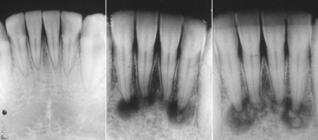
FIG. 5-13 Variations in stages of periapical cemental dysplasia (i.e., cementoma) on the four mandibular incisors. All teeth are vital.
(Courtesy Dr. Francisco A. Banchs.)
Other anatomic radiolucencies that must be differentiated from periradicular pathoses are the maxillary sinus, nutrient canals, nasal fossa, and lateral or submandibular fossa. Many systemic conditions can mimic or affect the radiographic appearance of the alveolar process. A discussion of these conditions is beyond the scope of this chapter, but the reader is encouraged to read further in any oral pathology textbook.
Lamina Dura: A Question of Integrity
One key challenge in endodontic radiographic interpretation is to understand the integrity, or lack of integrity, of the lamina dura, especially in its relationship to the health of the pulp. Anatomically, the lamina dura70 is a layer of compact bone (i.e., cribriform plate or alveolar bone proper) that lines the tooth socket. Noxious products emanating from the root canal system can effect a change in this structure that is visible radiographically. X-ray beams passing tangentially through the socket must pass through many times the width of the adjacent alveolus, and they are attenuated by this greater thickness of bone, producing the characteristic “white line.” If, for example, the beam is directed more obliquely so that it is not as attenuated, the lamina dura appears more diffuse, or it may not be discernible at all. Therefore the presence or absence and integrity of the lamina dura are determined largely by the shape and position of the root and, in turn, by its bony crypt, in relation to the x-ray beam. This explanation is consistent with the radiographic and clinical findings of teeth with normal pulps and no distinct lamina dura.62
Changes in the integrity of the periodontal ligament space, the lamina dura, and the surrounding periradicular bone certainly have diagnostic value, especially when recent radiographs are compared with previous ones. However, the significance of such changes must be tempered by a thorough understanding of the features that give rise to these images.
Buccal Object Rule (Cone Shift)
In endodontic therapy it is imperative that the clinician know the spatial or buccolingual relation of an object within the tooth or alveolus. The technique used to identify the spatial relation of an object is called the cone- or tube-shift technique. Other names for this procedure are the buccal object rule, Clark’s rule, and the SLOB (same lingual, opposite buccal) rule.31,53,60,70 Proper application of the technique allows the clinician to locate additional canals or roots, to distinguish between objects that have been superimposed, and to distinguish between various types of resorption. It also helps the clinician to determine the buccolingual position of fractures and perforative defects, to locate foreign bodies, and to locate anatomic landmarks in relation to the root apex, such as the mandibular canal.65
The buccal object rule relates to the manner in which the relative position of radiographic images of two separate objects changes when the projection angle at which the images were made is changed. The principle states that the object closest to the buccal surface appears to move in the direction opposite the movement of the cone or tube head, when compared with a second film. Objects closest to the lingual surface appear to move (on a film) in the same direction that the cone moved; thus the “same lingual, opposite buccal” rule. Figure 5-14 shows three simulated radiographs of a buccal object (yellow circle) and a lingual object (red triangle) exposed at different horizontal angles. The positions of the objects on each radiograph are compared with the reference structure (i.e., the mesial root apex of the mandibular first molar). The first radiograph (see Fig. 5-14, A and B) shows superimposition of the two objects; in this case the tube head was positioned for a straight-on view. In the second radiograph (see Fig. 5-14, C and D), the tube head was shifted mesially, and the beam was directed at the reference object from a more mesial angulation. In this case the lingual object (red triangle) moved mesially with respect to the reference object, and the buccal object (yellow circle) moved distally with respect to the reference object. In the third radiograph (see Fig. 5-14, E and F), the tube head was shifted distally and the beam was directed at the reference object from a more distal angulation; here the triangle moved distally with respect to the mesial root of the mandibular first molar, and the circle moved mesially. These radiographic relations confirm that the lingual object (red triangle) moves in the same direction with respect to reference structures as the radiograph tube and that the buccal object (yellow circle) moves in the opposite direction of the radiograph tube. Thus, according to the rule, the object farthest (i.e., most buccal) from the film moves farthest on the film with respect to a change in horizontal angulation of the radiograph cone. In an endodontically treated mandibular molar with four canals (Fig. 5-15), a straight-on view results in superimposition of the root-filled canals on the radiograph. If the cone is angled from mesial to distal, the mesiolingual and distolingual canals will move mesially and the mesiobuccal and distobuccal canals will move distally on the radiograph, when compared with the straight-on view.
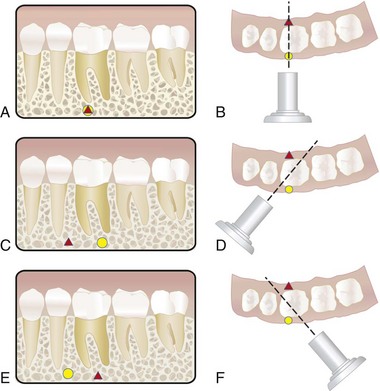
FIG. 5-14 Objects may be localized with respect to reference structures by using the buccal object rule (i.e., tube-shift technique). A-B, A straight-on view will cause superimposition of the buccal object (yellow circle) with the lingual object (red triangle). C-D, Using the tube-shift technique, the lingual object (red triangle) will appear more mesial with respect to the mesial root of the mandibular first molar, and the buccal object (yellow circle) will appear more distal on a second view projected from the mesial. E-F, The object (red triangle) on the lingual surface will appear more distal with respect to the mesial root of the mandibular first molar, and the object (yellow circle) on the buccal surface will appear more mesial on a view projected from the distal aspect.
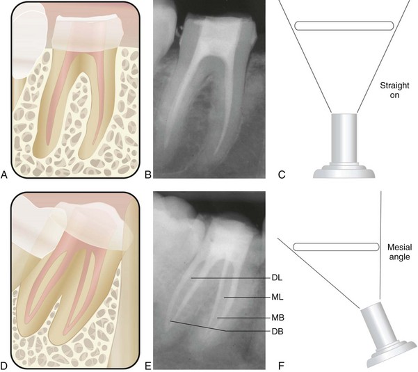
FIG. 5-15 Comparison of straight-on and mesial-angled views of an endodontically treated mandibular molar with four canals. A-C, Straight-on view of the mandibular molar shows superimposition of the root canal fillings. D-F, Mesiodistal angulation produces separation of the canals. The mesiolingual (ML) and distolingual (DL) root-filled canals move mesially (i.e., toward the cone), and the mesiobuccal (MB) and distobuccal (DB) root-filled canals move distally (i.e., away from the cone) on the radiograph.
The examples cited previously involve application of the buccal object rule, using changes in horizontal angulation. The clinician should be aware that this rule also applies to changes in vertical angulation (Fig. 5-16). To locate the position of the mandibular canal relative to mandibular molar root apices, radiographs must be taken at different vertical angulations. If the canal moves with or in the same direction as the cone head, the canal is lingual to the root apices; if the mandibular canal moves opposite the direction of the cone head, the canal is buccal to the root apices. The clinician should recognize the wide range of applicability of the buccal object rule in determining the buccolingual relationship of structures not visible in a two-dimensional image.
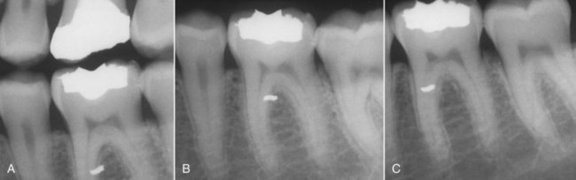
FIG. 5-16 Examples of the buccal object rule, using shifts in vertical and horizontal angulations. A, Bite-wing radiograph (straight-on view with minimal horizontal and vertical angulation) depicts amalgam particle superimposed over the mesial root of the mandibular first molar. To determine the buccolingual location of the object, the tube-shift technique (buccal object rule) must be applied. B, The periapical radiograph was exposed by shifting the vertical angulation of the cone (i.e., the radiograph beam was projected more steeply upward). Because the amalgam particle moved in the opposite direction to that of the cone (compared with the bite-wing radiograph), the amalgam particle lies on the buccal aspect of the tooth. C, The periapical radiograph was exposed by shifting the horizontal angulation of the cone. (The radiograph was exposed from a distal angle.) Compared with both A and B, each taken straight-on with minimal horizontal angulation, the amalgam particle moved opposite the direction of movement of the cone or tube head, confirming that the amalgam particle lies on the buccal aspect of the tooth.
Digital Radiographic Techniques
The replacement of traditional radiographic film with digital sensors offers many advantages to radiography. The evolution of computer technology for radiography has allowed for nearly instantaneous image acquisition, image enhancement, storage, retrieval, and even transmission of images to remote sites in a digital format. The major advantages of using digital radiography in endodontics are that radiographic images are obtained immediately and radiation exposure is reduced from 50% to 90% compared with conventional film-based radiography.56,70 The primary disadvantages of digital imaging systems are their high initial cost and potential for reduction in image quality when compared with conventional radiography.
Digital imaging systems require an electronic sensor or detector, an analog-to-digital converter, a computer, and a monitor or printer for image display.70 (See Chapters 28 and 29 online for a further discussion of digital imaging systems and how they function.)
Digitization of ionizing radiation first became a reality in the late 1980s with the development of the original RadioVisioGraphy (RVG) system by Dr. Francis Mouyen.56 This system later was marketed as the RVGui (Kodak Dental Systems/Carestream Health website, http://www.kodakdental.com/en/digital-imaging/intraoral-radiography/kodak-rvg-6100.aspx). Other available systems include Dexis digital x-ray (Dexis, Des Plaines, IL) and computed dental radiography (CDR) (Schick Technologies, Long Island City, NY) (Fig. 5-17, A and C). The FDA has approved all these systems.

FIG. 5-17 Digital imaging systems. A, Dexis digital x-ray system. B, Special shape of Dexis sensor. C, Schick desktop digital system with wireless sensor. D, Clinical placement of wireless sensor. E, Schick wired sensor covered by plastic sheath for infection control.
(A-B, Courtesy Dexis LLC, Des Plaines, IL; C-E, Courtesy Schick Technologies, Long Island City, NY.)
Direct digital systems have three components: (1) the “radio” component, (2) the “visio” component, and (3) the “graphy” component. The “radio” component consists of a high-resolution sensor with an active area that is similar in size to conventional film. However, length, width, and thickness vary slightly depending on the respective system (Fig. 5-17, B and E). The sensor is protected from x-ray degradation by a fiberoptic shield, and it can be disinfected. Specially designed multiple types of sensor holders are available; for infection control, disposable plastic sheaths are used to cover the sensor when it is in use (see Fig. 5-17, E). Wireless CDR sensors have become available through Schick Technologies. This technology provides cable-free sensors to allow enhanced mobility at chairside (see Fig. 5-17, C and D). CDR Wireless is the first wireless direct digital radiography system. Wireless sensors provide greater mobility at chairside while reportedly providing the same level of image quality acquired with conventional CDR systems. Sensors instantly transmit images directly from the mouth. The image is automatically transmitted to the computer via radio waves. Images do not need to be processed as with traditional film and storage phosphor plates. Chemical processing as with traditional film is not needed. Also, sensors do not need to be downloaded, erased, or reset between shots.
The second component of a direct digital system, the “visio” portion, consists of a video monitor and display-processing unit (see Fig. 5-17, A and C). As the image is transmitted to the processing unit, it is digitized and stored by the computer. The unit magnifies the image for immediate display on the video monitor; it also can produce colored images and display multiple images simultaneously, including a full mouth series on one screen. Because the image is digitized, further manipulation of the image is possible; this includes enhancement, contrast stretching, and reversing. A zoom feature is also available to enlarge a portion of the image up to full-screen size.
The third component of a direct digital system is the “graphy,” a high-resolution video printer that provides a hard copy of the screen image, using the same video signal. In addition, a digital intraoral camera can be integrated with most systems. Indirect digital imaging or cordless systems, such as Digora (Soredex-Finndent, Conroe, Texas) and the DenOptix digital imaging system (Gendex, Des Plaines, IL), involve the use of a reusable filmlike plate without wires. The image to be scanned by a laser (to digitize it before viewing on the computer) is recorded on this plate. Although indirect digital imaging still incorporates reduced radiation exposure and image manipulation, it usually takes slightly longer before the image can be viewed.
The advantages of both direct and indirect digital radiography seem numerous, but the primary ones include the elimination of standard radiograph film and processing chemicals, a significant reduction in exposure time (i.e., 80% to 90% reduction, when compared with D-speed film), and rapid image display. Virtually all systems can be linked with electronic record systems so that patient data can be stored, accessed, and transmitted easily. An exposure time in the range of hundredths of a second is all that is needed to generate an image.70 One study showed that digital radiographic resolution was slightly lower than that produced with silver halide film emulsions, but the radiographic information may be increased with the electronic image treatment capabilities of the system.56 These systems appear to be promising for endodontics and for the clinician.
Digital subtraction radiography58 is a sensitive method for detecting changes in radiographic density over time. In endodontics, digital subtraction radiography may be especially useful for evaluating osseous healing after treatment and as an aid in diagnosis. By definition, subtraction radiography requires that two images have nearly identical image geometry; specialized positioning devices and bite registrations aid in matching the images. The subtracted image is a composite of the images, representing their variations in density. By subtracting all anatomic structures that have not changed between radiographic examinations, changes in diagnostic information become easier to interpret. Any change is displayed on the resultant image against a neutral, gray background. Advances58 in computer technology have incorporated built-in algorithms to correct for variations in exposure and projection geometry. These advances have also enabled colorization of density changes so that hard tissue gain is represented by one color and hard tissue loss is represented by another color.
Orascopy and Endoscopy
Orascopy7 (Fig. 5-18, A), and related endoscopic instruments, have been adapted for enhanced visualization in endodontics and consist of either flexible or rigid fiberoptic endoscopes. These fiberoptic probes are available in various diameters; the probes provide a large depth of field, and refocusing is not needed after the initial focus. Once the probe is applied, the clinician views the conventional or surgical site from the magnified image displayed on the monitor. Endoscopic endodontics allows the clinician to have a nonfixed field of vision, and probes can be manipulated at various angles and distances from an object without loss of focus or image clarity. With orascopy, finite fracture lines, accessory canals, missed canals and isthmuses, and apical tissues can be viewed (Fig. 5-18, B-E). Evolving technology will likely enhance the precision and accuracy of the fiberoptic probes.
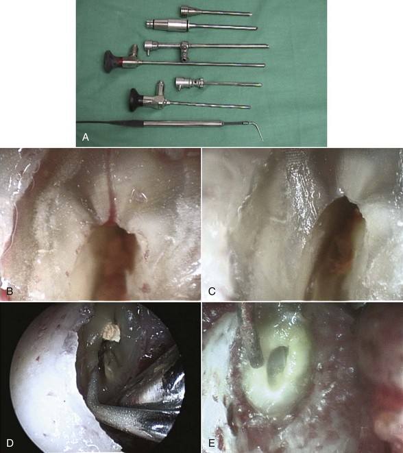
FIG. 5-18 A, Orascope instruments include various diameter probes. B, Endoscopic view of lateral canal at resected root end. C, Endoscopic view of resected root end after removal of lateral canal. D, Endoscopic view of ultrasonic preparation of isthmus and lingual canal at resected root end. E, Endoscopic view of Stropko syringe at prepared root end.
(Courtesy Dr. Barnet B. Shulman.)
Preparation for Access: Tooth Isolation
The use of the rubber dam is mandatory in root canal treatment.16,18 Developed in the nineteenth century by S.C. Barnum, the rubber dam has evolved from a system that was designed to isolate teeth for placement of gold foil to one of sophistication for the ultimate protection of both patient and clinician.65 The advantages8,12,16,29,32 and absolute necessity of the rubber dam must always take precedence over convenience and expediency (a rationale often cited by clinicians who condemn its use). When properly placed, the rubber dam facilitates treatment by isolating the tooth from obstacles (e.g., saliva and tongue) that can disrupt any procedure. Proper rubber dam placement can be done quickly and will enhance the entire procedure.
The rubber dam is used in endodontics because it ensures the following6,16,29,37,65:
The clinician should be aware that in some situations, especially in teeth with crowns, access into the pulp system may be difficult without first orienting root structure to the adjacent teeth and periodontal tissues. Radiographically, the coronal pulp system is often obscured by the restoration, and, as a result, the clinician may misdirect the bur during access. In these cases it may be necessary to locate the canal system before placing the dam. In doing so the clinician can visualize root topography, making it easier to orient the bur toward the long axis of the roots and prevent perforation. Once the root canal system is located, however, the rubber dam should be immediately placed.
Armamentarium
The mainstay of the rubber dam system is the dam itself. These autoclavable sheets of thin, flat latex come in various thicknesses (e.g., thin, medium, heavy, extraheavy, and special heavy) and in two different sizes (5 × 5 and 6 × 6 in). For endodontic purposes, the medium thickness is probably best because it tends to tear less easily, retracts soft tissues better than the thin type, and is easier to place than the heavier types. However, a thinner gauge may be desirable to decrease tension if retainer placement is questionable or if the retainer is resting on a band. The dam is also manufactured in various colors, ranging from light yellow to blue to green to gray. The darker colored dams may afford better visual contrast, thus reducing eye strain. However, the lighter colored dams, because of their translucency, have the advantage of naturally illuminating the operating field and allowing easier film placement underneath the dam. Depending on individual preference and specific conditions associated with a tooth, the clinician may find it necessary to vary the color and thickness of the rubber dam used. Glare and eyestrain can be reduced and contrast enhanced by routinely placing the dull side of the dam toward the clinician.
For patients with latex allergies, a nonlatex rubber dam is available from Coltène/Whaledent (Cuyahoga Falls, OH) (Fig. 5-19). This powder-free, synthetic dam comes in one size (6 × 6 in.) and in one thickness (medium gauge). It has a shelflife of 3 years but only one third the tensile strength of a latex dam. Other companies provide nitrile rubber dams.
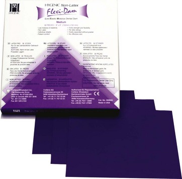
FIG. 5-19 Nonlatex dental dam is ideal for patients with known latex allergies.
(Courtesy Coltene/Whaledent, Inc., Cuyahoga Falls, Ohio.)
Another component of the rubber dam system is the rubber dam frame, which is designed to retract and stabilize the dam. Both metal and plastic frames are available, but plastic frames are recommended for endodontic procedures. They appear radiolucent, do not mask key areas on working films, and do not have to be removed before film placement. The Young Dental (Earth City, MO) rubber dam frame (plastic type), and the Nygaard-Ostby (N-O) frame (Hygenic brand; Coltène/Whaledent) are examples of radiolucent frames used in endodontics (Fig. 5-20). New to endodontics is a specially designed foldable plastic frame (Fig. 5-21), with a hinge to facilitate film or sensor placement without disengaging the entire frame. The disposable Insti-Dam (Zirc, Buffalo, MN) (Fig. 5-22) and HandiDam (Aseptico, Woodinville, WA) rubber dam systems also provide a radiolucent plastic frame. The OptraDam (Ivoclar Vivadent, Amherst, NY) is another disposable single-isolation device with a flexible outer ring, eliminating the need for an additional frame. Although metal frames (see Fig. 5-20) can be used, their radiopacity tends to block out the radiograph. If removed, this may result in destabilization of the dam and salivary contamination of the canal system, negating the disinfected environment that was previously attained.
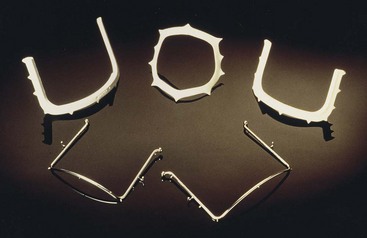
FIG. 5-20 Plastic radiolucent and metal rubber dam frames. Top left, plastic frame from Young Dental; top center, plastic Ostby frame from Coltène/Whaledent.
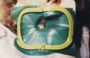
FIG. 5-21 Foldable plastic rubber dam frame (Plast-Frame) with hinge to allow for easy film/sensor placement.
(Courtesy Hager Worldwide, Odessa, FL.)
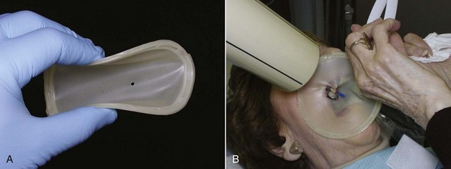
FIG. 5-22 Insti-Dam is a disposable dam system available in both latex and nonlatex. A, Bendable flexible frame allows for easy placement. B, Use of Insti-Dam during endodontic treatment.
(Courtesy Zirc, Buffalo, MN.)
Rubber dam clamps or retainers anchor the dam to the tooth requiring treatment or, in cases of multiple tooth isolation, to the most posterior tooth. They also aid in soft tissue retraction. These clamps are made of stainless steel, and each consists of a bow and two jaws. Regardless of the type of jaw configuration, the prongs of the jaws should engage at least four points on the tooth. This four-point clamp-to-tooth relationship stabilizes the retainer and prevents any rocking, which in itself can be injurious to both hard and soft tissues.38,47
Clamps are available from a variety of manufacturers and are specifically designed for all classes of teeth with a variety of anatomic configurations (Fig. 5-23). For most uncomplicated endodontic isolations, the clinician’s basic armamentarium should consist of winged clamps, a butterfly-type clamp for anterior teeth, a universal premolar clamp, a mandibular molar clamp, and a maxillary molar clamp. The wings, which are extensions of the jaws, not only provide for additional soft tissue retraction but also facilitate placement of the rubber dam, frame, and retainer as a single unit (see the next section, Methods of Rubber Dam Placement).
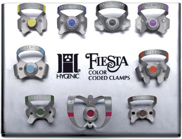
FIG. 5-23 Rubber dam clamps are color coded for ease in identification.
(Courtesy Coltène/Whaledent, Cuyahoga Falls, Ohio.)
Other retainers are designed for specific clinical situations in which clamp placement may be difficult. For example, when minimal coronal tooth structure remains, a clamp with apically inclined jaws may be used to engage tooth structure at or below the level of the free gingival margin. Retainers with serrated jaws, known as tiger clamps, also may increase stabilization of broken-down teeth. Another type of retainer, the S-G (Silker-Glickman) clamp, should also be included in the clinician’s armamentarium (Fig. 5-24). Its anterior extension allows for retraction of a dam around a severely broken-down tooth, and the clamp itself is placed on a tooth proximal to the one being treated.
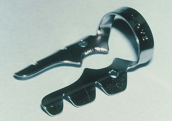
FIG. 5-24 The Silker-Glickman (S-G) clamp for isolation of severely broken-down teeth.
(Courtesy The Smile Center, Deerwood, MN.)
The remaining components of the rubber dam system include the rubber dam punch and the rubber dam forceps. The punch has a series of holes on a rotating disk from which the clinician can select according to the size of the tooth or teeth to be isolated. The forceps holds and carries the retainer during placement and removal.
Methods of Rubber Dam Placement
As mentioned earlier, an expedient method of dam placement is to position the bow of the clamp through the hole in the dam and place the rubber over the wings of the clamp (a winged clamp is required). The forceps stretch the clamp to maintain the position of the clamp in the dam, and the dam is attached to the plastic frame, allowing for the placement of the dam, clamp, and frame in one motion (Fig. 5-25). Once the clamp is secured on the tooth, the dam is teased under the wings of the clamp with a plastic instrument.
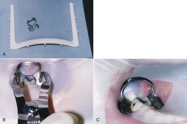
FIG. 5-25 A, Rubber dam, clamp, and frame. B, Dam, clamp, and frame carried to mouth as one unit and placed over the tooth. C, Clamp in place with four-point contact and rubber tucked under the wings.
Another method is to place the clamp, usually wingless, on the tooth and then stretch the dam over the clamped tooth (Fig. 5-26).29,56 This method offers the advantage of enabling the clinician to see exactly where the jaws of the clamp engage the tooth, thus avoiding possible impingement on the gingival tissues. Gentle finger pressure on the buccal and lingual apron of the clamp before the dam is placed can be used to test how securely the clamp fits. Variations of this method include placing the clamp and dam first, followed by the frame, or placing the rubber dam first, followed by the clamp and then the frame.65
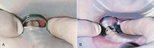
FIG. 5-26 A, After the clamp is placed, the dam is attached to the frame and gently stretched over the clamped tooth with the index finger of each hand. B, The clamp is tested for a secure fit with gentle finger pressure (alternately) on the buccal and lingual aspects of the clamp apron.
A third method, the split-dam technique, may be used to isolate anterior teeth without using a rubber dam clamp. Not only is this technique useful when there is insufficient crown structure, as in the case of horizontal fractures, but also it prevents the possibility of the jaws of the clamp chipping the margins of teeth restored with porcelain crowns or laminates. Studies38,47 on the effects of retainers on porcelain-fused-to-metal restorations and tooth structure itself have demonstrated that there can be significant damage to cervical porcelain, as well as to dentin and cementum, even when the clamp is properly stabilized. Thus for teeth with porcelain restorations, ligation with dental floss is recommended as an alternative method to retract the dam and tissues, or the adjacent tooth can be clamped.
In the split-dam method (Fig. 5-27), two overlapping holes are punched in the dam. A cotton roll is placed under the lip in the mucobuccal fold over the tooth to be treated. The rubber dam is stretched over the tooth to be treated and over one adjacent tooth on each side. The edge of the dam is carefully teased through the contacts on the distal sides of the two adjacent teeth. Dental floss helps carry the dam down around the gingiva. The tension produced by the stretched dam, aided by the rubber dam frame, secures the dam in place. The tight fit and the cotton roll help produce a relatively dry field. If the dam has a tendency to slip, a premolar clamp may be used on a tooth distal to the three isolated teeth or even on an adjacent tooth (see Fig. 5-27, A). The clamp is placed over the rubber dam, which then acts as a cushion against the jaws of the clamp.
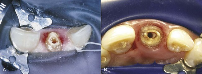
FIG. 5-27 Split-dam technique. A, Premolar clamp on maxillary central incisor along with ligation on the maxillary canine prevents dam slippage and aids in dam retraction during endodontic treatment on broken-down maxillary lateral incisor. B, Split dam used during post removal and retreatment of a maxillary central incisor.
(A, Courtesy Dr. James L. Gutmann; B, courtesy Dr. Francisco A. Banchs.)
Aids in Rubber Dam Placement
Punching and Positioning of Holes
The rubber dam may be divided into four equal quadrants, and the proper place for the hole is estimated according to which tooth is undergoing treatment. The more distal the tooth, the closer to the center of the dam the hole is placed. This method becomes easier as the clinician gains experience. The hole must be punched cleanly, without tags or tears. If the dam is torn, it may leak or permit continued tearing when stretched over the clamp and tooth.
Orientation of the Dam and Bunching
The rubber dam must be attached to the frame with enough tension to retract soft tissues and prevent bunching, without tearing the dam or displacing the clamp. The rubber dam should completely cover the patient’s mouth without infringing on the patient’s nose or eyes. To prevent bunching of the dam in the occlusal embrasure, only the edge of the interseptal portion of the dam is teased between the teeth. Dental floss is then used to carry the dam through the contacts. These contacts should always be tested with dental floss before the dam is placed. A plastic instrument is used to invert the edge of the dam around the tooth to provide a seal.
Problem Solving in Tooth Isolation
Leakage
The best way to prevent seepage through the rubber dam is meticulous placement of the entire system. Proper selection and placement of the clamp; sharply punched, correctly positioned holes; use of a dam of adequate thickness; and inversion of the dam around the tooth all help reduce leakage through the dam and into the root canal system.6,37,46,65 Nevertheless, there may be clinical situations in which small tears, holes, or continuous minor leaks may occur. These often can be patched or blocked with Cavit (3M), OraSeal caulking (UltraDent Products, South Jordan, UT), rubber base adhesive,9 “liquid” rubber dam, or periodontal packing. If leakage continues, the dam should be replaced with a new one.
Because salivary secretions can seep through even a well-placed rubber dam, persons who salivate excessively may require premedication to reduce saliva flow to a manageable level. Failure to control salivation may result in salivary contamination of the canal system and pooling of saliva beneath the dam, as well as drooling and possible choking. Such occurrences can disrupt treatment and should be prevented. Excessive saliva flow can be reduced with an anticholinergic drug, such as atropine sulfate, propantheline bromide (Pro-Banthine), methantheline (Banthine), or glycopyrrolate (Robinul).34 Therapeutic doses of atropine sulfate for adults range from 0.3 to 1 mg per os, 1 to 2 hours before the procedure. The synthetic anticholinergic drug propantheline bromide reportedly has fewer side effects than methantheline.34 The usual adult dose of propantheline bromide for an adult is 7.5 to 15 mg, taken orally 30 to 45 minutes before the appointment. Because anticholinergics can cause undesirable autonomic effects, especially through various drug interactions, they should be used only in specific cases and only as a last resort.
Unusual Tooth Shapes or Positions That Cause Inadequate Clamp Placement
Some teeth do not conform to the variety of clamps available. These include partially erupted teeth, teeth prepared for crowns, and teeth fractured or broken down to the extent that their margins are subgingival. To handle these cases, rubber dam retainers may be customized by modifying the jaws to adapt to a particular tooth (Fig. 5-28).69 In partially erupted teeth or cone-shaped teeth, such as those prepared for full coverage, one technique68 is to place spots of self-curing resin on the cervical surface of the tooth. These resin beads act as a scaffold for the retainer during treatment. Another method32 is to place small acid-etched composite lips on the teeth; these resin lips serve as artificial undercuts and remain on the teeth between appointments. When the root canal treatment is complete, the resin beads are easily removed. In multiple-treatment cases involving misshapen teeth, a customized acrylic retainer63 can be used in conjunction with a dam to isolate the operating field.
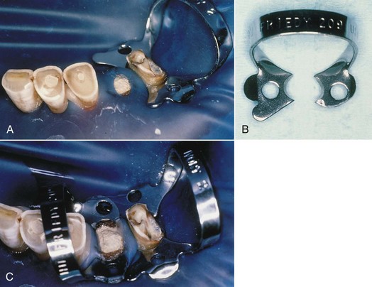
Loss of Tooth Structure
If insufficient tooth structure prevents the placement of a clamp, the clinician must first determine whether the tooth is periodontally sound and restorable. Meticulous and thorough treatment planning often can prevent embarrassing situations for both the doctor and patient. One example is the case in which the endodontic treatment is completed before restorability is determined; it is then discovered that the tooth cannot be restored.
Once a tooth is deemed restorable but the margin of sound tooth structure is subgingival, a number of methods should be considered. As mentioned earlier, less invasive methods, such as using a clamp with prongs inclined apically or using an S-G clamp, should be attempted first (see Fig. 5-24). If neither of these techniques effectively isolates the tooth, the clinician may consider clamping of the attached gingiva and alveolar process. In this situation it is imperative that profound soft tissue anesthesia exists before clamp placement. Although the procedure may cause some minor posttreatment discomfort, the periodontal tissues recover quickly with minimal posttreatment care.
Restorative Procedures
If none of the techniques mentioned previously is desirable, a variety of restorative methods may be considered to build up the tooth so that a retainer can be placed properly.45,46,65 A preformed copper band, a temporary crown, or an orthodontic band (Figs. 5-29 and 5-30) may be cemented over the remaining natural crown. This band or crown not only enables the clamp to be retained successfully but also serves as a seal for the retention of intracanal medicaments and the temporary filling between appointments, if more than one appointment is necessary. These temporary bands or crowns have several disadvantages. One of their main problems is their inability to provide a superior seal. Another concern is that particles of these soft metals or cement can block canal systems during access opening and instrumentation. Third, these temporary crowns and bands, if they become displaced or are not properly contoured, can cause periodontal inflammation.
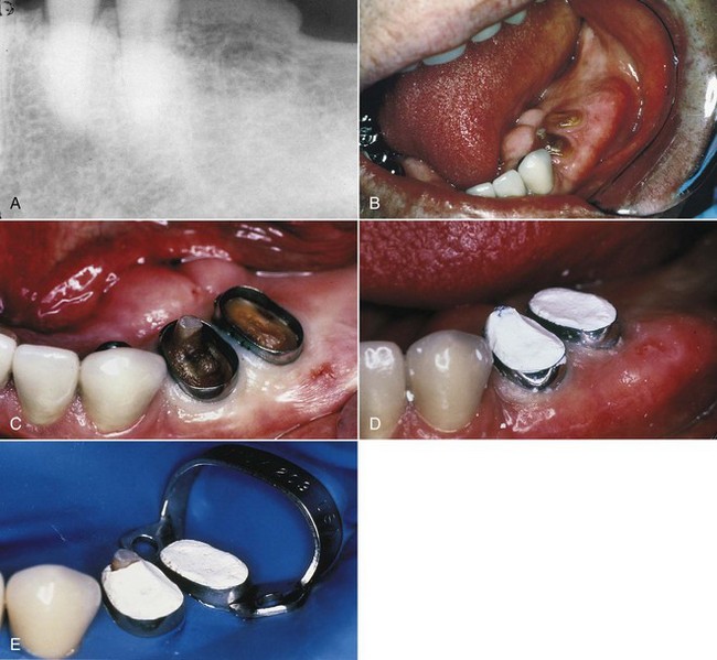
FIG. 5-29 A, Pretreatment radiograph of mandibular premolar region depicts limited supracrestal tooth structure. B, Bony exostoses and minimal tooth structure make it a difficult case for tooth isolation. C, Fitted orthodontic bands on mandibular premolars. D, Orthodontic bands cemented in place with IRM (i.e., reinforced zinc oxide–eugenol cement; DENTSPLY International [York, Penn]). E, Effective isolation with rubber dam clamp placed on distal tooth.
(Courtesy Dr. Robert Roda.)
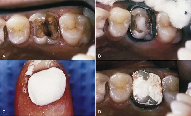
FIG. 5-30 A, Broken-down maxillary molar after removal of restoration, post, and caries. B, Fitted orthodontic band; cotton in access opening to protect orifices. C, IRM loaded into band before cementation. D, Completed temporary restoration before rubber dam placement.
(Courtesy Dr. Robert Roda.)
On occasion, so little tooth structure remains that even band or crown placement is not possible. In these cases it becomes necessary to replace the missing tooth structure to facilitate placement of the rubber dam clamp and prevent leakage into the pulp cavity during the course of treatment.45,46,65 Replacement of missing tooth structure can be accomplished with composite resins; glass ionomer cements, such as Ketac-Silver (3M, St. Paul, MN), Fuji II (GC America, Alsip, IL) (Fig. 5-31), or Photac-Fil (3M); or dentin-bonding systems, such as Adper Scotchbond (3M), the Tenure bonding system (Den-Mat, Santa Maria, CA), Gluma (Heraeus Kulzer, South Bend, IN), OptiBond (Kerr, Orange, CA), PermaQuik (UltraDent Products, South Jordan, UT), or C&B-Metabond (Parkell, Edgewood, NY).65 Although these newer dentin-bonding systems form a strong, immediate bond and are generally simple to use, any restorative method for building up a broken-down tooth is time-consuming, can impede endodontic procedures, and may duplicate restorative treatment. Many restorations that have been hollowed out by access cavities are weakened and require redoing.
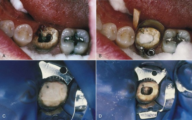
FIG. 5-31 A, Broken-down mandibular molar after crown and caries removal; preexisting pin will aid retention of restorative material. B, Isolation with wedged Automatrix. C, Completed temporary restoration using glass ionomer cement (Fuji II). D, Access through completed restoration after rubber dam placement.
(Courtesy Dr. Robert Roda.)
Canal Projection
Canal projection is a technique that facilitates preendodontic buildup of broken-down coronal and radicular structure while preserving individualized access to the canal.42 Although any of a number of syringeable materials (glass ionomer cements, temporary cements, permanent cements, etc.) and even “packable” composites may be used to project the canals, bonded injectable autopolymerizing composites have proven to be the most versatile and reliable buildup material for this technique (Fig. 5-32). The advantages of the technique are numerous:
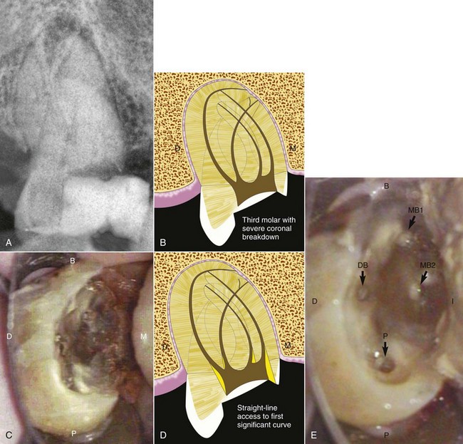
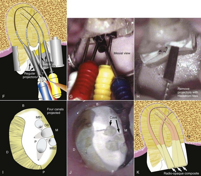
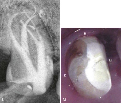
FIG. 5-32 Canal projection technique. A-C, In a tooth with severe coronal breakdown, after gaining access and locating all canals, it is essential to perform a thorough high-magnification examination of the floor and walls and to examine, as deeply as possible, all canals to ensure that all branchings and other possible irregularities have been identified before proceeding. D, In curved canals, straight-line access is created to the first significant curvature by removing dentin “triangles” with small, slow-speed round burs, working into the bulk of each root (i.e., working away from the furcal aspect of the root). E, If there is no significant curvature in a particular canal, then the orifice should be dimpled to the depth of a #2 slow-speed round bur. An appropriate matrix barrier is applied, and all bondable surfaces are etched and primed. Files are selected that will fit well into the body of each canal, and projectors (CJM Engineering, Santa Barbara, CA), tapered plastic sleeves available in various dimensions, are placed onto the files. The files are then inserted into the canals, and the projectors are slid apically until they are drawn into the seat of the previously prepared straight-line access or dimples. F-G, In this particular example, regular projectors were used in the D and P canals and skinny projectors were used in the MB1 and MB2 canals to accommodate their proximity to each other. With the canals occupied by the files and projectors, autopolymerizing bonding agent is applied and distributed over all primed surfaces with a blast of air. Autopolymerizing composite buildup material is then injected from the chamber floor to the cavosurface of the access cavity. On early signs of polymerization, the files are removed, leaving the projectors embedded in the buildup material. A bull-nosed diamond is used to contour the composite and to flatten the occlusal surface along with the embedded projectors. Leaving the projectors embedded at this stage prevents composite debris from collecting in the projected canals. H, The projectors are removed by engaging a #60 Hedström file in the lumen of each projector and withdrawing. The external surfaces of projectors are treated with a releasing agent that provides for reliable removal from all types of buildup material. I, Depending on how the projectors are arranged relative to each other as they traverse from the chamber floor through the access cavity to the occlusal surface, the projected orifices will lie in various configurations on the occlusal surface. This procedure creates durable endodontic reference points. J, If a second treatment visit is required, the projected canals may be conveniently sealed by snipping 2 mm from the large-diameter end of the projectors, reinserting them into their respective canals, and sealing with Cavit. On the patient’s return, the Cavit seals are removed with a #6 slow-speed round bur, a #60 Hedström file is again engaged in the lumen of each projector, and the projectors are withdrawn, leaving the canals free of temporary filling debris. K, After cleaning, shaping, and obturation, the projected portions of the canals are “dressed” with a high-speed football diamond to remove residual sealer and to freshen the composite, making it receptive to the final composite that is injected directly over gutta-percha from the subchamber level to the cavosurface of each projected canal. L, Selecting a composite for this final step that is more radiopaque than the buildup composite creates a unique radiographic appearance showing the canal continuously flowing from the root end to the occlusal surface. M, Crown preparation can proceed immediately. A post can be easily placed through the projection buildup at the completion of endodontic therapy. Using either a high-speed football diamond or a slow-speed #8 round bur, the projected portion of the canal to receive the post is enlarged to the level of the chamber floor. According to the particular type of post to be placed, the radicular aspect of the canal is prepared in the typical fashion, and the post is cemented or bonded into the canal. The coronal portion of the post should be surrounded by syringeable composite, effectively anchoring the buildup to the natural tooth structure. D, Distal; M, mesial; B, buccal; P, palatal; DB, distobuccal; MB1, main mesiobuccal canal; MB2, second mesiobuccal canal.
(Courtesy Dr. C. John Munce.)
Periodontal Procedures
As a result of excessive crown destruction or incomplete eruption, the presence of gingival tissue may preclude the use of a clamp without severe gingival impingement. Various techniques of gingivectomy (Fig. 5-33) or electrosurgery have been suggested for cases in which the remaining tooth structure still lies above the crestal bone. With an inadequate zone of attached gingiva, osseous defects, or a poor anatomic form, an apically positioned flap with a reverse bevel incision is the technique of choice to “lengthen” the crown.45,46
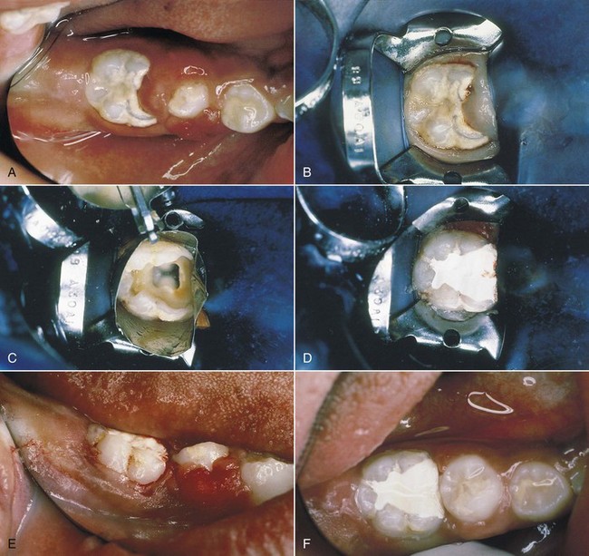
FIG. 5-33 A, Gingival hypertrophy on mandibular molar and erupting premolar of a young patient; mandibular molar requires root canal treatment. B, Rubber dam clamp impinging on gingival tissues; tissue removed with scalpel. C, Automatrix placed immediately after tissue removal; bleeding was minimal. D, Placement of IRM temporary restoration after pulpectomy. E, Posttreatment facial view immediately after gingivectomy; note hemostasis. F, Six-week posttreatment occlusal view exhibits fully exposed mandibular molar and recently erupted premolar.
(Courtesy Dr. Robert Roda.)
Electrosurgery and the conventional gingivectomy are crown-lengthening procedures for teeth that have sufficient attached gingiva and no infrabony involvement.45,46 The electrosurgery method offers the advantage of leaving a virtually bloodless site for immediate rubber dam placement. Electrosurgery units have become highly sophisticated and are capable of providing both cutting and coagulating currents that, when used properly, will not cause cellular coagulation. The wide variety of sizes and shapes of surgical electrodes enables the clinician to reach areas inaccessible to the scalpel. Further, electrosurgery facilitates the removal of unwanted tissue in such a manner as to recreate normal gingival architecture. This feature, combined with controlled hemostasis, makes the instrument extremely useful in the preparation of some teeth for placement of the rubber dam clamp.
The main drawback of electrosurgery is the potential for damage to the adjacent tissues; if the electrode contacts bone, significant destruction of bone can occur. As a result this technique is not recommended when the distance between the crestal level of bone and the remaining tooth structure is minimal. Compared with electrosurgery, conventional gingivectomy presents the major problem of hemorrhage after the procedure; this forces delay of endodontic treatment until tissues have healed.
The apically positioned flap45,46 is a crown-lengthening technique for teeth with inadequate attached gingiva, infrabony pockets, or remaining tooth structure below the level of crestal bone. With this technique as well, endodontic treatment should be delayed until sufficient healing has occurred.
Orthodontic Procedures
The most common indication for orthodontic extrusion is a fracture of the anterior tooth margin below the crestal bone.45,46 The clinician should be aware that, because bone and soft tissue attachments follow the tooth during extrusion, crown-lengthening procedures after extrusion are often necessary to achieve the desired clinical crown length and restore the biologic and aesthetic tissue relationships. Ultimately, the purpose of orthodontic extrusion is to erupt the tooth to provide 2 to 3 mm of root length above crestal bone level.
Summary
Success in endodontic therapy is predicated on a host of factors, many of which are controllable before the clinician ever initiates treatment. Proper and thorough preparation of both patient and tooth for endodontic treatment should lay the groundwork for a relatively trouble-free experience that will increase the chances for the ultimate success of the entire treatment.
1. American Association of Endodontists. Endodontics: Your guide to endodontic treatment. Chicago: American Association of Endodontists; 1996.
2. American Dental Association. OSHA: What You Must Know. Chicago: American Dental Association; 1992.
3. American Dental Association. Statement Regarding Dental Handpieces. Chicago: American Dental Association; 1992.
4. American Dental Association, American Academy of Orthopaedic Surgeons. Advisory statement: antibiotic prophylaxis for dental patients with total joint replacements. J Am Dent Assoc. 1997;128:1004.
5. American Dental Association, American Academy of Orthopaedic Surgeons. Antibiotic prophylaxis for dental patients with total joint replacements. J Am Dent Assoc. 2003;134(7):895-899.
6. Antrim DD. Endodontics and the rubber dam: a review of techniques. J Acad Gen Dent. 1983;31:294.
7. Bahcall JK, DiFiore PM, Poulakidas TK. An endoscopic technique for endodontic surgery. J Endod. 1999;25:132.
8. Baumgartner JC, Heggers JP, Harrison JW. The incidence of bacteremias related to endodontic procedures. I. Nonsurgical endodontics. J Endod. 1976;2:135.
9. Bramwell JD, Hicks ML. Solving isolation problems with rubber base adhesive. J Endod. 1986;12:363.
10. Carter GD, Goss AN. Bisphosphonates and avascular necrosis of the jaws. Aust Dent J. 2003;48(4):268.
11. Centers for Disease Control. Guidelines for preventing the transmission of Mycobacterium tuberculosis in health care facilities. Fed Regist. 1994;59:54242-54303.
12. Centers for Disease Control. Recommendations for preventing transmission of human immunodeficiency virus and hepatitis B virus to patients during exposure-prone invasive procedures. MMWR Recomm Rep. 1991;40(RR-8):1-9.
13. Centers for Disease Control. Recommendations for prevention of HIV transmission in health care settings. MMWR Morb Mortal Wkly Rep. 1987;36(Suppl 2):1S-18S.
14. Centers for Disease Control. Recommended infection control practices for dentistry. MMWR Morb Mortal Wkly Rep. 1986;35:237-242.
15. Centers for Disease Control and Prevention. Guidelines for infection control in dental health-care settings—2003. MMWR Recomm Rep. 2003;52(RR-17):1-61.
16. Cochran MA, Miller CH, Sheldrake MA. The efficacy of the rubber dam as a barrier to the spread of microorganisms during dental treatment. J Am Dent Assoc. 1989;119:141.
17. Cohen S. Endodontics and litigation: an American perspective. Int Dent J. 1989;39:13.
18. Cohen S, Schwartz SF. Endodontic complications and the law. J Endod. 1987;13:191.
19. Cohn SA. Endodontic radiography: principles and clinical techniques. Gilberts, IL: Dunvale Corp; 1988.
20. Corah NL, Gale EN, Illig SJ. Assessment of a dental anxiety scale. J Am Dent Assoc. 1978;97:816.
21. Cottone JA, Terezhalmy GT, Molinari JA. Practical Infection Control in Dentistry, ed 2. Baltimore: Williams & Wilkins; 1996.
22. Council on Dental Materials, Instruments, and Equipment; Council on Dental Practice; Council on Dental Therapeutics. Infection control recommendations for the dental office and the dental laboratory. J Am Dent Assoc. 1988;116:241.
23. Dajani AS, Taubert KA, Wilson W, et al. Prevention of bacterial endocarditis: recommendations by the American Heart Association. JAMA. 1997;277:1794.
24. Daneshkazemi AR. Resistance of bonded composite restorations to fracture of endodontically treated teeth. J Contemp Dent Pract. 2004;5:51.
25. Department of Labor, Occupational Safety and Health Administration. Occupational exposure to bloodborne pathogens, final rule. Fed Regist. 1991;56(235):64004.
26. Donnelly JC, Hartwell GR, Johnson WB. Clinical evaluation of Ektaspeed x-ray film for use in endodontics. J Endod. 1985;11:90.
27. Farman AG, Mendel RW, von Fraunhofer JA. Ultraspeed versus Ektaspeed x-ray film: endodontists’ perceptions. Oral Surg Oral Med Oral Pathol Oral Radiol Endod. 1995;79:756.
28. Ford TR, Torabinejad M, McKendry DJ, Hong CU, Kariyawasam SP. Use of mineral trioxide aggregate for repair of furcal perforations. In: Your Guide to Endodontic Treatment. Chicago: American Association of Endodontists; 1996.
29. Forrest W, Perez RS. The rubber dam as a surgical drape: protection against AIDS and hepatitis. J Acad Gen Dent. 1989;37:236.
30. Forsberg J. Radiographic reproduction of endodontic “working length” comparing the paralleling and bisecting-angle techniques. J Oral Surg. 1987;64:353.
31. Goerig AC, Neaverth EJ. A simplified look at the buccal object rule in endodontics. J Endod. 1987;13:570.
32. Greene RR, Sikora FA, House JE. Rubber dam application to crownless and cone-shaped teeth. J Endod. 1984;10:82.
33. Hess CG Physician as an employer Legal Medicine ed 6 2004 Mosby Philadelphia
34. Holroyd SV, Wynn RL, Requa-Clark B. Clinical Pharmacology in Dental Practice, ed 4. St. Louis: Mosby; 1988.
35. Hürmüzlü F, Kiremitçi A, Serper A, Altundaşar E, Siso SH. Fracture resistance of endodontically treated premolars restored with Ormocer and packable composite. J Endod. 2003;29:838.
36. Jackson DJ, Moore PA, Hargreaves KM. Preoperative nonsteroidal anti-inflammatory medication for the prevention of postoperative dental pain. J Am Dent Assoc. 1989;119:641.
37. Janus CE. The rubber dam reviewed. Compend Contin Educ Dent. 1984;5:155.
38. Jeffrey IWM, Woolford MJ. An investigation of possible iatrogenic damage caused by metal rubber dam clamps. Int Endod J. 1989;22:85.
39. Kantor ML, et al. Efficacy of dental radiographic practices: options for image receptors, examination selection, and patient selection. J Am Dent Assoc. 1989;119:259.
40. Kelly WH. Radiographic asepsis in endodontic practice. J Acad Gen Dent. 1989;37:302.
41. Kolstad RA. Biohazard control in dentistry. Dallas: Baylor College of Dentistry Press; 1993.
42. Kurtzman GM. Restoring teeth with severe coronal breakdown as a prelude to endodontic therapy. Endod Ther. 2004;4(1):21.
43. Lin JH, Russell G, Gertz B. Pharmacokinetics of alendronate: an overview. Int J Clin Pract Suppl. 1999;101:18-26.
44. Little JW, Falace DA, Miller CS, Rhodus NL. Dental management of the medically compromised patient, ed 7. St. Louis: Mosby; 2008.
45. Lovdahl PE, Gutmann JL. Periodontal and restorative considerations prior to endodontic therapy. J Acad Gen Dent. 1980;28:38.
46. Lovdahl PE, Wade CK. Problems in tooth isolation and periodontal support for the endodontically compromised tooth. In Gutmann JL, et al, editors: Problem-solving in Endodontics: Prevention, Identification, and Management, ed 3, St. Louis: Mosby, 1997.
47. Madison S, Jordan RD, Krell KV. The effects of rubber dam retainers on porcelain-fused-to-metal restorations. J Endod. 1986;12:183.
48. Marx RE. Pamidronate (Aredia) and zoledronate (Zometa) induced avascular necrosis of the jaws: a growing epidemic. J Oral Maxillofac Surg. 2003;61(9):1115-1117.
49. Messing JJ, Stock CJR. Color Atlas of Endodontics. St. Louis: Mosby; 1988.
50. Migliorati CA. Bisphosphonates and oral cavity avascular bone necrosis. J Clin Oncol. 2003;21(22):4253-4254.
51. Migliorati CA, Schubert MM, Peterson DE, Seneda LM. Bisphosphonate-associated osteonecrosis of mandibular and maxillary bone: an emerging oral complication of supportive cancer therapy. Cancer. 2005;104(1):83-93.
52. Miles DA, Langlais RP. National Council on Radiation Protection and Measurement. New dental X-ray guidelines: their potential impact on your dental practice. NCRP report no. 145. Dentistry Today. 2004;23(9):128.
53. Miles DA, Van Dis ML, Williamson GF, et al. Radiographic imaging for the dental team, ed 4. St. Louis: Saunders; 2009.
54. Miller CH. Infection control. Dent Clin North Am. 1996;40:437.
55. Montgomery EH, Kroeger DC. Principles of anti-infective therapy. Dent Clin North Am. 1984;28:423.
56. Mouyen F, Benz C, Sonnabend E, et al. Presentation and physical evaluation of RadioVisioGraphy. Oral Surg Oral Med Oral Pathol. 1989;68:238.
57. Pollack BR, editor. Handbook of dental jurisprudence and risk management. Littleton, MA: PSG Publishing Co, 1987.
58. Reddy MS, Jeffcoat MK. Digital subtraction radiography. Dent Clin North Am. 1993;37:553.
59. Requa-Clark B, Holroyd SV. Antiinfective agents. In Holroyd SV, Wynn RL, Requa-Clark B, editors: Clinical Pharmacology in Dental Practice, ed 4, St. Louis: Mosby, 1988.
60. Richards AG. The buccal object rule. Dent Radiogr Photogr. 1980;53:37.
61. Ruggiero SL, Mehrotra B, Rosenberg TJ, Engroff SL. Osteonecrosis of the jaws associated with the use of bisphosphonates: a review of 63 cases. J Oral Maxillofac Surg. 2004;62(5):527-534.
62. Schwartz SF, Foster JK. Roentgenographic interpretation of experimentally produced boney lesions. I. Oral Surg Oral Med Oral Pathol. 1971;32:606.
63. Teplitsky PE. Custom acrylic retainer for endodontic isolation. J Endod. 1988;14:150.
64. Torabinejad M, et al. Absorbed radiation by various tissues during simulated endodontic radiography. J Endod. 1989;15:249.
65. Torabinejad M, Walton RE. Principles and practice of endodontics, ed 4. Philadelphia: Saunders; 2009.
66. Van der Meer JT, Thompson J, Vandengroucke JP, Valkenburg HA, Michel MF. Efficacy of antibiotic prophylaxis for prevention of native-valve endocarditis. Lancet. 1999;339(8786):135-139.
67. Van der Meer JT, Thompson J, Valkenburg HA, Michel MF. Epidemiology of bacterial endocarditis in The Netherlands. II. Antecedent procedures and use of prophylaxis. Arch Intern Med. 1992;152(9):1869-1873.
68. Wakabayashi H, Ochi K, Tachibana H, et al. A clinical technique for the retention of a rubber dam clamp. J Endod. 1986;12:422.
69. Weisman M. A modification of the no. 3 rubber dam clamp. J Endod. 1983;9:30.
70. White SC, Pharoah MJ. Oral Radiology: Principles and Interpretation, ed 6. St. Louis: Mosby; 2009.
71. Wilson W, Taubert KA, Gerwitz M, et al. Prevention of infective endocarditis: guidelines from the American Heart Association: a guideline from the American Heart Association Rheumatic Fever, Endocarditis and Kawasaki Disease Committee, Council on Cardiovascular Disease in the Young, and the Council on Clinical Cardiology, Council on Cardiovascular Surgery and Anesthesia, and the Quality of Care and Outcomes Research Interdisciplinary Working Group. J Am Dent Assoc. 2008;139(Suppl):3S-24S.
72. Woo SB, Hellstein JW, Kalmar JR. Narrative [corrected] review: bisphosphonates and osteonecrosis of the jaws. Am Intern Med. 2006;144(10):753-761.
73. Wood PR. Practical cross infection control in dentistry. St. Louis: Mosby; 1992.