CHAPTER 10 Principles of Removable Partial Denture Design
Difference in Prosthesis Support and Influence on Design
Some of the biomechanical considerations of removable partial denture design were presented in Chapter 4. The strategy of selecting component parts for a partial denture to help control movement of the prosthesis under functional load has been highlighted as a method to be considered for logical partial denture design. The requirements for movement control are generally functions of whether the prosthesis will be tooth supported or tooth-tissue supported.
For a tooth-supported prosthesis, the movement potential is less because resistance to functional loading is provided by the teeth. Teeth do not vary widely in their ability to provide this support; consequently, designs for prostheses are less variable. This is the case even though the amount of supporting bone, the crown-to-root ratios, the crown and root morphologies, and the tooth number and position in the arch relative to edentulous spaces are well established and may be variable for tooth- and tooth-tissue–supported removable partial dentures (RPDs). For a tooth-tissue–supported prosthesis, the residual ridge (remaining alveolar bone and overlying connective tissue covered with mucosa) presents with variable potential for support. Not only does the underlying alveolar bone demonstrate a highly variable form following extraction, it continues to change with time. As alveolar bone responds to the loss of teeth, the overlying connective tissue and mucosa undergo change that places the soft tissue at risk for pressure-induced inflammatory changes. This variable tissue support potential adds complexity to design considerations when one is dealing with tooth-tissue–supported prostheses. This occurs because unlike the efficient support provided by teeth, which results in limited prosthesis movement, the reaction of the ridge tissue to functional forces can be highly variable, leading to variable amounts of prosthesis movement. An understanding of the potential sources of functional force from the opposing arch that can have an effect on the movement potential of the prosthesis is helpful.
Factors related to the opposing arch tooth position, the existence and nature of prosthesis support in the opposing arch, and the potential for establishing a harmonious occlusion can greatly influence the partial denture design. Opposing tooth positions that apply forces outside the primary support of the prosthesis can introduce leverage forces that act to dislodge the prosthesis. Such an effect is variable and is based on the nature of the opposing occlusion, because the forces of occlusion differ between natural teeth, removable partial dentures, and complete dentures. In general, removable partial dentures opposing natural teeth will require greater support and stabilization over time because of the greater functional load demands. Therefore, occlusal relationships at maximum intercuspation should be broadly dissipated to the supporting units.
Differentiation Between Two Main Types of Removable Partial Dentures
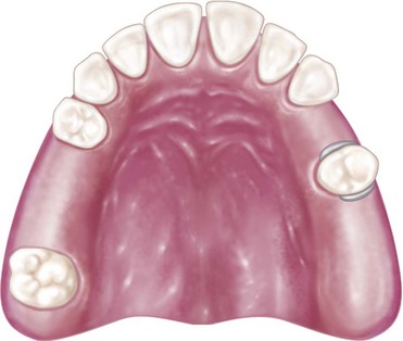
On the basis of the previous discussion, it is clear that two distinctly different types of RPDs exist. Certain points of difference are present between Kennedy Class I and Class II types of partial dentures on the one hand and the Class III type of partial denture on the other. The first consideration is the manner in which each is supported. The Class I type and the distal extension side of the Class II type derive their primary support from tissues underlying the base and secondary support from the abutment teeth (Figure 10-1, A and Figure 10-2). The Class III type derives all of its support from the abutment teeth (Figure 10-1, B and Figure 10-2).
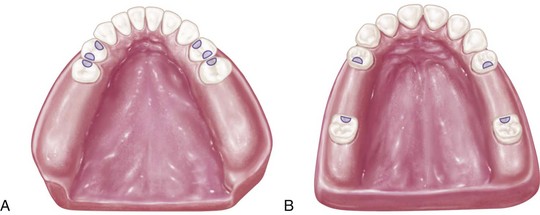
Figure 10-1 A, Kennedy Class I partially edentulous arch. Major support for denture bases must come from residual ridges, tooth support from occlusal rests being effective only at the anterior portion of each base. B, Kennedy Class III, modification 1 partially edentulous arch provides total tooth support for the prosthesis. A removable partial denture made for this arch is totally supported by rests on properly prepared occlusal rest seats on four abutment teeth.
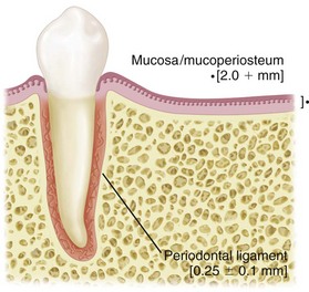
Figure 10-2 Distortion of tissues over the edentulous ridge will be approximately 500 µm under 4 newtons of force, whereas abutment teeth will demonstrate approximately 20 µm of intrusion under the same load.
Second, for reasons directly related to the manner of support, the method of impression registration and the jaw record required for each type will vary.
Third, the need for some kind of indirect retention exists in the distal extension type of partial denture, whereas in the tooth-supported, Class III type, no extension base is present to lift away from the supporting tissues because of the action of sticky foods and the movements of tissues of the mouth against the borders of the denture. This is so because each end of each denture base is secured by a direct retainer on an abutment tooth. Therefore the tooth-supported partial denture does not rotate about a fulcrum, as does the distal extension partial denture.
Fourth, the manner in which the distal extension type of partial denture is supported often necessitates the use of a base material that can be relined to compensate for tissue changes. Acrylic-resin is generally used as a base material for distal extension bases. The Class III partial denture, on the other hand, which is entirely tooth supported, does not require relining except when it is advisable to eliminate an unhygienic, unesthetic, or uncomfortable condition resulting from loss of tissue contact. Metal bases therefore are more frequently used in tooth-supported restorations, because relining is not as likely to be necessary with them.
Differences in Support
The distal extension partial denture derives its major support from the residual ridge with its fibrous connective tissue covering. The length and contour of the residual ridge significantly influence the amount of available support and stability (Figure 10-3). Some areas of this residual ridge are firm, with limited displaceability, whereas other areas are displaceable, depending on the thickness and structural character of the tissues overlying the residual alveolar bone. The movement of the base under function determines the occlusal efficiency of the partial denture and also the degree to which the abutment teeth are subjected to torque and tipping stresses.
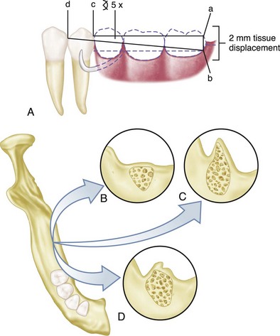
Figure 10-3 A, The longer the edentulous area covered by the denture base, the greater the potential lever action on the abutment teeth. If an extension base area is 30 mm (ac) and tissue displacement is 2 mm (ab), the amount of movement of the proximal plate on the guiding plane will be approximately 0.25 mm: [α = √ (ab)2 + (ac)2]; arc of the tangent ab/ad = x/cd (2/30 = x/3.75 = 0.25 mm). B, The flat ridge will provide good support, poor stability. C, The sharp spiny ridge will provide poor support, poor to fair stability. D, Displaceable tissue on the ridge will provide poor support and poor stability.
Impression Registration
An impression registration for the fabrication of a partial denture must fulfill the following two requirements:
No single impression material can satisfactorily fulfill both of the previously mentioned requirements. Recording the anatomic form of both teeth and supporting tissues will result in inadequate support for the distal extension base. This is so because the cast will not represent the optimum coordinating forms, which require that the ridge must be related to the teeth in a supportive form. This coordination of support maximizes the support capacity for the arch and minimizes movement of the partial denture under function.
Differences in Clasp Design
A fifth point of difference between the two main types of removable partial dentures lies in their requirements for direct retention.
The tooth-supported partial denture, which is totally supported by abutment teeth, is retained and stabilized by a clasp at each end of each edentulous space. Because this type of prosthesis does not move under function (other than within the physiologic limitations of tooth support units), the only requirement for such clasps is that they flex sufficiently during placement and removal of the denture to pass over the height of contour of the teeth in approaching or escaping from an undercut area. While in its terminal position on the tooth, a retentive clasp should be passive and should not flex except when one is engaging the undercut area of the tooth for resisting a vertical dislodging force.
Cast retentive arms are generally used for this purpose. These may be of the circumferential type, arising from the body of the clasp and approaching the undercut from an occlusal direction, or of the bar type, arising from the base of the denture and approaching the undercut area from a gingival direction. Each of these two types of cast clasps has its advantages and disadvantages.
In the combination tooth and tissue–supported RPD, because of the anticipated functional movement of the distal extension base, the direct retainer adjacent to the distal extension base must perform still another function, in addition to resisting vertical displacement. Because of the lack of tooth support distally, the denture base will move tissue-ward under function proportionate to the quality (displaceability) of the supporting soft tissues, the accuracy of the denture base, and the total occlusal load applied. Because of this tissue-ward movement, those elements of a clasp that lie in an undercut area mesial to the fulcrum for a distal extension (as is often seen with a distal rest) must be able to flex sufficiently to dissipate stresses that otherwise would be transmitted directly to the abutment tooth as leverage. On the other hand, a clasp used in conjunction with a mesial rest may not transmit as much stress to the abutment tooth because of the reduction in leverage forces that results from a change in the fulcrum position. This serves the purpose of reducing or “breaking” the stress, hence the term stress-breakers, and is a strategy that is often incorporated into partial denture designs through various means. Some dentists strongly believe that a stress-breaker is the best means of preventing leverage from being transmitted to the abutment teeth. Others believe just as strongly that a wrought-wire or bar-type retentive arm more effectively accomplishes this purpose with greater simplicity and ease of application. A retentive clasp arm made of wrought wire can flex more readily in all directions than can the cast half-round clasp arm. Thereby, it may more effectively dissipate those stresses that would otherwise be transmitted to the abutment tooth. A discussion of the limitations of stress-breakers has been presented in Chapter 9.
Only the retentive arm of the circumferential clasp, however, should be made of wrought metal. Reciprocation and stabilization against lateral and torquing movement must be obtained through use of the rigid cast elements that make up the remainder of the clasp. This is called a combination clasp because it is a combination of cast and wrought materials incorporated into one direct retainer. It is frequently used on the terminal abutment for the distal extension partial denture and is indicated where a mesiobuccal but no distobuccal undercut exists, or where a gross tissue undercut, cervical and buccal to the abutment tooth, exists. It must always be remembered that the factors of length and material contribute to the flexibility of clasp arms. From a materials physical property standpoint, a short wrought-wire arm may be a destructive element because of its reduced ability to flex compared with a longer wrought-wire arm. However, in addition to its greater flexibility compared with the cast circumferential clasp, the combination clasp offers the advantages of adjustability, minimum tooth contact, and better esthetics, which justify its occasional use in tooth-supported designs.
The amount of stress transferred to the supporting edentulous ridge(s) and the abutment teeth will depend on: (1) the direction and magnitude of the force; (2) the length of the denture base lever arm(s); (3) the quality of resistance (support from the edentulous ridges and remaining natural teeth); and (4) the design characteristics of the partial denture. As was stated in Chapter 7, the location of the rest, the design of the minor connector as it relates to its corresponding guiding plane, and the location of the retentive arm are all factors that influence how a clasp system functions. The greater the surface area contact of each minor connector to its corresponding guiding plane, the more horizontal the distribution of force (Figure 10-4).
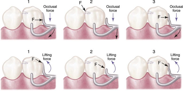
Figure 10-4 1, Maximum contact of the proximal plate minor connector with the guiding plane produces a more horizontal distribution of stress to the abutment teeth. 2, Minimum contact or disengagement of the minor connector with the guiding plane allows rotation around the fulcrum located on the mesio-occlusal rest, producing a more vertical distribution of stress to the ridge area. 3, Minor connector contact with the guiding plane from the marginal ridge to the junction of the middle and gingival thirds of the abutment tooth distributes load vertically to the ridge and horizontally to the abutment tooth. F is the location of the fulcrum of movement for the distal extension base.
Essentials of Partial Denture Design
The design of the partial denture framework should be systematically developed and outlined on an accurate diagnostic cast based on the following prosthesis concepts: where the prosthesis is supported, how the support is connected, how the prosthesis is retained, how the retention and support are connected, and how edentulous base support is connected.
In developing the design, it is first necessary to determine how the partial denture is to be supported. In an entirely tooth-supported partial denture, the most ideal location for the support units (rests) is on prepared rest seats on the occlusal, cingulum, or incisal surface of the abutment adjacent to each edentulous space (see Figure 10-1, B). The type of rest and amount of support required must be based on interpretation of the diagnostic data collected from the patient. In evaluating the potential support that an abutment tooth can provide, consideration should be given to (1) periodontal health; (2) crown and root morphologies; (3) crown-to-root ratio; (4) bone index area (how tooth has responded to previous stress); (5) location of the tooth in the arch; (6) relationship of the tooth to other support units (length of edentulous span); and (7) the opposing dentition. (For a more in-depth understanding of these considerations, review Chapters 6 and 12.)
In a tooth and tissue–supported partial denture, attention to these same considerations must be given to the abutment teeth. However, equitable support must come from the edentulous ridge areas. In evaluating the potential support available from edentulous ridge areas, consideration must be given to (1) the quality of the residual ridge, which includes contour and quality of the supporting bone (how the bone has responded to previous stress) and quality of the supporting mucosa; (2) the extent to which the residual ridge will be covered by the denture base; (3) the type and accuracy of the impression registration; (4) the accuracy of the denture base; (5) the design characteristics of the component parts of the partial denture framework; and (6) the anticipated occlusal load. A full explanation of tissue support for extension base partial dentures is found in Chapter 16.
Denture base areas adjacent to abutment teeth are primarily tooth supported. As one proceeds away from the abutment teeth, they become more tissue supported. Therefore it is necessary to incorporate characteristics in the partial denture design that will distribute the functional load equitably between the abutment teeth and the supporting tissues of the edentulous ridge. Locating tooth support units (rests) on the principal abutment teeth and designing the minor connectors that are adjacent to the edentulous areas to contact the guiding planes in such a manner that the functional load is dispersed equitably between the available tooth and tissue supporting units will provide designs with controlled distribution of support (see Figure 10-4).
The second step in systematic development of the design for any removable partial denture is to connect the tooth and tissue support units. This connection is facilitated by designing and locating major and minor connectors in compliance with the basic principles and concepts presented in Chapter 5. Major connectors must be rigid so that forces applied to any portion of the denture can be effectively distributed to the supporting structures. Minor connectors arising from the major connector make it possible to transfer functional stress to each abutment tooth through its connection to the corresponding rest and also to transfer the effects of the retainers, rests, and stabilizing components to the remainder of the denture and throughout the dental arch.
The third step is to determine how the removable partial denture is to be retained. The retention must be sufficient to resist reasonable dislodging forces. As was stated in Chapter 7, retention is accomplished by placement of mechanical retaining elements (clasps) on the abutment teeth and by the intimate relationship of the denture bases and major connectors (maxillary) with the underlying tissues. The key to selecting a successful clasp design for any given situation is to choose one that will (1) avoid direct transmission of tipping or torquing forces to the abutment; (2) accommodate the basic principles of clasp design by definitive location of component parts correctly positioned on abutment tooth surfaces; (3) provide retention against reasonable dislodging forces (with consideration for indirect retention); and (4) be compatible with undercut location, tissue contour, and esthetic desires of the patient. Location of the undercut is the most important single factor in selection of a clasp. Undercut location, however, can be modified by recontouring or restoring the abutment tooth to accommodate a clasp design better suited to satisfy the criteria for clasp selection.
The relative importance of retention is highlighted by the results from a clinical trial investigating prosthesis designs. A 5-year randomized clinical trial of two basic removable partial denture designs—one with rest, proximal plate, and I-bar (RPI) design and one with circumferential clasp design—demonstrated no discernible changes after 60 months in nine periodontal health components of the abutment teeth with either of the two designs. The overall results indicate that the two designs did not differ in terms of success rates, maintenance, or effects on abutment teeth. Therefore, a well-constructed removable partial denture that is supported by favorable abutments and good residual ridges that are properly prepared and maintained in a patient who exhibits good oral hygiene offers the best opportunity for satisfactory treatment.
The fourth step is to connect the retention units to the support units. If direct and indirect retainers are to function as designed, each must be rigidly attached to the major connector. The criteria for selection, location, and design are the same as those indicated for connecting the tooth and tissue support units.
The fifth and last step in this systematic approach to design is to outline and join the edentulous area to the already established design components. Strict attention to details of the design characteristics outlined in Chapter 9 is necessary to ensure rigidity of the base material without interfering with tooth placement.
Components of Partial Denture Design
All partial dentures have two things in common: (1) they must be supported by oral structures, and (2) they must be retained against reasonable dislodging forces.
In the Kennedy Class III partial denture, three components are necessary: support provided by rests, the connectors (stabilizing components), and the retainers.
The partial denture that does not have the advantage of tooth support at each end of each edentulous space still must be supported, but in this situation, the support comes from both the teeth and the underlying ridge tissues rather than from the teeth alone. This is a composite support, and the prosthesis must be fabricated so that the resilient support provided by the edentulous ridge is coordinated with the more stable support offered by the abutment teeth. The essentials—support, connectors, and retainers—must be designed and executed more carefully because of the movement of tissue-supported denture base areas. In addition, provision must be made for three other factors, as follows:
Tooth Support
Support of the removable partial denture by the abutment teeth is dependent on the alveolar support of those teeth, the crown and root morphology, the rigidity of the partial denture framework, and the design of the occlusal rests. Through clinical and roentgenographic interpretation, the dentist may evaluate the abutment teeth and decide whether they will provide adequate support. In some instances, the splinting of two or more teeth, either by using fixed partial dentures or by soldering two or more individual restorations together, is advisable. In other instances, a tooth may be deemed too weak to be used as an abutment, and extraction is indicated in favor of obtaining better support from an adjacent tooth.
Having decided on the abutments, the dentist is responsible for preparation and restoration of the abutment teeth to accommodate the most ideal design of the partial denture. This includes the form of the occlusal rest seats. These modifications may be prepared in sound tooth enamel or in restorative materials that will withstand the functional stress and wear of the component parts of the removable partial denture. The technician cannot be blamed for inadequate abutment tooth preparation, such as occlusal rest support. On the other hand, the technician is solely to blame if he or she extends the casting beyond, or fails to include, the total prepared areas. If the dentist has sufficiently reduced the marginal ridge area of the rest seat to avoid interference from opposing teeth, and if a definite occlusal rest seat is faithfully recorded in the master cast and delineated in the penciled design, then no excuse can be made for poor occlusal rest form on the partial denture.
Ridge Support
Support for the tooth-supported removable partial denture or the tooth-supported modification space comes entirely from the abutment teeth by means of rests. Support for the distal extension denture base comes primarily from the overlying soft tissues and the residual alveolar bone of the distal extension base area. In the latter, rest support is effective only at the abutment end of the denture base.
The effectiveness of tissue support depends on six things: (1) the quality of the residual ridge; (2) the extent to which the residual ridge will be covered by the denture base; (3) the accuracy and type of impression registration; (4) the accuracy of the denture bases; (5) the design characteristics of component parts of the partial denture framework; and (6) the occlusal load applied.
The quality of the residual ridge cannot be influenced, except that it can be improved by tissue conditioning, or it can be modified by surgical intervention. Such modifications are almost always needed but are not frequently done.
The accuracy of the impression technique is entirely in the hands of the dentist. Maximum tissue coverage for support that encompasses the primary stress–bearing areas should be the primary objective in any partial denture impression technique. The manner in which this is accomplished should be based on biological comprehension of what happens beneath a distal extension denture base when an occlusal load is applied.
The accuracy of the denture base is influenced by the choice of materials and by the exactness of the processing techniques. Inaccurate and warped denture bases adversely influence the support of the partial denture. Materials and techniques that will ensure the greatest dimensional stability should be selected.
The total occlusal load applied to the residual ridge may be influenced by reducing the area of occlusal contact. This is done with the use of fewer, narrower, and more effectively shaped artificial teeth (Figure 10-5).
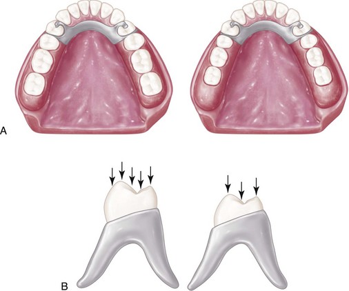
Figure 10-5 A, The total occlusal load applied may be reduced by using comparatively smaller posterior teeth represented by the right-hand illustration. B, Less muscular force will be required to penetrate a food bolus with a reduced occlusal table, thereby reducing forces to supporting oral structures.
The distal extension removable partial denture is unique in that its support is derived from abutment teeth, which are comparatively unyielding, and from soft tissues overlying bone, which may be comparatively yielding under occlusal forces. Resilient tissues, which are distorted or displaced by occlusal load, are unable to provide support for the denture base comparable with that offered by the abutment teeth. This problem of support is further complicated by the fact that the patient may have natural teeth remaining that can exert far greater occlusal force on the supporting tissues than would result if the patient were completely edentulous. This fact is clearly evident from the damage that often occurs to an edentulous ridge when it is opposed by a few remaining anterior teeth in the opposing arch, and especially when the opposing occlusion of anterior teeth has been arranged so that contact occurs in both centric and eccentric positions.
Ridge tissues recorded in their resting or nonfunctioning form are incapable of providing the composite support needed for a denture that derives its support from both hard and soft tissue. Three factors must be considered in the acceptance of an impression technique for distal extension removable partial dentures: (1) the material should record the tissues covering the primary stress–bearing areas in their supporting form; (2) tissues within the basal seat area other than primary stress–bearing areas must be recorded in their anatomic form; and (3) the total area covered by the impression should be sufficient to distribute the load over as large an area as can be tolerated by the border tissues. This is an application of the principle of the snowshoe.
Anyone who has had the opportunity to compare two master casts for the same partially edentulous arch—one cast having the distal extension area recorded in its anatomic or resting form, and the other cast having the distal extension area recorded in its functional form—has been impressed by the differences in topography (Figure 10-6). A denture base processed to the functional form is generally less irregular and provides greater area coverage than does a denture base processed to the anatomic or resting form. Moreover, and of far greater significance, a denture base made to anatomic form exhibits less stability under rotating and/or torquing forces than does a denture base processed to functional form and thus fails to maintain its occlusal relation with opposing teeth. When the patient is asked to close onto strips of soft wax, it is evident that occlusion is maintained at a point of equilibrium over a longer period of time when the denture base has been made to the functional form. In contrast, evidence indicates that rapid “settling” of the denture base occurs when it has been made to the anatomic form, with an early return of the occlusion to natural tooth contact only. Such a denture not only fails to distribute the occlusal load equitably but also allows rotational movement, which is damaging to the abutment teeth and their investing structures.
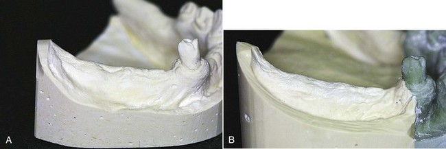
Figure 10-6 A, Cast of partially edentulous arch representing anatomic form of residual ridges. An impression was made in the stock tray by using irreversible hydrocolloid. B, An impression recording the functional or supporting form of residual ridges was made in an individualized impression tray, permitting placement of tissues and definitive border molding.
An implant can efficiently serve to improve ridge support by replacing the tissue compression seen on functional loading with the stiff resistance offered by bone supporting an implant. The benefit for movement control is achieved as if a change was made from a tooth-tissue–borne prosthesis to a tooth-tooth–borne prosthesis.
Major and Minor Connectors
Major connectors are the units of a partial denture that connect the parts of the prosthesis located on one side of the arch with those on the opposite side. Minor connectors arise from the major connector and join it with other parts of the denture; thus they serve to connect the tooth and tissue support units. A major connector should be properly located in relation to gingival and moving tissues and should be designed to be rigid. Rigidity in a major connector is necessary to provide proper distribution of forces to and from the supporting components.
A lingual bar connector should be tapered superiorly with a half-pear shape in cross section and should be relieved sufficiently but not excessively over the underlying tissues when such relief is indicated. The addition of a continuous bar retainer or a lingual apron does not alter the basic design of the lingual bar. These are added solely for support, stabilization, rigidity, and protection of the anterior teeth and are neither connectors nor indirect retainers. The finished inferior border of a lingual bar or a linguoplate should be gently rounded to avoid irritation to subjacent tissues when the restoration moves even slightly in function.
The use of a linguoplate is indicated when the lower anterior teeth are weakened by periodontal disease. It is also indicated in Kennedy Class I partially edentulous arches when additional resistance to horizontal rotation of the denture is required because of excessively resorbed residual ridges. Still another indication is seen in those situations in which the floor of the mouth so closely approximates the lingual gingiva of anterior teeth that an adequately inflexible lingual bar cannot be positioned without impinging on gingival tissues.
Experience with the linguoplate has shown that with good oral hygiene, the underlying tissues remain healthy and no harmful effects to the tissues result from the metallic coverage per se. However, adequate relief must be provided whenever a metal component crosses the gingival margins and the adjacent gingivae. Excessive relief should be avoided because tissues tend to fill a void, resulting in the overgrowth of abnormal tissue. The amount of relief used, therefore, should be only the minimum necessary to avoid gingival impingement.
It does not seem that there are many advantages to be found in the use of the continuous bar retainer versus the linguoplate. In rare instances, when a linguoplate would be visible through multiple interproximal embrasures, the continuous bar retainer may be preferred for esthetic reasons only. In other instances, when a single diastema exists, a linguoplate may be cut out in this area to avoid the display of metal, without sacrificing its use when otherwise indicated.
The rigidity of a palatal major connector is just as important and its location and design just as critical as for a lingual bar. A U-shaped palatal connector is rarely justified except to avoid an inoperable palatal torus that extends to the junction of the hard and soft palates. Neither can the routine use of a narrow, single palatal bar be justified. The combination anterior-posterior palatal strap–type major connector is mechanically and biologically sound if it is located so that it does not impinge on tissues. The broad, anatomic palatal major connector is frequently preferred because of its rigidity, better acceptance by the patient, and greater stability without tissue damage. In addition, this type of connector may provide direct-indirect retention that may sometimes, but rarely, eliminate the need for separate indirect retainers.
Direct Retainers for Tooth-Supported Partial Dentures
Retainers for tooth-supported partial dentures have only two functions: to retain the prosthesis against reasonable dislodging forces without damage to the abutment teeth, and to aid in resisting any tendency of the denture to be displaced in a horizontal plane. The prosthesis cannot move tissue-ward because the retentive components of the clasp assembly are supported by the rest. No movement away from the tissues should occur, and therefore no rotation about a fulcrum, because the retentive component is secured by a direct retainer.
Any type of direct retainer is acceptable as long as the abutment tooth is not jeopardized by its presence. Intracoronal (frictional) retainers are ideal for tooth-supported restorations and offer esthetic advantages that are not possible with extracoronal (clasp) retainers. Nevertheless, circumferential and bar-type clasp retainers are mechanically effective and are more economically constructed than are intracoronal retainers. Therefore they are more universally used.
Vulnerable areas on the abutment teeth must be protected by restorations with either type of retainer. The clasp retainer must not impinge on gingival tissues. The clasp must not exert excessive torque on the abutment tooth during placement and removal. It must be located the least distance into the tooth undercut for adequate retention, and it must be designed with a minimum of bulk and tooth contact.
The bar clasp arm should be used only when the area for retention lies close to the gingival margin of the tooth and little tissue blockout is necessary. If the clasp must be placed high, if the vestibule is extremely shallow, or if an objectionable space would exist beneath the bar clasp arm because of blockout of tissue undercuts, the bar clasp arm should not be used. In the event of an excessive tissue undercut, consideration should be given to recontouring the abutment and using some type of circumferential direct retainer.
Direct Retainers for Distal Extension Partial Dentures
Retainers for distal extension partial dentures, while retaining the prosthesis, must also be able to flex or disengage when the denture base moves tissue-ward under function. Thus the retainer may act as a stress-breaker. Mechanical stress-breakers accomplish the same thing, but they do so at the expense of horizontal stabilization. When some kind of mechanical stress-breaker is used, the denture flange must be able to prevent horizontal movement. Clasp designs that allow flexing of the retentive clasp arm may accomplish the same purpose as that of mechanical stress-breakers, without sacrificing horizontal stabilization and with less complicated techniques.
In evaluating the ability of a clasp arm to act as a stress-breaker, one must realize that flexing in one plane is not enough. The clasp arm must be freely flexible in any direction, as dictated by the stresses applied. Bulky, half-round clasp arms cannot do this, and neither can a bar clasp engaging an undercut on the side of the tooth away from the denture base. Round, tapered clasp forms offer the advantages of greater and more universal flexibility, less tooth contact, and better esthetics. Either the combination circumferential clasp with its tapered wrought-wire retentive arm or the carefully located and properly designed circumferential or bar clasp can be considered for use on all abutment teeth adjacent to extension denture bases if the abutment teeth have been properly prepared and tissue support effectively achieved, and if the patient exercises good oral hygiene.
Stabilizing Components
Stabilizing components of the removable partial denture framework are those rigid components that assist in stabilizing the denture against horizontal movement. The purpose of all stabilizing components should be to distribute stresses equally to all supporting teeth without overworking any one tooth. The minor connectors that join the rests and the clasp assemblies to the major connector serve as stabilizing components.
All minor connectors that contact vertical tooth surfaces (and all reciprocal clasp arms) act as stabilizing components. It is necessary that minor connectors have sufficient bulk to be rigid and yet present as little bulk to the tongue as possible. This means that they should be confined to interdental embrasures whenever possible. When minor connectors are located on vertical tooth surfaces, it is best that these surfaces be parallel to the path of placement. When cast restorations are used, these surfaces of the wax patterns should be made parallel on the surveyor before casting.
A modification of minor connector design has been proposed that places the minor connector in the center of the lingual surface of the abutment tooth (Figure 10-7). Proponents of this design claim that it reduces the amount of gingival tissue coverage and provides enhanced bracing and guidance during placement. Disadvantages may include increased encroachment on the tongue space, more obvious borders, and potentially greater space between the connector and the abutment tooth. This proposed variation, however, when combined with thoughtful design principles, may provide some benefit to the periodontal health of the abutment teeth and may be acceptable to some patients.
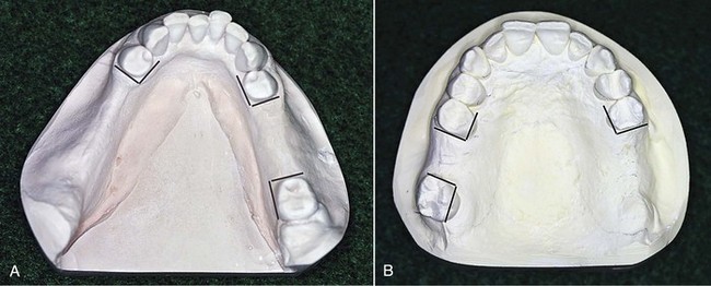
Figure 10-7 Prospective guiding plane surfaces are indicated by lines located on the respective surfaces of abutment teeth. These surfaces, when used, can be made vertically parallel to the path of placement. However, by including guiding plane surfaces, which are not in the same parallel plane horizontally (arrows) but are divergent, cross-arch resistance to horizontal rotation of the denture is enhanced.
Reciprocal clasp arms also must be rigid, and they must be placed occlusally to the height of contour of the abutment teeth, where they will be nonretentive. By their rigidity, these clasp arms reciprocate the opposing retentive clasp; they also prevent horizontal movement of the prosthesis under functional stresses. For a reciprocal clasp arm to be placed favorably, some reduction of the tooth surfaces involved is frequently necessary to increase the suprabulge area.
When crown restorations are used, a lingual reciprocal clasp arm may be inset into the tooth contour by providing a ledge on the crown on which the clasp arm may rest. This permits the use of a wider clasp arm and restores a more nearly normal tooth contour, at the same time maintaining its strength and rigidity (see Chapter 14).
Guiding Plane
The term guiding plane is defined as two or more parallel, vertical surfaces of abutment teeth, so shaped to direct a prosthesis during placement and removal. After the most favorable path of placement has been ascertained, axial surfaces of abutment teeth are prepared parallel to the path of placement, and therefore become parallel to each other. Guiding planes may be contacted by various components of the partial denture—the body of an extracoronal direct retainer, the stabilizing arm of a direct retainer, the minor connector portion of an indirect retainer—or by a minor connector specifically designed to contact the guiding plane surface.
The functions of guiding plane surfaces are as follows: (1) to provide for one path of placement and removal of the restoration (to eliminate detrimental strain to abutment teeth and framework components during placement and removal); (2) to ensure the intended actions of reciprocal, stabilizing, and retentive components (to provide retention against dislodgment of the restoration when the dislodging force is directed other than parallel to the path of removal and also to provide stabilization against horizontal rotation of the denture); and (3) to eliminate gross food traps between abutment teeth and components of the denture.
Guiding plane surfaces need to be created so that they are as nearly parallel to the long axes of abutment teeth as possible. Establishing guiding planes on several abutment teeth (preferably more than two teeth), located at widely separated positions in the dental arch, provides for more effective use of these surfaces. The effectiveness of guiding plane surfaces is enhanced if these surfaces are prepared on more than one common axial surface of the abutment teeth (see Figure 10-7).
As a rule, proximal guiding plane surfaces should be about one-half the width of the distance between the tips of adjacent buccal and lingual cusps, or about one-third the buccal lingual width of the tooth, and should extend vertically about two thirds of the length of the enamel crown portion of the tooth from the marginal ridge cervically. In the preparation of guiding plane surfaces, care must be exercised to avoid creating buccal or lingual line angles (Figure 10-8). If it is assumed that the stabilizing or retentive arm of a direct retainer may originate in the guiding plane region, a line angle preparation would weaken either or both components of the clasp assembly.
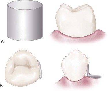
Figure 10-8 A, The guiding plane surface should be like an area on a cylindrical object. It should be a continuous surface unbounded by even, rounded line angles. B, Minor connector contacting the guiding plane surface has the same curvature as that surface.
From an occlusal view, it tapers buccally from the thicker lingual portion, thus permitting closer contact of the abutment tooth and the prosthetically supplied tooth. Viewed from the buccal aspect, the minor connector contacts the enamel of the tooth on its proximal surface about two-thirds its length.
A guiding plane should be located on the abutment surface adjacent to an edentulous area. However, excess torquing is inevitable if the guiding planes squarely facing each other on a lone standing abutment adjacent to an extension area are used (Figure 10-9).
Indirect Retainers
An indirect retainer must be placed as far anterior from the fulcrum line as adequate tooth support permits, if it is to function with the direct retainer to restrict movement of a distal extension base away from the basal seat tissues. It must be placed on a rest seat prepared in an abutment tooth that is capable of withstanding the forces placed on it. An indirect retainer cannot function effectively on an inclined tooth surface, nor can a single weak incisor tooth be used for this purpose. A canine or premolar tooth should be used for the support of an indirect retainer, and the rest seat must be prepared with as much care as is given any other rest seat. An incisal rest or a lingual rest may be used on an anterior tooth, provided a definite seat can be obtained in sound enamel or on a suitable restoration.
A second purpose that indirect retainers serve in partial denture design is that of support for major connectors. A long lingual bar or an anterior palatal major connector is thereby prevented from settling into the tissues. Even in the absence of a need for indirect retention, provision for such auxiliary support is sometimes indicated.
Contrary to common use, a cingulum bar or a linguoplate does not in itself act as an indirect retainer. Because these are located on inclined tooth surfaces, they serve more as orthodontic appliances than as support for the partial denture. When a linguoplate or a cingulum bar is used, terminal rests should always be provided at either end to stabilize the denture and to prevent orthodontic movement of the teeth contacted. Such terminal rests may function as indirect retainers, but they would function equally well in that capacity without the continuous bar retainer or linguoplate.
Implant Considerations in Design
As was mentioned in Chapter 4, the objectives of RPD design are to replace missing teeth with a prosthesis that exhibits limited movement under the influence of functional forces, and to ensure that movement is within physiologic tolerance. Physiologic tolerance would include tissue tolerance as well as a patient’s physiologic ability to accommodate to the prosthesis.
The Kennedy Class III tooth–supported RPD presents less of a challenge to oral tissues and patient accommodation than does the Kennedy Class I or II tooth-tissue prosthesis. The challenge is chiefly related to prosthesis movement to an extent allowed by tissue displaceability under an applied force. Use of dental implants to reduce this displacement can significantly benefit tissue tolerability and reduce any challenge to accommodation presented by prosthesis movement. Use of implants can also assist other worthwhile goals such as improved stability and retention when these aspects are needed because of anatomic deficiencies or related factors.
The clinician must consider potential movements of the prosthesis and the ability to control movement given the existing oral tissues, teeth, and occlusion. Selective application of dental implants can provide needed movement control.
Examples of Systematic Approach to Design
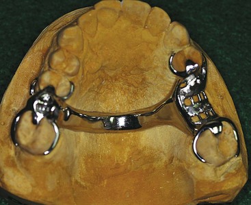
Class III Removable Partial Denture
The Kennedy Class III removable partial denture (Figures 10-10 and 10-11), entirely tooth supported, may be made to fit the prepared surfaces of the anatomic form of the teeth and surrounding structures. It does not require an impression of the functional form of the ridge tissues, nor does it require indirect retention. Cast clasps of the circumferential variety, the bar type, or the combination clasp may be used, depending on how one can modify the surfaces of the abutment teeth (guiding planes, rests, contours for proper location of clasp arms). Unless the need for later relining is anticipated, as in the situation of recently extracted teeth, the denture base may be made of metal, which offers several advantages. The Class III partial denture can frequently be used as a valuable aid in periodontal treatment because of its stabilizing influence on the remaining teeth.
Kennedy Class I, Bilateral, Distal Extension Removable Partial Dentures
The Class I, bilateral, distal extension partial denture is as different from the Class III type as any two dental restorations could be (see Figure 10-1). Because it derives its principal support from the tissues underlying its base, a Class I partial denture made to anatomic ridge form cannot provide uniform and adequate support. Yet, unfortunately, many Class I mandibular removable partial dentures are made from a single irreversible hydrocolloid impression. In such situations, both the abutment teeth and the residual ridges suffer because the occlusal load placed on the remaining teeth is increased by the lack of adequate posterior support.
Many dentists, recognizing the need for some type of impression registration that will record the supporting form of the residual ridge, attempt to record this form with a metallic oxide, a rubber base, or one of the silicone impression materials. Such materials actually record only the anatomic form of the ridge, except when the special design of impression trays permits recording of the primary stress–bearing areas under a simulated load. Others prefer to place a base, made to fit the anatomic form of the ridge, under some pressure at the time that it is related to the remaining teeth, thus obtaining functional support. Still others, who believe that a properly compounded mouth-temperature wax will displace only those tissues that are incapable of providing support to the denture base, use a wax secondary impression to record the supporting, or functional, form of the edentulous ridge. Any impression record will be influenced by the consistency of the impression material and the amount of hydraulic pressure exerted by its confinement within the impression tray.
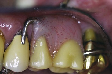
Kennedy Class II Removable Partial Dentures
The Kennedy Class II partial denture (Figures 10-12 and 10-13) actually may be a combination of tissue-supported and tooth-supported restorations. The distal extension base must have adequate tissue support, whereas tooth-supported bases elsewhere in the arch may be made to fit the anatomic form of the underlying ridge. Indirect retention must be provided for; however, occasionally the anterior abutment on the tooth-supported side will satisfy this requirement. If additional indirect retention is needed, provisions must be made for it.
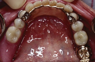
Figure 10-12 Mandibular Class II removable partial denture with distal extension base. Because of tissue undercut cervical to the buccal surface of the right second premolar and lack of distobuccal undercut, a wrought-wire (tapered) retainer arm was used.
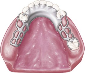
Figure 10-13 Mandibular Class II, modification 1 partially edentulous arch. Note that bar-type retentive arms are used on both premolar abutments, engaging distobuccal undercuts at their terminal ends. Leverlike forces may not be as readily imparted to the right premolar, as opposed to the cast circumferential direct retainer engaging the mesiobuccal undercut.
Cast clasps are generally used on the tooth-supported side; however, a clasp design in which wrought wire is used may reduce the application of torque on the abutment tooth adjacent to the distal extension and should be considered. The use of a cast circumferential clasp engaging a mesiobuccal undercut on the anterior abutment of the tooth-supported modification space may result in a Class I leverlike action if the abutment teeth have not been properly prepared, and/or if tissue support from the extension base area is not adequate. It seems rational under these circumstances to minimize these effects through optimum denture base adaptation, to reduce movement or to provide implant support (see Figure 10-13). Should the bar-type retainer be contraindicated because of a severe tissue undercut or the existence of only a mesiobuccal undercut on the anterior abutment, then a combination direct retainer with the retentive arm made of tapered wrought wire should be used. A thorough understanding of the advantages and disadvantages of various clasp designs is necessary in determining the type of direct retainer that is to be used for each abutment tooth.
Steps included in fabrication of the Class II partial denture closely follow those used with the Class I partial denture, except that the distal extension base is usually made of an acrylic-resin material, whereas the base for any tooth-supported area can be made of metal. This is permissible because the residual ridge beneath tooth-supported bases is not called on to provide support for the denture, and later rebasing is not as likely to be necessary.
Additional Considerations Influencing Design
Every effort should be made to gain the greatest support possible for removable prostheses with the use of abutments bounding edentulous spaces. This not only will relieve the residual ridges of some of their obligation for support but also may allow the design of the framework to be greatly simplified. To this end, use of splint bars, internal clip attachments, overlay abutments, overlay attachments, a component partial, and implants should be considered.
Use of a Splint Bar for Denture Support
In the Chapter 14 discussion of missing anterior teeth, mention is made of the fact that missing anterior teeth are best replaced with a fixed partial denture. The following is quoted from that chapter: “From a biomechanical standpoint … a removable partial denture should replace only the missing posterior teeth after the remainder of the arch has been made intact by fixed restorations.”
Occasionally, a situation is found in which it is necessary for several missing anterior teeth to be replaced by the removable partial denture rather than by fixed restorations. This may be caused by the length of the edentulous span or by the loss of a large amount of the residual ridge due to resorption, accident, or surgery, or it may result from a situation in which too much vertical space prevents the use of a fixed partial denture, or in which esthetic requirements can better be met through the use of teeth added to the denture framework. In such instances it is necessary that the best possible support for the replaced anterior teeth be provided. Ordinarily this is done through the placement of occlusal or lingual rests, or both, on the adjacent natural teeth, but when the edentulous span is too large to ensure adequate support from the adjacent teeth, other methods must be used. This is included here only because it influences the design of the major connector that must then be used.
An anterior splint bar may be attached to the adjacent abutment teeth in such a manner that fixed splinting of the abutment teeth results, with a smooth, contoured bar resting lightly on the gingival tissues to support the removable partial denture. As with any fixed partial denture, the type of abutment retainers and the decision to use multiple abutments will depend on the length of the span and the available support and stability of the teeth being used as abutments. Regardless of the type of abutment retainers used, the connecting bar may be cast of a rigid alloy, or a commercially available bar may be used and cast to the abutments or attached to the abutments by soldering.
The length of the span influences the size of a splint bar. Long spans require more rigid bars (10-gauge) than short spans (13-gauge). If the bar is to be soldered, it is best that recesses be formed in the proximal surfaces of the abutments and that the connecting bar, which rests lightly on the tissues, be cast or made to fit into these recesses and then attached by soldering.
Because of the greater rigidity of chromium-cobalt alloys, the splint bar is preferably cast in one of these materials and then is attached to the abutments by soldering. The complete assembly (abutments and connecting bar) is then cemented permanently to the abutment teeth, in the same way as for a fixed partial denture. The impression for the partial denture is then made, and a master cast is obtained that accurately reproduces the contours of the abutments and the splint bar. The denture framework then is made to fit the abutments and the bar by extending the major connector or minor connectors to cover and rest upon the splint bar. Retention for the attachment of a resin base, or any other acceptable means of attaching the replaced anterior teeth, is incorporated into the denture design. In those situations wherein the removable partial denture will be tooth supported, the splint bar may be curved to follow the crest of the residual ridge. However, in a distal extension situation, because of the vertical rotation of the denture, caution must be exercised to form the splint bar so that excessive torque will not accrue to its supporting abutments (Figure 10-14). The proximal contours of abutments adjacent to splint bars should be parallel to the path of placement. This serves three purposes: (1) it permits a desirable arrangement of artificial teeth; (2) it aids in resisting horizontal rotation of the restoration; and (3) these components act as guiding planes to direct the partial denture to and from its terminal position.
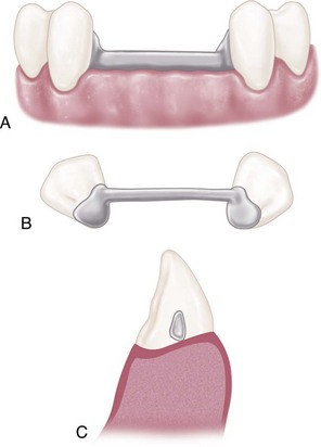
Figure 10-14 A, Insofar as is possible, the splint bar should be round or ovoid. Provisions must be made in the construction and location of the bar so that dental floss may be threaded underneath the bar to allow proper cleaning by the patient. B, As viewed from above, the bar is in a straight line between abutments. This is especially critical for distal extension removable partial dentures to avoid excess torque on abutments as the denture rotates in function. C, Sagittal section through the bar demonstrates the rounded form of the bar making point contact with the residual ridge. The entire tissue surface of the bar is easily accessible for cleaning with dental floss. A pear-shaped bar (in cross section) will permit rotation of the removable partial denture without appreciable resistance or torque.
The splint bar must be positioned anteroposteriorly just lingual to the residual ridge to allow an esthetic arrangement of artificial teeth. The resulting partial denture offers esthetic advantages of removable anterior replacements and positive support, retention, and stability from the underlying splint bar (Figure 10-15).
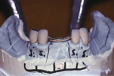
Figure 10-15 Lower canines splinted together with a splint bar. The longevity of these teeth is greatly enhanced by splinting. Tissue surfaces are minimally contacted by the rounded form of the lower portion of the bar. Anterior and posterior slopes of the splint bar must be compatible with the path of placement of the denture. Floss will be used by the patient to clean the inferior portion of the splint bar.
Internal Clip Attachment
The internal clip attachment differs from the splint bar in that the internal clip attachment provides both support and retention from the connecting bar.
Several preformed connecting bars are commercially available in plastic patterns. These can be customized for length and cast in the metal alloy of choice. Internal clip attachments are also commercially available in various metal alloys and durable nylon. When a custom-made connecting bar and clip is fabricated, the bar should be cast from 10- or 13-gauge sprue wax. The cast bar should rest lightly or should be located slightly above the tissues. Retention is provided by one of the commercial preformed metal or nylon clips, which is contoured to fit the bar and is retained in a preformed metal housing or partially embedded by means of retention spurs or loops into the overlying resin denture base.
The internal clip attachment thus provides support, stability, and retention for the anterior modification area and may serve to eliminate both occlusal rests and retentive clasps on adjacent abutment teeth.
Overlay Abutment as Support for a Denture Base
Every consideration should be directed toward preventing the need for a distal extension removable partial denture. In many instances, it is possible to salvage the roots and a portion of the crown of a badly broken-down molar through endodontic treatment. A periodontally involved molar, otherwise indicated for extraction, sometimes may be salvaged by periodontal and endodontic treatment accompanied by reduction of the clinical crown almost level with the gingival tissues. In another situation, an unopposed molar may have extruded to such an extent that restoring the tooth with a crown is inadequate to develop a harmonious occlusion. Then too, it is not unusual to encounter a molar that is so grossly tipped anteriorly that it cannot serve as an abutment unless the clinical crown is reduced drastically.
Such teeth should be considered for possible support for an otherwise distal extension denture base. Endodontic treatment and preparation of the coronal portion of the tooth as a slightly elevated dome-shaped abutment often offer an alternative to a distal extension base. The student is referred to the “Selected Reading Resources” section (textbooks; abutment retainers) for sources of information on overdenture abutments and overlay-type prostheses.
Use of a Component Partial to Gain Support
A component partial is a removable partial denture in which the framework is designed and fabricated in separate parts. The tooth support and tissue-supported components are individually fabricated, and the two are joined with a high-impact acrylic-resin to become a single rigid functioning unit.