Applying the Outcomes of Needs Identification and Physical-Sensory Evaluations to Control Interface Selection

In Figure 7-9 we list specific information related to human/technology interface selection that is an outcome of the needs identification process. The information gathered reveals particular factors that should be considered during the interface selection process. For example, identifying the activity the consumer wants to perform provides us with information on how large an input domain is required and possible control interfaces to consider. If the consumer is in need of a power wheelchair and is not interested in using a computer, for example, it is not necessary to determine whether he or she can use a keyboard. Alternatively, the consumer may need to perform several functional activities (e.g., communication, mobility, and environmental control), which affects the selection of an interface. In situations such as this, it should be considered whether a different control interface for each function or a single integrated control for all the functions is to be used.

The information gathered during the physical-sensory skills evaluation gives us a profile of the user’s skills in these areas, specifically those shown in Figure 7-9. This information can be used to determine the acceptable parameters for potential control interfaces. The range measurement determines the consumer’s minimal and maximal comfortable reach and defines the geometrical requirements for the individual’s workspace. This parameter provides an indication of the possible locations for placement of a control interface (or interfaces) and the maximal distance between the extreme outer edges of the interface (e.g., the overall size of a keyboard or switch array). The resolution measurement provides data on the consumer’s ability to control his or her movement to select targets.

Given this information on the consumer’s skills, potential candidate control interfaces that have similar characteristics in terms of the number and spacing of the targets and the size of individual switches or keys can be selected. Once candidate interfaces have been selected, comparative testing is conducted. The purpose of comparative testing using the control interfaces is to provide the ATP with information on how fast the consumer can input using the control interface and the accuracy of that input. Methods for carrying out comparative testing are described in Chapter 4. During comparative testing, it is also critical that the ATP gather subjective information from the consumer on each interface that is evaluated. This information includes the ease or difficulty of use.

Case Study

Comparative Evaluation

Max is an 18-year-old man who has cerebral palsy. He lives in a residential facility and attends a work program through United Cerebral Palsy. Max has been referred to ABC Assistive Technology Center for a communication device. He currently communicates with others by using a manual communication board and eye blinks for yes and no.

Through evaluation of Max’s range and resolution, it has been determined that his best control sites are his right hand and his head. However, he does not have fine enough control at either site to use direct selection. The ATP decides to perform comparative interface testing by using a tread switch with Max’s hand and a lever switch at the side of his head. Data collected during the comparative testing phase of the evaluation show that Max is more accurate and faster activating the switch with his head (versus his hand). However, Max has indicated a preference for using his hand instead of his head.

Questions

1. Given Max’s limited verbal communication, how would the ATP gather information from him regarding his opinion on the hand and the head switches?

2. What type of subjective information would the ATP want to gather from Max regarding his use of and preference for each of these two switches?

3. The data indicate that Max is faster and more accurate using the head switch. However, Max has indicated that he prefers the hand switch. What would the ATP’s recommendation be and why?

Control Enhancers: Interface Positioning, Arm Supports, Mouthsticks, Head Pointers, and Hand Pointers

Control enhancers are aids and strategies that enhance or extend the physical control (range and resolution) a person has available to use a control interface. In some cases a person’s control may be enhanced to the extent that he or she can select directly. In other cases control enhancers can minimize fatigue. Control enhancers include strategies, such as varying the position or the characteristics of the control interface, and devices, such as mouthsticks, head and hand pointers, and arm supports.

The person and the control interface should both be positioned to maximize function. The importance of proper positioning to maximize an individual’s function is discussed in Chapter 6. A person’s position should be observed before and during the control interface evaluation. If inadequate positioning appears to be affecting the person’s ability to control an interface, it should be addressed before continuing with the evaluation. The position of the control interface can also affect the person’s ability to activate it. Changing the height or the angle of the control interface even slightly may enhance the person’s ability to control it.

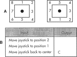
As control interfaces become more sophisticated, control-enhancing features are becoming part of the interface. For example, certain joysticks have a feature called tremor dampening that allows adjustment of the joystick for people who have tremors. Tremor-dampening joysticks are able to distinguish between tremors, which are faster and smaller, and intentional movements, which are slower and larger. The joystick is adjusted so that the tremors are disregarded and only intentional movements are detected. This adjustment enhances the ability of an individual who might otherwise be unable to operate a joystick to control a power wheelchair. A similar feature, called filter keys, is used in Windows. When the filter keys feature is activated in Windows, brief keystrokes are ignored and the rate at which keys repeat when being pressed is delayed.

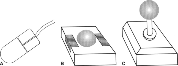
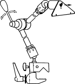
Individuals who have weakness in the arm may not have enough strength to access the full range of a keyboard adequately. A mobile arm support (Figure 7-10, A), which props the arm and assists in arm movements by eliminating some of the effects of gravity, may then allow the individual to access a keyboard. For the individual who has the gross motor ability to move his or her arm and hand around a keyboard but has difficulty extending and isolating a finger to depress a key, a pointing aid may help. There are commercially available aids that can be strapped on to the hand to assist in pointing, such as the typing aid shown in Figure 7-10, B. In some cases it is necessary to custom fabricate a pointing aid for it to fit the consumer’s hand appropriately. These custom-fabricated aids can range from complex hand splints to simple tools such as a pencil with an enlarged eraser.

image

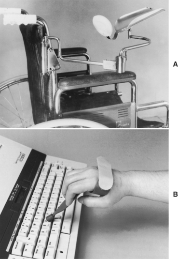
Figure 7-10 Control enhancers. A, Mobile arm support used to enhance the control in the upper extremity for accessing a control interface. B, Typing aid used to enhance a person’s ability to point and access a keyboard. (Courtesy Sammons Preston Co., Bolingbrook, Ill.)

For individuals who lack functional movement in their arms and hands, a mouthstick or head pointer (Figure 7-11) can be used with head and neck movement to access a keyboard or perform other types of manipulation tasks (e.g., dialing a telephone number or turning pages in a book) (see Chapter 14). For a head pointer, a rod with a rubber tip is attached to a band that is worn around the top of the head. The individual can then use the end of this rod to depress keys. Besides being able to move the head vertically and horizontally, the individual must have the ability to produce a third dimension of movement to depress keys with a head pointer: forward and backward. There are also light pointers that can be worn on the head or held in the hand to control devices. One advantage of head-controlled light pointers is that it is not necessary for the user to move the head forward or backward. Light pointers are described in greater detail in the section on pointing interfaces.

image

Figure 7-11 Control enhancers. A, Mouthstick. B, Head pointer.

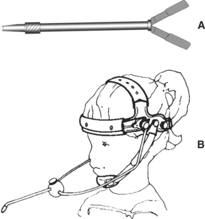
Mouthsticks are often used by individuals who are quadriplegic as a result of a spinal cord injury. A mouthstick consists of a pointer attached to a mouthpiece. The user grips the mouthpiece between the teeth and moves the head to manipulate control interfaces or other objects. The shaft of the mouthstick can be made from a wooden dowel, a piece of plastic, or aluminum. In some cases, interchangeable tips for different functions (e.g., painting, writing, typing) can be inserted into the distal end of the shaft. The mouthpiece can be a standard U shape that is gripped between the teeth or a custom-made insert. Puckett et al (1988) identify a number of criteria for design of a mouthstick. Mouthsticks are also available from several suppliers. Use of a mouthstick requires good oral-motor control; later in this chapter training to develop these skills is discussed.

The consumer’s range and resolution with the control enhancer can be determined by using the same methods discussed in Chapter 4. In some cases, particularly if there is a need to extend the consumer’s range (e.g., when the head is the likely control site), it is apparent at the beginning of the evaluation that the consumer will benefit from using a control enhancer. When the user has adequate range but resolution is in question, it may not be obvious during the physical-sensory evaluation whether a control enhancer will be beneficial. In these cases it is recommended that comparative testing of candidate interfaces with and without the use of control enhancers be completed. This evaluation provides the ATP with objective data regarding the effectiveness of the control enhancer. Certain control interfaces, however, cannot be activated with a control enhancer. These include displays specially designed to be used with light pointers, eye-controlled systems, or capacitive switches requiring skin contact for activation (Lee and Thomas, 1990).

CONTROL INTERFACES FOR DIRECT SELECTION

Because the most rapid selection method is direct selection, it is generally preferable to indirect selection. Control interfaces for direct selection include various types of keyboards, pointing interfaces, speech recognition, eye-gaze, gesture recognition and cortical signals. Several of these approaches use on-screen keyboards. The critical questions presented in Box 7-2 can assist the ATP in determining the consumer’s ability to use any keyboard. As each question is considered, a “yes” answer means that the evaluation is proceeding on the correct pathway and the ATP should continue with the next question. Affirmative responses to all seven questions indicate that the control interface by itself is likely to meet the consumer’s needs.

The answer to the first question is determined by asking the consumer to reach the keys at each corner of the keyboard. To obtain an answer to the second question, the consumer should be asked to press several keys located in different areas of the keyboard. The consumer’s rate of input can be timed for entering characters. Accuracy can be measured by monitoring errors made during these tasks. In some situations, speed is of primary importance (e.g., in a work setting). In general, speed and accuracy are in opposition; that is, as speed increases, accuracy decreases. In some cases, to be accurate the consumer may make selections so slowly and deliberately that the use of the control interface under investigation becomes impractical. For example, if it takes several seconds to select a key, this rate may be equivalent to the use of scanning to make a selection. Because scanning takes much less physical effort, it should then be considered as an alternative to direct selection. Computer-assisted methods to measure speed and accuracy data are described in Chapter 4. The criterion for accuracy is somewhat subjective and is subject to clinical judgment. We recommend that at least three out of four selections (75%) be correct.

If the answer to any of the questions in Box 7-2 is determined to be “no,” then the use of a control enhancer, modifications, or a less-limiting keyboard should be considered. For example, if a standard keyboard cannot be used because of a targeting problem, the following may be considered: (1) an enlarged keyboard with larger targets (less limiting), (2) a keyguard (modification), or (3) a typing aid (a control enhancer). Modifications apply to all types of keyboards and are addressed after the discussion of the different types of keyboards.

Keyboards

For written communication, a keyboard is typically considered the most efficient means of inputting information. The standard keyboard is the first choice for computer access. However, many individuals with disabilities are unable to use a standard keyboard. Fortunately, there are a number of alternatives. Table 7-2 provides examples of some commercially available alternatives to the standard keyboard.

Standard Keyboards.

Some individuals may have difficulty writing because of fatigue or minimally impaired motor control. A standard keyboard on a computer may be all that is needed to allow them to complete writing tasks effectively. Because it is readily available, the standard keyboard is the most desirable interface for direct selection for text entry. The standard keyboard typically has a full alphanumerical array consisting of letters, numbers, punctuation symbols, and special characters such as V@#$%. Computer keyboards also have special keys. Some of these always have the same effect, such as END, which moves the cursor to the end of a line, or DEL, which erases an entry. Function keys can be assigned to special purposes dictated by a software application. In addition, most computer keyboards contain keys such as SHIFT, CONTROL, and ALT that are referred to as modifier keys because pressing one of these keys while another key is pressed changes the meaning of the second key. Key size, spacing, and amount of distance the keys travel vary depending on the type and manufacturer of the keyboard. To keep the overall size down, laptop computers in particular have smaller keyboards. For this reason, it is wise to have the consumer try the particular type of keyboard he or she will be using.

Built-in Software Adaptations to the Standard Keyboard.

Persons with disabilities often have difficulty in pressing more than one key at a time because they are single-finger typists. They may also have accidental key activation as a result of poor fine motor control. Software adaptations for these and other problems are shown in Table 7-1. These software adaptations are built into Windows and Apple Macintosh operating systems. Collectively these are called accessibility options in Windows XP (Microsoft accessibility Web site: http://www.microsoft.com/enable/products/windowsxp/default.aspx), Easy Access in Windows Vista (Microsoft accessibility Web site), and Universal Access for the Macintosh. They are accessed and adjusted for an individual user through the control panel. Universal access for the Macintosh includes Easy Access and CloseView. Easy Access features are those shown in Table 7-1. When StickyKeys is used, the modifier keys are converted to sequential rather than simultaneous use, which allows other effectors (e.g., the head and foot) to also be used to access standard keyboards. In many cases there is also a need for StickyKeys (Windows and Macintosh) and FilterKeys (Windows) or SlowKeys (Macintosh) adaptations. FilterKeys includes the functions of BounceKeys, SlowKeys, and RepeatKeys. In Windows a number of options can be chosen to make the keyboard and mouse faster and easier to use. Options that can be adjusted are described on the Microsoft Web site (www.microsoft.com/enable/products/windowsxp/default.aspx).

There is an on-screen keyboard utility in Windows that operates in a manner similar to those described later in this chapter, but it has only basic functionality. Two modes of entry are available when an on-screen key is highlighted by mouse cursor movement: clicking and dwelling. In the latter the user keeps the mouse pointer on an on-screen key for an adjustable, preset time and the key is entered. The on-screen feature also allows entry by scanning with a hot key or switch-input device. Several keyboard configurations are included, and an auditory click may be activated to indicate entry of a character. Windows combines the on-screen keyboard, Narrator, and the magnifier program and a utility manager in its accessibility menu, which is accessed through the start menu. The Accessibility Wizard guides the user through the accessibility options to configure the system specifically for his or her use. Windows Vista also includes a built-in automatic speech recognition system.

Ergonomic Keyboards.

The term repetitive strain injury (RSI) encompasses several musculoskeletal disorders that develop as a result of sustained, repetitive movements (Bear-Lehman, 1995). Carpal tunnel syndrome is the most common RSI. It is thought that the use of a standard keyboard with horizontal rows on a flat platform may contribute to RSI in some individuals. Standard keyboards place the hands in an unnatural position with the forearms pronated and the wrists extended and ulnarly deviated. This position causes strain on the tendons and nerves. Numerous alternatives to the standard keyboard have been developed in attempts to reduce this strain on the wrist and hands. These alternatives range from minor rearranging of the keys to major redesign of the keyboard shape and configuration. Here ergonomic keyboards, those keyboards that have been designed with the intent of minimizing the risk of RSI, are discussed. These ergonomic keyboards all use the QWERTY keyboard layout (see Figure 7-12, A) with the keys repositioned in some way. Later in this section modifications to the standard QWERTY keyboard layout are discussed.

image

Figure 7-12 A, Standard QWERTY layout. Dvorak keyboard layouts: B, two-hand layout; C, one-hand layout, right hand; D, Chubon keyboard layout for a typist who uses a single digit or a typing stick.

Ergonomic keyboards attempt to reduce the strain placed on the hands and wrists during the repetitive motion of keying by putting the forearms, wrists, and hands in a neutral position, which is more natural and more comfortable for the typist. There are three basic ways in which the standard keyboard has been redesigned. The first and most common type of ergonomic keyboard is the fixed-split keyboard. In this type of keyboard the layout of the keys is split into two different sections. The center of the keyboard may also be slightly raised with a small slope toward each side. The difference between these keyboards and standard keyboards is that the keys are spaced farther apart and the keyboard is curved so that the hands are placed in a more neutral position. Many of these keyboards have a built-in wrist rest to support the wrists during typing. The Tru-Form Keyboard shown in Figure 7-13, A, is one example of this type of keyboard.

image

Figure 7-13 Ergonomic keyboards. A, The Tru-Form Keyboard. B, The Maxim Adjustable Keyboard. C, The Contoured Keyboard. (A, Courtesy Adesso Inc., www.adessoinc.com; B and C, courtesy Kinesis Corporation, www.kinesis-ergo.com.)

The second basic type of ergonomic keyboard is the adjustable-split keyboard. This type also splits the keyboard layout into two parts. A mechanism on the keyboard allows one or both sides of the keyboard to be adjusted horizontally and vertically to the position where it is most comfortable. Each section of the split keyboard typically adjusts from 0 to 30 degrees. A user who is a 10-finger typist and does not need to look at the keyboard may be able to take advantage of this range of adjustment. However, for those individuals who need to have the keyboard in the visual field, adjusting the angle too far may make it difficult to see the keys. An example of this type of keyboard is the Maxim Adjustable Keyboard shown in Figure 7-13, B.

The third type of ergonomic keyboard uses a concave keywell design. The keyboard layout again is split into two sections, but in this design the keys are arranged in a well such as that shown on the Contoured Keyboard in Figure 7-13, C. The principle behind this design is that finger excursion is reduced by having the keys arranged at the same distance from each of the finger joints (Anson, 1997). Other products for all three types of ergonomic keyboards can be found at www.tifaq.org/keyboards.html.

Manufacturers of ergonomic keyboards claim that their keyboards reduce the strain placed on the wrist and hands. However, the use of ergonomic keyboards in reducing symptoms of RSI has not been demonstrated in controlled studies. For this reason, it is advised that ergonomic keyboards not be recommended for the purpose of preventing RSI (Anson, 1997; Tessler, 1993). Situations in which an ergonomic keyboard may be recommended for a consumer include (1) meeting the needs of consumer with physical limitations (e.g., limits in range of motion) and (2) when the consumer finds the ergonomic keyboard more comfortable to use than a standard keyboard. The most critical factor to consider when selecting a keyboard is the user’s level of comfort with the different keyboards (Anson, 1997).

Expanded Keyboards.

Individuals who do not have sufficient resolution to target the keys on a standard keyboard but still have adequate resolution to select directly may be able to use an expanded keyboard. Expanded keyboards are generally membrane-type keyboards that have enlarged target areas from which the individual can select directly (Figure 7-14, A). The minimum size of the target areas on an expanded keyboard is 1 inch square. If the person still has difficulty targeting this size of key, the expanded keyboard can be customized by grouping keys together to form larger keys. In this way the keyboard can be redesigned to match the skills of the user.

image

Figure 7-14 A, Consumer using an expanded keyboard with thumb. B, Expanded keyboard showing configuration with different sizes and shapes of keys on the same keyboard.

Expanded keyboards vary in overall size and can be chosen depending on the size of the selection set needed by the individual and the key size the individual is able to target accurately. IntelliKeys has a large surface area that can be configured for a variety of key sizes and shapes. It comes with several standard keyboard overlays, such as the one shown in Figure 7-14, B. This overlay is an example of a layout that has been configured with different sizes and different shapes of keys on the same keyboard. The IntelliKeys can also be customized to match specific applications by using the companion Overlay Maker software. The keys can be labeled with letters, words, symbols, or pictures. Because they can be customized, expanded keyboards are also useful with individuals who have a cognitive or visual impairment. Examples of expanded keyboards are shown in Table 7-2.

Contracted Keyboards.

Some individuals may have sufficient resolution but lack the range of movement to reach all the keys on a standard keyboard. In this situation a contracted, or mini, keyboard may be the solution. These keyboards use either raised keys or a membrane surface. For computer use, contracted keyboards must meet the requirement that all keys of the standard keyboard be represented, which is accomplished by using additional modifier keys. Figure 7-15 shows a consumer being evaluated using a mouthstick with the USB Mini keyboard. This keyboard is approximately 7.25 × 4.2 inches in overall size, with the size of each key approximately one half inch on a side. Several of the keys have multiple functions, depending on which modifier key is pressed first. The functions corresponding to various modifiers can be colored to match the modifier key. The selection set (the alphabet) in Figure 7-15 is not placed in the QWERTY format typical of standard keyboards. The letter placement is based on a “frequency of use” system in which the letters most commonly used in the English language are placed toward the center, with the less commonly used letters placed in the outer edges of the keyboard. This arrangement particularly makes sense to use on a contracted keyboard where the individual’s range of motion is restricted. Because of the small key size and closeness of the keys, the user of a contracted keyboard must have good fine motor control. Persons using contracted keyboards type with a single digit, a handheld typing stick, or a mouthstick.

image

Figure 7-15 Consumer using the WinMini Keyboard and a mouthstick being evaluated.

Special-Purpose Keyboards.

Keyboards are also used on special-purpose devices, such as augmentative communication and environmental control devices. In these cases the available keys may be much more limited in number or they may be very specific in function compared with the standard keyboard. For example, in portable augmentative communication devices such as the SpringBoard, the keyboards have membrane keys and are restricted to a total of 32 keys (see Chapter 11). These keys are not assigned any specific character or function when manufactured but can be programmed to represent just about anything the user would like. Other devices come with certain keys that have been designated to be specific functions. For example, a key may be designated “SPEAK,” and pressing it will cause whatever was entered to be spoken. In all these cases, however, the keyboard provides the same function: direct selection input from the user to the processor.

Dedicated communication devices can also be used as input devices for a general-purpose computer. The communication device is connected to the computer through a serial or USB interface. This connection allows the communication device to send characters to the computer as if they were typed from the computer keyboard. Because the user of the communication device is familiar with the keyboard on the communication device, it is easy for him or her to use it for computer entry and the user does not have to learn another keyboard arrangement. Another advantage is that any words or phrases that are stored in the communication device can be sent to the computer as words or phrases as well. A standard has been developed to allow all keyboard characters to be sent to the computer, even if the communication device does not have that character. For example, computer keys such as DEL may not be on the communication device, but the user can send a sequence of characters that the computer interprets as the DEL key. Selection of a special-purpose keyboard for a consumer also requires careful consideration of the items presented in Box 7-2.

Automatic Speech Recognition as an Alternative Keyboard

Automatic speech recognition (ASR) technology can be applied to computer access by allowing the user to speak the names of keys or key words and have these spoken utterances interpreted by the computer as if they had been typed. This approach is appealing because human speech is so rapid and voice control is so natural. ASR systems that are extremely reliable, flexible, and easy to use are available for use as full-function keyboard and mouse emulation. For example, if a word processing program is being run, then control functions such as delete, move, and print and the most common vocabulary the person normally uses, a greeting and ending for a business letter, and other similar vocabulary items can be used. If the user changes to a spreadsheet program, he or she can use vocabulary that contains items specific to that application. Microsoft Vista includes ASR as part of the built-in package of accessories.

Case Study

Evaluation and Selection of Speech Recognition

Marilyn Abraham is a 44-year-old woman who has been diagnosed as having reflex sympathetic dystrophy (RSD) of both wrists. Apparently caused by vasospasm and vasodilation, RSD is a reaction to pain after an injury (Kasch, Poole, and Hedl, 1998). It results in edema; shiny, blotchy skin; and pain. Ms. Abraham is a secretary in a large state office, which she shares with other coworkers. She uses the computer for much of the day. The RSD ensued in her right wrist as a result of the repetitive motion she uses in performing her job. After this injury she received retraining to transfer her hand dominance to her left hand, and the Dvorak one-handed keyboard layout was recommended (see Figure 7-12). Subsequently she broke her left wrist in a motor vehicle accident, which also resulted in RSD. She is able to type or use the mouse for only 10 minutes before her hands and forearms swell. Ms. Abraham has tried different positions and adaptations when typing. For example, she used a pointer held by a cuff in her palm to type so that her forearm remained in a neutral position. This method still resulted in swelling and pain. She also has neck pain when she uses the keyboard.

Ms. Abraham first tried using a trackball with her hand and the on-screen keyboard. After using the trackball for a short time, Ms. Abraham found that it also caused pain. Ms. Abraham next tried using her right foot with an expanded keyboard and then a trackball. There were concerns about the utility of both these approaches because of potential neck strain from looking down and that possibility that the repeated movement of her ankle to input characters using the trackball might lead to repetitive motion problems with her foot.

Next Ms. Abraham tried a head-controlled interface that was worn on a band and attached to her head. She used this interface with an on-screen keyboard and acceptance time to make a selection. She was able to control this interface without difficulty but thought that after a period of use her neck would become tired.

Questions

1. What other control interfaces could you try with Ms. Abraham?

2. If you evaluate automatic speech recognition for Ms. Abraham, what issues will you need to take into consideration?

Two basic types of ASR systems exist. With a speaker-dependent system, the user trains the system to recognize his or her voice by producing several samples of the same element. The method in which the training is handled varies among systems. The system analyzes these samples so that it can recognize variations in the user’s speech and generate a computer input (e.g., enter a given letter, a string of letters, or a control key like “return”) corresponding to what was spoken. Even after the system has been trained with several speech samples, there likely will be times when the system does not recognize the user’s speech and does not produce a response. Recognition accuracy is steadily increasing as advances are made in the computer algorithms used for analysis. Rates can be greater than 90% for general input and nearly 100% for isolated word applications (e.g., command and control, database, spreadsheet). Speaker-dependent systems can be further divided into continuous and discrete categories. Comerford, Makhoul, and Schwartz (1997) describe the development of ASR systems and describe the technical aspects of these systems.

Speaker-independent systems recognize speech patterns of different individuals without training (Gallant, 1989). These systems are developed by using samples of speech from hundreds of people and information provided by phonologists on the various pronunciations of words (Baker, 1981). The tradeoff with this type of total recognition system is that the vocabulary set is small. In assistive technology applications, speaker-independent systems are primarily used for environmental and robotic control (Chapter 14) and power mobility (Chapter 12).

Discrete speech recognition systems require the user to pause between each word for recognition to occur, which is a very unnatural type of speech. There have been reports of voice problems associated with the use of discrete speech recognition systems (Kambeyanda, Singer, and Cronk, 1997). These are due to the abrupt starting and stopping of speech required for these systems, coupled with the monotone quality required for good recognition, both of which are unnatural speech patterns. Continuous ASR systems allow the user to speak in a more normal manner, without major pauses. The rates of input are within the range of normal rates of human speech (150 to 250 words per minute). Although the possibility of damage to the vocal folds is reduced with these systems, it is not totally eliminated. Because the discrete systems are more accurate for single-word recognition, they are sometimes used for commands and control in applications such as spreadsheets and databases. Some manufacturers (e.g., Dragon Systems, Nuance, Inc., Burlington, Mass., http://www.nuance.com/) provide both continuous (e.g., Naturally Speaking) and discrete (e.g., Dragon Dictate) ASR, sometimes bundled into the same package. Currently used speech recognition systems are listed in Table 7-8. The majority of these use continuous recognition.

TABLE 7-8

Speech Recognition Interfaces

Category Description Device Name/Manufacturer
Speaker-dependent systems Recognition depends on the system’s learning the user’s speech patterns and building a user vocabulary. Naturally Speaking and Dragon Dictate (Dragon Systems); Via Voice (IBM); Hear-Say (Voice Pilot Technologies)
Speaker-independent systems The operation is similar to continuous speech recognition systems, but there is no training required. Generally limited to small, application-specific vocabularies. Used in special-purpose assistive devices for environmental control or robotic control (see Chapter 14) and wheelchair control (see Chapter 12).

Speech recognition can be used for computer access, wheelchair control, and EADLs. The systems shown in Table 7-8 allow the consumer to use speech to enter text directly into a computer application program. Recognition of control words, such as “save file,” used in a word processor is also trained. System vocabulary is also growing rapidly. Early systems had recognition vocabularies (the list of words the system can recognize when spoken) in the 1000 to 5000 range. Current systems have vocabularies of 50,000 words or more. The faster speech rate, larger vocabularies, and continuous recognition all place significant demands on the speed and memory of the host computer. Continuous speech recognition systems require large amounts of memory and high-speed computers. As the cost of this added computer functionality continues to decline, these additional requirements will be less important. However, ASR systems do require more computer resources than other alternative input methods (Anson, 1999).

There are other hardware issues that are important in ASR as well. Foremost of these is the microphone. Anson (1997) discusses considerations in the choice of a microphone for ASR. Although the microphones supplied with ASR systems are satisfactory for use by nondisabled users, they are not adequate when the user has limited breath support, special positioning requirements, or low-volume speech. Most ASR systems use a standard headset microphone. Individuals who have disabilities may not be able to don and doff such microphones independently, and desk-mounted types are often used. Current ASR systems do not require separate hardware to be installed in the computer, and they use commonly available sound cards (Anson, 1999).

EADLs may also use speech recognition to access their functions (see Chapter 14). In such devices the individual can instruct the system to turn lights off and on or perform other functions by voice. The user can train the system to execute these commands with just about any sound, letter, or word.

The questions listed in Box 7-3 can be used to determine the usefulness of speech recognition for a given consumer. The key for success in using speech-activated systems is that the user be able to produce a consistent vocalization or verbalization. Differences in speech production are found not only among individual speakers but also within the same speaker. Variability in the user’s speech can cause problems with recognition. For this reason, this type of control interface may not be effective for individuals who have dysarthria. Individuals who have had a spinal cord injury and have no functional use of the upper extremities yet have good speech control are potential candidates for a speech recognition system. It is important when considering a speech recognition system to determine whether the user’s voice pitch, articulation, and loudness change or fatigue over time. Other noises or voices in the area where the speech-activated system is being used can also confuse the system, resulting in either an incorrect selection or the system having difficulty registering any selection, causing the user to repeat the vocalization several times.

BOX 7-3   Critical Questions for Evaluating Use of Speech Recognition Interface

1. Can the consumer consistently utter all the sounds necessary to access the speech recognition system?

2. Is the recognition vocabulary adequate?

3. Is the consumer’s voice articulation, pitch, and loudness consistent enough for accurate selection?

4. Is there likely to be background noise in the consumer’s context that will interfere with the speech recognition system?

5. Would an alternative template or vocabulary be beneficial?

Touch Screens and Touch Tablets

Touch screens are available on augmentative communication devices and laptop, palm, and notebook computers that the user activates by pointing directly to the selection set on the screen. Using a touch screen makes selection cognitively easier for many users, particularly young children, because it is more direct and intuitive. These interfaces are activated by either breaking a very thin light beam or by a capacitive array that detects the electrical charge on the finger. The electrode array used to detect where the finger, or pointer, is touching is transparent, and the touch screen can be placed over the face of a monitor. In either detection method an array of horizontal and vertical sensors is arranged so that an object the size of a finger will be detected. The position in the array determines what the interpretation of the pointing action will be, just as the specific key on a keyboard determines what the input will be. Separate touch screens can also be attached to the computer monitor or placed over a selection array on a tabletop or other flat surface. The selection set varies with the application program being used.

TongueTouch Keypad

The TongueTouch Keypad, shown in Figure 7-16, consists of nine separate small switches incorporated into a dental mouthpiece that fits in the roof of the mouth. It is a battery-operated, radio frequency–transmitting interface that activates a processor that sends IR signals to the computer. Each of the nine switches corresponds to one choice on a menu presented on a computer screen. The first menu provides choices of environmental control (e.g., television, lights), computer access (keyboard emulation), and wheelchair control. Once one of these categories is chosen, nine more choices pertaining to that category are presented, such as volume and channel control for the television; letters, keyboard array, and mouse movement directions for computer entry; or numerical choices for telephone dialing. This approach is useful for individuals who do not have motor control in their limbs but have good head, neck, and oral-motor control. In particular, the user must have good elevation of the tip of the tongue to activate the individual keys efficiently (Lau and O’Leary, 1993).

image

Figure 7-16 Components of the TongueTouch Keypad. (From Lau C, O’Leary S: Comparison of computer interface devices for persons with severe disabilities, Am J Occup Ther 47:1022-1029, 1993.)

Access for Users With Cognitive Limitations

Concept keyboards replace the letters and numbers of the keyboard with pictures, symbols, or words that represent the concepts being used or taught. When the user presses on the picture, the correct character is sent to the computer to create the desired effect. As an example, a child who is having difficulty with basic arithmetic and monetary concepts may be more successful using a concept keyboard in which each key displayed is a coin of a particular denomination, rather than the value (number) or name of the coin (letters). The child can push on the coin and have that number of cents entered into the program. A simple program that asks the child to make change could be used to encourage the child to develop subtraction skills while also learning the value of specific coins. This approach is more motivating for some children and it is easier to press on a key labeled with a quarter than to enter “2” and “5.”

Very simple programs may require only two keys. For example, the SPACE key can move a cursor to different matching choices and the RETURN key can select the desired one. This concept can be used to match shapes or numbers or to control any two-choice task. It functions as a keyboard, although only two keys are used.

Another approach to concept keyboards is the use of specially designed software together with special-input keyboards. These systems do not require the use of a special input interface because they plug directly into a serial, parallel, or USB port. The software also comes with overlays for the keyboard. For example, a program to teach language concepts can be implemented by placing pictures of the concepts on specific keys and having the child generate words by pressing the correct key, causing the concept to be spoken and the picture to be repeated on the screen. When the child plays with the objects described, he or she learns to label his or her actions as well as the objects. Concept keyboards provide a direct relationship between the task and the child’s action. For example, by using a picture of the body as the “keyboard” and each body part as a “key,” a child can touch the body part when the program instructs him or her to do so. When the child does, the program can repeat the body part name and cause it to be moved on the screen. The Intellikeys (IntelliTools, Petaluma, Calif., www.intellitools.com) keyboard is often used as a concept keyboard.

An even more direct concept keyboard is the Touch Window. With this device the user merely touches the screen at the proper place and the touch screen enters the information as though it has been typed. Monitors with built-in touch screens are also available for Macintosh and Windows computers. Moving the finger on the screen can also be used to draw. This device can be placed horizontally on a table or lap tray and used as a concept keyboard with an appropriate overlay. On-screen keyboard arrays can also function as concept keyboards with the choice of on-screen elements.

There are also commercial emulation programs that reduce the complexity of the Windows environment for users who have cognitive disabilities. The Voyager suite of programs from Saltillo (Saltillo, Millersbery, Ohio, http://saltillo.buyol.com/Item/Voyager_Desktop_Suite.htm) allows individuals with cognitive disabilities to launch programs, communicate by e-mail, and browse the Web. The entire suite operates with pictures rather than words to present the user with choices removing the necessity for the user to be able to read or write. Receiving e-mail is accomplished by using text to speech to provide an auditory output. The user sends e-mail by selecting a set of pictures that enable the send function, select the recipient by picture or name, and then prompt the user to record a message and send it. Assistive technologies for persons with cognitive limitations are discussed in more detail in Chapter 10.

Eye-Controlled Systems

Often consumers use the direction of eye gaze as the only means of indicating. Manual eye-controlled communication systems have been in use for a long time. In manual systems the user communicates “yes” or “no” though eye blinks or uses the eyes to point to letters on an alphabet board to spell utterances. This manual form of using eye movement as a means of input can be automated by electronically detecting the user’s eye movements as a control interface for direct selection.

There are currently two basic types of eye-controlled systems. One type uses an IR video camera mounted adjacent to a computer display. An IR beam from the camera is shined onto the person’s eye and then reflected by the retina. The camera picks up this reflection of the individual’s eye as he or she looks at the on-screen keyboard appearing on the computer monitor. Special processing software in the computer analyzes the images coming into the camera from the eyes and determines where and for how long the person is looking on the screen. The user makes a selection by looking at it for a specified period, which can be adjusted according to the user’s needs. The EyeGaze System, Quick Glance, ERICA (Eye Response Technologies, Charlottesville, Va., www.eyeresponse.com), and Tobii (TobiiTechnology, San Francisco, Calif., www.tobii.com) are examples of two-eye–controlled systems of this type. The design principles and approach to the ERICA system are described by Lankford (2000). The other type of eye-controlled system uses a head-mounted viewer that tracks the movements of one eye. This viewer is attached to one side of the frame of a standard pair of glasses so that it is in front of one eye. The movements from the eye are viewed and converted into keyboard input by a separate control unit. One example of this type of system is VisionKey. Both types of eye-controlled systems provide the user with computer access for written or verbal communication, Internet access, environmental control, and telephone operation. To operate either type of eye-controlled system, the user must have good vision and control of at least one eye, good head control, including the ability to keep the head fairly stationary, and the cognitive ability to follow instructions.

An eye-controlled system is beneficial for individuals who have little or no movement in their limbs and may also have limited speech, for example, someone who has had a brainstem stroke, has amyotrophic lateral sclerosis, or has high-level quadriplegia. Some disadvantages of eye-controlled systems are that sunlight, bright incandescent lighting, and contact lenses may interfere with system tracking, and the cost of such systems is still rather high in comparison with other input methods. For some individuals, however, it may be the only reliable means of control.

A disadvantage of eye-controlled systems is holding the point of gaze (POG) on a target long enough for selection by a dwell time or separate switch selection. An alternative is to use an EMG control to incrementally move the cursor in small steps by muscle activations. Because the cursor only moves if a muscle is activated, holding on a target is accomplished by relaxing the muscle, and target acquisition is easier than holding the POG. However, moving large distances on the screen in small steps can be fatiguing. To take advantage of the benefits of POG for moving large distances and the EMG for narrowing down to a precise target and holding, a hybrid POG/EMG system has been developed (Barreto, Al-Masri, and Cremades, 2003). The system calculates the distance from the current cursor location to the POG of an eye tracking system. If this distance is small, then the EMG incremental stepping cursor movement is used. If the distance is large, the POG is used to move to the vicinity of the target. Trials with subjects who are not disabled showed that the hybrid POG/EMG system had faster acquisition times for targets ranging from 8.5 to 22 mm. The variance was higher for the hybrid system, indicating that additional practice and training are required to maximize its effectiveness.

Tracking of Body Features

Another approach to cursor control is the use of a camera to track body features (Betke, Gips, and Fleming, 2002). This system uses a digital camera and image recognition software to track a particular feature. The most easily tracked feature is the tip of the nose, but the eye (gross eye position, not POG), lip, chin, and thumb have also been used. The movement of the feature being tracked is converted into a signal that controls an on-screen mouse cursor. Betke, Gips, and Fleming (2002) describe the technical features of the system software in detail. Trials with nondisabled subjects in an on-screen game in which targets were “captured” by pointing the cursor at them showed that the camera mouse was accurate but slower than a typical hand-controlled mouse. With an on-screen keyboard used for a typing task, the camera mouse was half as fast as a regular mouse, but the accuracy obtained was equivalent on each system. Eleven persons with disabilities ranging in age from 2 to 58 years used the camera mouse. Eight of the 11 were able to control it reliably and continued to use it. With the increasing availability of built-in cameras in computers, the camera mouse requires only a software program to capture the body feature image and interpret its movement as mouse commands, which may make this approach more common.

Brain-Computer Interface

A significant number of people cannot effectively use any of the interfaces described in this chapter. For these individuals, the brain-computer interface (BCI) may offer promise. Although this approach is still primarily in the research stage, there are promising results to date. It is likely that we will see a much greater understanding of the biological/physical interface for the control of computers in the future (Applewhite, 2004). Figure 7-17 is an overview of a typical BCI system (Schalk et al, 2004). Features or signals that have been used include slow cortical potentials, P300 evoked potential, sensorimotor rhythms recorded from the cortex, and neuronal action potentials recorded within the cortex. The success of BCI systems depends on the type of brain signal, the methods of signal processing to extract relevant features, the algorithms that translate the features into control signals (most often a mouse-like cursor movement on the screen), user feedback, and user characteristics. BCI systems may be grouped into a set of functional components (Mason and Birch, 2003). The BCI input device provides amplification, feature extraction, feature translation, and user feedback. The control interface converts this signal to those required to control the output device (e.g., power wheelchair, EADL, computer). The device controller provides the actual control signal to the target device (e.g., signals to the motors of a power wheelchair, mouse cursor movement signals to a computer). A typical task for a user is to visualize different movements or sensations or images. An example of differing signals measured on the surface of the cortex for different imagined motor acts is shown in Figure 7-18 (Leuthardt et al, 2004). The unique signal patterns shown in Figure 7-16 can be used to generate control signals. Schalk et al (2004) give technical details of the major approaches to BCI system design. Electrodes located on the surface of the cortex have stronger and more varied signals and less interfering muscle artifact and are more stable than those attached to the scalp (Leuthardt et al, 2004). Some sensorimotor patterns that can be measured from the surface of the cortex under the skull are too weak to be measured outside the skull. The invasiveness of the electrocorticographic signals is the major drawback. In all cases, signals are mathematically analyzed to extract features useful for control (Fabiani et al, 2004).

image

Figure 7-17 An overview of a typical brain control interface system. (From Schalk G et al: BCI2000: a general-purpose brain-computer interface (BCI) system, IEEE Trans Biomed Eng 51:1034-1043, 2004).

image

Figure 7-18 An example of differing signals measured on the surface of the cortex for different imagined motor acts. (From Leuthardt EC et al: A brain-computer interface using electrocorticagraphic signals in humans, J Neural Eng 1: 63-71, 2004.)

Standard and Alternative Electronic Pointing Interfaces

The other commonly used control interface for direct selection in general-purpose computers is a mouse. There are also alternative pointing interfaces that can replace the mouse, such as a trackball, a head sensor, a continuous joystick, and the use of the arrow keys on the keypad (called MouseKeys). Box 7-4 identifies the critical questions to consider when assessing an individual for using any type of pointing interface.

BOX 7-4   Critical Questions for Evaluating Use of Electronic Pointing Interfaces

1. Can the consumer use the pointing interface to reach all the targets on the screen?

2. Is the size and spacing of the screen targets appropriate?

3. Is the consumer able to complete the action needed to make a selection and perform other mouse functions required by the application software (click, drag, and double click)?

4. Is the sensory feedback provided by the control interface and the user display adequate?

5. Does the consumer use the keyboard layout effectively?

It is necessary to determine whether the consumer can use the pointing interface to reach the items in the selection set (targets) and stay fixed on the target while executing the action needed to make a selection. These all imply that the selection targeted is accurate. The person may be able to get to a target area on the screen, but the size of the target may affect his or her ability to maintain that position while selecting it. Any location on the screen can be a target, and these can be of different sizes. Depending on the software program, the size of the target may be fixed or it may be possible to modify the size to meet the user’s needs. The user can use one of two techniques to make a selection. With an acceptance time selection technique, the user pauses at the selection for a predetermined period (which is adjustable) and that pause signals the selection. With the manual selection technique, the user activates another switch to let the device know that the selection has been made. The second approach provides more control for the user, but it also requires additional user motor control.

Pointing interfaces vary in terms of the tactile and proprioceptive feedback that they provide, which may affect the user’s performance. Using a pointing interface also requires a significant amount of coordination between the body site executing the movement of the cursor and the eyes following the cursor on the screen and locating the targets. The ATP should determine whether the layout of the items in the selection set is beneficial or detrimental to the user’s performance. The selection set and its layout will vary depending on the pointing interface and the software being used. It is important to know whether the layout of the selection set can be modified for a particular pointing interface and what type of modifications will benefit the user.

Case Study

Evaluation and Selection of a Pointing Interface

David is a 21-year-old man who has muscular dystrophy. He would like to be able to access the family computer for educational and recreational purposes. David would like to play computer-based games and use drawing programs that typically require a mouse. He lacks movement in his four extremities, with the exception of wrist and finger movement. He is able to reach with each hand from within 3 inches of his body to 8 inches out from his body. With his right hand he can reach approximately 5.5 inches to the right of midline and with his left hand he can reach 3 inches to the left of midline. He cannot cross midline with either hand.

David tried a contracted keyboard, and he was able to point to keys in a restricted range near the middle of the keyboard. He was unable to access other areas of the keyboard without assistance for repositioning of his arms. He was able to move a continuous joystick in all four directions and use it with the on-screen keyboard software, but this was difficult for him. A trackball was also used with the on-screen keyboard software to determine whether David could use it. He could easily use the trackball as a pointing device to point to the keys shown on the screen. Using a drawing program and the trackball, he was able to direct the cursor to various parts of the screen with enough precision to draw lines and shapes. However, he was unable to hold the trackball in place with the cursor on the desired selection and simultaneously press the button on the trackball with the same hand to make his selection. The acceptance time selection technique was shown to him, and he was able to easily use this technique.

Questions

1. From the data given, should the ATP recommend a contracted keyboard for David?

2. From the information given, what would be the optimal control interface for David? What other information is needed regarding David’s needs and skills that might influence the recommendation?

3. What other software will David need to operate the recommended control interface?

Mouse.

The standard computer mouse is a solid box that rides on top of a ball. As the mouse is gripped by the user and moved across a flat surface, the ball rotates, causing the cursor on the screen to move. As the mouse moves, the computer screen shows a pointer that follows the mouse movement. The GUI is used as the selection set. In this type of selection set, the screen contains a list of options, either written words or icons. If the mouse is moved to the option and a button is pressed (usually called clicking), then that item is chosen. Two rapid clicks are used to run, or execute, the program related to the icon. If the mouse button is held down while the mouse is pointing to a menu item and then the mouse is moved down the list (called dragging the mouse), a new list of choices appears. The GUI reduces the number of keystrokes and provides a prompting display for the user.

The mouse is ideally suited for functions such as drawing, moving around in a document, or moving a block of text. The mouse can be a useful tool for individuals with disabilities who cannot otherwise draw with a pen or pencil. However, mouse use requires a high degree of eye-hand coordination and motor coordination and a certain amount of range of motion. The standard computer mouse is available in many different shapes and sizes. If a consumer is having difficulty using the mouse that came with the computer, the solution may be as simple as finding a mouse that fits his or her hand better. The standard mouse requires a great deal of motor control, however, and many individuals with disabilities find that the use of a standard computer mouse is difficult or impossible. Another option is to try a different control site for mouse use. If the consumer has better control of his feet than his hands, his foot can be used with a foot-controlled mouse such as the No Hands Mouse. There are also alternatives to mouse use that are easier for many persons with disabilities. Any control interface that can imitate the two-dimensional movement (up/down, left/right) of the mouse can be made to look to the computer like a mouse. Table 7-9 lists the major alternatives to mouse input and sample technologies. Examples of several of these approaches are shown in Figure 7-19.

TABLE 7-9

Alternative Electronic Pointing Interfaces

Category Description Device Name/Manufacturer
Keypad mouse Mouse movement is replaced by keys that move the mouse cursor in horizontal, vertical, and diagonal directions. One or more keys perform the functions of the mouse button (click, double click, drag). R.A.T. (Adaptivation, Inc.)
Trackball Looks like an inverted mouse; a ball is mounted on a stationary base. Included on the base are one or more buttons that provide the functions of the standard mouse buttons. The base and hand remain stationary and the fingers move the ball. Requires minimal range of motion and less eye-hand coordination. Big Track, n-Abler (Inclusive Technology); EasiTrax (Inclusive Technology); Trackman Marble Plus (Logitech); EasyBall (Microsoft); Roller Trackball (Traxsys Computer Products)
Continuous input joysticks Joysticks (continuous input and switched) are used as direct selection interfaces for powered mobility. For computer use, movements are similar to wheelchair control; easy to relate cursor movement (direction, speed, and distance) to joystick movement. Jouse (Compusult Limited); Roller Joystick II (Traxsys Computer Products); EasiTrax (Inclusive Technology); all manufacturers of power wheelchairs have their own joysticks, which are supplied with wheelchair
Head-controlled mouse An interface controlled through head movement; the user wears a sensor on the head, which is detected by a unit on the computer. Movement of the head is translated into cursor movement on the screen. Head Master Plus (Prentke Romich Co.); Head Mouse (Origin Instruments Co.); Tracker (Madentec Ltd. Communications); smartNAV-3 (Inclusive Technology)
Light pointers and light sensors These devices either emit a light beam that can be used to point to objects or as a control interface, or they receive light and provide an output when the light is reflected from an object or the light beam is interrupted. Light-operated Ability Switch (Ability Research, Inc.); Lomac (Inclusive Technolgy); Viewpoint Optical Indicator (Prentke Romich); Infrared/sound/touch switch (Words Inc.)

Data from Ability Research, Inc., Minnetoka, Minn. (www.skypoint.com/P5ability/contacts/html); Adaptivation, Sioux Falls, S.D. (www.adaptivation.com); Compusult Limited, Mount Pearl, Newfoundland (http://www.jouse.com/html/about.html); Logitech, Fremont, Calif. (www.logitech.com); Inclusive Technology (http://www.inclusive.co.uk/catalogue/index.html); Madentec Limited, Edmonton, Alberta (www.madentec.com); Microsoft, Redmond, Wash. (www.microsoft.com); Origin Instruments, Grand Prairie, Tex. (www.orin.com); Traxsys Computer Products (http://assistive.traxsys.com/staticProductListing.asp); Prentke Romich Co., Wooster, Ohio (www.prenrom.com); Words+ Inc. (www.words-plus.com).

image

Figure 7-19 Pointing interfaces. A, Standard computer mouse. B, Trackball. C, Proportional joystick.

Keypad Mouse.

For those individuals who are able to use a standard keyboard but have difficulty using a standard mouse, the first alternative to evaluate is the keypad mouse. A numerical keypad is embedded in most standard computer keyboards. MouseKeys, included in the accessibility options for Windows and in the Macintosh operating systems, allows use of the keypad to simulate mouse movement. When the NUM LOCK key is engaged, each key on the numerical keypad functions as the number to which it is assigned (1 to 9). When the NUM LOCK key is disengaged and MouseKeys is running, these keys can perform the same functions as a mouse. The “5” key serves as a mouse click, and the surrounding number keys move the mouse in vertical, horizontal, or diagonal directions. This software interprets the keys as mouse input when MouseKeys is active and interprets them as arrow keys when it is not active. MouseKeys allows adjustment of the mouse speed (distance the cursor moves with each arrow key press) and acceleration (the rate at which the cursor moves).

There are also keypad mice that are external to the standard keyboard, such as the Micro Pad. The advantage of external keypads is that they can be placed in any position in the workspace. The disadvantage is that they take up more space on the work surface. External keypad mice are also available with enlarged keys, such as the Expanded Keypad and the Big Blue Mouse, both of which have 1.5-inch square membrane keys. When a trackball, joystick, or other hardware alternative is substituted for the mouse, it is necessary to accommodate the mouse buttons including clicking (rapid press and release), double clicking, and dragging (holding the button while moving the mouse). Software adaptations replace these mouse button functions by selecting which mouse button function is required and then implementing that function when the user pauses on the selection.

Trackball.

Use of a trackball is one approach that was developed for the able-bodied population but has often been found to be helpful for persons who cannot use the mouse. This device looks like an inverted mouse; a ball is mounted on a stationary base. Included on the base are one or more buttons that provide the functions of the standard mouse buttons. The ball is rotated by moving the hand or finger across it, causing the cursor to move on the screen. Because the base and hand remain stationary and the fingers move the ball, this approach requires less range of motion than the standard mouse and is easier for some disabled users. It is also possible to use the trackball easily with other body sites such as a chin or foot. On most trackballs the user can latch the mouse button, which allows single-finger or mouthstick users to perform “click and drag” functions without having to hold down a button while simultaneously moving the mouse. Trackballs are available in a variety of sizes, shapes, and configurations. There are trackballs (such as the Trackman Marble Plus) in which the ball is positioned on the side where it can be controlled by the thumb. There are also very small trackballs, such as the Thumbelina Mini Trackball, that fit in the palm of the hand. Having the consumer try the different types of trackballs is important, even if this means taking a trip to a local computer store that has different models available for demonstration.

Continuous Input Joysticks.

A joystick provides four directions of control and is thus ideally suited for use as another alternative to the mouse. There are two types of joysticks: proportional (continuous) and switched (discrete). A proportional joystick has continuous signals, so any movement of the control handle results in an immediate response by the command domain in that direction. By using a proportional joystick, the individual can control not only direction of movement but also the rate of that movement. Proportional joysticks are most commonly used with power wheelchairs. The farther the wheelchair joystick moves away from the starting point, the faster the wheelchair goes. The proportional joystick is also more likely to be used as a mouse substitute because the direction and rate of cursor movement can be controlled by the user. The Jouse is a joystick-operated mouse that is controlled with the chin or mouth. Mouse button activations can be made by using a sip-and-puff switch that is built into the joystick. Just like the proportional joystick used for wheelchair control, the joystick used for a mouse substitute will cause the mouse pointer to move faster the farther away it gets from the center position. A major difference between mouse and trackball use and the use of a joystick is that the joystick is always referenced to a center point, whereas the mouse cursor movement is relative to the current position. This difference in reference point can cause difficulties for the consumer when first using the joystick. The user must spend some time learning how to use this control interface for it to be an effective alternative to the mouse (Anson, 1997).

Head-Controlled Mouse.

For individuals who lack the hand or foot movement to operate a mouse or joystick, there are alternative pointing interfaces that are controlled with head movement (Evans, Drew, and Blenkhorn, 2000). In general, head-controlled mouse systems operate by using a tracking unit that senses and measures head position relative to a fixed reference point. This reference point is the center of the screen for the cursor. As the head moves away from this point in any direction, the cursor is moved on the screen. The technology that is used to sense the head movement differs from one system to another; it may be ultrasound, IR, gyroscopical, or image recognition (video). Each of these relies on transmission of a signal to the sensor on the user’s head and detection of a reflected signal that is sent back. An alternative approach is to locate a transmitter on the user’s head with a receiver that monitors the change in head position (Evans, Drew, and Blenkhorn, 2000). Different commercial systems implement this reflective measurement in a variety of ways. In early versions of head-controlled interfaces, the headset worn by the user was connected with a wire to the computer, limiting the user’s mobility. Most of the systems currently available have a wireless connection, which allows the user to move around more freely. Several devices require only a reflective dot to be placed on the user’s face (usually the forehead). This design eliminates the bulky head pointer used in earlier devices.

These systems are intended for individuals who lack upper extremity movement and who can accurately control head movement. For example, persons with high-level spinal cord injuries who cannot use any limb often find these head pointers to be rapid and easy to use. On the other hand, individuals who have random head movement or who do not have trunk alignment with the vertical axis of the video screen often have significantly more trouble using this type of input device.

In one common commercial approach, the user wears a sensor that is attached either to the forehead directly with adhesive, to a pair of glasses, or to a band or headset worn on the head (Figure 7-6, A). Through the sensor, a tracking unit on the computer detects head movement and translates it into a signal that the computer interprets as if it were sent by a mouse. By moving the head (with the sensor on it), the person moves the cursor on the screen. For mouse-related tasks (e.g., selecting an icon, opening a window), the head-controlled interface is a direct replacement. Clicking and double clicking are done by using either an acceptance (or dwell) time (which can be adjusted to meet the user’s needs) or a switch. When a switch is used, it is often a puff-and-sip switch that is attached directly to the headset. The person generates a single puff to click and two puffs to double click. To perform the drag function, the user must produce sustained pressure on the puff switch. Some individuals may not have the breath control to perform the drag function. In a later section software programs that can be used to replace the switch for drag-and-click functions are described. For typing, the head-controlled interface must be used with an on-screen keyboard program.

Control of the mouse cursor is either relative (like a joystick) or absolute (like a mouse). With absolute devices the mouse cursor position corresponds to the position of the device (e.g., a trackball, hand-operated mouse, etc.). To operate a relative device, the person moves the cursor by displacing the control. When the cursor reaches the desired location, the control is released. The next movement is then made from that location by displacing the control again. A joystick is an example of a relative pointing device. Because a hand-operated mouse can also be lifted and repositioned, it can act like a relative device. Users with disabilities prefer the relative technique (Evans, Drew, and Blenkhorn, 2000).

Movement times for nondisabled individuals are greater for head-controlled cursor systems than for a conventional mouse (Radwin, Vanderheiden, and Lin, 1990). Movement times are also greater for small versus large targets and for far versus near targets in both healthy individuals and those with cerebral palsy. On the basis of reduction in average movement time as an indicator of relative learning, 15 sets of 48 trials (with one trial defined as mouse cursor movement from center screen to a randomly presented target) were sufficient to attain stable performance using both mouse and head-operated systems in nondisabled individuals. Two participants with cerebral palsy were included in this study. One participant’s learning approximated that of the nondisabled control subjects. The other participant’s learning was more rapid but also more variable, and both speed and accuracy of head control were dramatically affected by proper trunk stability provided through a seating system.

User operational characteristics, including satisfaction, were evaluated for five currently available mouse alternatives that were based on head tracking by gathering the subjective evaluation of the users (Phillips and Lin, 2003). The users included individuals with high-level spinal cord injuries and those with cerebral palsy. Dependent variables were speed, accuracy, and distance or displacement in target acquisition tasks. Variable performance was reported for participants with cerebral palsy, even when identical interfaces were used. Words per minute and error rate for on-screen keyboards have also been used as dependent variables (Angelo, Deterding, and Weisman, 1991). For individuals with cerebral palsy, direct target acquisition is a faster method than scanning (Angelo, 1992).

Three different technologies (IR with a reflective dot (Tracker 2000, Madentec, Ltd, Edmonton, Canada, www.Madentec.com), ultrasound (HeadMaster, Prentke Romich, Wooster, Ohio, www.prentrom.com), and gyroscopic (Tracer, Boost Technologies, www.boosttechnology.com) were compared in six nondisabled subjects (Anson et al, 2003). Comparisons of speed, accuracy, and user preference were made by using a drawing task with an on-screen cursor. Each of the three approaches was fastest for one third of the subjects and all were equally accurate. The preferred device was the Tracker 2000. This device has only a reflective dot attached to the head, whereas the other two had additional hardware attached. Although results for person with disabilities would likely differ, this study did indicate that all head pointing technologies can yield fast and accurate results.

The impact on performance of repeated trials of the head-controlled mouse (Madentec Tracker One (Madentec, Ltd) system was evaluated in a series of target acquisition tasks for 12 persons with cerebral palsy (Cook et al, 2005). Time to target, time to select, and distance moved to target (i.e., the screen distance traveled over the path between start and finish of a selection movement) were measured. The targets were reduced in size across four once-weekly 1-hour sessions. Nine of the 12 participants were able to achieve a smaller target at the end of the session compared with the initial target size. For the same-size targets, six participants reduced their times to target and seven reduced the distance moved to acquire the target. However, only two participants showed a decrease in their time to select scores, which is an indication of the difficulty of holding a target for a preset dwell time. These results indicate that individuals with cerebral palsy may be able to use head-controlled cursor systems if they are given sufficient practice time with a gradual reduction of target size as skill increases.

Comparison of Key-Pad and Head-Controlled Mouse Alternatives.

When a consumer has difficulty in using the standard mouse, alternatives are considered and it is necessary to make comparisons between different alternatives. Generally, there is little empirical evidence to guide decision making. One study that is useful in this regard compared the use of a head-controlled mouse (Tracker 2000) and an expanded keyboard used as a key-pad mouse (Intellikeys, IntelliTools, Petaluma, Calif., www.intellitools.com) (Capilouto et al, 2005). These two devices were chosen because they both require gross motor movements and would likely be considered as alternatives for a specific consumer. The two devices were tested in a target acquisition task by nondisabled university students. Each device was used to acquire a target by moving a cursor from a starting point in the center of the screen. The time to capture a target decreased with practice for both devices, but the head pointer resulted in faster performance. The time to acquire a target was longer for targets spaced further from the starting point, but this effect was less for the head-pointing device. Reaction time was less for the head pointing device as well. All these results are related to the necessity for sequential action in the case of the keyboard (i.e., moving from one key to another to change mouse movement direction compared with continuous movement using the head-pointing system).

Light Pointers and Light Sensors.

A visible light beam may be used as a pointing interface for direct selection. In a simple form the light can be pointed at objects in a room or at letters on a piece of paper. The effectiveness of the light pointer is directly related to how bright and focused it is, and this in turn affects size and weight. Light pointers are most commonly attached to a band worn on the head, but they can also be held in the hand. Highly focused light sources such as laser pens may cause damage if they are shined directly into the eye (Salamo and Jakobs, 1996). The reason for this is the same as the reason for their use: they are a source of highly focused light of high intensity. To illustrate the potential danger of the laser light source, Salamo and Jakobs (1996) compared a 0.001-watt (1 milliwatt) red-light laser with a 100-watt incandescent light bulb. Because the light bulb is not focused and emits light in all directions, the actual light bulb reaching the retina is about 1 milliwatt. Thus, the actual intensity on the retina is the same for both the light bulb and the laser event although the light bulb emits 100,000 times more light than the laser. Despite having the same energy at the retina, the potential danger from the laser is still greater than the light bulb because the size of the image on the eye is 10,000 times smaller (about 1 micrometer in diameter) than the image of the light bulb (about 1 millimeter in diameter), which spreads the heating over a larger area of the retina. This focus of the energy in a small area by the laser is what can lead to burning of the retina and permanent damage to the eye. One other factor that must be considered is the type and duration of exposure. Salamo and Jakobs (1996) recommend an exposure of less that 0.0004 milliwatts (0.4 microwatts) for 1 second as the limit for safe continuous exposure, as might occur in a classroom.

Lasers are grouped into five classes: I (<0.01 milliwatts), II (0.01 to 1 milliwatts), IIIa (1 to 5 milliwatts), IIIB (1 milliwatt to 0.5 watts), and IV (>0.5 watts) (Hyman, Miller, and Neigut, 1992). Only class I lasers meet this criteria; they are so dim that they are not visible in a brightly lit classroom. Laser pointers are at least class II. Because of the continuous use, the possible limitation of protective reflexes that protect nondisabled individuals from exposure to class I laser and the uncontrolled environment the classroom, caution should be exercised when laser pointers are used for choice making and for indicating in the classroom.

IR (invisible) light sources can be used as pointers and computer input devices. A typical computer input system or communication device input consists of three components: (1) the IR transmitter (mounted on eyeglass frames), (2) an IR detector array, and (3) a controller that translates the received IR signals into computer commands corresponding to individual keyboard entries (Chen et al, 1999). Any number of detectors can be used, but typically we use an array of light sensors, one for each element in the selection set. Then the light pointer is used to point to any element. An on-off switch and visible laser light source may also be included to allow greater independence of the user. For example, Chen et al used a tongue-activated switch to turn the system on and off and a visible low-power laser to serve as an indicator of where the user was pointing. They also provide design details on an IR pointing device for computer input. In clinical trials, users who had spinal cord injuries performed as well as users with no disabilities on the basis of speed and accuracy in selecting targets from the sensor array (Chen et al, 2004).

Modifications to Keyboards and Pointing Interfaces

There are several problems that may be experienced by individuals with a physical disability in using any of the control interfaces just described. As mentioned earlier, if a consumer is having difficulty using a particular control interface, there are three paths to pursue. A control enhancer may resolve the difficulty (e.g., when the user has limited range for accessing the interface). Modification of the interface being evaluated is another alternative, and trying a less-limiting interface is the third approach. Before a less-limiting control interface is introduced, modification of the method being evaluated should be considered. Table 7-10 lists the areas of need for which modification of a control interface may be beneficial and approaches that can be used. Each of these difficulties in using a keyboard can be addressed by either hardware or software modifications.

TABLE 7-10

Modifications to Keyboards and Pointing Interfaces

Need Addressed Approach
User’s speed not adequate for task prediction software Modify keyboard layout, macros, rate enhancement software, word
User has problems making accurate selections Keyguard, template, shield, delayed acceptance
User has difficulty holding down the modifier key while pressing another key Mechanical latch, software latch
User cannot release key before it starts to repeat Keyguard, careful selection of keyboard characteristics; software to disable key repeat function

Keyboard Layouts.

The QWERTY keyboard layout (Figure 7-12, A), the one most familiar to people, was originally designed more than 100 years ago to slow down 10-finger typists using a manual typewriter so the keys would not jam. The QWERTY layout requires much excursion of the fingers and assumes that two hands with 10 fingers will be used. With an increasing number of individuals using computers, there has been a substantial increase in repetitive strain injuries to the hand. Redefining the layout of the characters on the keyboard can reduce the amount of finger movements required by the user to access the keys and may reduce fatigue and the likelihood of an individual’s incurring a repetitive strain injury. Furthermore, there are alternative keyboard layout designs that have been developed to accelerate typing speed, such as when the individual is using only one hand or a mouthstick or another alternative access device. With computer keyboards, the definition of the keyboard layout is determined by software in the computer and the keys are labeled with the corresponding characters. The keyboard hardware (other than labeling of the keys) is not modified with any of the alternative keyboard layouts.

Developed in the 1930s by University of Washington Professor August Dvorak, the Dvorak keyboard layout was designed to reduce fatigue and increase speed by placing letters that are most frequently used on the home row of the keyboard. On the left side of the home row are all the vowels, and five of the most used consonants are on the right side of the home row. There are three Dvorak keyboard layouts: one for two-handed typists (Figure 7-12, B), one for right hand–only typists (Figure 7-12, C), and one for left hand–only typists (similar to that shown for right hand–only typists but flipped). Information on how to redefine the computer keyboard as a Dvorak layout can be found at web.mit.edu/jcb/www/Dvorak/index.html.

The Chubon keyboard is a layout pattern that was designed to be used by the single-digit or typing-stick typist (Chubon and Hester, 1988). In this layout (Figure 7-12, D) the letters in the English language that are used most frequently are arranged near each other in the center. This layout also places letters that are most frequently used together (e.g., r and e) in close proximity, which reduces the amount of movement required by the user for entering text and helps to increase the rate of input. For individuals who use a mouthstick or typing stick, an alternative keyboard layout that reduces the amount of travel to keys can significantly increase efficiency.

Another alternative keyboard layout is an alphabetical array. Often individuals who are nonverbal and have been using a manual communication board to spell have learned to use an array in which the letters are placed in alphabetical order. They are very familiar with this arrangement and may be very efficient in selecting characters. For these individuals, it often does not make sense to have them learn a completely new letter arrangement. In this case the keyboard can be redefined, by use of software, to have an alphabetical arrangement.

When a keyboard pattern is selected, several factors need to be considered. The first factor to consider is whether the user is already familiar with one particular keyboard layout. If this is the case, it is important to keep in mind that the time needed for retraining to use a new keyboard pattern is estimated at 90 to 100 hours (Anson, 1997). Another factor to consider is whether the keyboard is shared with other individuals. It is possible to have the computer keyboard defined to use two keyboard patterns (e.g., QWERTY and Dvorak) and to label the keys so that the standard keys are not obscured (e.g., by use of a clear overlay with the new key labels on them, so when placed over the standard keys the original labels are still visible). However, this modification can be confusing to all typists. Finally, there are few data to support the claims that alternative keyboard patterns increase speed or reduce injury. Selecting an alternative keyboard, like other technologies, depends on the needs and skills of the user and which layout he or she feels most comfortable and efficient using.

Keyguards, Shields, and Templates.

Some persons may be able to select individual keys directly, but they may occasionally miss the desired key and enter the wrong key. For individuals who have difficulty in accurately targeting and activating keys, a keyguard (Figure 7-20) placed over the keyboard helps by isolating each key and guiding the person’s movement. A keyguard is also useful for individuals who produce a lot of extraneous movement each time they bring their hands off the keyboard in an attempt to target a new key. Instead of moving away from the keyboard to make the next selection, the person can rest the hand on top of the keyguard without activating any keys and make relatively isolated, controlled (and thus faster) selections. Although keyguards have been shown to increase the user’s accuracy, speed is typically compromised (McCormack, 1990). In nearly all situations a clear keyguard is preferred so that there is minimal obstruction of the labels on the keys. Still, the position of the keyboard with a keyguard needs to be assessed to ensure that the key labels are not being obstructed from the user’s view. Keyguards are commercially available for the common computer keyboards. In situations where an individual uses a special terminal in a work setting and would benefit from a keyguard, a custom keyguard can be fabricated from clear plastic.

image

Figure 7-20 Keyguard. (Courtesy TASH, Ajax, Ontario, Canada.)

Similar to the use of a keyguard is the use of a shield on the keyboard to block out certain keys. This modification is typically done with children who are just beginning to use computers and are using software programs that only require the use of a few select keys. To guide the child to the correct keys and increase his or her chances of success with the program, a shield is placed over the keys that are not being used.

A template used on a joystick to guide the individual’s movement is akin to the use of a keyguard for a keyboard. The template has four channels that guide the movement of the joystick. The shape of the channel may vary depending on the template and can be a factor in the individual’s ability to control the joystick. For example, an individual using the cross-shaped template in Figure 7-21, A, may need more precise movement to enter the desired channel but once in one of these channels will be able to stay easily. If the template is like the one in Figure 7-21, B, it will be easy for the individual to enter one of the channels but difficult to stay. A compromise solution is to use a template similar to the one shown in Figure 7-21, C. In this case, because the entrance to each arm of the cross has been widened, it is easier to move in each direction. Because the end of the slot in each direction retains the cross shape, it is easier to keep the joystick in one direction. We can also improve the performance of the star template (Figure 7-21, B) by restricting the travel at the end of the channel once the movement has been made in a direction. This change is shown in Figure 7-21, D. For some individuals, the use and type of joystick template means the difference between success or failure in the operation of a power wheelchair.

image

Figure 7-21 A to D, Four different shapes of joystick templates to maximize user’s skills.

Technologies for Reducing Accidental Entries.

Many keyboards produce multiple entries of characters by prolonged pressing of the key called key repeat. Although this feature is useful to nondisabled users (e.g., to obtain multiple spaces or underlines), it can present a problem for persons with disabilities who may not be able to release the key fast enough to prevent double entry. There are a number of ways this can be avoided. Certain types and sensitivities of keyboards that may increase or decrease double entries and auditory feedback (e.g., a beep) when a key is activated may also cue the user to release the key in a timely manner. Both these are sensory characteristics of control interfaces, described earlier in this chapter, that need to be considered as part of the overall assessment. Sometimes the presence of a keyguard helps to diminish the double entries. If the double entries remain a problem, FilterKeys can be used (see Table 7-1).

CONTROL INTERFACES FOR INDIRECT SELECTION

When an individual’s physical control does not permit him or her to select directly, indirect selection methods are considered. Indirect methods of selection use a single switch or an array of switches and require that the consumer be able to carry out a certain set of skills. Box 7-5 shows the critical questions to pose during the evaluation to determine whether the consumer has the basic set of skills for switch use.

BOX 7-5   Critical Questions for Evaluating Single-Switch and Switch-Array Use

1. Can the consumer activate the switch?

2. Can the consumer wait for the appropriate selection?

3. Can the consumer activate the switch at the right time?

4. Can the consumer maintain switch activation (hold)?

5. Can the consumer release on command?

6. Can the consumer repeatedly carry out the steps necessary for selection?

During the evaluation, it is first necessary to determine whether the user can activate the switch, which determines whether there is a match between the sensory, spatial, and activation (e.g., force) requirements of the switch and the physical-sensory skills of the user. If activation is possible, it is necessary to look at other skills related to the way the switch is to be used for indirect selection. The first of these is whether the consumer can wait for the desired selection to be presented. This task requires that the consumer have sensory skills for awareness of the selections being presented. Depending on the consumer’s sensory abilities, selections can be presented visually or auditorily. An inability to wait can result from problems with central processing or motor control. If the consumer is having difficulty waiting, determining the underlying cause (i.e., sensory, central processing, or motor) may make it possible to modify the task, although the cause is not always easy to determine. The consumer must also be able to reliably activate the switch at the right time (i.e., when the desired selection is presented).

Another critical condition is that the consumer be able to hold a switch in its closed position for the time it takes the signal from the control interface to register. This time is a variable of the control interface and may differ from switch to switch. In addition, applications such as Morse code input, inverse scanning, and wheelchair mobility require the user to hold the switch closed. Within each of these applications, the length of this hold time varies. For example, for the person using one-switch Morse code, the hold time varies from shorter to longer depending on the input signal (dot or dash). Inverse scanning (see next section) and wheelchair mobility are other applications that require the user to hold down the switch for varying lengths of time. With inverse scanning, the switch is held until the right choice appears; for wheelchair mobility, the switch is held down until the user wants the chair to stop. Frustration, embarrassment, and possibly serious injury in the case of mobility can result if the user cannot carry out precise holding of the switch. If the consumer is having difficulty activating or holding the switch, the switch may require too much force or displacement for activation or the sensory feedback it provides may be inadequate. If this is the case, having the consumer experiment with less limiting switches is recommended. Releasing the switch in a timely manner is the next criterion. Inability to release the switch causes inadvertent selections. It is easier for some individuals to activate and hold the switch than to release it. Finally, it should be determined whether the consumer is able to carry out these sets of skills repeatedly.

The ATP can begin evaluating the consumer’s skills by using simple technology such as a tape recorder or battery-operated toy as an output when the switch is activated. Once it is determined that the consumer can use the switch on command to control this output, switch activation, holding, and release can be evaluated with software programs designed for that purpose (see Chapter 4). Frequently the use of more than one body control site and candidate interface is considered for a given consumer. Using the critical questions to evaluate each pairing (control site and interface) will help the ATP to make a comparison among them and to develop a recommendation. If the consumer has difficulty with any of these skills, there are certain techniques that can make selection easier.

Selection Techniques for Scanning

The action required by the user to activate the switch to make a selection during scanning and directed scanning usually can be varied to accommodate the user’s skills. Table 7-11 lists the three scanning techniques and the level of skill required by the technique for each of the motor acts described earlier. This table is helpful in matching the scanning technique to the user’s skills. With automatic scanning, the items are presented continuously by the device at a rate that can be set and adjusted according to how fast the user can respond. When the desired selection is presented, the user selects the choice by activating the switch and stopping the scan. Automatic scanning requires a high degree of motor skill by the user to wait for the desired selection and to activate the switch in the given time frame. It also requires a high degree of sensory and cognitive vigilance for attending to and tracking the cursor on the display. With step scanning, the user activates the switch once for each item to move through the choices in the selection set. When the user comes to the desired choice, there are two possibilities for selecting it. Either an additional switch is used to give a signal to select that choice or an acceptance time is used. Step scanning allows the user to control the speed at which the items are presented. The ability to wait is not required for the scan, but it may be for the acceptance of the selection. The ability to activate the switch repeatedly, however, is highly important for step scanning. Motor fatigue can be high because of repeated switch activation.

TABLE 7-11

Selection Techniques for Scanning and Directed Scanning

Paul H. Brookes

image

Modified from Beukelman D, Mirenda P: Augmentative and alternative communication, ed 3, p. 184., Baltimore, 2005, Paul H. Brookes.

The last technique is inverse scanning. In this type of scanning the scan is initiated by the individual’s activating and holding the switch closed. As long as the switch is held down, the items are scanned. When the desired choice appears, the individual releases the switch to make the selection. For accuracy, inverse scanning requires a high level of skill to hold the switch and release it at the proper time. Automatic scanning requires activation of the switch within a specified time frame, so inverse scanning may be easier for individuals who require lots of time to initiate and follow through with movement. Like automatic scanning, motor fatigue is reduced over step scanning because of fewer switch activations; however, sensory and cognitive fatigue is higher because of the vigilance required to attend to the display.

Many devices are capable of providing each of these scanning techniques as options for the user. Angelo (1992) performed a study with six subjects that compared these three scanning techniques. This study found that subjects with spastic cerebral palsy performed poorly with the automatic scanning technique. Step scanning was found to be the most difficult for subjects with athetoid cerebral palsy. It is helpful for the consumer to try each of these selection techniques to experience the subtle differences among them when determining which one is most suitable.

Selection Formats for Scanning

There are a number of formats in which the items in the selection set can be presented to the user for selection in scanning (Box 7-6). In a linear format, as shown in Figure 7-22, the items in the selection set are presented in a vertical or horizontal line and scanned one at a time until the desired selection is highlighted and selected by the user. With circular, or rotary, scanning (Figure 7-23), the items are presented in a circle and scanned one at a time. Because of the slowness inherent in both these types of scanning, Vanderheiden and Lloyd (1986) recommend that the array be limited to 15 choices.

BOX 7-6   Scanning Formats

SELECTION SET FORMATS

Linear

Circular

Matrix

ADAPTATIONS TO FORMATS FOR INCREASING RATE OF SELECTION

Group-item

Row-column

Halving

Quartering

Frequency of use placement

image

Figure 7-22 In linear scanning, choices are presented vertically or horizontally one at a time.

image

Figure 7-23 In rotary scanning, choices are presented one at a time in a circle.

Case Study

Evaluation and Selection of Switches

Mrs. Antonelli is a 30-year-old woman who has spastic quadriplegia as a result of meningitis at age 10 years. She lives with her husband and 2-year-old daughter. Mrs. Antonelli was referred for an evaluation for an augmentative communication system for conversation and writing. She has limited functional speech and communicates primarily by finger spelling with her left hand. Her husband interprets the finger spelling, but many others with whom Mrs. Antonelli would like to communicate do not understand her finger spelling. She independently uses a power wheelchair that she controls by a joystick with her left hand.

Mrs. Antonelli showed limited range using either hand, and her resolution seemed fair; therefore, her ability to use keyboards was assessed by use of a contracted keyboard with each hand. She copied words with a great deal of effort and was less than 50% accurate.

Because Mrs. Antonelli uses a switched joystick to control her power wheelchair, a switched joystick was tried with an electronic communication device in a directed scanning mode. Mrs. Antonelli used her left hand with the joystick in approximately the same position as her wheelchair joystick. She was able to move this joystick in all four directions. However, when asked to hold and release the joystick on a specific target, Mrs. Antonelli had difficulty. She was able to do this, but it required significant effort and several attempts to successfully select the desired target.

The pad switch (TASH, Ajax, Ontario, Canada), a pneumatic switch, and a rocker switch (Prentke Romich Co., Wooster, Ohio) were then tried to evaluate the potential for Mrs. Antonelli to use coded access. The switches were positioned one at a time on the right wheelchair armrest to be used with her right hand. Both a single-switch approach, in which a short switch hit produces a dot and a long switch hit produces a dash, and a dual-switch approach (one side produces dots and the other dashes) were tried. Mrs. Antonelli had difficulty with the one-switch mode because she was unable to consistently hold the switch for the appropriate length of time. In the two-switch mode, Mrs. Antonelli was able to move easily between the two parts of the rocker switch to generate dots and dashes. Mrs. Antonelli pressed one side of this switch with her index finger and one side with her middle finger. Mrs. Antonelli felt that the single switches were more difficult to operate than the rocker switch. Mrs. Antonelli also indicated a preference for the dual switch over the joystick for communication. She wanted to continue using her left hand to operate the joystick on her power wheelchair and to use her right hand for Morse code input into her communication device. Mrs. Antonelli acquired the communication system and, with a period of training, quickly memorized the Morse code; her rate of input became rapid.

To increase the rate of selection during scanning, group-item scanning can replace the single-item scan. In this case there are several items in a group and the groups are sequentially scanned. The individual first selects the group that has the desired element. Once the group has been selected, the individual items in that group are scanned until the desired item is reached. When there are a large number of items, a matrix scan can be used. In this type of scanning the group is a row of items and the items are located in columns; thus it is called row-column scanning. In row-column scanning there may be several rows of items and each complete row lights up sequentially. The row with the desired item is selected; then each column in that row lights up until the desired item is selected. Figure 7-24 shows the input required when a single switch is used with row-column scanning to produce the letter S.

image

Figure 7-24 Row-column scanning showing the input required for selecting the letter S. The rows are first scanned and the user selects the row with the desired item. Then each item in that row is scanned until the desired item is selected. (From Smith RO: Technological approaches to performance enhancement. In Christiansen C, Baum C, editors:Occupational therapy: overcoming human performance deficits, Thorofare, NJ, 1991, Slack.)

Slack

image

Figure 7-25 International Morse code.

There are other ways that scanning formats can be adapted to increase the user’s rate of selection. Halving is a group-item approach in which the total array is divided in halves. Each half is scanned until the user selects the desired half. The scanning then proceeds in a row-column format as described above until the desired item is reached. This same concept can be used in a quartering format in which the array is divided into fourths. Another method used to increase rate of selection is to place the selection set elements in the scanning array according to their frequency of use. For example, if letters are being used as the selection set, placement of E, T, A, O, N, and I (the most frequently used letters) in the upper left positions of the scanning array results in a significant increase in rate of selection (Vanderheiden and Lloyd, 1986). The application of these principles to augmentative communication is discussed in Chapter 11.

Coded Access

Coded access is another indirect selection input method that requires an intermediate step. As discussed earlier, one of the most common and most efficient methods of coded access is Morse code. Figure 7-25 shows the symbols for international Morse code. The required sequence of movements for obtaining the letter C is dash, dot, dash, dot. In two-switch Morse code, one switch is configured to represent a dot and the other switch a dash. Figure 7-26 shows the steps required for obtaining the letter C by using two-switch Morse code. In single-switch Morse code the system is configured so that a quick activation and release of the switch results in a dot and holding the switch closed for a longer period before releasing it results in a dash. Letter boundaries are distinguished by a slightly longer pause than between dots and dashes within one letter.

image

Figure 7-26 The input required for selecting the letter C by using Morse code.

Another example of coded access is Darci code. This selection method, used with the DARCI TOO to control a computer, uses an eight-way switch code. An eight-way switch is similar to a four-position switched joystick, with the diagonal positions used as additional switch positions (Figure 7-27, A). By use of this code, the letter C is generated by moving the switch to position 2, then to position 1, and then to the center (Figure 7-27, B). It is this sequence of movements that tells the processor that the desired entry is the letter C. With this access method, it is also possible to emulate mouse movements and to access whole words. Other eight-switch (sometimes called eight-way) codes have been used in augmentative communication devices (Chapter 11).

image

Figure 7-27 A, Two alternatives for designating the eight switch locations. B, The input required for selecting the letter C by using Darci code.

Types of Single Switches

Numerous types of single switches are commercially available. It is also possible to custom fabricate switches, but this option is not advised for a number of reasons. Although it may seem less inexpensive to purchase the materials to make a switch, when the time it takes to make the switch is factored in, the cost involved increases significantly. In addition, custom-made switches are not as durable as commercially available switches and will not hold up over time.

When a switch is selected for an individual, it is important to consider the spatial, activation-deactivation, and sensory characteristics discussed earlier. Single switches come in many different sizes and shapes and have diverse force and sensory requirements. It is critical that the consumer has the opportunity to try out any switches being considered for a control interface. Table 7-12 summarizes the types of single-switch interfaces and gives a sampling of switches that are commercially available on the basis of the categories shown in Table 7-5.

TABLE 7-12

Examples of Single-Switch Interfaces

Category Description Switch Name/Manufacturer
Mechanical switches Activated by the application of a force; generic names of switches include paddle, plate, button, lever, membrane Pal Pads, Taction Pads (Adaptivation Corp.); Big Buddy Button, Microlight Switch, Grasp, Trigger Switch (TASH); Big Red and Jelly Bean Switches (AbleNet Inc.); Lever, Leaf, and Tread Switches (ZYGO Industries); Dual-rocking, P and Wobble Switch (Prentke Romich Co.); Access and finger Access (Saltillo); FlexAble, Rocking Action, Plat switch (AMDi)
Electromagnetic switches Activated by the receipt of electromagnetic energy such as light or radio waves Fiber Optic Sensor, (ASL); Proximity Switches (AMDi); SCATIR (Tash); Infrared/sound/touch switch (Words+)
Electrical control switches Activated by detection of electrical signals from the surface of the body D-Box Standalone EMG Switch (Emerge Medical); Brainfingers 9Cyberlink (Adaptivation Corp.)
Proximity switches Activated by a movement close to the detector but without actual contact ASL 204 and 208, Proximity Switch (Adaptive Switch Laboratories, Inc.); Untouchable Buddy (Tash Inc.)
Pneumatic switches Activated by detection of respiratory air flow or pressure Pneumatic Switch (Adaptivation); LifeBreath Switch and Sip and Puff Switch (Toys for Special Children); ASL 308 Pneumatic Switch (Adaptive Switch Laboratories); PRC Pneumatic Switch Model PS-2 (Prentke Romich Co.); Pneumatic Switch Model CM-3 (ZYGO Industries); Wireless Integrated Sip/Puff Switch (Madentec)
Phonation switches Activated by sound or speech Voice Activated and Sound Activated Switches (Enabling Devices); Infrared/Sound/Touch Switch (Words+)

Data from Ablenet Inc., Minneapolis, Minn. (www.ablenetinc.com); Adaptive Switch Laboratories, Inc., Spicewood, Tex. (www.asl-inc.com); Adaptivation Co Sioux Falls, S.D. (www.adaptivation.com); AMDi, Hicksville, Northwest Territories (http://www.amdi.net/index.htm); Emerge Medical, Atlanta, Ga. (http://www.emergemedical.com/); Madentec Limited, Edmonton, Alberta (www.madentec.com); Prentke Romich, Wooster, Ohio (www.prenrom.com); Saltillo (http://www.saltillo.com/), TASH, Ajax, Ontario, or Richmond, Va. (www.tashinc.com); Enabling Devices—Toys for Special Children, Hastings-on-Hudson, N.Y. (www.enablingdevices.com); Words+ Inc. (www.words-plus.com); ZYGO, Portland, Ore. (www.zygo-usa.com).

Mechanical switches are the most commonly used type of single switch, and they can be of various shapes and sizes. Paddle switches (Figure 7-28, A) have movement in one direction. On some types of paddle switches the sensitivity can be adjusted according to the user’s needs. Wobble (Figure 7-28, B) and leaf switches (Figure 7-28, C) have a 2- to 4-inch shaft that can be activated by the user in two directions. The wobble switch makes an audible click when activated and the leaf switch does not, making the wobble switch more desirable when the switch is out of the user’s visual range, such as during head activation. Lever switches (Figure 7-28, D) are similar to wobble switches with the exception that they can only be activated in one direction. This type of switch usually has a round, padded area at the end of a shaft and produces an audible click, which also makes it desirable for activation by the head. There are also various types of button switches that come in different sizes, from a large, round switch such as the Big Red switch, to a small button switch that can be held between the thumb and the index finger, such as the Cap switch. Membrane switches consist of a very thin pad, which also requires some degree of force to activate. These pads are available in various sizes, from as small as 2 inches × 3 inches to as large as 3 inches × 5 inches. The advantages of these membrane pads are that they are flexible, can be paired with an object (by being directly attached to it), and can be used to teach the user to make a direct connection between the object and the switch. The main disadvantage of membrane switches is that they provide poor tactile feedback. This can lead to extra activations or failure to apply enough force to activate the switch. All these switches are activated by body movement that produces a force on the switch. They are considered passive switches because they do not require any outside power source. Mercury switches can be used to indicate a change in position such as lifting an arm or finger or tilting the head. This removes the need to activate a mechanical switch.

image

Figure 7-28 Examples of single switches. A, Paddle switch. B, Wobble switch. C, Leaf switch. D, Lever switch. E, Puff-and-sip switch. F, Pillow switch. (A, C, and D, Courtesy Zygo Industries, Portland. B, E, and F from Bergen AF, Presperin J, Tallman T:Positioning for function: wheelchairs and other assistive technologies, Valhalla, NY, 1990, Valhalla Rehabilitation Publications.)

Valhalla Rehabilitation Publications

There are also switches that are activated with body movement but that do not require force or even contact with the switch. These are referred to as proximity switches. The switch is activated when it detects an object within its range. The activation range of these types of switches varies from nearly touching the switch to 3 feet away and usually the activation range is adjustable. Near switches are a series of switches that do not require contact for activation. The switches in this series use different technologies to detect the movement, from photoelectric to fiberoptic. These switches are active, meaning they require an outside power source, such as a battery, to operate.

Pneumatic switches are activated by detection of respiratory airflow or pressure and include puff-and-sip and pillow switches. Puff-and-sip switches (Figure 7-28, E) are activated by the individual’s blowing air into the switch or sucking air out of it. The individual can send varying degrees of air pressure to the switch, which provides different commands to the processor. Pillow switches (Figure 7-28, F) respond to air pressure when squeezed (such as with a hand bulb) or when pressure is applied to a cushion.

Switch Arrays, Discrete Joysticks, and Chord Keyboards

Switches are commercially available in preconfigured arrays (two to eight), and any of the single switches we have discussed can be used to design a custom array to meet the needs of the consumer. These offer the advantages of multiple signals while retaining the requirement of low resolution that is typical of single switches.

Paddle switches are often used in switch arrays when two to five input signals are desirable. A type of paddle switch that provides dual input from one control is called a rocker switch (Figure 7-29, A). A rocker switch is like a seesaw and it does exactly what it says: it rocks from side to side around a fulcrum. This design allows the user to maintain contact with the switch and perform a rotating movement with the control site to activate each side. This type of dual-switch array is often used for Morse code input, with one side signaling dots and the other side dashes. The Slot Switch (Figure 7-29, B) is one example of a commercially available paddle switch array that is already configured. The switches in this array are mounted on a base piece that has dividers between the switches. The purpose of the dividers is to help the user isolate the appropriate switch. This array is typically used with the hands or feet by someone who has gross motor skills and a fairly large range of motion. The isolation of each switch helps when the user may not be able to locate the switch visually. There are other switch arrays that are mounted and activated with the head. Switch arrays are often used for power wheelchair control; they are discussed in greater detail in Chapter 12.

image

Figure 7-29 Examples of switch arrays. A, Dual rocker switch. (Webster JG et al, editors: Electronic devices for rehabilitation, New York, 1985, John Wiley and Sons.) B, Slot switch. (Courtesy Zygo Industries, Portland.)

At the other extreme, in terms of size, is the Penta switch array. This array consists of five switches, each approximately a fourth inch in diameter. Its overall size is 2 inches in diameter, and it is small enough so that it can be held in the palm of the hand and be activated by the thumb.

A discrete joystick is also considered an array of switches. It consists of four or five switch input signals (UP, DOWN, LEFT, RIGHT, and ENTER) that are either open or closed (off or on), with nothing in between. To close the switch, the control handle is moved in the direction of one of the other switches. Switched joysticks require limited range but moderate resolution by the user. They are available with a variety of displacements, forces, and handles to accommodate different grasping abilities of the user. If there is a maximum of five items (e.g., directions of a power wheelchair) in the selection set, the joystick functions as an interface for direct selection. When the selection set is more than five, indirect selection is required by directed scanning. Using the joystick with this method, the individual selects the direction and the device determines the speed of cursor movement.

A chord keyboard is also an array of switches or keys (typically five), each of which is intended to be pushed by one finger. Two-handed versions have 10 or more switches or keys (some have multiple keys for thumb use), and one-handed versions have five or more. The name of these keyboards is derived from the manner in which they are used for text entry. To make an entry, one or more (usually at least two) of the switches are pushed simultaneously, which is analogous to the playing of several notes together on a piano to make a musical chord. The most commonly used chord keyboard is the one used by court stenographers. With this keyboard, a stenographer can transcribe speech as it is spoken, a rate of more than 150 words per minute. For this reason, chord keyboards have often been proposed for rapid text entry by persons with disabilities. However, unless the person has good fine motor control and good coordination of the fingers, this approach is not viable. The degree of finger travel when using a chord keyboard is greatly reduced because generally only the thumb moves from key to key (usually to press a different key to change meaning of the other four keys). It would follow, therefore, that chord keyboards would reduce the incidence of repetitive strain injuries. However, the fingers still need to move to activate the keys. Like the modified keyboard layouts described earlier, there are no studies that demonstrate that chord keyboards reduce the incidence of RSIs.

The chord keyboard is used in a coded access method. Each letter, number, and special symbol is entered by pressing a combination of keys (switches). This combination is interpreted as that character by the processor. For example, to enter the letter C, keys 1 and 3 may be pressed together. The codes for each selection must be learned because it is not possible to label the keys with the necessary codes. Therefore the individual using a chord keyboard needs to have good memory skills in addition to good motor skills.

INTERNET USE BY PERSONS WITH PHYSICAL DISABILITIES

Persons with physical disabilities who want to use the Internet require only an accessible computer, in contrast to individuals who have visual disabilities and also require carefully designed Web pages (see Chapter 8). The actual use by persons with physical disabilities has not been carefully studied in general, with the exception of people who have sustained a spinal cord injury (Drainoni et al, 2004). A large group (516) of individuals with spinal cord injury from the 16 centers in the Model Spinal Cord Injury System participated in a survey of Internet use. A smaller sample, derived from the larger group, also participated in an assessment of elements of the Health-Related Quality of Life instrument (see Chapter 4). The rate of Internet access was 66% compared with 43% in the general population. There were significant differences in access, however, on the basis of race, employment status, income, education, and marital status. The most significant impact of the Health-Related Quality of Life instrument on Internet use was the pain interference parameter, indicating that significant pain prevented participation in activities of daily living. Frequency of use varied widely from nonuse to rare to frequent use. Most (81%) of the respondents with spinal cord injuries used the Internet at least weekly. Success in achieving desired outcomes improved markedly from infrequent to rare use, but not from rare to frequent. Primary uses were social (e-mail, chat rooms) and information seeking (health-related information, on-line shopping). A concern regarding Internet access is that it might reduce interpersonal contact and isolate people with disabilities from social interaction. This study indicated that the opposite was true because the use of Internet contact reduced many of the barriers faced by people who have sustained spinal cord injuries (e.g., transportation, telephone use, and need for personal attendants for outside trips).

OTHER CONSIDERATIONS IN CONTROL INTERFACE SELECTION

Multiple Versus Integrated Control Interfaces

A long-standing goal of rehabilitation engineers and others is the integration of systems for augmentative and alternative communication (AAC), power mobility, environmental control, and computer access (Barker, 1991; Caves et al, 1991). One of the major reasons for this emphasis is to allow the use of the same control interface for several applications, called integrated control. Integration of controls can free the individual from multiple controls and can reduce the jumble of electronic devices surrounding the person.

With recent advances in technology, it is now possible to operate several devices through one processor. The processor is capable of operating only one device at a time, and a method is set up in which the user designates the mode in which he or she would like to function. For example, there are several power wheelchairs with processors that allow the consumer to use one interface, such as a joystick, to control many functions. By selecting the drive mode, the person uses the joystick to propel the wheelchair in all directions. The person can exit the wheelchair drive mode, select the mode designated for environmental control, and turn the lights on and off in the house.

There is an inherent value in the simplification that can result from this type of integration; however, there are also many situations in which separate control interfaces (called distributed controls) and devices for each of the functions are warranted. Before deciding whether to use an integrated control or distributed controls, the implications of each method for the consumer should be carefully deliberated. As a guideline, Guerette and Sumi (1994) recommend that integrated controls be used when (1) the person has one single reliable control site, (2) the optimal control interface for each assistive device is the same, (3) speed, accuracy, ease of use, or endurance increases with the use of a single interface, and (4) the person or the family prefers integrated controls for esthetic, performance, or other subjective reasons.

In some cases the consumer may have only one body site that he or she can control, and the person may also have limited range and resolution of this control site. Trying to position more than one control interface for use by this site could be problematic. Using the same control interface for multiple functions would simplify this situation. Next, consider what is the optimal way for the consumer to operate each assistive device. Let’s say, for example, that the ATP is evaluating a consumer for control of both a power wheelchair and an AAC device. If the consumer can easily control a joystick, that would be the optimal control interface for the power wheelchair. If this is also the easiest control interface for the consumer to use for controlling an AAC device, it would stand to reason that an integrated control (the joystick) to operate both devices would be beneficial. However, if this person is able to use direct selection with an expanded keyboard for controlling an AAC device, the keyboard would be the optimal control interface for AAC. Integrating the control interfaces by using the joystick for both functions would not make sense in this situation.

Another reason to implement an integrated control interface is the user’s preference. The consumer ultimately has the final input into the selection of a control method. The consumer’s preference may be based on a sense of having better performance with one method over the other, esthetic reasons, or the importance of independence in going from one function to another. Because integrated controls combine interfaces into one unit, they typically require less hardware and tend to look better than multiple control interfaces. Integrated controls also provide increased independence for the consumer in accessing multiple assistive devices (Guerette, Caves, and Gross, 1992). The consumer does not have to depend on others to set up a different control interface or device. Some consumers place higher value on these issues than other consumers, and what is of importance to the individual consumer must be identified. There is a continuum ranging from wholly discrete systems to fully integrated systems for control interfaces, and there are advantages and disadvantages to different approaches to integration (Nisbet, 1996).

Although there are apparent advantages to using integrated controls, there may be circumstances in which distributed controls are preferred. Guerette and Nakai (1996) identify situations where integrated control may not be appropriate: “(1) when performance on one or more assistive devices is severely compromised by integrating control, (2) when an individual wishes to operate an assistive device from a position other than from a power wheelchair, (3) when physical, cognitive, or visual/perceptual limitations preclude integrating, (4) when it is the individual’s preference to use separate controls, and (5) when external factors such as cost or technical limitations preclude the use of integrated controls” (p. 64). In the case example of Mrs. Antonelli, it was easy for her to control her power wheelchair using the joystick with her left hand. However, this method was not the easiest method for her to use to operate the communication device. She had the option, however, of using another body site, and it turned out that the “best” way for her to access the communication device was by using a dual rocker switch with her right hand. If the controls had been integrated and she was to use the joystick for both power mobility and AAC, her activity output for communication would have been significantly compromised. The decision was made to use distributed controls, and her performance in communication was much improved.

In a study that measured consumer satisfaction with integrated controls, Angelo and Trefler (1998) reported that the majority of respondents indicated they were either very satisfied or satisfied with their integrated control device. An increase in independence and the ability to control other equipment such as televisions and computers were reasons the respondents gave for being satisfied with their integrated control devices. Ding et al (2003) reviewed applications of integrated controls in power mobility, augmentative communication, EADLs, and computer access. They also describe the Multiple Master Multiple Slave protocol for interfacing assistive technologies (Linnman, 1996). This protocol is an open network standard for interconnecting electronic rehabilitation devices for power mobility (Chapter 12), EADLs and robotics (Chapter 14), and augmentative communication (Chapter 11). The Multiple Master Multiple Slave standard also includes safety features that allow rapid shutdown of electronic controls (especially wheelchair and robotics) if a failure occurs. It also provides a framework for assistive technology interfaces that makes them more compatible and more easily combined into integrated controls.

Mounting the Control Interface for Use

In all situations it is necessary to address the position and placement of the control interface so that it is optimally accessed by the user. Most keyboards are connected with a cable to the computer, which allows some latitude in positioning them so they are accessible. Keyboards can be placed on stands that raise them (e.g., for mouthstick use) or easels that tilt them (e.g., for easier hand access or foot access). Some keyboards (e.g., contracted keyboards) can be mounted to wheelchairs.

It is also necessary to mount single switches, joysticks, and switch arrays in a convenient location. The most common mounting locations are attachments to a table or desk, to a wheelchair, or to the person’s body. There are commercially available mounting systems for table and wheelchair mounting. Some mounting requirements are more challenging than others. For example, it is generally more difficult to position a joystick for foot or chin use than it is to place it for hand use.

There are flexible and fixed mounting systems. Flexible mounting systems (Figure 7-30) can be adjusted and placed in various positions, which is advantageous in settings where more than one person needs a switch mounting. Costs can be controlled by using the same mounting system at different times for several people. This type of mounting system is also advantageous for individuals who require changes in the position of their control interface because of fluctuating skills or needs. The disadvantage of flexible mounting systems is that the position for the control interface must be determined each time it is put in place. Sometimes even a slight fluctuation in the position of the switch can make a significant difference in the individual’s ability to access it. Other mounting systems are fixed and are designed for use of a specific control site and switch. The advantage of this approach is that the mounting system is not as likely to move or change position and require adjustment.

image

Figure 7-30 Flexible mounting system. (Courtesy Zygo Industries, Portland, Ore.)

Switches are also attached to the individual by straps. Attachment to the body has the major advantage of not being as affected by the person’s change in body position. If a switch is mounted to the wheelchair and the person shifts position even slightly, the switch may no longer be reachable or the new position may make it difficult to generate enough force to activate the switch.

The majority of control interfaces have a cable that connects them to the device being used. However, there are wireless keyboards, pointing interfaces, and switches. There are also separate wireless links that can be used with most switches. These links consist of a transmitter that is plugged into the switch and a receiver that plugs into the device. When the switch is pressed, the signal is transmitted to the receiver and the device. Thus the switch is not physically connected to the device. Wireless control interfaces communicate with the processor by IR signals such as those used with television remote controls. Obvious advantages of a remote control interface are that there is one less wire for the user to become tangled in and that it looks better. It can also be advantageous to have a wireless control interface when the interface is mounted on the person’s wheelchair. This arrangement allows the person to move to or away from the device being used without having to connect or disconnect the interface. In many situations the person with a disability needs a personal attendant to assist with connecting the cable of the interface to the computer. The use of a remote control interface allows the person to come and go independently, so an attendant is not needed for this task.

DEVELOPMENT OF MOTOR SKILLS FOR USE OF CONTROL INTERFACES

In some situations it is necessary to establish a program that develops the individual’s motor skills. Three outcomes can be achieved by such a program: (1) the individual can broaden his or her repertoire of motor capabilities and the number and type of inputs that can be accessed, (2) the individual can refine the motor skills he or she has in using an interface to increase speed, endurance, or accuracy, and (3) the individual who lacks the motor skill to use any interface functionally can develop these skills. The amount of training needed will vary in each of these circumstances, depending on the person and the desired outcome. In some cases, such as when the individual has never had the opportunity to control objects physically, this training can be carried out over a period of years. In comparison, a person who needs to develop tolerance for using a mouthstick may require a minimal amount of training. In general, training programs should be interesting, be graded according to the user’s skill level, and be age appropriate.

What is initially chosen as the best control site and method for an individual may not necessarily remain constant over time. Kangas (1989) advises that the initial control site and method be considered just that, a starting place for the individual, and that the practitioner remain open to the individual’s trying alternative sites and methods for control. Horn and Jones (1996) present a detailed case study in which both direct selection and scanning were used with a child. Although the initial assessment indicated a preference for single-switch scanning on the basis of physical assessment, the child was later able to effectively use direct selection. Horn and Jones discuss this unexpected result in terms of the physical and cognitive skills required for these two selection methods. Their results point out the importance of continuous assessment (see Chapter 4) and the role of training in matching the skills of the user to the control interface.

Kangas (1988) recommends that practitioners encourage users to develop a repertoire of control methods to broaden the potential number of devices they can access. For example, if a child who previously used a single switch becomes proficient in the use of a joystick, both these control options can be maintained through different activities. The joystick can be used to play computer games or activate a communication device, and the single switch can still be used to turn on some music. Similar to the concepts presented by Kangas is the parallel interventions model (Angelo and Smith, 1989; Smith, 1991). This model proposes that the individual use an initial control interface for accessing a device while simultaneously participating in a motor training program to maximize his or her ability to operate control interfaces. Broadening the person’s repertoire allows access to a greater number of devices and may allow the user to lessen reliance on assistive technology. For example, after a period of training, the user may be able to progress from using a single switch to a switch array or from an expanded keyboard to a standard keyboard.

An individual may have the prerequisite motor skills to use a control interface with a device but may require training to refine those skills. Refining these motor skills may result in an increased rate of input, fewer errors, or increased endurance for using the control. For example, a person may be able to select directly but may need training to learn to use a specific keyboard layout to reduce fatigue or to increase speed. There are software programs available that help a person acquire one-handed keyboard skills. Additionally, there are a number of Web sites that provide information on training with different types of keyboard layouts, such as www.dgp.toronto.edu/people/ematias/papers/ic93. Refinement of motor skills for mouse use is another example. Again, there are many software programs available that have been developed to gradually improve a person’s ability to use a mouse or an alternative to a mouse. These programs include activities for developing targeting skills and mastering point-and-click and click-and-drag skills.

Use of mechanical and electronic pointers worn on the head typically require substantial training to gradually build the consumer’s tolerance and effectiveness in using the control enhancer. Similarly, strengthening of the person’s existing neck, facial, and oral musculature and a gradual development of tolerance for the mouthstick should take place before he or she performs tasks such as writing or typing. Playing simple board games, painting, or batting a balloon are examples of activities that can be used to develop skills for mouthstick or head pointer use. Many games can also be adapted so that a person using a light pointer practices using the interface through play activities.

Assistive technology provides many individuals who have physical disabilities with their first opportunities to perform a motor act to access communication, mobility, and environmental control. Before this technology became available, those individuals with severe physical disabilities had few or no opportunities to use their existing motor movements. For this reason, there are many instances in which an individual may have a control site and the ability to activate a single switch, but the ability to activate this control interface is not consistent enough to justify the purchase of an assistive device such as a wheelchair, computer, or augmentative communication system. The intervention then becomes one of improving the individual’s motor control.

In these cases a graded approach using technology as one of the modalities for improving the individual’s motor skills can and should be implemented. Table 7-13 illustrates some general steps and tools involved in such an approach. The technology then becomes a tool to meet short-term objectives aimed at reaching the long-term goal of participation in an activity by using assistive technology. It is important that this outcome and goal be kept in mind so that the ATP re-evaluates the individual at periodic intervals and allows him or her to move beyond the use of this technology as a tool and into functional device use.

TABLE 7-13

Sequential Steps in Motor Training for Switch Use

Goal Tools Used to Accomplish Goal
1. Time-independent switch use to develop cause and effect Appliances (fan, blender) Battery-operated toys/radio Software that produces a result whenever the switch is pressed
2. Time-dependent switch use to develop switch use at the right time Software that requires a response at a specific time to obtain a graphic or sound result
3. Switch within specified window to develop multichoice scanning Software requiring a response in a “time window”
4. Symbolic choice making Simple scanning communication device
  Software allowing time-dependent choice making that has a symbolic label and communicative output

Frequently, an individual engaged in a graded approach is not able to communicate verbally and the question of whether he or she has the cognitive-language skills to access assistive technology also becomes an issue. Therefore this approach (see Table 7-13) starts with evaluating cause and effect and providing training at that level as needed. Cause and effect refers to the ability of the individual to understand that he or she can control things in the environment and can make something happen. It encompasses the prerequisite skills of attention and object permanence. The individual must be able to attend to and be aware of the environment and the permanence of objects in that environment. Information can be gathered on the individual’s ability to understand cause and effect through the use of a single switch.

At the first stage, the goal related to assistive technology use is for the individual to be able to activate the switch at any given time and to associate the switch activation with a result. The individual is asked to use a control site to activate a single switch that is connected to some type of reinforcer. Caregivers can provide initial information on what the individual enjoys and finds reinforcing. Objects that can be adapted for switch input and that may be of interest include battery-operated toys, a radio, a blender, or a fan. The child shown in Figure 7-31 is using a switch with a battery-operated toy for the reinforcer. Typically, the individual who is aware that he or she has generated an effect will show some type of response, such as smiling, crying, or looking toward the reinforcer.

image

Figure 7-31 Child using a single switch with a battery-operated toy as a reinforcer.

If there is success with these activities, computer software programs can be used as an alternative type of reinforcement. These programs provide interesting graphics, animation, and auditory feedback each time the switch is activated. Individuals of all age groups find the programs enjoyable. Data can be collected for each switch activation, including (1) time from prompt to activation, (2) whether the individual activates the switch independently or whether verbal or physical prompting was needed, and (3) the consumer’s attention to the result. There are a number of companies that sell software programs to be used at the different stages described in this section.

At the second stage, the goal is for the individual to activate the switch consistently at a specific time. This approach can also be considered one-choice scanning, in which the switch is either hit or not—choice making at its most fundamental level (Cook, 1991). For example, with some computer games the individual needs to activate the switch for an object to move or to carry out an action such as shooting a basket, hitting a target, and so on. With some programs, as long as the individual successfully activates the switch, the movement of objects on the screen speeds up. Any data provided by the program (e.g., speed, number of correct hits, errors) and data regarding the individual’s success in activating the switch at the correct time and whether prompts have been needed are recorded. Burkhart (1987) (see also www.lburkhart.com) makes suggestions for computer-based and non-computer-based activities that can be used for motor training. One suggestion for a non-computer-based activity is to use a battery-operated toy fireman that climbs a ladder as long as the switch is activated. To make this a time-dependent activity, a picture of a reinforcer is attached somewhere along the ladder and the individual is asked to release the switch to stop the fireman at the picture and receive the reinforcement.

During the third phase of this training program, the time window becomes more defined as the individual is asked to use the switch to choose from two or more options. Toys, appliances, and computer software programs are also used at this stage. The goal is to increase the number of elements in an array that can be reliably selected by the individual. This progression is important if scanning is to be used for communication or environmental control. One approach is to highlight locations on the screen in sequence. When the switch is hit on a highlighted item, the program provides an interesting result. In some programs the highlighted areas can be limited so that only one is correct, which helps the consumer develop scanning selection skills in the absence of language-based tasks. In addition to the data that have been collected in the previous stages, data on the minimal scan rate the individual can successfully use are recorded.

If the need is for power mobility, then the next step is to use software specifically designed for developing skills in using a joystick. Alternatively, scanning training software aimed at single-switch or dual-switch wheelchair use can be used for training at this stage.

In the final training phase for communication, symbolic representation is added to the choice making. Development of the individual’s language skills may have been taking place in conjunction with the motor skills training, and this linguistic step may follow naturally. Selection of symbol systems is discussed in Chapter 11. Through this phase the individual makes the transition from object manipulation (environmental control) to concept manipulation (communication). Greater resources are available at this stage to convey needs, wants, and other information. Simple scanning communication devices or multiple choice computer programs can also be used for further skill development as a precursor to a scanning communication device.

It is assumed that people will improve as a result of repetition of any motor act. It is possible that the quality and speed of their movements may improve, and even the number of movement patterns (e.g., head movement and hand movement) available to them increases. Hussey et al (1992) documented the progress of two young women after the implementation of a motor training program similar to the one described in Table 7-13. Initially, both Janice and Marge lacked the head control to activate even a single switch. The initial control site for both of them was flexion at the elbow, in one case to activate a mercury switch and in the other case a leaf switch. After extensive training with the approach just described, Janice and Marge are now able to select directly from a limited array using a light pointer worn on the head with a portable augmentative communication device. These two cases are representative of the skills that individuals can gain from a systematic motor training program so that use of assistive technology for a functional activity can be achieved.

Skill development varies greatly across different input devices depending on cognitive load, mastery, speed, and user characteristics (Cress and French, 1994). Three groups were included: adults without disabilities who had computer experience, typically developing children between 2.5 and 5.0 years, and children with intellectual disabilities (mental age 2.5 to 5.0 years). Adults without disabilities were able to master all of the devices (touchscreen, trackball, mouse, locking trackball, and keyboard) without training. About 50% of typically developing children were able to master all devices except the locking trackball without training. After training, 80% of these children mastered all devices. The trackball was the easiest to master. Children with intellectual disabilities averaged between 0% and 46% mastery (depending on the device) without training and less than 75% mastery with training. The locking trackball was significantly more difficult to master than the other devices. Adults were able to use the devices faster than the children, and the typically developing children used most devices more slowly than the children with intellectual disabilities. This result is probably related to the greater chronological age of the children with intellectual disabilities. An exception to the general result was the touch screen, which was used faster by the typically developing children. This is probably due to the greater sensory feedback provided by the other interfaces. Performance by typically developing children was related to age and gross motor abilities. In addition to these, performance of children with intellectual disabilities was also related to pattern analysis skills, and the individual input devices showed distinctly different relationships to cognitive and motor development than for the typically developing children. These studies indicate that selection of control interfaces for a given individual depends on cognitive and motor requirements presented by a particular interface and the skills of the individual in these areas, so extrapolation from successful use by adults without disabilities or typically developing children to children with disabilities is not appropriate. The amount of training required for successful use is also generally greater for children who have disabilities than it is for typically developing children or adults.

OUTPUT COMPONENT OF THE HUMAN TECHNOLOGY INTERFACE

Speech Output

Speech is the auditory form of language, and electronic assistive technologies that provide language output rely on artificial speech. The three major applications are screen readers and print-material reading machines for persons who are blind (see Chapter 8), voice output augmentative communication devices (see Chapter 11), and alternative reading formats for persons with cognitive disabilities (see Chapter 10). The two types of speech output are digital recording and speech synthesis. They differ in the manner by which the speech is electronically produced. Table 7-14 lists the features and the typical assistive technology applications for the two approaches.

TABLE 7-14

Types of Speech Output Used in Assistive Technologies

image

Digital Recording.

Digital recording stores human speech in electronic memory circuits so that it can be retrieved later. The speech to be stored can be entered at any time by just speaking into a built-in microphone. Even a few seconds of speech takes a great deal of memory. For example, 16 seconds of speech may take up to 1 megabyte of memory for storage without signal processing and compression. Current memory technologies are similar to those used for audio music and speech recordings and they can store large amounts of vocabulary. The major advantage of digital recording of speech is that it allows any voice to be easily stored in the device and played back. For example, if the person who is using the AAC system (see Chapter 11) that uses digital recording is a young girl, we can use another young girl’s voice to store the required messages.

Speech Synthesis.

Speech synthesis generates the speech electronically instead of storing the entire signal. This approach reduces the amount of memory required. Speech output can be created from any electronic text, including that sent to the screen of a computer. A mathematical model of the human vocal system is used to synthesize the speech. One example of a vocal tract model is shown in Figure 7-32. There are two types of sounds in speech, voiced and unvoiced (a hissing sound similar to unvoiced sounds such as s or f), and both these types of speech must be included in the vocal tract model. These signals are then fed into a model of the vocal tract that is varied to produce the speech in a manner similar to the variation of the tongue, teeth, lips, and throat during human speech. Speech synthesizers can generate any word if the correct codes are sent to them in the correct order.

image

Figure 7-32 Speech synthesis systems are often based on a vocal tract model. Sound sources for both voiced (periodic noise) and unvoiced (random noise), as well as a computational model of the vocal tract characteristics, are included.

Prosodic features, which give speech its human quality, are generated by changes in three parameters: (1) amplitude, (2) pitch, and (3) duration of the spoken utterance. As discussed in Chapter 3, human speech consists of both these basic or segmental sounds and prosodic or suprasegmental features. These features allow us to stress a phrase or word, to emphasize a point, or to generate an utterance that portrays a particular mood (e.g., angry or polite or happy). They are also responsible for the inflection changes that distinguish a yes/no question (rising pitch at the end of the sentence) from a statement (falling pitch at the end). For example, the statement, “He is going to dinner” has a falling inflection at the end. However, the inflection in the sentence, “Is he going to dinner?” rises at the end. Murray et al. (1991) developed software, called Hamlet, that used DECTalk (Fonix Corporation, Sandy Utah, www.fonix.com) speech synthesizer voice quality to provide vocal emotion effects to the synthetic speech.

Text-To-Speech Programs.: Text-to-speech programs convert text characters into the codes required by the speech synthesizer by analyzing a word or sentence. When the speech synthesizer receives these codes, they are combined into the word the user wants to say. There are several approaches that can be taken to generate speech from text input (Allen, 1981). Table 7-15 lists the major approaches and their features. The most common approach is to break words into syntactically significant groups called morphs (see Chapter 3), store codes associated with each morph, and match the morph to the letters typed. Approximately 8000 morphs can generate more than 95% of the words in English. To break words down into morphs, and then match the morphs to the speech sounds requires the development of a text-to-speech system. One of the first developments of a morphonemic text-to-speech system was the MITalk-79 system (Allen, 1981).

TABLE 7-15

Types of Text-to-Speech Systems Used in Assistive Technologies

Type of Text-to-Speech System Major Features Advantages and Disadvantages
Whole word look-up Speech pattern for each word stored in memory Requires large memory for even modest vocabulary size
  Look-up of words as they are typed  
    Very high intelligibility for words stored
    Vocabulary limited to words stored
Letter-to-sound conversion Text is matched to sounds letter by letter according to a set of rules Unlimited vocabulary with very low memory requirements
  Can use phonemes, allophones, or diphones Relatively low intelligibility
  Limited prosodic features Rules have many exceptions and overall quality depends on sophistication of rules
Morphonemic text-to-speech conversion Relies on combination of stored morphs and letter-to-sound rules Unlimited vocabulary with moderate memory requirements
  Can use phonemes, allophones, or diphones Relatively high intelligibility
  Includes prosodic features Much higher cost than letter-to-sound rules alone

The commonly used system, DECTalk, uses morphonemic principles of speech synthesis (Bruckert, 1984). This speech synthesizer uses a 6000-entry lexicon that contains basic pronunciation rules similar to those of MITalk-79. The emphasis of this type of system is on maximizing the use of prestored pronunciation rules and relying on letter-to-sound rules only for uncommon or user-specific words (e.g., proper names or technical terms). There are seven built-in voices and one user-definable voice. The latter allows the user to pick fundamental frequencies, speech rate, and other parameters to create any voice (e.g., Mickey Mouse or a robot). These built-in voices include children, adult females, and adult males with different features. A small (150-word) user-defined dictionary that can contain words unique to the individual user is also included. Many augmentative communication systems now include this speech output system. The DECTalk has also been used in computer screen readers for individuals who are blind and in automated reading systems (see Chapter 8). Bruckert (1984) describes DECTalk in greater detail. A portable version, Multivoice, is also available. DECTalk and some other commercial speech synthesizers are also available in Spanish, French, and some other European languages (e.g., German, Swedish, and Italian).

Most AAC devices (see Chapter 11) and screen readers for the blind (see Chapter 8) use either DECTalk, Eloquence (Scan Soft, Peabody, Mass., www.scansoft.com/speechworks/realspeak/assistive/#eti), AT&T Natural Voice (AT&T, www.naturalreaders.com/index.html), IBM ViaVoice (Austin, Tex., www.ibm.com/us/), or a proprietary text-to-speech system (e.g., Dynavox VeriVoice (Pittsburgh, Pa., www.dynavoxtech.com/). TMA associates (Tarzana, Calif., www.tmaa.com/) provides listings and analysis of text-to-speech and other related products. Aaron, Eide, and Pitrelli (2005) provide an excellent overview and tutorial on speech synthesis.

Audio Considerations.: The intelligibility and sound quality of any speech synthesis system are dramatically affected by the quality of the amplifier and speaker used to provide the final speech output. Many commercial systems use low-power amplifiers and small, low-fidelity speakers. This technology can reduce the quality of the sound and therefore make it more difficult to understand. However, in most AAC applications the speech synthesis system must be portable. Higher-power output amplifiers require larger batteries, and larger speakers that have greater fidelity are heavier than lower-quality speakers. Both these factors affect weight and therefore portability. The most important rule that applies here is that “you don’t get something for nothing”; higher quality in speech sound output is obtained only at the cost of increased weight and reduced portability.

Telephone Use.: Telephone lines have a narrower bandwidth (frequency range) and this affects the use of speech synthesis and the intelligibility of speakers with dysarthria (Drager et al, 2004). Adult listeners heard mildly (90% intelligible) dysarthric spoken speech and synthesized speech in both face-to-face and telephone contexts. In the face-to-face situation there are additional cues such as facial expressions, and the acoustic signal is not limited as it is over the telephone. Listeners found the quality of the speech synthesis equivalent to that of the natural speech. Over the telephone, speech quality is degraded more for the natural dysarthric speaker than for the speech synthesis, and the listeners clearly preferred the synthetic speech.

Intelligibility Studies.: The final determination of effectiveness of speech synthesis is how intelligible it is to human listeners. Although personal preference plays a part in this determination, there are objective ways in which to evaluate the intelligibility of various speech synthesizers. The environment in which speech is heard is also a factor in intelligibility. Most intelligibility studies are conducted under very controlled and noise-free conditions. When speech output communication devices are used, it is not in such highly controlled environments. One way to study the degrading of intelligibility in real settings is to add reverberation that simulates more natural conditions (Venkatagiri, 2004). When reverberation is added to simulate a large room and a large lecture hall, the intelligibility of human speech degrades only slightly. Under the same conditions, synthetic speech intelligibility decreased by 28%. These tests were conducted without the benefit of linguistic and communicative context cues that would typically be available to the partners of an AAC user.

SUMMARY

In this chapter the elements of the human/technology interface and their relationship to the other components of assistive technology have been defined. The elements of the human/technology interface include the control interface, the selection method, and the selection set. The selection set encompasses the items in the array from which the user can choose. There are two basic methods by which the user makes selections: direct selection or indirect selection. Indirect selection encompasses a subset of selection methods known as scanning, directed scanning, and coded access. Each selection method applies to a different set of consumer skills.

With advances in technology, there is a wide range of control interfaces available for use by persons with disabilities. Control interfaces can be characterized by their sensory, spatial, and activation-deactivation features. Understanding these characteristics can help the ATP sort through the maze of control interfaces. This chapter also described a framework that provides the ATP with a systematic process for matching the interface to the needs and skills of consumers. Critical questions were identified that relate to the user’s skills needed to control particular types of interfaces. Addressing these questions during the evaluation can facilitate the selection of an appropriate control interface for the consumer.

Study Questions

1. What is the function of the control interface? Describe the difference between a discrete and a continuous input with examples for each.

2. Define the elements of the human/technology interface and how they are related to the processor and the output.

3. What is a selection set?

4. What are the two basic selection methods used with control interfaces?

5. What are the scanning formats that can be used to accelerate scanning?

6. Why is coded access an indirect selection method? What is the selection set for Morse code?

7. What are the features included in the Macintosh universal access and Windows accessibility options?

8. What is a GIDEI, and what basic functions does it perform?

9. Explain the significance of having a USB HID specific to assistive technologies.

10. What is included in a GIDEI setup?

11. What are the relative disadvantages and advantages of software-based and hardware-based GIDEIs?

12. What does the term transparent access mean, and what features are used to implement it?

13. What is an on-screen keyboard?

14. What features are important in matching a specific on-screen keyboard to an individual’s needs and skills?

15. List three means of providing input to on-screen keyboards.

16. Examine Table 7-4. Which Morse codes listed in the nonstandard section are the same for both example systems? Why do you think these particular codes happen to be the same, given that there are no standards? Why do you think that the other codes are different for different systems?

17. What are the somatosensory characteristics of control interfaces that need to be considered in selection of an interface for a consumer?

18. Describe three control interface activation characteristics.

19. How are sensory and activation characteristics of control interfaces related?

20. What two measurements obtained from the consumer during the initial assessment provide information that will assist in identifying spatial characteristics of the control interface?

21. What is a control enhancer? List several examples.

22. Describe tremor dampening.

23. Compare the user profile for a standard, an ergonomic, an expanded, and a contracted keyboard. What user skills would lead the ATP to select one of these over the others?

24. What are the major design goals of ergonomic keyboards?

25. What are the primary considerations that would lead to the choice of speech recognition as an alternative direct selection method?

26. Describe the difference between continuous and discrete speech recognition systems.

27. What is the difference between speaker-independent and speaker-dependent automatic speech recognition systems?

28. What are the most common alternatives to a computer mouse? List at least one advantage and one disadvantage of each.

29. What factors might explain the results in the comparison study of expanded keyboard cursor control of a mouse and head pointing (Capilouto et al, 2005)?

30. What are the two most common approaches to detecting eye position and movement for use as a control interface?

31. What is point of gaze, and why is it a potential limitation in eye-tracking systems?

32. Describe the major components of a brain computer interface.

33. What are the major approaches to BCI development? Which approach do you think offers the most promise? Why?

34. List three types of modifications to keyboards and pointing devices, and give an example of the problems that each solves.

35. Describe the three different selection techniques used with scanning and directed scanning. Which one provides the user with more control and why?

36. What are the relative advantages and disadvantages of the three common scanning methods? Select a client profile that would benefit from each type.

37. Review the description of control interface flexibility in the section on characteristics of control interfaces. Pick three switches from those described in the section on selecting control interfaces, one that is very flexible, one that is moderately flexible, and one that is not flexible. Justify your choices.

38. Describe distributed and integrated control. What are the advantages and disadvantages of each?

39. What outcomes can be achieved through the implementation of training programs for development of motor skills?

40. Describe the steps taken in a training program to develop motor control.

References

Aaron, A, Eide, E, Pitrelli, JF. Conversational computers. Sci Am. 2005;292:64–69.

Allen, J. Linguistic-based algorithms offer practical text-to-speech systems. Speech Technol. 1981;1:12–16.

Angelo, J. Comparison of three computer scanning modes as an interface method for persons with cerebral palsy. Am J Occup Ther. 1992;46:217–222.

Angelo, J, Deterding, C, Weisman, J. Comparing three head-pointing systems using a single subject design. Assist Technol. 1991;3:43–49.

Angelo, J, Smith, RO. The critical role of occupational therapy in augmentative communication services. In: American Occupational Therapy Association: Technology review ‘89: perspectives on occupational therapy practice. Rockville, Md: American Occupational Therapy Association; 1989.

Angelo, J, Trefler, E. A survey of persons who use integrated control devices. Assist Technol. 1998;10:77–83.

Anson, D. Speech recognition technology. OT Pract. 1999;January/February:59–62.

Anson, DK. Alternative computer access: a guide to selection. Philadelphia: FA Davis, 1997.

Anson D et al: A comparison of head pointer technologies, Proc 2003 RESNA Conf: http://www.resna.org/ProfResources/Publications/Proceedings/2003/Papers/ComputerAccess/Anson_CA_Headpointers.php. Accessed June 28, 2005.

Applewhite, A. 40 years: The luminaries. IEEE Spectrum. 2004;41:37–58.

Bailey, RW. Human performance engineering, ed 2. Upper Saddle River, NJ: Prentice Hall, 1996.

Baker, JM. How to achieve recognition: A tutorial/status report on automatic speech recognition. Speech Technol. 1981;Fall:30–31. [36-43].

Barker MR: Integrating assistive technology: communication, computers, control and seating and mobility systems. Presented at Demystifying Technology Workshop, CSUS Assistive Device Center, 1991, Sacramento, Calif.

Barker MR, Cook AM: A systematic approach to evaluating physical ability for control of assistive devices, Proc 4th Ann Conf Rehabil Eng June 1981, pp. 287-289.

Barreto A, Al-Masri E, Cremades JG: Eye gaze tracking/electromyogram computer cursor control system for users with motor disabilities, Proc 2003 RESNA Conf: http://www.resna.org/ProfResources/Publications/Proceedings/2003/Papers/ComputerAccess/Barreto_CA.php. Accessed June 28, 2005.

Bear-Lehman, J. Orthopedic conditions. In Trombly CA, ed.: Occupational therapy for physical dysfunction, ed 4, Baltimore, Md: Williams & Wilkins, 1995.

Betke, M, Gips, J, Fleming, P. The camera mouse: visual tracking of body features to provide computer access for people with severe disabilities. IEEE Trans Neualr Syst Rehabil Eng. 2002;10:1–10.

Beukelman, DR, Yorkston, KM. Computer enhancement of message formulation and presentation for communication augmentation. Semin Speech Lang. 1984;5:1–10.

Blackstein-Alder, S, et al. Mouse manipulation through single switch scanning. Assist Technol. 2004;16:28–42.

Blackstone, S. The role of rate in communication. Augment Commun News. 1990;3:1–3.

Bruckert, E. A new text-to-speech product produces dynamic human-quality voice. Speech Technol. 1984;4:114–119.

Burkhart, LJ. Using computers and speech synthesis to facilitate communicative interaction with young and/or severely handicapped children. College Park, MD: Linda J. Burkhart, 1987.

Capilouto, GJ, et al. Performance investigation of a head-operated device and expanded membrane cursor keys in a target acquisition task. Technol Disabil. 2005;17:173–183.

Caves K et al: The use of integrated controls for mobility, communication and computer access, Proc 14th RESNA Conf, June 1991, pp. 166-167.

Chen, D-H, et al. Infrared-based communication augmentation system for people with multiple disabilities. Disabil Rehabil. 2004;26:1105–1109.

Chen, Y-L, et al. The new design of an infrared-controlled human-computer interface for the disabled. IEEE Trans Neural Syst Rehabil Eng. 1999;7:474–481.

Chubon, RA, Hester, MR. An enhanced standard computer keyboard system for single-finger and typing-stick typing. J Rehabil Res Dev. 1988;25:17–24.

Comerford, R, Makhoul, J, Schwartz, R. The voice of the computer is heard in the land (and it listens too). IEEE Spectrum. 1997;34:39–47.

Cook, AM. Development of motor skills for switch use by persons with severe disabilities. Dev Disabil Spec Interest Newsl. 1991;14:3.

Cook, AM, et al. Measuring target acquisition utilizing Madentec’s tracker system in individuals with cerebral palsy. Technol Disabil. 2005;17:115–163.

Cress, CJ, French, GJ. The relationship between cognitive load measurements and estimates of computer input control skills. Assist Technol. 1994;6:54–66.

Ding, D, et al. Integrated control and related technology of assistive devices. Assist Technol. 2003;15:89–97.

Drager, KD, Hustad, KC, Gable, KL. Telephone communication: synthetic and dysarthric speech intelligibility and listener preferences. Augment Altern Commun. 2004;20:103–112.

Drainoni, M, et al. Patterns of internet use by persons with spinal cord injuries and relationship to health-related quality of life. Arch Phys Med Rehabil. 2004;85:1872–1879.

Evans, DG, Drew, R, Blenkhorn, P. Controlling muse pointer position using an infrared head-operated joystick. IEEE Trans Rehabil Eng. 2000;8:107–117.

Fabiani, GE, et al. Conversion of EEG activity into cursor movement by a brain-computer interface (BCI). IEEE Trans Neural Syst Rehabil Eng. 2004;12:331–338.

Gallant, JA. Speech-recognition products. Electronic Design News. 1989;7:112–122.

Gorgens RA, Bergler PM, Gorgens DC: HandiWare: Powerful, flexible software solutions for adapted access, augmentative communication and low vision in the DOS environment, Proc 13th Annu Conf Rehabil Eng, June 1990, pp. 43-44.

Guerette, P, Caves, K, Gross, K. One switch does it all. Team Rehabil Rep. 1992;March/April:26–29.

Guerette, P, Sumi, E. Integrating control of multiple assistive devices: a retrospective review. Assist Technol. 1994;6:67–76.

Guerette, PJ, Nakai, RJ. Access to assistive technology: a comparison of integrated and distributed control. Technol Dis. 1996;5:63–73.

Horn, EM, Jones, HA. Comparison of two selection techniques used in augmentative and alternative communication. Augment Altern Commun. 1996;12:23–31.

Hortsman, H, Levine, S. Effect of word prediction features on user performance. Augment Altern Commun. 1996;12:155–168.

Hortsman, HM, Levine, SP, Jaros, LA. Keyboard emulation for access to IBM-PC–compatible computers by people with motor impairments. Assist Technol. 1989;1:63–70.

Hussey SM et al: A conceptual model for developing augmentative communication skills in individuals with severe disabilities, Proc RESNA Int 92 Conf, June 1992, pp. 287-289.

Hyman WA, Miller GE, Neigut JS: Laser diodes for head pointing and environmental control, Proc Int 92 RESNA Conf, June 1992, pp. 377-379.

Kambeyanda, D, Singer, L, Cronk, S. Potential problems associated with the use of speech recognition products. Assist Technol. 1997;9:95–101.

Kangas, K. Assessment and training of methods of access and optimal control sites. Assist Device News. 1988:5.

Kangas, K. The optimal position. Assist Device News. 1989:5.

Kasch, M, Poole, SE, Hedl, M. Acute hand injuries. In: Early MB, ed. Physical dysfunction practice skills for the occupational therapy assistant. St. Louis: Mosby, 1998.

Lankford, C. Effective eye-gaze input into Windows™. In: Eye tracking research and applications, Symposium. Palm Beach Gardens, Fl: Association of Computing Machinery; 2000:23–27.

Lau, C, O’Leary, S. Comparison of computer interface devices for persons with severe disabilities. Am J Occup Ther. 1993;47:1022–1029.

Lee, KS, Thomas, DJ. Control of computer-based technology for people with physical disabilities: an assessment manual. Toronto: University of Toronto Press, 1990.

Lesher, GW, Moulton, BJ, Higginbotham, DJ. Techniques for augmenting scanning. Augment Altern Commun. 1998;14:81–101.

Leuthardt, EC, et al. A brain-computer interface using electrocorticagraphic signals in humans. J Neural Eng. 2004;1:63–71.

Linnman, S. M3S: The local network for electric wheelchairs and rehabilitation equipment. IEEE Trans Rehabil Eng. 1996;4:188–192.

Marsden R: Personal communication, 2005.

Mason, SG, Birch, GE. A general framework for brain-computer interface design. IEEE Trans Neural Syst Rehabil Eng. 2003;11:70–85.

McCormack, DJ. The effects of keyguard use and pelvic positioning on typing speed and accuracy in a boy with cerebral palsy. Am J Occup Ther. 1990;44:312–315.

Morasso, P, et al. Towards standardization of communication and control systems for motor impaired people. Med Biol Eng Comput. 1979;17:481–488.

Murray IR et al: Emotional synthetic speech in an integrated communication prosthesis, Proc 14th Annu Conf Rehabil Eng, June 1991, pp. 311-313.

Nisbet, P. Integrating assistive technologies: current practices and future possibilities. Med Eng Physics. 1996;18:193–202.

Novak M, Olsen B: Standards work involving the general input device emulating interface (GIDEI), SerialKeys, and the universal serial bus (USB), University Wisconsin Trace Enter (2001): http://trace.wisc.edu/docs/gidei_usb/gidei-usb.html. Accessed August 15, 2005.

Phillips, B, Lin, A. Head-tracking technology for mouse control: a comparison project. In Proceedings of the 2003 RESNA Conference. Washington, DC: RESNA; 2003.

Puckett AD et al: Development of an improved mouthpiece for a mouthstick, Proc Int Conf Assoc Adv Rehabil Tech, June 1988, pp. 100-101.

Radwin, RR, Vanderheiden, GC, Lin, ML. A method for evaluating head-controlled computer input devices using Fitts’ Law. Hum Factors. 1990;32:423–438.

Ratcliff, A. Comparison of relative demands implicated in direct selection and scanning: considerations from normal children. Augment Altern Commun. 1994;10:67–74.

Salamo, GJ, Jakobs, T. Laser pointers: are they safe for use by children? Augment Altern Commun. 1996;12:47–51.

Schalk, G, et al. BCI2000: A general-purpose brain-computer interface (BCI) system. IEEE Trans Biomed Eng. 2004;51:1034–1043.

Schwejda, P, Vanderheiden, G. Adaptive-firmware card for the Apple II. Byte. 1982;7:276–314.

Shein F et al: WIVIK: a visual keyboard for Windows 3.0, Proc 14th Annu RESNA Conf, June 1991, pp. 160-162.

Shein F et al: Beyond single-switch row-column scanning with WIVKI on-screen keyboard, Proc CSUN Conference (2003): http://www.csun.edu/cod/conf/2003/proceeding/150.htm.

Simpson, RC, Koester, HH. Adaptive one-switch row-column scanning. IEEE Trans Rehabil Eng. 1999;7:464–473.

Smith, RO. Technological approaches to performance enhancement. In: Christiansen C, Baum C, eds. Occupational therapy overcoming human performance deficits. Thorofare, NJ: Slack, 1991.

Spaeth DM, Cooper RA: Designing a variable compliance joystick for control interface research, Proc RESNA 99 Conf, June 1999, pp. 131-133.

Tessler FN: The Apple adjustable keyboard, MACWORLD, November 1993.

Vanderheiden, G, Zimmermann, G, State of the science: access to information technologies. Winters JM, et al, eds. Emerging and accessible telecommunications, information and healthcare technologies. RESNA Press: Arlington, VA, 2002:152–184. http://trace.wisc.edu/docs/2002SOS-Report-IT/index.htm. [Accessed August 20, 2005.].

Vanderheiden, GC. A unified quantitative modeling approach for selection-based augmentative communication systems. Madison: University of Wisconsin, 1984. [[dissertation]].

Vanderheiden, GC, Lloyd, LL. Communication systems and their components. In: Blackstone S, Bruskin D, eds. Augmentative communication: an introduction. Rockville, Md: American Speech Language and Hearing Association, 1986.

Venkatagiri, HS. Segmental intelligibility of three text-to-speech synthesis methods in reverberant environments. Augment Altern Commun. 2004;20:150–163.

Weiss, PL. Mechanical characteristics of microswitches adapted for the physically disabled. J Biomed Eng. 1990;12:398–402.