General Characteristics of the Spine
Function and Development of the Spine
Interbody Joint and Intervertebral Disc
Clinical Implications Related to the Intervertebral Disc
Relationship of the Spinal Nerves to the Intervertebral Disc
The purpose of this chapter is to discuss the basic and clinical anatomy of the spine as a whole, that is, to introduce many of the features that are common to the major regions of the spine (cervical, thoracic, and lumbar). Some of the topics listed are discussed in more detail in later chapters.
Function and Development of the Spine
The anatomy of the human spine can be understood best if its functions are considered first. The spine has three primary functions: support of the body, protection of the spinal cord and spinal nerve roots, and movement of the trunk. The vertebral column has the ideal structure to carry out all of these functions simultaneously (Putz & Müller-Gerbl, 1996). These varied functions are performed by a series of movable bones, called vertebrae, and the soft tissues that surround these bones. A brief explanation of the development of the vertebrae and the related soft tissues is given to highlight the detailed anatomy of these structures. A more thorough discussion of spinal development is presented in Chapter 12.
Development of the Spine
After the early development of the neural groove into the neural tube and neural crest (see Fig. 12-7), paraxial mesoderm condenses to form somites (see Figs. 12-7 and 12-9, A). The somites, in turn, develop into dermomyotomes and sclerotomes. Portions of the lateral aspects of the dermomyotomes develop into the dermis and subcutaneous tissue, whereas the majority of the dermomyotomes develop into the axial musculature. The sclerotomes migrate centrally to surround the neural tube and notochord (see Fig. 12-9, B). The sclerotomal cells then form the vertebral column and associated ligaments.
While the paraxial mesoderm is developing into somites, the more inferior portion of the neural tube differentiates into the ependymal, mantle, and marginal layers of the future spinal cord. The ependymal layer surrounds the future central canal region of the spinal cord. The mantle layer develops into the cells of the nervous system (neurons and glia), and the outer marginal layer of the tube consists of the axons of tract cells. The neural crest develops into the sensory neurons of the peripheral nervous system and the postganglionic neurons of the autonomic nervous system.
Chondrification Centers and Primary Ossification Centers
Cells of sclerotomal origin condense to form vertebral chondrification centers (one pair in the anterior aspect and at least one center in each half of the posterior aspect of the mesenchymal vertebrae). This results in the development of a cartilage model of each vertebra (see Fig. 12-11). Each vertebra then develops three primary centers of ossification (see Fig. 12-11). One primary center is located in the anterior part of the future vertebra. This region is known as the centrum and helps to form the future vertebral body. The remaining two primary ossification centers are located on each side of the portion of the vertebra that surrounds the developing neural tube. This region is known as the neural or posterior arch. The two ossification centers at the neural arch normally unite posteriorly to form the spinous process. Failure of these centers to unite results in a condition known as spina bifida. This condition is discussed in more detail in Chapter 12.
Anteriorly the left and right sides of the neural arch normally fuse to the centrum. Known as the neurocentral synchondrosis, this region actually is located within the area that becomes the posterior aspect of the vertebral body. The fusion that occurs unites the primary ossification centers of the neural arch with the centrum, consequently forming a vertebral body from both the centrum and a small part of the neural arch. Because of this unique fusion the vertebral arch is somewhat smaller than its developmental predecessor, the neural arch, and the vertebral body is somewhat larger than its predecessor, the centrum.
The precise time of fusion between the neural arch and centrum at the neurocentral synchondrosis remains a topic of investigation. Some researchers state that closure occurs by 6 years of age (Maat et al., 1996), and other investigators claim that the neurocentral cartilage may remain until as late as 16 years of age (Vital et al., 1989). Part of the function of the neurocentral cartilage is to ensure growth of the posterior arch of the vertebrae. Early fusion of the neurocentral synchondrosis has been implicated in the development of scoliosis (Vital et al., 1989). Scoliosis is discussed in more detail in Chapter 6.
Usually the vertebral body develops from two centers of chondrification, left and right. If one of these centers fails to develop, only one half of the vertebral body remains. This is known as a hemivertebra, or cuneiform vertebra, and can result in lateral curvature of the spine. Frequently a hemivertebra at one level is compensated by the same condition at another level on the opposite side.
During development the vertebral bodies may appear to be wedge shaped, narrower anteriorly than posteriorly. This can give the appearance of a compression fracture (Fesmire & Luten, 1989). Wedging that occurs in several consecutive vertebrae is seen as an indication of a normal variant. However, a compression fracture of the wedge-shaped vertebra must be considered if it occurs at only one level and the vertebrae above and below are more rectangular in appearance.
Secondary Ossification Centers
Five secondary centers of ossification appear in the vertebral column between the ages of 10 and 13 (see Fig. 12-11). One secondary center of ossification is located on each of the cartilaginous end plates of a typical vertebral body. These centers are known as the anular apophyses (singular, apophysis), ring apophyses, or anular epiphyses (Standring et al., 2008). A secondary center of ossification also is found on the tips of each of the transverse processes, and another is located on the tip of the single spinous process. The centers on the transverse processes and spinous process enable the rapid growth of these processes that occurs during adolescence.
The two centers of ossification associated with the peripheral rim of the upper and lower surfaces of the vertebral bodies (anular apophyses) do not help with the longitudinal growth of the vertebral bodies and for this reason are termed ring apophyses (Theil, Clements, & Cassidy, 1992; Bogduk, 2005a). These centers incorporate the outer layers of the anulus fibrosus (Fardon, 1988), which explains the bony attachment of the outer layers of the anulus, whereas the more central layers are attached to the cartilage of the vertebral end plates (Bogduk, 2005a).
All of the secondary ossification centers listed previously fuse with the remainder of the vertebrae between the ages of 14 and 25 (Bogduk, 2005a; Standring et al., 2008), and no further growth can occur after their fusion. These centers can be mistaken as sites of fracture before they have fused.
Fully Developed Vertebral Column
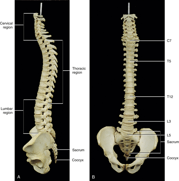
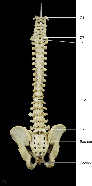
The first accurate description of the number of movable vertebrae in the fully developed spine was that of Galen between 100 and 200 ad (Shapiro, 1990). However, perhaps because of the many anatomic errors made by Galen in other areas, controversy ensued over the precise number of vertebrae until the publication of Vesalius’ De Humani Corporis Fabrica in 1543 (Shapiro, 1990). This publication showed that the human vertebral column develops into 24 vertebrae (Fig. 2-1), which are divided into 7 cervical, 12 thoracic, and 5 lumbar vertebrae (expressed as C1-7, T1-12, and L1-5, respectively). The L5 vertebra rests on the bony sacrum (made of five fused segments). The coccyx (three to five fused segments) is suspended from the sacrum. All of these bones are joined by means of a series of approximately 361 joints (including synovial, symphyses, and syndesmoses; and including the joints between the vertebrae and ribs and the joints associated with the sacrum and the coccyx) to form the vertebral column. See Appendix I for a detailed list of the joints of the vertebral column.
Curves of the Spine
The spine develops four anterior to posterior curves, two kyphoses, and two lordoses. (See introduction of text for further clarification of the terms lordosis and kyphosis.) Kyphoses are curves that are convex posteriorly (concave anteriorly), and lordoses are curves that are convex anteriorly (concave posteriorly). The two primary curves are the kyphoses. These include the thoracic and pelvic curvatures (see Fig. 2-1). They are called primary curves because they are seen from the earliest stages of fetal development. The thoracic curve extends from T2 to T12 and is created by the larger superior to inferior dimensions of the posterior portion of the thoracic vertebrae (see Chapter 6). The pelvic curve extends from the lumbosacral articulation throughout the sacrum to the tip of the coccyx. The concavity of the pelvic curve faces anteriorly and inferiorly, and is also caused by the greater superior to inferior dimensions of the posterior portion of the sacral segments.
The two secondary curves are the cervical lordosis and lumbar lordosis (see Fig. 2-1). These curves are known as secondary or compensatory curves because, even though they can be detected during fetal development, they do not become apparent until the postnatal period. The cervical lordosis begins late in intrauterine life but becomes apparent when an infant begins to lift his or her head from the prone position (approximately 3 to 4 months after birth). This forces the cervical spine into a lordotic curve. The cervical lordosis is further accentuated when the small child begins to sit upright and stabilizes his or her head while looking around in the seated position. This occurs at approximately 9 months of age. In the adult, the cervical curve is maintained by the larger superior to inferior dimensions of the anterior portion of the intervertebral discs. Because this curve is primarily created by the pliable intervertebral discs, traction of the cervical region reduces the cervical lordosis, whereas traction to the thoracic region has little effect on the thoracic kyphosis, because the thoracic curve is primarily created by the shape of the vertebrae. Further details of the cervical curvature are given in Chapter 5.
The action of the erector spinae muscles (see Chapter 4), pulling the lumbar spine erect to achieve the position necessary for walking, creates the posterior concavity known as the lumbar lordosis (see Fig. 2-1). Therefore the lumbar lordosis develops approximately 9 to 18 months after birth while the infant begins to walk upright. The lumbar lordosis extends from T12 to the lumbosacral articulation and is more pronounced in females than in males. The region between L3 and the lumbosacral angle is more prominently lordotic than the region from T12 to L2. After infancy, the lumbar lordosis is maintained by a combination of the shape of the intervertebral discs and the shape of the vertebral bodies. Each of these structures is taller anteriorly than posteriorly in the lumbar region of the spine. Therefore the lumbar lordosis is reduced when traction forces are applied to it, but the reduction is less than that found during traction of the cervical region.
A slight lateral curve normally is found in the upper thoracic region. The convexity of the curve is on the left in left-handed people and on the right in right-handed people. Such deviations are probably the result of asymmetric muscle use and tone.
The lumbar lordosis and thoracic kyphosis both increase from the supine to the standing position (Wood et al., 1996). In addition, the cervical lordosis has been found to compensate for the variations in lumbar lordosis that occur during changes in position and during normal motion. For example, lumbar lordosis increases during sitting in the erect position and cervical lordosis decreases during this activity. Lumbar lordosis decreases during lumbar forward flexion and cervical lordosis increases during lumbar flexion, and the opposite occurs during lumbar extension (Black, McClure, & Polansky, 1996).
The kyphoses and lordoses of the spine, along with the intervertebral discs, help to absorb the loads applied to the spine. These loads include the weight of the trunk, along with loads applied through the lower extremities during walking, running, and jumping. In addition, loads are applied by the carrying of objects with the upper extremities, by the pull of spinal muscles, and by the wide variety of movements that normally occur in the spine. The spinal curves, acting with the intervertebral discs and vertebral bodies, dissipate the increased loads that would occur if the spine were shaped like a straight column. Yet even with these safeguards, the vertebrae can be fractured as a result of the person falling and landing on the feet or buttocks, objects falling and landing on the head, or the person diving and landing on the head. Such injuries usually compress the vertebral bodies. Cervical compression usually occurs between C4 and C6 (Croft, 2009). When the force emanates from below, T9 through L2 are the most commonly affected through compression. Flexion injuries also can result in a compression fracture of vertebral bodies. Again, C4 through C6 are the most commonly affected in the cervical region, whereas T5 and T6 and the upper lumbar vertebrae usually are affected in the thoracic and lumbar regions (White & Panjabi, 1990).
Anatomy of a Typical Vertebra
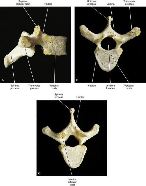
A typical vertebra can be divided into two basic regions: a vertebral body and a vertebral arch (also called the posterior arch or dorsal arch). The bone in both regions is composed of an outer layer of compact bone and a core of trabecular bone, also known as cancellous, or spongy, bone (Fig. 2-2). The cancellous bone is composed of myriad spicules of bone, known as trabeculae (singular, trabecula). The trabeculae are oriented parallel to the lines of greatest stress (Skedros, Mason, & Bloebaum, 1994; Skedros et al., 1994). Smit and colleagues (1997) found that the trabecular architecture of the lumbar vertebral bodies was ideal for the loads placed on the spine during axial compression (loads placed on the vertebral bodies from above; for example, to resist gravity) and walking. That is, not only were the trabeculae arranged to withstand axial compression, but also they were quite strong where the pedicles of the posterior arch met the vertebral bodies. This latter finding is consistent with the transfer of loads from the articular processes of the posterior arch to the vertebral bodies during rotational movements in the horizontal plane, and anterior to posterior (“shearing”) movements (most closely associated with walking).
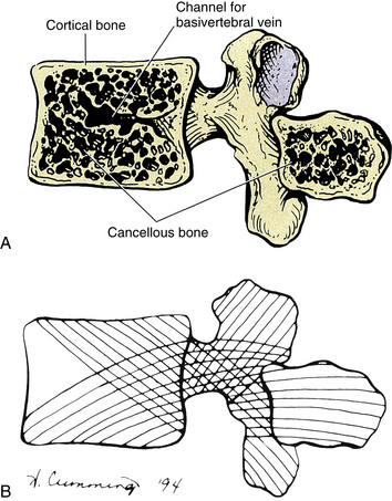
FIG. 2-2 Midsagittal view of a vertebra. A, The central cancellous, or trabecular, bone of the vertebral body and spinous process. Also notice the more peripheral cortical bone. B, The pattern of trabeculation, which develops along the lines of greatest stress.
The shell of compact bone is thin on the discal surfaces of the vertebral body and is thicker in the vertebral arch and its processes. The outer compact bone is covered by a thin layer of periosteum that is innervated by nerve endings, which transmit both nociception and proprioception (Edgar & Ghadially, 1976). The outer compact bone also contains many small foramina to allow passage for numerous veins and nutrient arteries. The trabecular interior of a vertebra contains red marrow and the vertebral bodies contain one or two large canals for the basivertebral vein(s).
The density of bone in the vertebrae varies from individual to individual but seems to increase significantly in most people during puberty and reaches a peak during the mid-twenties, when closure of the growth plates of the secondary centers of ossification occurs (Gilsanz, 1988; Gilsanz et al., 1988). A decrease in bone mineral density to below normal limits is known as osteoporosis. Osteoporosis also is accompanied by a rearrangement of the trabeculae within the spongy bone (Feltrin et al., 2001). This condition is of particular clinical relevance in the spine because of the weight-bearing function of this region. A decrease in bone mineral density and a rearrangement of trabeculae lead to a loss of elasticity in the bone and an increase in bone fragility. These changes, in turn, increase the likelihood of vertebral fracture (Mosekilde & Mosekilde, 1990; Feltrin et al., 2001). Osteoporosis has been associated with aging (Mosekilde & Mosekilde, 1990) and particularly with menopause (Ribot et al., 1988). Ribot and colleagues (1988) found that spinal bone density in French women remained stable in the young adult years and in women more than 70 years of age. An average rate of apparent bone loss of approximately 1% per year was found between the ages of 45 and 65. This represented approximately 75% of the total bone loss occurring within the individuals of their sample population (510 women). Ribot and colleagues (1988) also found that the bone mineral density in their population of French women appeared to be between 5% and 10% lower than reported values in the United States. Mosekilde and Mosekilde (1990), studying the L2 and L3 vertebrae, found relatively few sex-related differences in vertebral body density. However, Mosekilde (1989) did find a sex-related difference in vertebral trabecular architecture with age. Consistent with the findings of Ribot and colleagues (1988), Mosekilde (1989) discovered that in both sexes bone density diminished by 35% to 40% from 20 to 80 years of age. She also determined that the trabecular center (cancellous bone) of the vertebral body lost more bone mass than the outer cortical rim.
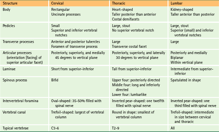
The regions of the vertebral body and vertebral arch are discussed separately in the following sections of this chapter. Elaboration on each component of the vertebra, with special emphasis placed on the characteristics unique to each region of the vertebral column, is included in the chapters on the cervical, thoracic, and lumbar regions of the spine (Chapters 5 through 7). In addition, Table 2-1 compares and contrasts the different parts of cervical, thoracic, and lumbar vertebrae.
Vertebral Body
The vertebral body (Fig. 2-3) is the large anterior portion of a vertebra that acts to support the weight of the human frame. Each vertebral body is designed to provide the greatest amount of strength with the least amount of bone mass (Feltrin et al., 2001). The vertebral bodies are connected to one another by fibrocartilaginous intervertebral discs, and when the bodies are combined with their intervening discs, they create a flexible column or pillar that supports the weight of the trunk and head. The vertebral bodies also must be able to withstand additional forces from contraction of the axial and proximal limb muscles. The bodies are cylindric in shape and have unique characteristics in each named region of the spine. The transverse diameter of the vertebral bodies increases from C2 to L3. This probably results from the fact that each successive vertebral body carries a slightly greater load. There is variation in the width of the last two lumbar vertebrae, but the width steadily diminishes from the first sacral segment to the apex (inferior tip) of the coccyx.
Vertical trabeculae predominate in the vertebral bodies. The vertical trabeculae are supported by horizontal trabeculae that function much like the struts or support beams in the frame of a building. Animal studies have shown that both the vertical and the horizontal trabeculae of a vertebral body increase in number after prolonged (weeks) and increased loading by superior-inferior compression (Issever et al., 2003).
Osteoporosis is associated with a decrease in mass primarily of the horizontal trabeculae, leaving less support for the vertical trabeculae when loads are placed on an osteoporotic vertebral body. This lack of horizontal support results in a weakening of the vertebral body beyond that anticipated by the percent reduction in bone mineral content. In fact, a 25% reduction in bone mass is accompanied by a 50% reduction in the ability of a vertebral body to resist loads applied to the spine.
Bone mineral density can vary significantly from one vertebra to another (Curylo et al., 1996). Although determining the presence or absence of osteoporosis by means of x-ray bone densitometry to measure bone mineral density is reliable, fractal analysis of the trabecular pattern within vertebral bodies as imaged by computed tomography (CT) also shows promise (Kim and Nah, 2007).
The vertebral bodies have been found to change (remodel) after degeneration of the intervertebral discs, by adding bone to the region adjacent to the intervertebral disc. This addition of bone is known as subchondral sclerosis, and allows the vertebral bodies to more effectively absorb the additional compressive loads received by the vertebral bodies after intervertebral disc degeneration (Moore et al., 1996a,b).
Mosekilde and Mosekilde (1990) found that the cross-sectional area of vertebral bodies is larger in men than in women. They also found that the cross-sectional area of the vertebral body increases with age in men, but no similar finding was discovered in women.
The superior and inferior surfaces of vertebral bodies range from flat, but not parallel (Standring et al., 2008), to interlocking (see Chapter 5). A raised, smooth region around the edge of the vertebral body is formed by the anular apophysis. The superior and inferior surfaces of the vertebral body are rougher inside the anular apophyses.
Most vertebral bodies are concave posteriorly (in the transverse plane), where they help to form the vertebral foramina. Small foramina for arteries and veins appear on the front and sides of the vertebral bodies. Posteriorly there are small arterial foramina and one or two large, centrally placed foramina for the exiting basivertebral vein(s) (Standring et al., 2008).
A series of relatively large arteries pierce the center of the vertebral bodies along their entire circumference (Fig. 2-4). On entering a vertebral body, these large nutrient arteries form a dense plexus of arteries within the central horizontal plane of the vertebral body. From this central plexus, many small branches ascend and descend to reach the superior and inferior margins of the vertebral bodies; these margins are adjacent to the cartilaginous end plates of the intervertebral discs.
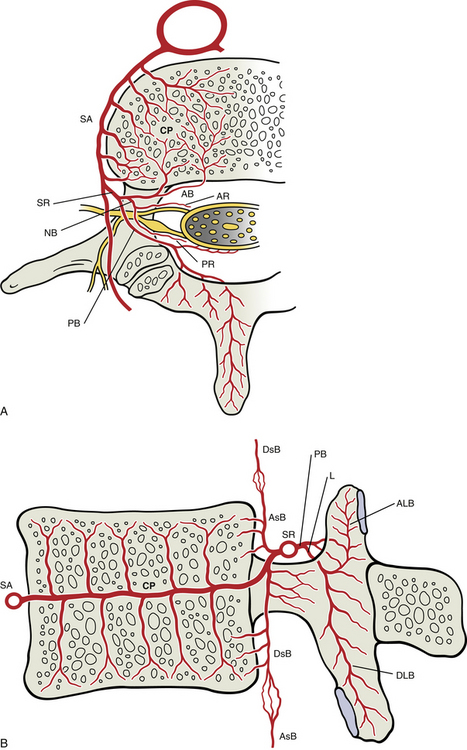
FIG. 2-4 Arterial supply to a typical vertebra and related tissues. A, Superior view of a horizontal section through the level of the vertebral body showing a lumbar segmental artery (SA) branching from the abdominal aorta and sending many branches to feed the dense central plexus (CP) of arteries formed within this plane of the vertebral body. From this central plexus many small branches ascend and descend to reach the superior and inferior margins of the vertebral bodies (see panel B). Also, notice that the spinal ramus of the segmental artery (SR) forms an anterior branch (AB) to the vertebral body and anterior tissues of the vertebral canal, a posterior branch (PB) to the posterior arch structures and posterior tissues of the vertebral canal, and a neural branch (NB) that divides into anterior (AR) and posterior (PR) radicular arteries to feed the ventral and dorsal roots (and rootlets), respectively. B, Midsagittal section showing the superior and inferior branches of the central arterial plexus of the vertebral body. These branches feed the arterial plexuses located subjacent to the cartilaginous end plates. Also notice that the anterior branch (not labeled here) of the spinal ramus provides an artery to the center of the vertebral body that helps supply the central arterial plexus as well. The anterior branch also produces an ascending (AsB) and a descending (DsB) branch, each of which anastomoses with a corresponding artery of adjacent vertebral levels. The posterior branch of the spinal ramus is shown dividing into a large laminar artery (L) that enters the lamina and then provides ascending (ALB) and descending (DLB) laminar branches to supply the superior and inferior articular processes, respectively, including the subchondral bone of the articular facets. See Arterial Supply to the Spine for further details.
Large numbers of small veins drain the superior and inferior margins of the vertebral bodies. These very small veins enter into large tributaries that are oriented in the horizontal plane very close to each superior and inferior vertebral margin. These large tributaries have been called the horizontal subarticular collecting vein system (Crock & Yoshizawa, 1976). Branches of the horizontal subarticular collecting vein system, in turn, drain into large, vertically oriented channels that course toward the central horizontal plane of the vertebral body, where a dense venous network is formed. The dense network is drained by the basivertebral vein (occasionally there are two basivertebral veins in the same vertebral body). The subarticular collecting vein system also sends small tributaries laterally. These small tributaries leave the vertebral body and drain into veins of the external vertebral venous plexus (see later information).
Items of Clinical Significance: Of clinical interest are the findings of Esses and Moro (1992), who found that long-term intraosseous hypertension within the vessels of the vertebral bodies is associated with an increase of pain and severity of osteoarthritis.
Occasionally a vertebral body compression fracture occurs some time (days to years) after an individual suffers trauma to the spine. This condition is known as “delayed posttraumatic vertebral collapse,” or Kümmell disease, and is probably the result of damage to the nutrient arteries of the vertebral body during the original injury. Damage to the nutrient arteries then leads to necrosis (ischemic necrosis) of the vertebral body and subsequent vertebral collapse (Van Eenenaam & El-Khoury, 1993).
Osteophytes of the vertebral bodies are protrusions of the superior or inferior aspects of the vertebral bodies that are composed of compact bone and extend toward the adjacent intervertebral disc and vertebral body. Anterior osteophytes of the vertebral bodies generally are more common than posterior ones and usually are larger. A large proportion of vertebral columns have osteophytes by the second decade of life, and by the fourth decade osteophytes are present in almost 100% of vertebral columns. The size of the osteophytes increases with age. There is no significant difference between osteophyte formation on the anterior aspect of the vertebral bodies and gender; however, males have more anterior osteophytes than females. Osteophytes on the posterior aspect of the vertebral bodies are most common in the lower cervical and lower lumbar regions and are more common in white than in black males and females. No significant difference exists in the prevalence of posterior osteophytes between males and females of the same racial background (Nathan, 1962).
Osteophytes develop slightly earlier in life in the thoracic and lumbar regions than in the cervical and sacral regions. However, in the fifth decade cervical osteophytes develop more rapidly than in the other regions of the spine, and by the seventh decade the incidence is nearly equal among cervical, thoracic, and lumbar osteophytes; osteophytes of the sacral region (only found on the first sacral segment) are the least common (Nathan, 1962).
Anterior osteophytes can result in complete interbody fusion. Such fusion is most common in the mid- to lower-thoracic region and in the lower-cervical region; however, fusion is extremely rare between C7 and T1 and between L5 and the first sacral segment (Nathan, 1962).
Osteophytes are much less common in the region of a vertebral body in contact with the aorta, and they usually develop in the region of the vertebral body that receives the greatest compressive loads during normal stance or common movements. For example, osteophytes tend to develop on the concave side of the normal curves of the spine. Anterior osteophytes, which generally are the most numerous, are most common in the thoracic region, and posterior osteophytes are most common in the cervical and lumbar regions of the spine (Nathan, 1962).
Bony End Plates
The ring apophyses, also known as the ring epiphyses, are secondary centers of ossification that develop along the periphery of the superior and inferior aspects of the vertebral bodies before puberty (see Chapter 12). These regions fuse with the remainder of the vertebral bodies usually by the age of 25 years. Some authors refer to the superior- and inferior-most regions of the vertebral body, including the area associated with the superior and inferior ring apophyses (both before and after their fusion with the remainder of the vertebral body), as the vertebral end plates. However, this terminology is confusing because the vertebral end plates (also known as the cartilaginous end plates) refer to the parts of each intervertebral disc that are found superior and inferior to the nucleus pulposus and anulus fibrosus. Therefore the term “bony end plate” is used in this text to describe the superior- and inferior-most regions of the vertebral bodies. During the time of puberty these regions are also associated with the ring apophyses, and the term bony end plate applies to the region of the ring apophyses as well, both before and after their fusion with the remainder of the vertebral bodies. The term vertebral end plate, or cartilaginous end plate, is used in this text to refer to the superior and inferior aspects of each intervertebral disc.
The central region of each bony end plate has a mottled appearance from birth to 6 months of age. This appearance results from vascular markings (holes) formed by small blood vessels that at this early age extend to the cartilaginous end plate from deep within the vertebral body.
Between 6 months and 2.5 years of age the mottled appearance of the central bony end plate diminishes (as the blood vessels disappear), and the end plate retains this somewhat smoother appearance for the remainder of the life of the vertebra. However, between 6 months and 25 years of age the peripheral margins of the end plates become prominently scalloped, showing prominent ridges and sulci. This scalloping results in a denticulate, or toothlike, appearance along the vertebral margins, having an appearance similar to that of the outer margins of the epiphyseal plates of other bones of the body. The scalloping of the bony end plate is variable from one vertebra to the next and is most prominent in the lower thoracic and upper lumbar regions, and less pronounced in the cervical and thoracic regions. The scalloping is thought to increase stability during the application of shear forces to the spine (forces that tend to slide one vertebra over the vertebra immediately inferior to it). Resistance to shear forces also explains why the scalloping is less prominent in the majority of the thoracic region and the entire cervical region, where the ribs and uncinate processes (see Chapter 5), respectively, resist shear forces in these areas. The ridges and sulci of the bony end plates become more prominent until approximately 12 to 25 years of age when the bone from the anular apophysis is laid down, creating an enlarging smooth ridge of bone that follows the peripheral margins of the superior and inferior surfaces of the vertebral bodies (Edelson & Nathan, 1988). The cortical bone of the central region of the superior and inferior bony end plates (i.e., the region of each end plate adjacent to the nucleus pulposus) is thinnest, and the end plates increase in thickness from this central region to the periphery (Grosland & Goel, 2007). Consequently, the periphery of the bony end plates can withstand more loads before failure than the more central regions of the end plates (Bailey et al., 2011).
Items of Clinical Significance: Beginning in the latter aspect of the third decade, osteophytes develop on the vertebral bodies, usually just adjacent to the bony end plate. That is, an osteophyte usually spares the bony end plate (there is usually a distinct sulcus between each osteophyte and the related bony end plate). The osteophytes then arch across the bony end plate, extending toward the adjacent vertebra (Edelson & Nathan, 1988).
Osteoporotic changes also can occur in the bony end plate. These changes usually begin toward the end of the fifth decade and progress until death. Osteoporotic changes in the bony end plates assume the appearance of lytic, or “punched out,” areas of the bone (Edelson & Nathan, 1988).
Vertebral Arch
The vertebral (posterior) arch has several unique structures (see Fig. 2-3). These include the pedicles, laminae, and superior articular, inferior articular, transverse, and spinous processes. Each of these subdivisions of the vertebral arch is discussed separately in the following sections.
Pedicles
The pedicles (see Fig. 2-3) create the narrow anterior portions of the vertebral arch. They are short, thick, and rounded and attach to the posterior and lateral aspects of the vertebral body. They also are placed superior to the midpoint of a vertebral body. Because the pedicles are smaller than the vertebral bodies, a groove, or vertebral notch, is formed above and below the pedicles. These are known as the superior and inferior vertebral notches, respectively. The superior vertebral notch is more shallow and smaller than the inferior vertebral notch.
The percentage of compact bone surrounding the inner cancellous bone of the pedicles varies from one region of the spine to another and seems to depend on the amount of motion that occurs at the given region (Pal et al., 1988). More compact, stronger bone is found in regions with more motion. Therefore the pedicles of the middle cervical and upper lumbar regions contain more compact bone than the relatively immobile thoracic region. The thoracic pedicles are made primarily of cancellous bone (Pal et al., 1988).
There are significant differences in the relative size of various parts of vertebrae among various ethnic populations, with those from Western populations generally having larger structures than those from Asia. This is true for the pedicles (Chadha et al., 2003).
Laminae
The laminae (singular, lamina) are continuous with the pedicles. They are flattened from anterior to posterior and form the broad posterior portion of the vertebral arch (see Fig. 2-3). They curve posteromedially to unite with the spinous process, completing the vertebral foramen. Xu and colleagues (1999) performed a detailed morphometric study of the laminae of the entire vertebral column. They concluded that, generally speaking, the laminae of males are slightly larger than those of females. The laminae generally increase in height from C4, which are the shortest (10.4 ± 1.1 mm), to T11, which are the tallest (25.1 ± 2.5 mm). The height of the laminae then begin to decrease slowly from T12 to L4, and then more markedly at L5. However, the laminae are widest at L5 (15.7 ± 2.0 mm) and narrowest at T4 (5.8 ± 0.8 mm). The cervical laminae are wide (rivaling those of L5), the thoracic laminae (with the exception of T11 and T12) are narrow, and the width steadily increases from T11 to L5. The laminae are thickest at T2 (5.0 ± 0.2 mm) and least thick at C5 (1.9 ± 0.6 mm), with the thickness of the laminae decreasing from the upper to the lower thoracic regions. The lower cervical laminae are the least thick of the vertebral column, and the lumbar laminae are of intermediate thickness (Xu et al., 1999).
Spinous Process
The spinous process (spine) of each vertebra (see Fig. 2-3) projects posteriorly and often inferiorly from the laminae. The size, shape, and direction of this process vary greatly from one region of the vertebral column to the next (see individual regions). A spinous process also may normally deviate to the left or right of the midline, and this can be a source of confusion in clinical practice. Therefore a deviated spinous process seen on x-ray film or palpated during a physical examination frequently is not associated with a fracture of the spinous process or a malposition of the entire vertebra.
The spinous processes throughout the spine function as a series of levers both for muscles of posture and for muscles of active movement (Standring et al., 2008). Most of the muscles that attach to the spinous processes act to extend the vertebral column. Some muscles attaching to the spinous processes also rotate the vertebrae to which they attach.
Lateral to the spinous processes are the vertebral grooves. These grooves are formed by laminae in the cervical and lumbar regions. They are much broader in the thoracic region and are formed by both the laminae and transverse processes. The left and right vertebral grooves serve as gutters. These gutters are filled with the deep back muscles that course the entire length of the spine.
The spinous process of a specific vertebra frequently can be identified by its relationship to other palpable landmarks of the back. Chapter 1 provides a detailed account of the relationship between the spinous processes and other anatomic structures.
Vertebral Foramen and the Vertebral Canal
The vertebral foramen is the opening within each vertebra that is bounded by the structures discussed thus far. Therefore the vertebral body, the left and right pedicles, the left and right laminae, and the spinous process form the borders of the vertebral foramen in a typical vertebra (see Fig. 2-3). The size and shape of the vertebral foramina vary from one region of the spine to the next and even from one vertebra to the next. The vertebral canal is the composite of all of the vertebral foramina. This region houses the spinal cord, nerve roots, meninges, and many vessels. The vertebral canal is discussed in more detail later in this chapter.
Transverse Processes
The transverse processes project laterally from the junction of the pedicle and lamina (pediculolaminar junction) (see Fig. 2-3). Like the spinous processes, their exact direction varies considerably from one region of the spine to the next. The transverse processes of typical cervical vertebrae project obliquely anteriorly between the sagittal and coronal planes and are located anterior to the articular processes and lateral to the pedicles. The left and right cervical transverse processes are separated from those of the vertebrae above and below by successive intervertebral foramina. The thoracic transverse processes are different and project obliquely posteriorly and are located behind the articular processes, pedicles, and intervertebral foramina (see Fig. 6-1). They also articulate with the ribs. The lumbar transverse processes (see Fig. 7-2) lie in front of the lumbar articular processes and posterior to the pedicles and intervertebral foramina.
The transverse processes serve as muscle attachment sites and are used as lever arms by spinal muscles. The muscles that attach to the transverse processes maintain posture and induce rotation and lateral flexion of single vertebrae and the spine as a whole.
Each transverse process is composed of the “true” transverse process (diapophysis) and a costal element. Each costal element (pleurapophysis) develops as part of the neural arch (see Fig. 12-13). The costal elements of the thoracic region develop into ribs. Elsewhere the costal elements are incorporated with the diapophysis and help to form the transverse process of the fully developed vertebra. The cervical costal elements are composed primarily of the anterior tubercle but also include the intertubercular lamella and a part of the posterior tubercle. The lumbar costal elements are the anterior aspects of the transverse processes, and the left and right sacral alae represent the costal processes of the sacrum. The cervical and lumbar costal processes occasionally may develop into ribs. This occurs most frequently in the lower cervical and upper lumbar regions. These extra ribs may be a cause of discomfort in some individuals. This is particularly true of cervical ribs (see Chapter 5).
Superior Articular Processes
Like the transverse processes, the superior articular processes (zygapophyses) and facets also arise from the pediculolaminar junction (see Fig. 2-3). The left and right superior articular processes project superiorly, and the articular surface (facet) of each articular process faces posteriorly, although the precise direction varies from posteromedial in the cervical and lumbar regions to posterolateral in the thoracic region. (The superior and inferior articular facets are discussed in more detail later in this chapter under Zygapophysial Joints.)
Inferior Articular Processes
The left and right inferior articular processes (zygapophyses) and facets project inferiorly from the pediculolaminar junction, and the articular surface (facet) faces anteriorly (see Fig. 2-3). Again, the precise direction in which they face varies from anterolateral (cervical region) to anteromedial (thoracic and lumbar regions).
Adjoining zygapophyses form zygapophysial joints (Z joints), which are small and allow for limited movement. Mobility at the Z joints varies considerably between vertebral levels. The Z joints also help to form the posterior border of the intervertebral foramina. The anatomy of the Z joint is discussed after the next section.
Functional Components of a Typical Vertebra
Each region of a typical vertebra is related to one or more of the functions of the vertebral column mentioned at the beginning of this chapter (support, protection of the spinal cord and spinal nerve roots, and movement) (Fig. 2-5). In general, the vertebral bodies help with support, whereas the pedicles and laminae protect the spinal cord. The superior and inferior articular processes help determine spinal movement by the facing of their facets. The transverse and spinous processes aid movement by acting as lever arms on which the muscles of the spine act.
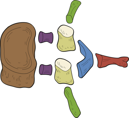
FIG. 2-5 Functional components of a typical vertebra. The vertebral body (brown) serves the function of support. The pedicles (purple) and laminae (blue) serve the function of protection of the spinal cord (cervical and thoracic regions) or cauda equina (below the level of L1). The spinous process (red), transverse processes (dark green), articular processes (tan), and particularly the articular facets (cream) serve the function of movement (see text).
The posterior arches also function to support and transfer weight (Pal et al., 1988), and the articular processes of the cervical region form two distinct pillars (left and right) that bear weight. In addition, the laminae of C2, C7, and the upper thoracic region (T1 and T2) help to support weight. Therefore a laminectomy at these levels results in marked cervical instability (Pal et al., 1988), whereas a laminectomy from C3 to C6 is relatively safe.
The pedicles also act to transfer weight from the posterior arch to the vertebral body, and vice versa in the cervical region (Pal et al., 1988), but only from the posterior arch to the vertebral bodies in the thoracic region. The role of the pedicles in the transfer of loads is yet to be completely determined in the upper lumbar region, but the trabecular pattern of the L4 and L5 pedicles seems to indicate that the majority of load may be transferred from the vertebral bodies to the region of the posterior arch in these two vertebrae. This is discussed in further detail in Chapter 7, which is devoted to the lumbar spine.
Zygapophysial Joints
The articulating surface of each superior and inferior articular process (zygapophysis) is covered with a 1- to 2-mm-thick layer of hyaline cartilage. This hyaline-lined portion of a superior and inferior articular process is known as the articular facet. The junction found between the superior and inferior articular facets on one side of two adjacent vertebrae is known as a zygapophysial joint. Therefore, a left Z joint and a right Z joint are between each pair of vertebrae. Figure 2-6, A, shows the Z joints of the cervical, thoracic, and lumbar regions. These joints also are called facet joints or interlaminar joints (Giles, 1992). The Z joints (Fig. 2-6, B to D) are classified as synovial (diarthrodial), planar joints. They are rather small joints, and although they allow motion to occur, they are perhaps more important in their ability to determine the direction and limitations of movement that can occur between vertebrae. In addition, the Z joints (more specifically, the articular processes) help to carry the loads placed on the spine, particularly during extension and rotation (Schultz et al., 1973). The Z joints are of added interest to those who treat spinal conditions because they have been found to be a source of back pain (Dreyer & Dreyfuss, 1996). Z joint pain may be generated as a result of direct injury to the joints, or as is the case with any synovial joint, loss of motion or aberrant motion of the Z joints may result in pain (Paris, 1983). In addition, degeneration of the hyaline cartilage that composes the articular facets can result in pain (Lewinnek & Warfield, 1986). In fact, the Z joints have been found to be a source of pain in 39% of chronic cervical pain patients, and in 34% and 27% of patients with chronic thoracic and lumbar pain, respectively (Manchukonda et al., 2007).
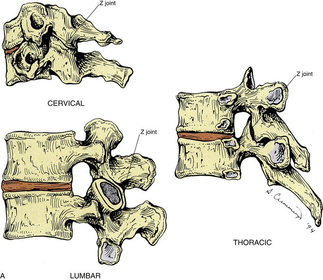
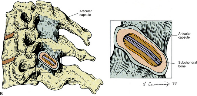
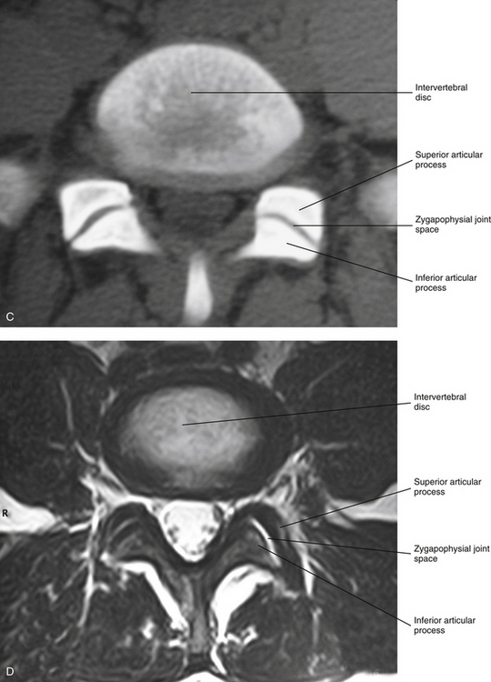
FIG. 2-6 A, Typical Z joints of each vertebral region. B, Typical Z joint. The layers of the Z joint as seen in parasagittal section (inset) are color coded as follows: light blue, joint space; violet, articular cartilage; brown, subchondral bone; orange, synovial lining of articular capsule; peach, vascularized, middle layer of the articular capsule; turquoise, fibrous, outer layer of the articular capsule. C, Horizontal computed tomography (CT) showing lumbar Z joints. D, Magnetic resonance imaging (MRI) scan through the left and right Z joints of typical lumbar vertebrae. (Images courtesy Dr. Dennis Skogsbergh.)
Each Z joint is surrounded posterolaterally by a capsule. The outer capsule and inner layers of the capsule differ significantly in composition; this is possibly unique to Z joints (Yamashita et al., 1996). The capsule consists of an outer layer of dense fibroelastic connective tissue, a vascular central layer made up of areolar tissue and loose connective tissue, and an inner layer consisting of a synovial membrane (Giles & Taylor, 1987). Figure 2-6, B, shows the previously listed regions of the capsule. The anterior and medial aspects of the Z joint are covered by the ligamentum flavum. The synovial membrane lines the articular capsule, the ligamentum flavum (Xu et al., 1991), and the synovial joint folds (see the following), but not the hyaline articular cartilage that covers the joint surfaces of the articular processes (Giles, 1992).
The Z joint capsules throughout the vertebral column are thought to do little to limit motion (Onan, Heggeness, & Hipp, 1998), although the capsules probably help to stabilize the Z joints during motions (Boszczyk et al., 2001).
Generally, the Z joint capsules are relatively thin and loose and are attached to the margins of the opposed superior and inferior articular facets of the adjacent vertebrae (Standring et al., 2008). Superior and inferior external protrusions of the joint capsules, known as recesses, bulge from the joint and are filled with adipose tissue. The inferior recess is larger than the superior one (Jeffries, 1988). The capsules are longer and looser in the cervical region than in the lumbar and thoracic regions.
Innervation of the Zygapophysial Joints
The Z joint capsule receives significant sensory innervation (Cavanaugh, Kallakuri, & Özaktay, 1995; Vandenabeele, Creemers, & Lambrichts, 1996). Ahmed and colleagues (1993) found both sensory and autonomic fibers in the synovial layer of the Z joint capsules of rats. They also found evidence of nociceptive innervation in the ligamentum flavum proper (that portion of the ligamentum flavum adjacent to the Z joint). The authors concluded that both sensory and autonomic innervations could play a collaborative role in the pathophysiology of Z joint pain, inflammation, and inflammatory joint disease.
The sensory nerve supply to each Z joint (Fig. 2-7) is derived from the medial branch of the posterior primary division (dorsal ramus) at the level of the joint, and each joint also receives innervation from the medial branch of the posterior primary division of the level superior and the level inferior (Jeffries, 1988). This multilevel innervation is probably one reason why pain from a Z joint frequently has a very broad referral pattern (Jeffries, 1988). Chapters 5, 6, and 7 describe features unique to innervation of the cervical, thoracic, and lumbar Z joints, respectively; and Chapter 11 discusses the phenomenon of referred pain in more detail.
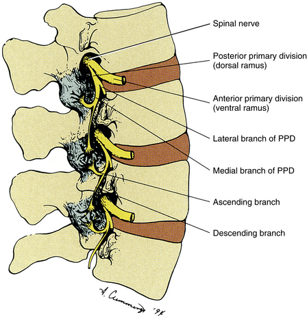
FIG. 2-7 Innervation of the Z joints. Each spinal nerve divides into a medial and a lateral branch. The medial branch has an ascending division, which supplies the Z joint at the same level, and a descending division, which supplies the Z joint immediately below. Jeffries (1988) states that each lumbar medial branch also sends a branch to the Z joint of the level above (not shown in illustration). PPD, Posterior primary division.
The medial branches of the posterior primary divisions innervating a Z joint terminate as one of three types of sensory receptors: free nerve endings (nociceptive), complex-unencapsulated nerve endings, and encapsulated nerve endings (Yamashita et al., 1990; Beaman et al., 1993; Cavanaugh, Kallakuri, & Özaktay, 1995). The latter two types are thought to be associated with proprioceptive sense and the modulation of protective muscular reflexes. The free nerve endings are associated with nociception (i.e., signaling potential or real tissue damage). The ultrastructure of these receptors has been described (Vandenabeele et al., 1997; McLain & Pickar, 1998).
In addition, Wyke (1985) categorized the types of sensory receptors in Z joints by their function. These categories are as follows:
• Type I: Very sensitive static and dynamic mechanoreceptors that fire continually, even to some extent when the joint is not moving
• Type II: Less sensitive mechanoreceptors that fire only during movement
• Type III: Mechanoreceptors found in joints of the extremities (Wyke [1985] did not find these in the Z joints.)
Wyke (1985) asserts that type I and II receptors have a pain suppressive effect (a Melzack and Wall gate control type of mechanism). He also states that there is a reflexogenic effect created by type I and II fibers that causes a normalization of muscle activity on both sides of the spinal column when stimulated. This reflexogenic effect is thought to occur at the level of the site of stimulation, as well as at the levels superior and inferior to this site. Of possible interest is the fact that Isherwood and Antoun (1980) found similar nerve endings within the interspinous and supraspinous ligaments and the ligamentum flavum. These ligaments are respectively discussed in Chapters 5 and 6 on the cervical and thoracic regions.
Innervation by mechanoreceptors is denser in the cervical Z joint capsules than in those of the thoracic and lumbar regions (McLain, 1994; McLain & Pickar, 1998). This may be because the increased mobility of the cervical region may require more proprioceptive input to ensure smooth and accurate head movement and positioning, and also to help prevent injury from inappropriate motions or muscle responses to sudden movements. Innervation by free nerve endings associated with nociception is abundant in all regions of the spine (McLain & Pickar, 1998).
Beaman and colleagues (1993) found nerves that stained with substance P (associated with pain) in the bone underlying the articular facets of the articular processes (subchondral bone) from specimens of Z joints taken during surgical procedures of patients with low back pain and accompanying degeneration of the Z joints, but not in control specimens. This indicates that the subchondral bone may be an additional source of pain in individuals with arthritis of the spine (including degenerative joint disease, also known as osteoarthritis, or common degenerative arthritis) or with injury to the spine. Because degeneration of the spine can result in an increase in the loads placed on the Z joints by 3% to 47%, depending on the severity of the degeneration, the presence of nociceptive (pain) nerve endings in the subchondral bone of the Z joint articular facets indicates that the subchondral bone in this region may play an active role in back pain. The combined innervation of the Z joint capsules and subchondral bone provides further strong evidence implicating the Z joints as an important source of back pain in many individuals.
Zygapophysial Joint Synovial Folds
Z joint synovial folds are synovium-lined extensions of the capsule that protrude into the joint space to cover part of the hyaline cartilage. Although the function of the synovial folds has not been definitively determined, they are thought to provide lubrication to the Z joints, through the secretion of synovial fluid, and also to protect the margins of the articular cartilage (Uhrenholt et al., 2008). The synovial folds vary in size and shape in the different regions of the spine. Figure 2-8 shows a photomicrograph by Singer and colleagues (1990) demonstrating a large Z joint synovial fold. Chapters 5, 6, and 7 discuss the unique characteristics of Z joint synovial folds in the cervical, thoracic, and lumbar regions, respectively.
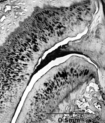
FIG. 2-8 A fibrous synovial fold is shown protruding between the articular surfaces of a Z joint. (From Singer K, Giles D, & Day R. [1990]. Intra-articular synovial folds of thoracolumbar junction zygapophysial joints, Anat Rec, 226, 147-152.)
Kos in 1969 described the typical intraarticular fold (meniscus) (Fig. 2-9) as being attached to the capsule by loose connective tissue. Synovial tissue and blood vessels were distal to the attachment, followed by dense connective tissue (Bogduk & Engel, 1984).
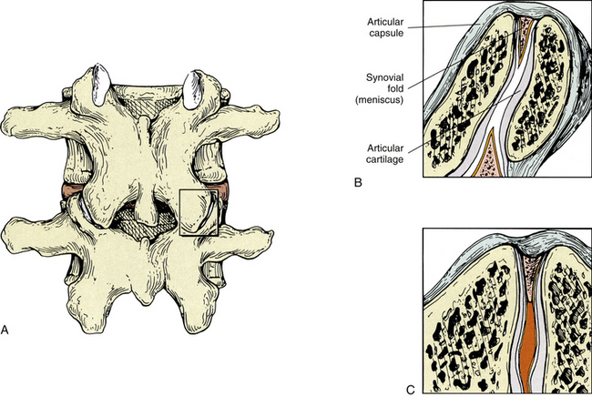
FIG. 2-9 Z joint synovial folds. A, Posterior view of the lumbar Z joint. B, A coronal section deep to that demonstrated in the box of A. This coronal section shows the Z joint synovial folds. Notice the synovial lining of these folds, the articular cartilage, and the joint space. The synovial fold is attached to the articular capsule. C, An entrapped synovial fold. The distal portion of the fold is fibrous, and the proximal portion contains vessels and adipose tissue. Giles and Taylor (1987) also have found sensory nerve endings within the Z joint synovial folds.
In 1982 Engel and Bogduk reported on a study of 82 lumbar Z joints. They found at least one intraarticular fold within each joint. The intraarticular structures were categorized into three types. The first was described as a connective tissue rim found running along the most peripheral edge of the entire joint. This connective tissue rim was lined by a synovial membrane. The second type of meniscus was described as an adipose tissue pad, and the third type was identified as a distinct, well-defined, fibroadipose meniscoid. This latter type of meniscus usually was found entering the joint from either the superior or the inferior pole or both poles of the joint.
Giles and Taylor (1987) studied 30 lumbar Z joints, all of which were found to have menisci. The menisci were renamed zygapophysial joint synovial folds because of their histologic composition. Free nerve endings were found within the folds, and the nerve endings met the criteria necessary for classification as pain receptors (nociceptors). That is, they were distant from blood vessels and were of proper diameter (0.6 to 12 µm). Therefore the synovial folds (menisci) themselves were found to be pain sensitive. This meant that if the Z joint synovial fold became compressed by, or trapped between, the articular facets making up the Z joint, back pain could result (see Fig. 2-9). Other investigators have confirmed the presence of sensory fibers in the Z joint synovial folds (Ahmed et al., 1993; Vandenabeele, Creemers, & Lambrichts, 1996).
Zygapophysial Joints as a Source of Back Pain
Various Clinical Approaches to Pain Management: Damage to the osseous and ligamentous tissues (including the capsule) of a Z joint can result in inflammation, which can cause the release of chemicals that stimulate the nociceptive nerve endings supplying the joint (Cavanaugh, Kallakuri, & Özaktay, 1995; Cavanaugh et al., 1996, 1997). Therefore not surprisingly, the Z joints have been shown to be a source of back pain (Mooney & Robertson, 1976; Lippitt, 1984; Jeffries, 1988; Beaman et al., 1993), and several therapeutic approaches have been designed to treat pain originating from the Z joints. Physical therapy in the form of ice, moist heat, or exercise is used frequently. Acupuncture also has been used. Injection of the Z joints with local anesthetic or corticosteroids is carried out with some frequency (Datta et al., 2009), and denervation of the Z joints has been performed by a number of clinicians and researchers (Shealy, 1975). Surgical transection of the posterior primary divisions innervating these joints was the first method used to denervate the joint. This technique has been replaced by radiofrequency neurotomy, which has been found to reduce neck and low back pain in carefully selected patients (Dreyfuss et al., 2000; Bogduk, 2005b). Initially, some researchers were not entirely convinced that this was the method of choice for treating pain arising from these structures (Lippitt, 1984), and damage to the medial branch of the posterior primary division during surgical laminectomy has been linked to prolonged postoperative pain, denervation atrophy of paraspinal back muscles, and functional instability that can extend beyond the segments involved in the surgical procedure (Sihvonen et al., 1993; Boelderl et al., 2002). However, more recent studies indicate that there is no long-term segmental muscular atrophy of paraspinal (multifidus) muscles following medial branch radiofrequency neurotomy (Dreyfuss et al., 2009).
Spinal adjusting (manipulation) to introduce movement into a Z joint suspected of being hypomobile also has been used frequently to treat pain of Z joint origin. Mooney and Robertson (1976) stated that spinal manipulation may produce therapeutic benefit by relieving the Z joint articular capsule or its synovial lining from chronic reaction to trauma. Such chronic reaction to trauma resulting in Z joint pain includes the catching of a synovial fold between the joint capsule and an articular process and also the entrapment of zygapophysial joint menisci (synovial folds) deep within the Z joint (see Fig. 2-9). Entrapped Z joint menisci may be a direct source of pain because they are supplied by pain-sensitive nerve endings (Giles & Taylor, 1987; Ahmed et al., 1993; Vandenabeele, Creemers, & Lambrichts, 1996). Spinal adjusting (manipulation) separates (gaps) the opposed articular surfaces of the Z joint (Cramer et al., 2000, 2002, 2012), and this separation may relieve direct pressure on the meniscus, and also provide traction to the Z joint articular capsule that, by its attachment to the Z joint meniscus, could pull the meniscus peripherally, away from the region of previous entrapment (Kos & Wolf, 1972). Bogduk and Engel (1984) felt that entrapment of a Z joint meniscus would tear it away from its capsular attachment. If this were the case, the nerve endings leading to the synovial fold probably would be torn as well. This could result in transient pain. Bogduk and Engel (1984) also stated that a meniscus that had torn away from its capsular attachment could conceivably result in a loose body being found in the Z joint, similar to those that are sometimes found in the knee. This, they felt, may be amenable to spinal manipulation. However, the frequency with which this scenario actually occurs in clinical practice was questioned (Bogduk & Engel, 1984). Further research is needed to clarify the frequency with which Z joint menisci (synovial folds) actually tear away from their capsular attachments to become loose bodies. Additional study also is needed to determine whether menisci can become entrapped while remaining attached to the capsule and their nerve supply.
Mooney and Robertson (1976) used facet joint injections of local anesthetic and corticosteroids to treat pain arising from the Z joint. They felt that such injections helped to relieve intraarticular adhesions that had been seen to develop during the degenerative phase of progressive back pain. Because hypomobility results in degenerative changes of the Z joints (Cramer et al., 2004), perhaps the removal of this type of adhesion could be another positive effect of Z joint manipulation.
Movement of the Spine
Movement between two typical adjacent vertebrae is slight, but when the movement between many segments is combined, the result is a great deal of movement. The movements that can occur in the spine include flexion, extension, lateral flexion (side bending), rotation, and circumduction (Fig. 2-10). Circumduction is a combination of flexion, lateral bending, rotation, and extension. The intervertebral discs help to allow and to limit the amount of movement that can occur between individual vertebrae. The thicker intervertebral discs of the cervical and lumbar regions allow for more movement to occur in these regions. In addition, the shape and orientation of the articular facets determine the movements that can occur between two adjacent segments and also limit the amount of movement that can occur between segments. Interestingly, the beginning and middle stages of degeneration (stages I through IV) of the intervertebral discs increase segmental motion, as the thinning discs allow more “joint play” between the segments. However, once end-stage degeneration is reached (stage V), segmental motion decreases. In addition, the early stages of degeneration of the Z joints (stages I through III; accompanied by erosion of the articular hyaline cartilage) increase rotation (axial rotation) of the spine. However, during the later stages of Z joint degeneration, additional bone is added to the subchondral bone subjacent to the Z joint hyaline cartilage articular facets. This process is known as subchondral sclerosis. Once subchondral sclerosis of the Z joints occurs, axial rotation of the involved segments of the spine decreases to below normal levels (Fujiwara et al., 2000).
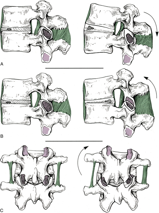
FIG. 2-10 Motion between adjacent vertebrae. A through C (left), Vertebrae in their neutral position. A (right), Vertebrae in extension. The anterior longitudinal ligament is becoming taut. B (right), Vertebrae in flexion. Notice that the interspinous and supraspinous ligaments, as well as the ligamentum flavum, are being stretched. C (right), Vertebrae in lateral flexion. The left intertransverse ligament is becoming taut, and the right inferior articular process is making contact with the right lamina.
The specific ranges of motion of the spine are discussed with each vertebral region (see Chapters 5 through 7). However, this section discusses the factors limiting spinal motion and the phenomenon of coupled motion.
The Role of Spinal Ligaments
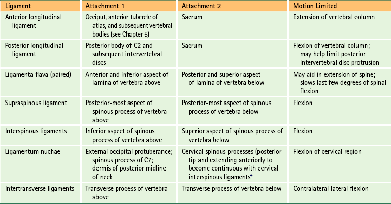
The ligaments of the spine are discussed from superior to inferior with the region in which they first occur (e.g., ligamentum nuchae and anterior longitudinal ligament with the cervical spine; supraspinous ligament with the thoracic spine). Thereafter, the ligaments are mentioned only when they have unique characteristics in a specific region. The intervertebral disc is covered later in this chapter. However, this section discusses some of the characteristics common to the majority of spinal ligaments. In addition, Tables 2-2 and 2-3 summarize the attachment sites and functions (motions restricted) of the most important ligaments of the spine.
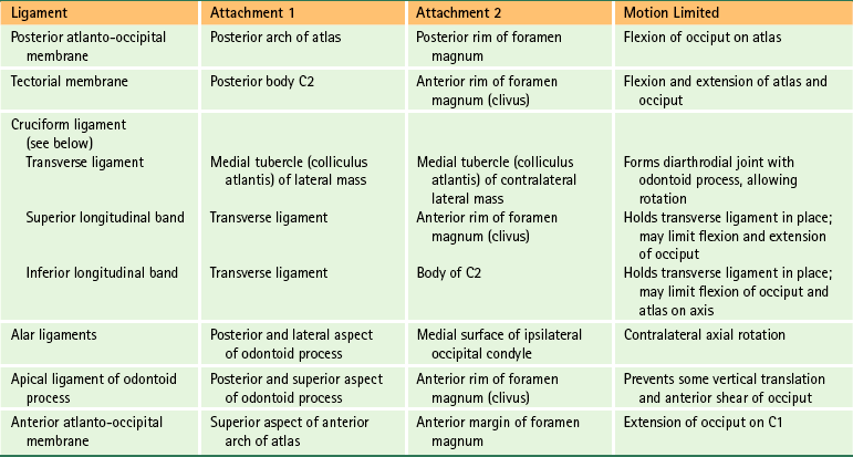
Table 2-3
Ligaments of the Lower Cervical, Thoracic, and Lumbar Regions∗
∗See Chapters 5 through 7 for further details.
The role of the spinal ligaments is to allow smooth motion, with the least amount of resistance and maximum conservation of energy, within the spine’s full normal range of motion. The ligaments also help to provide protection to the spinal cord, by limiting too much motion and absorbing a significant amount of the loads placed on the spine during trauma. The functional properties of a ligament are a combination of the physical properties of the ligament (as described by its load displacement curve; see the following) and also the orientation and location of the ligament with respect to the moving vertebrae.
The ligaments of the vertebral column are most effective in carrying loads along the direction in which their fibers run. They readily resist tensile forces but buckle when subjected to compression.
Although each ligament has a unique combination of stiffness, maximum deformation, and failure load, the similarities of the spinal ligaments with regard to these parameters are striking (i.e., biomechanically speaking, the load-deformation curves for all of the spinal ligaments are similar). For all ligaments of the spine, there is a sharp increase in stiffness once full physiologic motion has been attained (little stiffness up to the end of physiologic motion). Spinal degeneration generally leads to increased motion (in the initial stages). This increased motion can result in increased strain on the ligaments, which in turn can result in ligamentous sprain. Consequently, degenerated spines may carry higher risks for increased ligament sprains during flexion, extension, axial rotation, and lateral flexion.
Using nerve tracing techniques in an animal model, Jiang (1997) found that stretching of a spinal ligament resulted in “a barrage of sensory feedback from several spinal cord levels on both sides of the spinal cord.” The sensory information was found to ascend to many higher centers by way of the dorsal columns and spinocerebellar tracts (see Chapter 9). These higher centers included the thalamus and vestibular nuclei. Jiang’s (1997) findings provide provocative evidence that the spinal ligaments, along with the Z joint capsules and the small muscles of the spine (interspinales, intertransversarii, and transversospinales muscles), play an important role in mechanisms related to spinal proprioception (joint position sense). In addition, Solomonow and colleagues (1998) found that compression of the supraspinous ligament of cats or electrical stimulation of the same ligament in humans resulted in contraction of the multifidus muscle (see Chapter 4) at the same level as the stimulation and also at the segmental levels above and below the stimulation. These authors concluded that the ligaments of the vertebral column recruit the help of spinal muscles to achieve general spinal stability.
Structures That Limit Spinal Movement
Spinal motion is limited by a series of bony stops and ligamentous brakes (Louis, 1985). Table 2-4 shows some of the structures limiting spinal motion.
Table 2-4
Factors Limiting Spinal Motion
| Motion | Structures Limiting Motion |
| Flexion | Posterior longitudinal ligament Ligamenta flava Interspinous ligament Supraspinous ligament Posterior fibers of intervertebral disc Articular capsules Tension of back extensor muscles Anterior surface of inferior articular facet against posterior surface of superior articular facet |
| Extension | Anterior longitudinal ligament Anterior aspect of intervertebral disc Approximation of spinous processes, articular processes, and laminae |
| Lateral flexion | Contralateral side of intervertebral disc and intertransverse ligament Approximation of articular processes Approximation of uncinate processes (cervical region) Approximation of costovertebral joints (thoracic region) Antagonist muscles |
| Rotation | Tightening of lamellar fibers of anulus fibrosus Orientation and architecture of articular processes |
Compiled from Standring S et al. (2008). Gray’s anatomy: the anatomical basis of clinical practice (40th ed.). Edinburgh: Churchill Livingstone.
Other factors associated with each type of spinal motion include the following:
• Flexion: The anterior longitudinal ligament is relaxed and the anterior aspects of the discs are compressed. The intervals between laminae are widened; the inferior articular processes glide upward on the superior articular processes of the subjacent vertebrae. The lumbar and cervical regions allow for more flexion than the thoracic region (Standring et al., 2008).
• Extension: Motion is more restricted in the thoracic region because of thinner discs and the effects of the thoracic skeleton and musculature.
• Lateral flexion: Sides of the intervertebral discs are compressed. Lateral flexion is greatest in the cervical region, followed by the lumbar region, and finally the thoracic region (White & Panjabi, 1990).
Rotation with Lateral Flexion (“Coupled Motion”)
The main motions of flexion-extension, left and right axial rotation, and left and right lateral bending are accompanied by subtle motions of the vertebrae in the other directions. These subtle motions that attend the main motions of the spine are called “coupled motions.” Haher and colleagues (1992) defined coupled motion more precisely as “consistent association of one motion about an axis with another motion about a second axis.” Coupled motions are complex and vary from one vertebral segment to the next (Ochia et al., 2006). There is little consensus among investigators for many of the coupled motions. These motions are most predictable, and consensus among investigators is highest in the cervical and lumbar regions when the main motion is lateral flexion (Harrison, Harrison, & Troyanovich, 1998).
As a result of the facing of the superior and inferior articular facets, lateral flexion of the cervical and lumbar regions is accompanied by axial rotation (Fig. 2-11). These are coupled motions. However, the direction of the rotation is opposite in these two regions, and more rotation occurs with lateral flexion in the cervical than the lumbar region (Moroney et al., 1988). Lateral flexion of the cervical spine is accompanied by rotation of the vertebral bodies into the concavity of the arch formed by the lateral flexion (vertebral body rotation to the same side as lateral flexion). For example, right lateral flexion of the cervical region is accompanied by right rotation of the vertebral bodies (see Fig. 2-11, A). Because the spinous processes move in the direction opposite that of the vertebral bodies during rotation, right lateral flexion of the cervical region is accompanied by left rotation of the spinous processes.
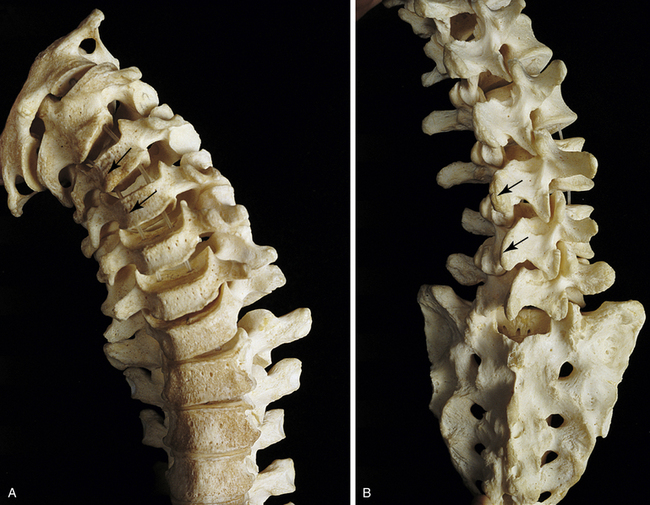
FIG. 2-11 Coupled motion. This phenomenon is seen best from the anterior view in the cervical region and the posterior view in the lumbar region. Notice that even though the arrows in A and B point in the same direction, the vertebral bodies are moving in the opposite direction, because of the anterior and posterior views of the cervical and lumbar regions, respectively. A, Lateral flexion of the cervical region results in concomitant axial rotation of the vertebrae. The cervical vertebral bodies rotate toward the side of lateral flexion (arrows). B, Lateral flexion of the lumbar region results in axial rotation to the opposite side. The lumbar vertebral bodies in this case rotate away from the side of lateral flexion, and the spinous processes rotate into the side of lateral flexion (arrows).
Lateral flexion of the lumbar spine, on the other hand, is accompanied by rotation of the vertebral bodies toward the convexity of the arch formed by lateral flexion (vertebral body rotation away from the side of lateral flexion). For example, left lateral flexion of the lumbar region is accompanied by right rotation of the vertebral bodies and left rotation of the spinous processes (see Fig. 2-11, B).
The upper four thoracic vertebrae move in a fashion similar to that of the cervical vertebrae during lateral flexion (i.e., vertebral body rotation into the side of concavity), whereas the lower four thoracic vertebrae mimic the motion of lumbar vertebrae (i.e., vertebral body rotation toward the side of convexity). The middle four thoracic vertebrae have little coupled motion (White & Panjabi, 1990). Other investigators feel that currently there is no strong consensus as to the amount or even the direction of coupled motion of axial rotation when the main motion is lateral bending in the thoracic region (Harrison, Harrison, & Troyanovich, 1998).
Interbody Joint and Intervertebral Disc
The intervertebral discs (IVDs) are structures of extreme clinical importance. IVD disease not only can be a primary source of back pain but also can result in compression of exiting dorsal and ventral roots and spinal nerves, which can lead to radicular symptoms (“radicular pain”) and muscle weakness. In addition, pathologic changes within the disc have a strong impact on spinal biomechanics (Humzah & Soames, 1988). Consequently, a thorough knowledge of the IVD is essential for those who treat disorders of the spine. This section discusses those aspects of the IVD common to all regions of the spine. Other chapters discuss those characteristics of the IVD unique to the cervical, thoracic, and lumbar regions. In addition, a large section of Chapter 11, Pain of Spinal Origin, is devoted to IVD pathology, and Chapter 14 covers the microscopic anatomy of the IVD in detail.
The IVDs develop from the notochord and from somatic mesenchyme (sclerotome). The somatic mesenchyme surrounds the notochordal cells and differentiates into the 12 to 20 relatively thin layers (in the lumbar region; 1 large, crescent-shaped “chunk” of fibrocartilage in the cervical region) that constitute the anulus fibrosus. The notochordal tissue becomes the centrally located nucleus pulposus. Notochordal cells are replaced in the neighboring vertebral body by osteoblasts and in the cartilage end plate primarily by chondroblasts. However, remnants of notochordal cells in the cartilage end plate (see the following discussion) can cause it to weaken. This can lead to herniation of the nucleus pulposus into the cartilage end plate and vertebral body later in life. This type of herniation is known as an intravertebral herniation, or Schmorl’s node, and can result in more rapid degeneration of the IVD.
During the fetal stage and shortly after birth, the IVDs have a rich vascular supply. However, the blood vessels narrow and diminish in number until the second decade of life, when the IVD is almost completely avascular (Taylor, 1990).
Each IVD is located between adjacent vertebral bodies from C2 to the interbody joint between L5 and the first sacral segment (see Fig. 2-1). The joint formed by two adjacent vertebral bodies and the interposed IVD is classified as a symphysis (Standring et al., 2008). No disc is located between the occiput and the atlas and between the atlas and the axis, but a small disc exists between the sacrum and the coccyx. Therefore 24 IVDs are located in the spine: 6 cervical, 12 thoracic, 5 lumbar (including the L5-S1 disc), and 1 between the sacrum and coccyx. Occasionally a small disc remains between the first and second coccygeal segments, and additional discs sometimes are found between the fused sacral segments. Frequently these can be well visualized on magnetic resonance imaging (MRI) scans. The IVDs comprise 20% to 33% of the height of the vertebral column (Coventry, 1969). Because of the strong and intimate connections with the vertebral bodies of two adjacent vertebrae, the IVD and the adjacent vertebrae constitute the most fundamental components of the vertebral unit or motor segment.
The function of the disc is to maintain the changeable space between two adjacent vertebral bodies. The disc aids with flexibility of the spine while ensuring that only a reasonable amount of motion occurs between spinal segments. In addition, the IVDs simultaneously help properly assimilate compressive loads placed on the spine. The vertebral bodies and articular processes also help the latter role. The mechanical efficiency of the healthy disc appears to improve with use (Humzah & Soames, 1988).
The discs usually are named by using the two vertebrae that surround the disc, for example, the C4-5 disc or the T7-8 disc. A disc also may be named by referring to the vertebra directly above it. For example, the C6 disc is the IVD directly below C6. This can be remembered more easily if the vertebra is pictured as “sitting” on its disc (W. Hogan, personal communication, November 15, 1991).
The shape of an IVD is determined by the shape of the two vertebral bodies to which it is attached. The thickness of the IVDs varies from one part of the spine to the next. The discs are thickest in the lumbar region and thinnest in the upper thoracic region (Standring et al., 2008). The cervical discs are approximately two fifths the height of the vertebral bodies, the thoracic discs approximately one fifth the height of their vertebral bodies, and the lumbar discs approximately one third the height of lumbar vertebral bodies. The discs of the cervical and lumbar regions are thicker anteriorly than posteriorly, helping to create the lordoses found in these regions (Standring et al., 2008). The thoracic discs have a consistent thickness when examined anteriorly to posteriorly.
The discs are connected to the anterior and posterior longitudinal ligaments. The attachment to the posterior longitudinal ligament is firm throughout the spine. The anterior longitudinal ligament generally has a strong attachment to the periosteum of the vertebral bodies, particularly at the most superior and inferior aspects of the anterior vertebral bodies, but this ligament generally has a loose attachment to the anterior aspect of the IVD (Humzah & Soames, 1988). However, regional variations between the cervical, thoracic, and lumbar areas exist. For this reason, Chapters 5 through 7 discuss the specific attachments of the anterior and posterior longitudinal ligaments in further detail. The thoracic discs also are connected to the intraarticular ligaments, which connect the thoracic IVDs to the crests of the heads of the second through the ninth ribs.
Composition of the Intervertebral Disc
Like cartilage elsewhere in the body, the disc consists of water, cells (primarily chondrocyte-like cells and fibroblasts), proteoglycan aggregates, and type I and II collagen fibers (see Chapter 14). The proteoglycan aggregates are composed of many proteoglycan monomers attached to a hyaluronic acid core. However, the proteoglycans of the IVD have a smaller size and different composition than the proteoglycans of cartilage found in other regions of the body (e.g., articular cartilage, nasal cartilage, and cartilage of growth plates) (Buckwalter et al., 1989). The cartilaginous IVD is a dynamic structure that has been shown to be able to repair itself and is capable of regeneration (Humzah & Soames, 1988; Nitobe et al., 1988; Mendel et al., 1992), although its ability to regenerate seems to diminish after injury or degeneration (Moore et al., 1996a,b).
The IVD is an osmotic system that is sensitive to load, pressure, and the concentration of proteoglycans within its component parts. When the disc is contained (i.e., no extrusions), loading of the vertebral column leads to an outflow of fluid from the IVD and a loss of IVD height; unloading of the vertebral column results in an uptake of both fluid and nutrient substances, and a corresponding increase in IVD volume. Therefore fluid uptake takes place in lying positions and fluid loss occurs in upright and standard sitting positions. The response of the IVDs to compressive loads is complex and varies with the frequency, magnitude, and duration of the loads; and different anatomic parts of the IVD (e.g., nucleus pulposus versus anulus fibrosus) respond differently to the same loading forces (Hee, Zhang, & Wong, 2010). The IVDs thrive on reasonable motion within normal physiologic limits. That is, frequent changes of postures improve and maintain the internal environment of the IVD, whereas high-pressure postures, such as prolonged standing and sitting, inhibit disc nutrition. Under experimental conditions, prolonged static compression results in IVD degeneration (Guehring et al., 2006a,b) and loss of IVD height (O’Connell et al., 2007), whereas dynamic loading (changes in IVD pressure as would occur during normal daily activities) results in changes consistent with biologic remodeling (Wang, Jiang, & Dai, 2007; Korecki, MacLean, & Iatridis, 2008). A sedentary lifestyle has negative consequences for the IVD and the entire spine (Kraemer, 1995).
Calcification of the IVD during the aging process is much more common than previously believed. Cheng and colleagues (1996) found such calcification in 58.3% of subjects at autopsy. They concluded that calcification of the IVD is “significantly underestimated” by conventional radiography.
The IVD is composed of three regions (Fig. 2-12) known as the anulus fibrosus (including the attachment of the anulus fibrosus to the ring apophyses), nucleus pulposus, and vertebral (cartilaginous) end plate (Humzah & Soames, 1988; Fardon, 2001). Together the regions constitute the anterior interbody joint or intervertebral symphysis. Each region consists of different proportions of the primary materials that make up the disc (e.g., water, cells, proteoglycan, and collagen). Table 2-5 compares some of the characteristics of the anulus fibrosus with those of the nucleus pulposus.
Table 2-5
Composition of Anulus Fibrosus and Nucleus Pulposus
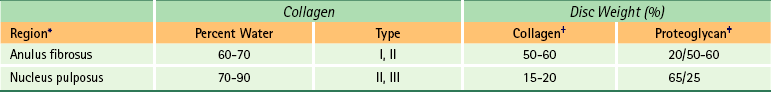
∗Values are for the lumbar spine (Bogduk, 1997).
†Percentage of dry weight of disc consisting of collagen.
‡Percentage of dry weight of disc consisting of proteoglycan/percentage of proteoglycan found in aggregated form.
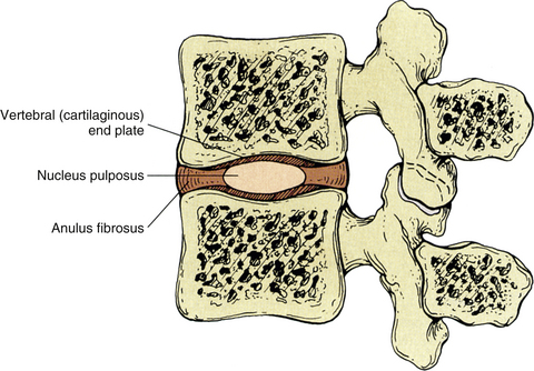
FIG. 2-12 Midsagittal section of two adjacent lumbar vertebrae and the intervertebral disc separating the two vertebral bodies. Notice the components of the intervertebral disc: anulus fibrosus, nucleus pulposus, and vertebral (cartilaginous) end plate.
Although each region of the disc has a distinct composition, the transition between the anulus fibrosus and the nucleus pulposus is rather indistinct. The main difference between the two regions is their fibrous structure (Humzah & Soames, 1988). Type I collagen (typical in tendons) predominates in the anulus fibrosus, and type II collagen (typical for articular cartilage) predominates in the nucleus pulposus. The histologic and biochemical composition of the IVD is currently an active field of research and has a great deal of potential clinical relevance. As mentioned previously, Chapter 14 discusses the histologic characteristics of the IVD in more detail, and Chapter 11 discusses the clinical relevance of pathology of the IVD in low back pain. The gross morphologic characteristics of the three regions of the disc are discussed in the following sections.
Anulus Fibrosus
The anuli fibrosi (singular, anulus fibrosus) in the lumbar region, and most likely the thoracic region, consist of several fibrocartilaginous lamellae, or rings, that are convex externally (Fig. 2-13; see also Fig. 2-12). The lamellae are formed by closely arranged collagen fibers and a smaller percentage (10% of the dry weight) of elastic fibers (Bogduk, 2005a). The majority of fibers of each lamella run parallel with one another at approximately a 65-degree angle from the vertical plane. The fibers of adjacent lamellae overlie each other, forming a 130-degree angle between the fibers of adjacent lamellae. The fiber direction in the lamellae can vary considerably both among individuals and from one vertebra to the next (Humzah & Soames, 1988). The most superficial lamellae of the anulus fibrosus (AF) attach via Sharpey’s fibers (see Chapter 14 and Fig. 14-9) directly to the vertebral bodies in the region of the ring apophysis. They anchor themselves to the zone of compact bone that forms the outside of the vertebral rim, as well as the adjacent vertebral body and periosteum that covers it (Humzah & Soames, 1988). The inner lamellae of the AF attach to the cartilaginous vertebral end plate.
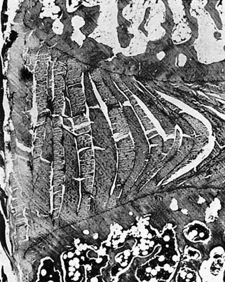
FIG. 2-13 Low-power photomicrograph demonstrating the lamellar arrangement of the anulus fibrosus. (Courtesy Vernon R & Jayson M. [1992]. The lumbar spine and back pain [4th ed.]. New York: Churchill Livingstone.)
The cervical intervertebral discs have been found to differ significantly from the lumbar discs (Mercer & Bogduk, 1999). Rather than consisting of many lamellae, the AF in the cervical region is composed of a single, crescent-shaped piece of fibrocartilage that is thick anteriorly and becomes narrow laterally. Posteriorly the AF is composed of only a single thin lamella. Like the lumbar region, the nucleus pulposus fills the central region of the cervical intervertebral discs and the cartilaginous end plates (CEPs) are found above and below the nucleus pulposus and AF. However, the cervical IVDs of children are similar to those of the lumbar region of children and adults. The changes that distinguish the cervical IVDs from those of the lumbar region begin as clefts in the AF (uncovertebral clefts), and develop adjacent to the uncinate processes during adolescence. During the third and fourth decades of life the shearing forces of cervical movements cause these clefts to extend medially, eroding the posterior AF until it is severely narrowed. This creates the crescent-shaped AF of the adult cervical spine (Taylor, 1999).
Further investigation is needed to precisely determine the composition of the thoracic IVDs. However, the IVDs of the thoracic region are currently thought to be similar in composition to those of the lumbar region.
Under normal conditions, the entire IVD is seldom subjected to pure tensile loads (traction forces). Even with clinical traction to the spine, the disc is under some compressive load because of muscle action. The AF is subject to tension stresses in all directions under various movements of the spine and under various conditions. The following list states the movement or condition followed by the region of the anulus that experiences tensile forces during that movement or condition:
• Side bending = convex side of bend
• Axial rotation = tensile stress develops approximately 45 degrees to the plane of the disc
• Compressive loading = entire anulus receives tensile loads during compression because of the outward pressure of the nucleus pulposus against the AF during compression
The AF has a significant load-bearing function, which it can perform even when the nucleus has been experimentally removed (Humzah & Soames, 1988). The various movements of the spine also create compressive forces on the IVD. As a result, during flexion the anterior aspect of the AF bulges outward. The opposite occurs during extension (posterior AF bulges outward), and the AF bulges toward the concavity of the curve during left and right lateral flexion. The anterior aspect of the disc is stronger than the rest, whereas the posterolateral aspect of each disc is the weakest region. Therefore the posterolateral aspect of the IVD is the region most prone to protrusion and extrusion.
The most superficial lamellae of the anulus of the lumbar region and the peripheral aspect of the cervical AF are innervated by general somatic afferent nerves and general visceral afferent nerves (which track with sympathetic efferent fibers). Specifically the recurrent meningeal nerve innervates the posterior aspect of the anulus, and separate nerves arising from the ventral ramus and the sympathetic chain innervate the lateral and anterior aspects of the anulus.
Clinical Implications Related to the Intervertebral Disc
The arrangement of collagen fibers is designed to protect the IVD during bending and torsion, the same motions that place the most stress on the AF (Hickey & Hukins, 1980). Disc saturation (intradiscal pressure) and compression also are related to failure of the AF. Therefore compressive (axial) loading, bending and twisting, and normal disc saturation together can cause failure of the AF, and lack of any one of these factors makes failure of the AF more difficult (Lu, Hutton, & Gharpuray, 1996). The posterior and lateral AF is the most vulnerable to failure (Edwards et al., 2001).
Weinstein and colleagues (1988) investigated the pain associated with discography. Discography is the injection of radiopaque dye into a disc and the subsequent visualization of the disc on x-ray film. They found neuropeptides, which are frequently identified as neurotransmitters associated with inflammation (substance P, calcitonin gene–related peptide, and vasoactive intestinal peptide), in the remaining lamellae of the AF and the dorsal root ganglia of dogs that had undergone surgical removal of an IVD (discectomy). They stated that the dorsal root ganglion may be a mediator of the sensory environment of the motor unit and that discs with anular disruption may be sensitized to further irritation. Therefore fibers whose cell bodies reside in the dorsal root ganglion may release the neurotransmitters listed previously into the region of the AF, making the anulus more sensitive to injury. This may mean that a torn or otherwise diseased disc could be more sensitive to further irritation and therefore more capable of nociceptive (pain) stimulation than the discs of adjacent vertebrae. This may help to explain the heightened pain sensitivity of patients with disc disorders. Weinstein and colleagues (1988) used their findings to help explain why the chemical irritants found in the radiopaque dye (Renografin) injected into a disc during discography (Fig. 2-14) reproduce the patient’s symptoms. However, the procedure generally is not associated with pain when the dye is injected into a neighboring healthy disc of the same individual. A further discussion of neuropeptides and chemokines associated with diseased IVDs is found in Chapter 11.
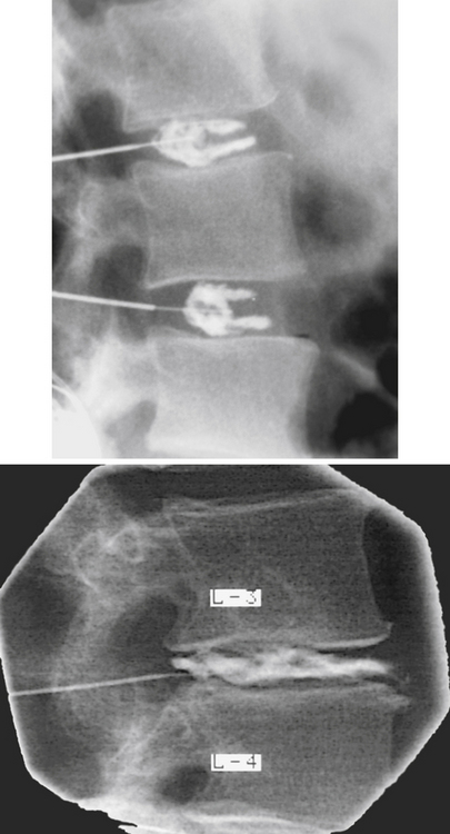
FIG. 2-14 Normal two-level discogram (top) and discogram demonstrating protrusion of nuclear material through the lamellae of the anulus fibrosus (bottom). (Images courtesy Dr. Dennis Skogsbergh.)
The lamellae of the AF are subject to tearing. These tears occur in two directions—circumferentially and radially. Many investigators believe that circumferential tears are the most common. This type of tear represents a separation of adjacent lamellae of the anulus, creating vertical clefts in the AF. The separation may cause the lamellae involved to tear away from their vertebral attachments as well. Using an aged rat model, Kuga and Kawabuchi (2001) found this type of disorganization (i.e., circumferential tears) among the protruded anular lamellae in disc protrusions (rather than extrusions). The changes also included widening of lamellae and flaccidity of lamellae. Such changes may help to explain the findings of Lipson (1988) and others (Willburger et al., 2004) that tissue removed from IVD “herniations” (extrusions) during surgery of patients older than 30 years was frequently found to be mostly AF when examined histologically (NP predominated in tissue removed from patients younger than 30 years). Such tissue removed during surgery may be protruded AF that has undergone the type of disorganization just mentioned, and could even be AF undergoing metaplastic change, rather than extruded nucleus pulposus, as is usually assumed to be the tissue removed from an IVD extrusion.
The second type of tear in the AF is radial in direction. These tears run from the deep lamellae of the anulus to the superficial layers, creating horizontal clefts in the AF. Most authors believe that these types of tears follow circumferential tears in chronology and that the circumferential tears make it easier for the development of radial tears (Ito et al., 1991). This is because the radial tears are able to connect the circumferential ones. When the connection occurs, the nucleus pulposus may be allowed to protrude, or even extrude, into the vertebral canal. Radial tears have been associated with IVD degeneration, as well as IVD protrusion and extrusion, and Krismer and colleagues (2000) found that IVD radial fissures were associated with a decreased IVD height as seen on x-rays. Herzog (1996) found radial tears in 21% to 35% of cadaveric lumbar IVDs older than age 40, but only rarely found such tears in cadavers younger than 40. Chapter 11 discusses the pathology of the IVD, including a full discussion of the terminology associated with IVD bulging, protrusion, and extrusion.
Nucleus Pulposus
The nucleus pulposus (NP) is a rounded region located within the center of the IVD (see Fig. 2-12). The NP is thickest from superior to inferior in the lumbar region, followed in thickness by the cervical region; it is the thinnest in the thoracic region. It is most centrally placed within the horizontal plane in the cervical region and is more posteriorly placed in the lumbar region (Humzah & Soames, 1988).
The NP develops from the embryologic notochord. It is gelatinous and relatively large just after birth, and several multinucleated notochordal cells can be found within its substance (Standring et al., 2008). The remnants of the notochord can be recognized in MRI scans as an irregular dark band, usually confined to the NP (Breger et al., 1988). The notochordal tissue has been found to be more apparent in fetal spines than in the spines of infants (Ho et al., 1988). The notochordal cells decrease in number over time and are almost completely replaced by fibrocartilage by approximately the eleventh year of life (Standring et al., 2008), and no notochordal cells normally remain after the mid-teens (Oda, Tamaka, & Tsukuki, 1988). As the notochordal cells are replaced, the outer aspect of the NP blends with the inner layer of the AF, making it more difficult to determine the border between the two regions. Notochordal cells may remain throughout the spine. These remnants are known as notochordal “rests” and may develop into neoplasms known as chordomas. Chordomas most commonly occur at the base of the skull and in the lumbosacral region (Humzah & Soames, 1988).
The adult disc is an avascular structure, except for the most peripheral region of the AF, and the NP is responsible for absorbing the majority of the fluid received by the disc. The process by which a disc absorbs fluid from the vertebral bodies above and below it has been termed imbibition. The size of the NP and its capacity to swell are greatest in the lumbar region, followed by the cervical region. The NP is 70% to 90% water and it reaches its peak hydration between the ages of 20 to 30 years, and the process of degeneration begins shortly thereafter (Coventry, 1969). The disc loses water when a load is applied but retains sodium and potassium. This increase in electrolyte concentration creates an osmotic gradient that results in rapid rehydration when the loading of the disc is stopped (Kraemer et al., 1985). This osmotic system of the IVD is sensitive to the forces applied to the disc, the pressure within the NP, and the composition and concentration of the proteoglycan molecules within the IVD (Kraemer, 1995). Frequent changes of posture are beneficial to this osmotic system, and the disc apparently benefits from both activity during the day (Holm & Nachemson, 1983; Kraemer, 1995) and the rest it receives during the hours of sleep. Because of the loss of fluid in the IVD during compression, the total body height is approximately 10 mm less at the end of an average day. This height is completely regained during 8 hours of sleep (Boos et al., 1996; McGill & Axler, 1996). Prolonged bed rest (up to 32 hours) does not significantly increase total body height, but the weightless environment of space can increase total body height by 40 to 60 mm (McGill & Axler, 1996). The diurnal variation in IVD height has been verified with both MRI (Botsford, Esses, & Olgilvie-Harris, 1994) and ultrasound (Boos et al., 1996; Ledsome et al., 1996). However, too much rest may not be beneficial. A decrease in the amount of fluid (hydration) of the IVDs has been noted on MRIs after 5 weeks of bed rest (LeBlanc et al., 1988).
The NP is a viscoelastic structure that can act as a fluid or solid depending on the rate and magnitude of loading. In addition, the NP can change its shape and position during different motions of the spine and when different loads are placed on the spine (Iatridis et al., 1996). For example, the NP of the lumbar region moves posteriorly during flexion and anteriorly during extension (Fennell, Jones, & Hukins, 1996).
In addition, the pressure within the NP changes as body position changes. When a person is positioned supine (lying on the back), the pressure within a lower lumbar NP is 20% of the pressure during standing. Leaning forward while sitting or standing substantially increases intradiscal pressure (IDP) (Nachemson, 1966) and causes the NP to migrate posteriorly (Alexander et al., 2007), and lifting a 20-kg load results in a 4.5-fold increase in IDP. This IDP is reduced by 25% if the knees are bent during lifting. In addition, if the load is held close to the body the IDP is reduced twofold. The IDP is lower in relaxed sitting than in relaxed standing, and slightly slouching while sitting actually decreases IDP, whereas straight sitting and straight standing both increase IDP. As might be expected, muscle activity increases IDP. During 7 hours of sleep the IDP increases approximately 240% compared with when one initially goes to bed (Wilke et al., 1999). This may support the hypothesis that herniation of the NP is more likely during the beginning of the day than at the end of the day.
Hysteresis is a viscoelastic phenomenon that refers to deformation of a tissue because of short duration loading. Hysteresis helps to protect the spine and nervous system during rapid loadings. For example, the successive vertebrae, intervertebral discs, and other tissues from the feet to the brain absorb the shock of jumping by means of hysteresis. Hysteresis increases as loads increase, is greatest in young tissues, and decreases with age. This phenomenon is diminished in the lower thoracic and upper lumbar regions, compared with the lower lumbar region of the spine. Hysteresis also decreases when the same disc is loaded a second time, and continues to decrease with repetitive loading. Decreased hysteresis may be a factor in the increased incidence of extruded NP in those with driving occupations (i.e., repetitive loading from subtle and erratic bouncing).
As the NP ages, it becomes less gelatinous in consistency, its ability to absorb fluid diminishes, and the intradiscal pressure diminishes. The changes in composition and structure that are common to all sources of cartilage with aging occur earlier and to a greater extent in the IVD (Bayliss et al., 1988). In fact, the normal aging process of the IVD is difficult to differentiate from IVD degeneration (Boos et al., 2002), although there are differences between these two processes (Adams, 2005). Breakdown of the proteoglycan aggregates and monomers (see Fig. 14-6) is thought to contribute to this process of aging and degeneration. The breakdown of proteoglycans results in a decreased ability of the disc to absorb fluid, which leads to a decrease in the ability of the disc to resist loads placed on it. The degeneration associated with the decrease in ability to absorb fluid (water) has been identified through use of CT (Bahk & Lee, 1988) and MRI and has been correlated with histologic structure and fluid content. As the disc degenerates, it narrows in the superior to inferior dimensions and the adjacent vertebral bodies may become sclerotic (thickened and opaque on x-ray) (Moore et al., 1996a,b). Much of the disc thinning with age seen on x-ray may also be the result of the disc sinking into the adjacent vertebral bodies over the course of many years (Humzah & Soames, 1988).
Pathologic conditions of the IVD are frequently seen in clinical practice. As mentioned, the NP may cause bulging of the outer anular fibers or may protrude (herniate) through some or all of the lamellae of the AF. This was first described by Mixter and Barr (1934). Bulging or protrusion of the disc may be a primary source of pain, or pain may result because of pressure on the exiting nerve roots within the medial aspect of the intervertebral foramen. Such bulging is usually associated with heavy lifting or trauma, although such a history may be absent in as many as 28% of patients with confirmed disc protrusion (Martin, 1978). Vibration along with sudden loading has been shown to exacerbate disc herniations (Yates & McGill, 2011). Some investigators believe that proteoglycan and other molecules leaking from a tear in the anulus also may cause pain by creating a chemical irritation of the exiting nerve roots. The pain that results from pressure on or irritation of a nerve root radiates in a distribution along the nerves supplied by the compressed nerve root (see Chapter 11). Such pain is termed radicular pain because of its origin from the dorsal root (radix) or dorsal root ganglion. Treatment for protrusion of the NP ranges from excision of the disc (discectomy) to employment of conservative methods (Sanders & Stein, 1988; Brønfort, 1997).
Vertebral (Cartilaginous) End Plates
The vertebral end plates, or cartilaginous end plates (CEPs), limit all but the most peripheral rim of the disc superiorly and inferiorly. They are attached both to the disc and to the adjacent vertebral body (see Fig. 2-12). Although a few authors consider the vertebral end plate to be a part of the vertebral body, most authorities consider it to be an integral portion of the disc (Coventry, 1969; Bogduk, 2005a). The CEPs are approximately 1 mm thick peripherally and 3 mm thick centrally. They are composed of both hyaline cartilage and fibrocartilage. The hyaline cartilage is located against the vertebral body, and the fibrocartilage is found adjacent to the remainder of the IVD. The end plates help to prevent the vertebral bodies from undergoing pressure atrophy and, at the same time, contain the AF and NP within their normal anatomic borders.
The CEPs are very important for proper nutrition of the disc (Humzah & Soames, 1988). They are extremely porous and allow fluid to enter and leave the AF and NP by osmotic action (Humzah & Soames, 1988). Very early in postnatal life, small vascular channels enter the vertebral side of the vertebral end plate and a few channels enter the outermost lamella of the AF. These channels disappear with age and are almost completely gone by the age of 12, leaving the IVD to obtain all of its nutrition by means of imbibition through the CEP (Boos et al., 2002). The end plate is more permeable in the region adjacent to the NP and is relatively impermeable in the region associated with the AF. This may result from morphologic differences in the capillary beds of the bony end plates. These beds are more complex in the region surrounding the NP (Oki et al., 1996).
The first structures to fail with compressive loading of the vertebral column are the CEPs and the adjacent subchondral bone of the vertebral bodies (bony end plates) (Hickey & Hukins, 1980). Such fractures allow the NP to rupture through the CEP, causing a lesion known as a Schmorl’s node. These nodes cause the vertebrae surrounding the lesion to move closer together. This movement is thought to increase pressure on the posterior and anterior joints between the vertebrae, increasing the degenerative process of the anterior interbody joint (the remainder of the IVD). In addition, the disc thinning or narrowing that results from these end plate herniations causes more force to be borne by the Z joints and may result in more rapid degeneration of these structures as well.
The CEPs begin to calcify and thin with advancing years. This leaves them more brittle. The central region of the end plate in some vertebrae of certain individuals may be completely lost in the later years of life.
Innervation of the Intervertebral Discs
The entire outer third of the AF has been found to receive both sensory and vasomotor innervation (Bogduk, Tynan, & Wilson, 1981). The sensory fibers probably are both nociceptive (pain sensitive) and proprioceptive in nature, and an extensive distribution of small nerve fibers (both A-delta and C) has been found throughout the peripheral aspect of the AF (Cavanaugh et al., 1995). The vasomotor fibers of the AF are associated with the small vessels located along its most superficial aspect. The posterior aspect of the disc receives its innervation from the recurrent meningeal nerve (sinuvertebral nerve). The posterolateral aspect of the anulus receives both direct branches from the anterior primary division and also branches from the gray communicating rami of the sympathetic chain. The lateral and anterior aspects of the disc receive their innervation primarily from branches of the gray communicating rami and also branches from the sympathetic chain. The central CEP adjacent to the NP also receives a sensory innervation similar to that of the outer AF.
The very strong contribution of afferents associated with the sympathetic nervous system to the innervation of the IVD has led some to observe that the innervation to the disc is different from the innervation to most musculoskeletal tissues, and that the innervation to the IVD is actually similar to that of visceral, specifically enteric, organs. These findings indicate that discogenic pain may be a type of visceral pain (Edgar, 2007).
Degenerated discs receive increased innervation by sensory fibers conducting nociception. Both the number of sensory nerve endings increases and the nerve endings extend deeper into the AF. The nerve endings are both nociceptive and mechanoreceptive and inflammation may sensitize (peripheral sensitization) the mechanoreceptive endings. The increased innervation by nociceptive and mechanoreceptive sensitive endings indicates that injured or degenerated discs are more sensitive to inflammation and pressure and that stimulation of these endings may be interpreted as pain (Coppes et al., 1997; Edgar, 2007). Schwann cells of the nerves innervating the outer layers of the AF appear to play a role in this ingrowth of sensory nerves (Johnson et al., 2001).
These findings just described indicate that the IVD itself is most likely able to generate pain. Therefore disorders affecting the IVDs alone (e.g., internal disc disruption, tears of the outer third of the AF, and possibly even marked disc degeneration) can be the sole cause of back pain. The disc can also generate pain by compressing (entrapping) an exiting dorsal root. As mentioned, leakage of nerve-irritating (histamine-like) molecules from disrupted IVDs also has been found to be a cause of irritation to the exiting dorsal root. These latter conditions cause a sharp, stabbing pain that radiates along the distribution of the nerves receiving fibers from the dorsal root. This type of pain is known as radicular pain because it results from irritation of a nerve root (radix). Chapter 11 describes the differentiation of radicular pain from somatic referred pain. The unique characteristics of the innervation to the IVDs of the specific spinal regions are discussed in Chapters 5 through 7.
Relationship of the Spinal Nerves to the Intervertebral Disc
The first seven spinal nerves exit through the intervertebral foramen (IVF) located superior to the vertebra of the same number (e.g., the C5 nerve exits the C4-5 IVF). This relationship changes at the eighth cervical nerve. Because there are eight cervical spinal nerves and only seven cervical vertebrae, the eighth cervical nerve exits the IVF between C7 and T1 (i.e., inferior to C7). All spinal nerves located below the C8 cervical nerve exit inferior to the vertebra of the same number (e.g., the T5 nerve exits below T5, through the T5-6 IVF). Figures 3-7 and 3-8 show this relationship.
The aforementioned information is of clinical importance. Because of the relationships just discussed, a disc protrusion occurring at the level of the C3-4 disc usually affects the exiting C4 nerve. However, a disc protrusion of the T3-4 IVD normally affects the T3 spinal nerve. The anatomic relationships of a disc protrusion in the lumbar spine are unique. As expected, the exiting spinal nerve passes through the IVF located below the vertebra of the same number (e.g., L3 nerve through the L3-4 IVF). However, the spinal cord usually ends between L1 and L2 (see Chapter 3, Table 3-1), and below this the lumbar and sacral roots descend inferiorly, forming the cauda equina. To exit an IVF, the sharply descending nerve roots must make a rather dramatic turn laterally, and as each nerve root exits, it “hugs” the pedicle of the most superior vertebra of the IVF (Fig. 2-15). Because they leave at such an angle, the nerve roots are kept out of the way of the IVD at the same level. Even though they are positioned away from the disc at their level of exit, they do pass across the IVD above their level of exit. This is approximately where they enter the dural root sleeve, and this is also where the nerve roots may be compressed by disc protrusions. The other nerve roots of the cauda equina are not as vulnerable at this location because only the nerve beginning to exit the vertebral canal has entered its dural root sleeve. Once in the sleeve, the exiting nerve roots are contained and more or less held in place as they descend to exit the IVF. This more firmly positions the exiting roots against the disc above the level of exit (see Fig. 2-15). The other nerve roots of the cauda equina, within the subarachnoid space of the lumbar cistern, “float” away from a protruding disc. The result is that a lumbar disc protrusion normally affects the nerve roots exiting the subjacent IVF (e.g., an L3 disc protrusion affects the L4 nerve roots).
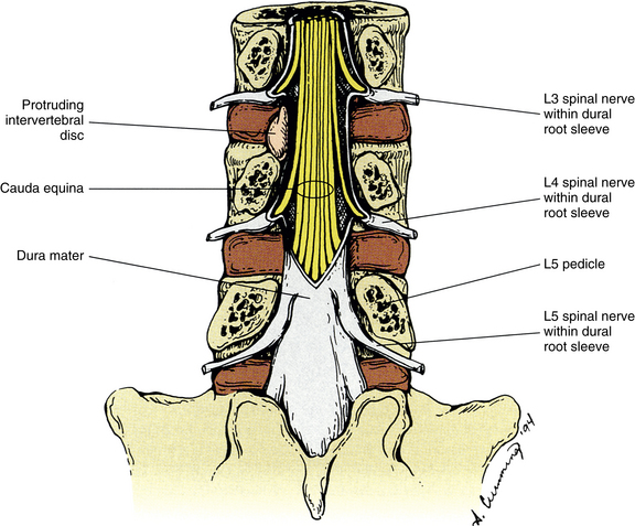
Syndesmoses of the Spine
In addition to the Z joints and the interbody symphysis, the spine also contains a number of joints classified as syndesmoses (see Appendix I). Recall that a syndesmosis is a joint consisting of two bones connected by a ligament. The spine is unique in that it has several examples of such joints. The spinal syndesmoses include the following:
• Axial-occipital syndesmosis (between odontoid and clivus; ligaments include cruciform, apical-odontoid, and alar)
• Ligamentum nuchae (syndesmosis between occiput and C1-7)
• Laminar syndesmosis (ligamentum flavum)
• Intertransverse syndesmosis (intertransverse ligament)
• Supraspinous syndesmosis (supraspinous ligament)
• Interspinous syndesmosis (interspinous ligament)
• See Appendix I for additional syndemoses
The syndemoses listed above are innervated by the posterior primary division (dorsal ramus) exiting between the two vertebrae connected by the ligaments. The exception to this is the axial-occipital syndesmosis, which is innervated by the anterior primary division (ventral ramus) of the first cervical nerve. Afferent nerves coursing with sympathetic nerves also innervate these spinal syndesmoses. The ligaments forming these joints are discussed in Chapters 5 through 7.
Vertebral Canal
The chapter has thus far been devoted to a discussion of the relatively solid elements of the spine (e.g., bones, ligaments, and joints). The remainder of the chapter is devoted to the “holes” (Latin, foramen, singular; foramina, plural) of the spine, the structures that run through them, and the clinical significance of these openings.
A vertebral foramen (see Fig. 2-3, B) is the opening within a vertebra through which the spinal cord or cauda equina passes. The vertebral foramen can be best defined by listing its boundaries. The boundaries of a typical vertebral foramen include the following:
The boundaries of a vertebral foramen are shown in Figure 2-3, B. Two congenital anomalies can affect the vertebral foramen. The first is failure of the posterior elements of a vertebra to fuse during development. This is known as spina bifida (see Chapter 12). Another congenital anomaly of the vertebral foramen is the development of a fibrous or bony bridge between the vertebral body and the spinous process. Such a bridge may divide the spinal cord midsagittally at that level. This condition, known as diastematomyelia, may remain unnoticed throughout life or may become symptomatic later in life or after trauma.
The collection of all of the vertebral foramina is known as the vertebral (spinal) canal. Therefore the IVDs and the posteriorly located ligamenta flava (ligamentum flavum, singular) also participate in the formation of the vertebral canal. The ligamenta flava are discussed in detail in Chapter 5.
The vertebral canal is fairly large in the upper cervical region but narrows from C3 to C6. In fact, the spinal cord fills 75% of the vertebral canal at the C6 level. Therefore the lower cervical cord is particularly vulnerable to a wide variety of pathologic entities that can compromise the cord within the vertebral canal. These include IVD protrusion, hypertrophy of the ligamentum flavum, space-occupying lesions, and arteriovenous malformations.
The vertebral canal follows the normal contour of the curves of the spine. The vertebral foramina are relatively large and triangular in the cervical (Fig. 2-16, also see Fig. 5-1) and lumbar regions (Fig. 2-16, also see Fig. 7-2), where there is a great deal of spinal movement. The vertebral canal in the thoracic region is smaller and almost circular in configuration (Fig. 2-16, also see Fig. 6-1). This may result from the fact that the thoracic spine undergoes less movement than the other regions of the spine. Also, the vertebral canal in the thoracic region is not necessarily as large as that in the cervical region because the thoracic spinal cord is narrower than the cervical cord, which contains the cervical enlargement.
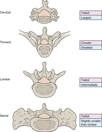
FIG. 2-16 Shapes (peach in figure, pink in boxes) and relative sizes (blue) of the cervical, thoracic, and lumbar vertebral foramina and sacral canal.
The size of the vertebral canal (see Chapters 5 and 7 for specific values) has been assessed by several investigators, most of whom were interested in the condition of spinal (vertebral) canal stenosis. This condition is defined as a narrowing of either the anteroposterior or the transverse diameter of the vertebral canal. Some investigators have shown a change in vertebral dimensions and canal size with normal aging (Leiviska et al., 1985). However, spinal canal stenosis seems to have a strong developmental component and may result, in part, from prenatal and perinatal growth disruption (Clarke et al., 1985). Vertebral canal growth is approximately 90% complete by late infancy. Because canal diameters do not undergo “catch-up growth” (Clarke et al., 1985), factors affecting canal size must occur before infancy. A significant relationship has been found between a decrease in anteroposterior vertebral foramen size and spinal cord constriction. As little as 2 mm in anteroposterior diameter separates persons with or without low back pain, and Clarke and colleagues (1985) suggest that as many as 53% of low back pain patients may have anteroposterior spinal stenosis. Clarke and colleagues (1985) believe that spinal stenosis and sciatica may have a developmental basis and that perhaps there is a higher association between canal size and low back pain than was realized previously. They believe that attention to prenatal and neonatal nutrition may play an important role in preventing back pain from this origin. In addition, they state that maternal smoking and other environmental factors have been shown to significantly reduce head circumference. They hypothesize that the same phenomena may occur with the vertebral canal (Clarke et al., 1985). If this is shown to be the case, reduction in maternal smoking may prevent future back pain in the offspring. Although a link between back pain and smoking has been made, the association is complex and more work is needed to validate the relationship (Leboeuf-Yde & Yashin, 1995). However, there is evidence from animal studies that the presence of systemic nicotine decreases the bony union of spine surgery fusion sites (intertransverse fusion), suggesting that nicotine may decrease the “biomechanical properties” of new bone formation (Silcox et al., 1995), and many prominent surgeons strongly suggest that a person stop smoking before undergoing a surgical procedure on the spine (Herkowitz et al., 1992).
Spinal canal stenosis also can be caused by the development of bone spurs (osteophytes) along the posterior aspect of the vertebral body, hypertrophy of the uncinate processes of the cervical vertebrae, hypertrophy of the articular processes constituting the zygapophysial joints, protrusion of the intervertebral disc, ossification of the posterior longitudinal ligament, and hypertrophy or buckling of the ligamentum flavum (Bailey & Casamajor, 1911; Giles, 2000). Further elaboration of the causes and consequences of spinal (vertebral canal) stenosis and foraminal (IVF) stenosis are discussed in more detail in the chapters on the cervical and lumbar regions (Chapters 5 and 7, respectively).
External Vertebral Venous Plexus
Before investigating the contents of the vertebral canal, it is necessary to discuss a plexus of veins that surrounds the outside of the vertebrae and the vertebral canal. This network of veins surrounding the external aspect of the vertebral column is known as the external vertebral venous plexus. The external vertebral venous plexus is associated with both the posterior and the anterior elements of the vertebral column and can be divided into an anterior external vertebral venous plexus surrounding the vertebral bodies and a posterior external vertebral venous plexus associated with the posterior arches of adjacent vertebrae. These plexuses communicate with segmental veins throughout the spine (e.g., deep cervical veins, intercostal veins, lumbar veins, and ascending lumbar veins) and also with the internal vertebral venous plexus, which lies within the vertebral canal. The external and internal vertebral plexuses communicate through the IVFs and also directly through the vertebral bodies (anterior plexus) and through the ligamenta flava (posterior plexus). The posterior external vertebral plexus has valves that direct flow into the posterior internal vertebral venous plexus (Stringer et al., 2012). Intervertebral veins, located at the superior and inferior aspects of the IVFs, connect the internal and external venous plexuses (Parke, 2005). The superior intervertebral veins surround the dorsal root ganglion, exiting nerve roots (Parke, 2005), and form a vascular cuff around the (more distal) spinal nerve (Humzah & Soames, 1988).
Epidural Space
The region immediately beneath the bony and ligamentous elements forming the vertebral canal is known as the epidural space (see dura mater in Fig. 2-15). Generally throughout the length of the vertebral canal, the epidural space is approximately 4 to 6 mm deep to the osseous and ligamentous anterior and posterior canal borders (Chen et al., 1989; Hackney, 1992). The epidural space is sometimes entered at the L3-4 interspinous space for the purpose of administering anesthetics. The depth to the epidural space at this level is 4.77 ± 0.55 cm in males and 4.25 ± 0.55 cm in females. The range of depth is 3.0 to 7.0 cm (1.2 to 2.8 inches), and there is a positive correlation between both body weight and body height with the depth to the epidural space (Chen et al., 1989).
The epidural space contains a venous plexus embedded in a thin layer of adipose tissue. The adipose tissue is known as the epidural adipose tissue, or epidural fat, and the venous plexus is known as the internal vertebral venous plexus.
Internal Vertebral Venous Plexus
The internal vertebral venous plexus is located beneath the bony elements of the vertebral foramina (e.g., laminae, spinous processes, pedicles, and vertebral body). As mentioned, it is embedded in a layer of loose areolar tissue known as the epidural (extradural) adipose tissue, although less adipose tissue surrounds the veins located in the anterior aspect of the epidural space. The internal vertebral venous plexus provides an alternate route of venous return when the jugular veins of the neck are compressed, when the flow through the inferior vena cava is obstructed, and when intrathoracic or intraabdominal pressures are increased. They also provide a protective cushion for the important contents of the vertebral canal (Stringer et al., 2012). The internal vertebral venous plexus is a clinically important plexus, and perhaps for this reason it has been given many names. It is known as the internal vertebral venous plexus, the epidural venous plexus, the extradural venous plexus, and also as Batson’s channels.
The internal vertebral venous plexus consists of approximately four interconnected longitudinal channels. Two course along the posterior aspect of the vertebral canal, and two channels of larger diameter course along the anterior aspect of the canal (Stringer et al., 2012). The posterior channels are rudimentary in the cervical region, but well developed in the thoracic and lumbar regions (Chaynes et al., 1998). The posterior channels are located along the posterolateral aspect of the vertebral canal in the thoracic region and are more laterally placed in the cervical (rudimentary channels) and lumbar regions (Stringer et al., 2012).
The anterior channels are located on either side of the posterior longitudinal ligament and drain the vertebral bodies via large basivertebral veins. The basivertebral veins pierce the center of each vertebral body and communicate posteriorly with the internal plexus and anteriorly with the external vertebral venous plexus. Posteriorly the basivertebral veins connect with horizontally oriented transverse veins that course anterior to the posterior longitudinal ligament. These transverse veins connect the left and right longitudinal channels of the anterior internal vertebral venous plexus (Stringer et al, 2012).
The veins of the internal vertebral venous plexus contain no valves; therefore the direction of drainage is posture and respiration dependent. Inferiorly this plexus is continuous with the prostatic venous plexus of the male, and superiorly (in both sexes) it is continuous with many veins and also to dura mater venous sinuses of the posterior cranial fossa. These superior connections include the following: vertebral veins, occipital veins, occipital sinus, sigmoid sinus, and inferior petrosal sinus (Stringer et al., 2012). Therefore prostatic carcinoma may metastasize via the intervertebral venous plexus to all regions of the spine and to the meninges and brain. Because of venous communications in the thoracic region, lung and breast cancers can metastasize to these veins as well. However, the veins of the internal vertebral venous plexus eventually (by means of intervertebral and ascending lumbar veins) drain into large veins. These large veins include the vertebral, for the cervical region; and the azygos, hemiazygos, and right highest intercostal veins, for blood draining the thoracic and lumbar regions. These large veins each have one or two valves at their entrance to the brachiocephalic veins (for the vertebral veins) or at their entrance to the azygos vein (for the right highest intercostal and hemiazygos veins). The azygos vein then drains directly into the superior vena cava, and there is also a valve at this entrance. These valves act as a protective mechanism, preventing reflux of blood (and the accompanying increase in pressure) into the internal vertebral venous plexus and the important neural tissues they serve (Scapinelli, 2000). However, diminished right-sided heart function can lead to congestion and engorgement of the intervertebral veins, coursing through the IVFs, and veins of the internal vertebral venous plexus. Such venous congestion, usually when coupled with narrowing (stenosis) of the vertebral canal, can exacerbate inflammation of dorsal roots and/or dorsal root ganglia and lead to pain typically associated with prolonged recumbency (e.g., during sleep) (Parke, 2005).
The walls of the longitudinal veins of the internal vertebral venous plexus are very distinct. These walls have many trabeculae composed of collagen and smooth muscle that create a series of interconnected, parallel channels for blood flow within the individual longitudinal veins. The trabeculae are supplied by small nerve endings and arteries. The trabeculae are thought to prevent overdistension or collapse of the vessels and may help to regulate the direction and velocity of blood flow within the vessels (Stringer et al., 2012). However, segments of the longitudinal veins, and all of the horizontal connecting and intervertebral veins (the latter coursing through the intervertebral foramina), are devoid of these reinforcements. These trabeculae-free regions appear to be more vulnerable to distension and collapse. Isolated regions of the veins have been found to become dilated (varices of epidural veins; that is, epidural venous engorgement) (Parke, 2005). These regions are likely related to the trabeculae-free areas of the veins. The varices that can develop in these regions, and in the intervertebral veins, may compress the exiting spinal nerves and cause radiculopathy (i.e., pain coursing along the distribution of the dorsal root that contributes to the formation of the spinal nerve). Radiculopathy from this cause can mimic that more commonly caused by an IVD protrusion (Wong et al., 2003). In addition, the veins can collapse from the pressure of an IVD protrusion. This fact has been used in a procedure known as epidural venography (Fig. 2-17) to aid in the diagnosis of IVD disease. In epidural venography, radiopaque dye is injected into the epidural veins and x-ray films are taken. This allows the veins filled with dye to be visualized (Jayson, 1980). Pressure from a disc protrusion prevents the veins from filling and is seen as an area devoid of dye on the x-ray film.
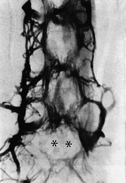
FIG. 2-17 Epidural venogram. Radiopaque dye was injected into the epidural venous plexus, x-ray films were taken, and extraneous tissue was removed using digital subtraction techniques. (Asterisks) An intervertebral disc protrusion; notice that the dye has not filled the veins in this region. (Courtesy Parke W. From Jayson M. [1980]. The lumbar spine and back pain [2nd ed.]. Baltimore: Urban & Schwarzenberg and Pitman Medical Publishing.)
Spinal epidural hematoma is a condition in which bleeding occurs into the space surrounding the dura mater. It is usually the result of a ruptured epidural vein and is rather rare, with only 250 cases reported in the literature. Of these cases, approximately 50% are spontaneous and of unknown cause. The causes of the remainder of the cases include trauma, anticoagulant therapy, and arteriovenous malformation. Spinal epidural hematoma may simulate IVD protrusion but can usually be identified through MRI (Mirkovic & Melany, 1992). The treatment protocol usually involves the release of pressure (decompression) by the removal of a lamina (laminectomy), although several cases with spontaneous recovery have been reported (Sei et al., 1991).
Meningeal and Neural Elements within the Vertebral Canal
The meningeal and neural elements of the vertebral canal are thoroughly discussed in Chapter 3. This section focuses on the neural elements that enter and leave the vertebral canal.
Beneath the epidural venous plexus and epidural adipose tissue lie the meninges, which surround the spinal cord (Fig. 2-18). These layers of tissue are known as the dura mater, arachnoid mater, and pia mater. The space between the meninges and the borders of the vertebral canal is known as the epidural space. Recall that this space is approximately 4 to 6 mm anteriorly and posteriorly throughout the length of the vertebral canal (Chen et al., 1989; Hackney, 1992).
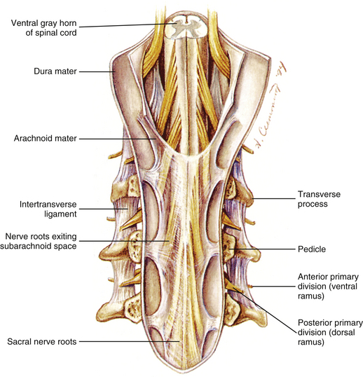
FIG. 2-18 Vertebral canal with the posterior vertebral arches removed. Notice the dura mater, arachnoid, and neural elements within the canal.
The spinal cord lies deep to the dura, arachnoid, and pia mater (see Fig. 2-18). Beneath the transparent pia mater, dorsal and ventral rootlets can be seen attaching to the spinal cord. These rootlets divide the spinal cord into spinal cord segments (see Chapter 3). A spinal cord segment is the region of the spinal cord delineated by those exiting dorsal and ventral rootlets that eventually unite to form a single spinal nerve. Spinal cord segments can be identified easily on a gross specimen of the spinal cord (see Figs. 3-6 and 3-11, C). The rootlets combine to form dorsal roots (from dorsal rootlets) and ventral roots (from ventral rootlets). The dorsal and ventral roots then unite to form a spinal nerve. The rootlets are “exceedingly delicate and vulnerable and when implicated in fibrous adhesions from whatever cause, undergo irreversible changes” (Domisse & Louw, 1990).
Formation of the Spinal Nerve and Anterior and Posterior Primary Divisions
The dorsal and ventral roots unite within the IVF to form the spinal nerve (Fig. 2-19; see also Chapter 3). As the spinal nerve exits the IVF, it divides into two parts: a posterior primary division (dorsal ramus) and an anterior primary division (ventral ramus) (see Figs. 2-18 and 2-19). The posterior primary division further divides into a medial branch, which supplies the Z joints and transversospinalis group of deep back muscles; and a lateral branch, which supplies the sacrospinalis group of deep back muscles (see Chapter 4). The anterior primary division may unite with other anterior primary divisions to form one of the plexuses of the body. Anterior primary divisions also innervate the body wall; the intercostal nerves serve as a prime example of this function. The plexuses of the anterior primary divisions and the specific innervation of spinal structures by the posterior primary divisions are discussed in the chapters covering the specific regions of the spine (see Chapters 5 through 8). The plexuses are discussed in the chapter dealing with the spinal region from which they arise.
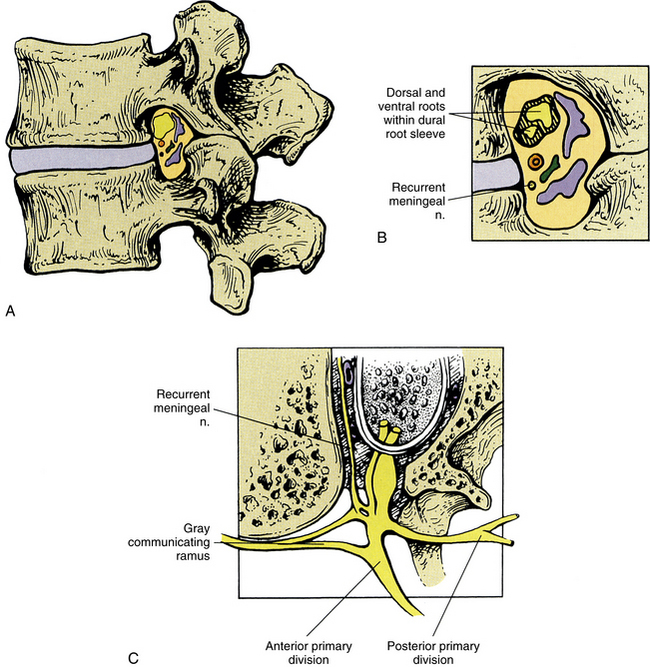
FIG. 2-19 A-C, Lumbar intervertebral foramen. In addition to the structures labeled, notice the intervertebral veins (blue), the spinal branch (ramus) of a lumbar segmental artery (red), and a lymphatic channel (green). C, Horizontal section through the intervertebral foramen. Notice that the recurrent meningeal nerve originates from the most proximal portion of the anterior primary division and receives a branch from the gray communicating ramus. It then passes medially to enter the intervertebral foramen.
Arterial Supply to the Spine
The external aspect of the vertebral column receives its arterial supply from branches of deep arteries “in the neighborhood” (see Fig. 2-4). The cervical region is supplied by the left and right deep cervical arteries (from the costocervical trunks) and also the right and left ascending cervical arteries (from the right and left inferior thyroid arteries). The thoracic region of the spine is supplied by posterior intercostal arteries, and the lumbar region is supplied by lumbar segmental arteries.
The internal aspect of the vertebral canal receives its arterial supply from segmental arteries that send spinal branches into the IVFs (see Fig. 2-4). The segmental arteries are branches of the vertebral artery in the cervical region, the posterior intercostal arteries in the thoracic region, and the lumbar segmental arteries in the lumbar region.
On entering the IVF, each spinal branch (ramus) of a segmental artery further divides into three branches. One branch courses posteriorly to supply the laminae and ligamenta flava, and a large branch usually courses to the spinous process, where it enters the base of this process and continues posteriorly to reach its posterior tip. Other arterial twigs from the posterior branch supply the extradural adipose tissue and other small branches course to the posterior spinal dura mater. A large branch enters the lamina close to its junction with the pedicle. On entering the lamina, an ascending branch and a descending (the longer of the two) branch course through the superior and inferior articular processes, respectively, to reach the subchondral bone of the articular facets (Crock & Yoshizawa, 1976).
Another branch of the spinal ramus of a segmental artery courses anteriorly. This anterior branch bifurcates into large offshoots to the center of the posterolateral aspect of the vertebral body and then divides into an ascending and a descending branch. The ascending branch crosses the IVD above and joins the descending branch of the level above. The descending branch courses near the pedicle, sending branches to it. The ascending and descending branches both supply the posterior aspect of the vertebral bodies and also send twigs to the posterior longitudinal ligament (Crock & Yoshizawa, 1976).
The third branch of each spinal ramus of a segmental artery, known as the neural branch, courses to the spinal nerve. The neural branch then divides into an anterior and a posterior radicular artery to supply the ventral and dorsal nerve roots and rootlets, respectively. The posterior radicular artery also supplies a branch to the distal pole and another to the proximal pole of the dorsal root ganglion (polar dorsal root ganglion arteries) (Parke, 2005). The spinal cord, the vasculature of the cord (including radiculomedullary arteries), and its meningeal coverings are discussed in detail in Chapter 3, and the unique characteristics of the blood supply to each region of the spine are discussed in further detail in the chapters on specific regions of the spine (Chapters 5 through 8).
Intervertebral Foramen
The second major opening, or foramen, of the spine is the intervertebral foramen. The IVF is an area of great biomechanical, functional, and clinical significance (Standring et al., 2008). Much of its importance stems from the fact that the IVF provides an osteoligamentous boundary between the central nervous system and peripheral nervous system. This foramen is unlike any other in the body in that the spinal nerve and vessels running through it are passing through an opening formed by two movable bones (vertebrae) and two joints (the anterior interbody joint and the Z joint) (Amonoo-Kuofi et al., 1988a). Because of this the IVFs change size during movement. The superior-inferior dimension of the IVFs can change more than 44% during flexion and extension, becoming larger in spinal flexion and smaller in extension (Amonoo-Kuofi et al., 1988a; Awalt et al., 1989; Mayoux-Benhamou et al., 1989; Schmid et al., 1999). Compression of the exiting spinal nerves or other foraminal contents has been reported to be an important cause of back pain and pain radiating into the extremities (Amonoo-Kuofi et al., 1988a). Hasue and colleagues (1983) found evidence that osseous tissue can constrict neurovascular tissue in the nerve root tunnel (IVF). Such osseous tissue can include the uncinate processes in the cervical region; the ribs and their vertebral attachments forming the costocorporeal (costovertebral) joints in the thoracic region; and the intervertebral discs (Hadley, 1948; 1949), vertebral bodies, and articular processes of the Z joints (Bailey & Casamajor, 1911) in the lumbar region. Therefore knowledge of the specific anatomy of this clinically important area is important in the differential diagnosis of back and extremity pain and can help with the proper management of individuals with compromise of this region.
A pair (left and right) of IVFs are located between all of the adjacent vertebrae from C2 to the sacrum. The sacrum also has a series of paired dorsal and ventral foramina (see Chapter 8). There are no IVFs between C1 and C2. Where present, the IVFs lie posterior to the vertebral bodies and between the inferior and superior vertebral notches of adjacent vertebrae. Therefore the pedicles of adjacent vertebrae form the roof and floor of this region. The width of the pedicles in the horizontal plane gives depth to these openings, actually making them neural canals (Czervionke et al., 1988) rather than foramina, but the name intervertebral foramina remains.
Six structures form the boundaries of the IVF (see Fig. 2-19, A and B). Beginning from the most superior border (roof) and continuing anteriorly in a circular fashion, the boundaries include the following:
1. The pedicle of the vertebra above (more specifically, its periosteum)
2. The vertebral body of the vertebra above (again, its periosteum)
3. The IVD (posterolateral aspect of the AF)
4. The vertebral body of the vertebra below, and in the cervical region, the uncinate process (periosteum)
5. The pedicle (periosteum) of the vertebra below forms the floor of the IVF. A small part of the sacral base (between the superior articular process and the body of the S1 segment) forms the floor of the L5-S1 IVF.
6. The Z joint forms the “posterior wall.” Recall that the Z joint is composed of the following: (a) the inferior articular process (and facet) of the vertebra above, (b) the superior articular process (and facet) of the vertebra below, and (c) the anterior articular capsule, which is composed of the ligamentum flavum (Xu et al., 1991; Giles, 1992) (the posterior articular capsule is not directly related to the IVF).
The IVFs are smallest in the cervical region, and generally there is a gradual increase in IVF dimensions to the L4 vertebra. The left and right IVFs between L5 and S1 are unique in size and shape (see the following discussion). The different characteristics of the cervical, thoracic, and lumbar IVFs are covered in the chapters on regional anatomy of the spine (Chapters 5 through 7).
As mentioned, the IVFs are actually canals. These canals vary in width from approximately 5 mm (Hewitt, 1970) in the cervical region to 18 mm (Pfaundler, 1989) at the L5-S1 level.
Many structures traverse the IVF (see Fig. 2-19). They include the following:
• The spinal nerve (union of dorsal and ventral roots).
• The spinal branch (ramus) of a segmental artery. Recall that this artery divides into three branches: one to the posterior aspect of the vertebral body, one to the posterior arch, and one to the spinal nerve (neural branch).
• Communicating (intervertebral) veins between the internal and external vertebral venous plexuses.
Adipose tissue surrounds all of the listed structures.
The dorsal and ventral roots unite to form the spinal nerve in the region of the IVF, and the spinal nerve is surrounded by the dural root sleeve. The dural root sleeve is attached to the borders of the IVF by a series of fibrous bands. The dural root sleeve becomes continuous with the epineurium of the spinal nerve at the lateral border of the IVF (see Fig. 2-15). The arachnoid blends with the perineurium proximal to the dorsal root ganglion and at an equivalent region of the ventral root (Hewitt, 1970). Occasionally the arachnoid extends more distally, and in such cases the subarachnoid space extends to the lateral third of the IVF.
Each recurrent meningeal nerve (sinuvertebral nerve of von Luschka) originates from the most proximal portion of the ventral ramus. It receives a branch from the nearest gray communicating ramus of the sympathetic chain before traversing the IVF. This nerve provides sensory innervation (including nociception) to the posterior aspect of the AF, posterior longitudinal ligament, periosteum of the posterior aspect of the vertebral bodies, anterior epidural veins, and anterior aspect of the spinal dura mater. Usually several recurrent meningeal nerves enter the same IVF. These nerves are discussed in more detail in Chapters 5 and 11.
Since the beginning of the twentieth century, the IVF has been a region that has received much attention for a variety of reasons from those engaged in the treatment of the spine. The effect of spinal manipulation on the nerve roots and spinal nerves is an area of acute interest and much debate. In addition, lumbar IVFs have received much scrutiny because of their extreme clinical importance in lumbar IVD protrusion and lumbar intervertebral foraminal (canal) stenosis. In the words of Lancourt and colleagues (1979), “The importance of the nerve root entrapment in the nerve root canals cannot be overemphasized.” The arteries, veins, lymphatics, and particularly the neural elements may be adversely affected by pathologic conditions of one or more of the following structures (Standring et al., 2008):
• NP (especially in earlier decades)
• Red bone marrow of the vertebral bodies
• Compact bone of the pedicles
CT and MRI allow for accurate evaluation of the IVF in the living. Previous studies have shown both methods to be reliable in measuring the IVF in the sagittal plane (Cramer et al., 1992).
Figure 2-20 shows three parameters measured from MRI scans of the lumbar IVFs of normal human subjects. Table 2-6 shows the average values obtained from the left lumbar IVFs of 95 subjects (46 females and 49 males), and Table 2-7 gives the same values for the right side. Figure 2-21 shows the values displayed graphically. (Note: Because the values for the left and right IVFs respectively shown in Tables 2-6 and 2-7 are statistically the same, one graph can display the values for both sides.) The greatest superior to inferior dimension of the lumbar IVFs is at L2. This IVF dimension then diminishes until L5, where it is the smallest. The anteroposterior dimensions are smaller than the vertical dimension and remain quite constant throughout the lumbar region, with the more superior of the two anteroposterior measurements shown in Figures 2-20 and 2-21 being larger. Therefore the IVFs from L1 to L4 are similar in shape. They are shaped similar to an inverted pear. The L5 IVF is distinct in shape. It is more oval than the others, with the superior to inferior dimension being greater than the anteroposterior dimension (Cramer et al., 2003).
Table 2-6
Dimensions of Left Lumbar (LL) Intervertebral Foramina∗
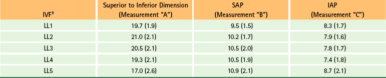
∗The average size of the left L1-5 IVFs for three measured parameters (Figs. 2-20 and 2-21). Values given in millimeters with standard deviations in parentheses. Values calculated from 95 human subjects: 46 females and 49 males.
†IAP, Inferior anterior-posterior measurement taken at the level of the inferior vertebral end plate (measurement “C” in Fig. 2-20); IVF, intervertebral foramen; SAP, superior anterior-posterior measurement taken at the level of the Z joint (measurement “B” in Fig. 2-20).
From Cramer G et al. (2003). Dimensions of the lumbar intervertebral foramina as determined from the sagittal plane magnetic resonance imaging scans of 95 normal subjects. J Manipulative Physiol Ther, 26, 160-170.
Table 2-7
Dimensions of Right Lumbar (RL) Intervertebral Foramina∗
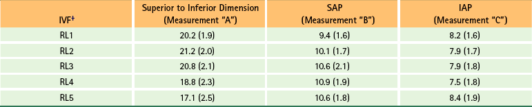
∗The average size of the left L1-5 IVFs for three measured parameters (Figs. 2-20 and 2-21). Values given in millimeters with standard deviations in parentheses. Values calculated from 95 human subjects: 46 females and 49 males.
†IAP, Inferior anterior-posterior measurement taken at the level of the inferior vertebral end plate (measurement “C” in Fig. 2-20); IVF, intervertebral foramen; SAP, superior anterior-posterior measurement taken at the level of the Z joint (measurement “B” in Fig. 2-20).
From Cramer G et al. (2l003). Dimensions of the lumbar intervertebral foramina as determined from the sagittal plane magnetic resonance imaging scans of 95 normal subjects. J Manipulative Physiol Ther, 26, 160-170.
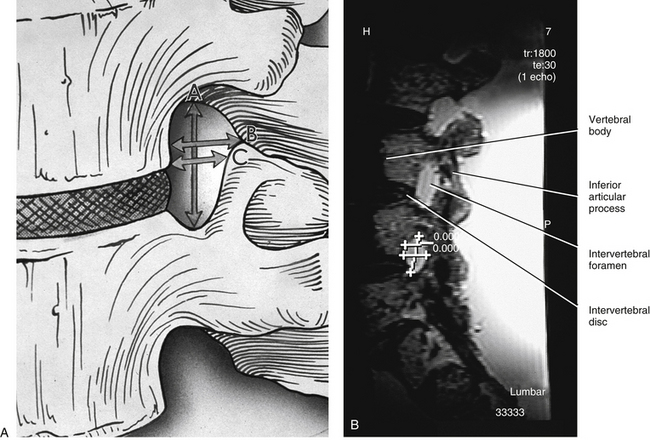
FIG. 2-20 (A) Illustration and (B) magnetic resonance imaging (MRI) scan demonstrating the 3 measurements made on the parasagittal MRI scans of 95 individuals. A, A = Superior-inferior (SI) measurement, B = upper (superior) anterior-posterior (SAP) measurement, C = lower (inferior) anterior-posterior (IAP) measurement. Summaries of the data from these measurements are shown in Tables 2-6 and 2-7 and Figure 2-21. B, The measurements read “0.00” because the scale was set to zero before this photograph was taken. This was done to avoid a distracting overlap of numbers on the image. (A, From Cramer G et al. [2003]. Dimensions of the lumbar intervertebral foramina as determined from the sagittal plane magnetic resonance imaging scans of 95 normal subjects. J Manipulative Physiol Ther, 26, 160-170.)
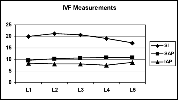
FIG. 2-21 Dimensions of the lumbar intervertebral foramina of 95 normal human subjects. Notice that the two anteroposterior measurements (superior and inferior anterior-posterior) remain almost the same throughout the lumbar region. The superior-inferior (SI) dimension is the greatest at L2 and then becomes progressively smaller. (From Cramer G et al. [2003]. Dimensions of the lumbar intervertebral foramina as determined from the sagittal plane magnetic resonance imaging scans of 95 normal subjects. J Manipulative Physiol Ther, 26, 160-170.)
The width of the IVF is normally the same in males and females. However, the height is approximately 0.5 mm less in females versus males. As one ages, the height of the IVF significantly decreases, whereas the upper anterior to posterior dimension increases. All of the IVF dimensions increase with an increase in overall height of an individual. However, as the weight of an individual increases, the width of the IVF decreases. Figure 2-22 demonstrates these relationships (Cramer et al., 2003).
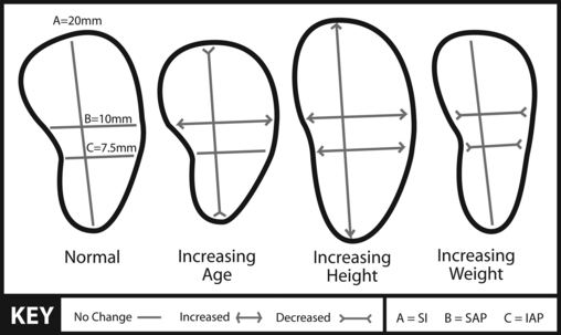
FIG. 2-22 Illustration demonstrating changes in IVF dimensions with increasing age, height, and weight. (From Cramer G et al. [2003]. Dimensions of the lumbar intervertebral foramina as determined from the sagittal plane magnetic resonance imaging scans of 95 normal subjects. J Manipulative Physiol Ther, 26, 160-170.)
The databases shown in the previous tables and figures may be used as a source of comparison when studying the IVF in healthy and diseased states such as suspected intervertebral foraminal stenosis (narrowing). Such stenosis can occur as the result of disc degeneration (Crock, 1976), ligamentum flavum hypertrophy, or Z joint arthrosis (i.e., increased bone formation because of increased weight-bearing or torsional stress). Of further interest to clinicians is the fact that the dimensions of the IVF have been found to be significantly related to anteroposterior vertebral canal diameters. However, transverse diameters of the vertebral canals and vertebral body heights do not correlate with IVF dimensions (Clarke et al., 1985). Clarke and colleagues (1985) speculate that prenatal and neonatal growth disruption may be a primary cause of abnormally small vertebral canal and IVF size. This remains an important area for future investigation.
Accessory Ligaments of the Intervertebral Foramen
Accessory ligaments of the IVF were first studied in the early nineteenth century (Bourgery, 1832). However, these structures received very little attention until the mid- to late-twentieth century, when Golub and Silverman (1969) first used the term transforaminal ligaments (TFLs) in the description of ligamentous bands crossing the IVFs. Since then, several investigators have studied these structures in the cervical (Bakkum & Berthiaume, 1994), thoracic (Bakkum & Mestan, 1994), and lumbar (Amonoo-Kuofi et al., 1988a,b; Nowicki & Haughton, 1992a,b; Bakkum & Mestan, 1994; Cramer et al., 2002) regions of the spine. These ligaments are much more common in the lower thoracic and lumbar regions (Bakkum & Mestan, 1994) than in the cervical region (Bakkum & Berthiaume, 1994), and are now considered to be normal structures within the lumbar IVFs. However, the reported incidence of TFLs in the lumbar region varies considerably (Table 2-8). One reason for the difference in reported findings is that there is considerable variation in size, shape, and location of TFLs from one IVF to another. Also some investigators evaluated different regions of the IVFs (i.e., medial, lateral, or both), and some authors only identified very thick and substantial structures as TFLs, whereas others were less restrictive in their definition of TFLs.
Table 2-8
Comparison of Results of Several Studies Evaluating Percentage of Intervertebral Foramina with Transforaminal Ligaments
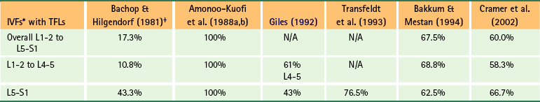
∗IVFs, Intervertebral foramina; TFLs, transforaminal ligaments.
†Very rigorous criteria.
From Cramer G et al. (2002). Evaluation of transforaminal ligaments by magnetic resonance imaging. J Manipulative Physiol Ther, 25, 199-208.
Amonoo-Kuofi and colleagues (1988a) also studied TFLs of the IVFs, and mapped out the relationship of the spinal nerve, segmental veins and arteries, and the recurrent meningeal nerve through the openings between the TFLs. They concluded that these accessory ligaments tend to hold the previously mentioned structures in their proper position within the IVF.
Transforaminal ligaments have been identified on both CT (Nowicki & Haughton, 1992b) and MRI scans (Nowicki & Haughton, 1992b; Cramer et al., 2002). Cramer and colleagues (2002) conducted a reliability study to evaluate the ability of trained radiologists to identify TFLs on MRI. The study was performed on cadaveric spines that were carefully dissected to identify all TFLs. The spines were then embedded in gelatin and MRI-scanned. Three radiologists were trained to identify TFLs on MRI scans and then evaluated the MRI scans of the cadaveric spines to determine the presence or absence of TFLs. The radiologists were blinded to the results of one another and to the anatomic specimens. The results showed that if a radiologist, trained to identify TFLs on MRI, determined that a TFL was present at a given IVF, there was approximately an 87% chance that one was actually present (i.e., a positive predictive value of 86.7%). However, if a trained radiologist stated a TFL was not present in an IVF, there remained approximately a 50% chance that one was present (i.e., a negative predictive value of 50.8%).
TFLs have been implicated as a cause of both low back pain and nerve root entrapment (Bachop & Janse, 1983; Giles, 1988; Macnab & McCulloh, 1990; Olsewski et al., 1991; Transfeldt, Robertson, & Bradford, 1993; Qian, Qin, & Zheng, 2011). Bakkum and Mestan (1994) found that when TFLs were present, the superior to inferior dimension of the compartment transmitting the anterior primary division of the spinal nerve was significantly decreased as compared with that of the osseous IVF (the mean decrease in size was 31.5%). They concluded that there is often less space at the exit zone of the IVF for the emerging anterior primary division than was traditionally considered to be the case. Furthermore, they felt that the decreased space may contribute to the incidence of neurologic symptoms in the region at times, especially after trauma or secondary to degenerative arthritic changes in the region of the IVF. Bachop and Janse (1983) reported that the higher a TFL is located within the IVF, the less space remains for the intervertebral vessels, which conceivably could lead to ischemia or venous congestion. They also postulated that lower placement of the ligament would increase the possibility of sensory and motor deficits. Qian and colleagues (2011) hypothesized that TFLs may be “the leading cause of lumbar nerve root compression in foraminal stenosis,” particularly in cases of IVD degeneration, where the narrowing IVD causes the IVF to narrow (become stenotic), positioning TFLs in the IVF closer to the exiting nerve roots and spinal nerve. Figure 2-23, A and B, shows examples of TFLs, and Figure 2-23, C, illustrates a composite drawing demonstrating the TFLs that have been reported in the literature.
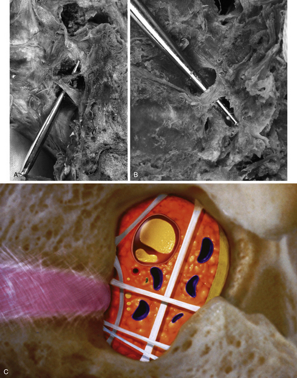
FIG. 2-23 Transforaminal ligaments (TFLs) in two different cadaveric specimens. A, Two TFLs coursing over a probe placed within the left L5-S1 intervertebral foramina (IVFs). Anteriorly, the two TFLs almost attach together onto the posterior aspect of the body of L5. Posteriorly, the two TFLs diverge, both attaching to the posterior border of the IVF. B, A different specimen. The probe is placed behind a broad flat TFL that is coursing from the body of L3 to the posterosuperior aspect of the IVF. The posterosuperior attachment is on the ligamentum flavum that is covering the junction of the superior and inferior articular processes of L3. C, A composite illustration demonstrating TFLs (white bands traversing intervertebral foramen in illustration) that have been reported in the literature. (From Cramer G et al. [2002]. Evaluation of transforaminal ligaments by magnetic resonance imaging. J Manipulative Physiol Ther, 25, 199-208.)
The term corporotransverse ligament is used when referring to a TFL that courses between the vertebral body and the transverse process at the L5-S1 junction (Bachop & Janse, 1983). The lumbar spinal ramus of the segmental artery, intervertebral veins, and gray sympathetic ramus course above this structure, and the anterior primary division courses underneath it (Golub & Silverman, 1969; Bachop & Ro, 1984).
Corporotransverse ligaments can be either broad and flat or rodlike (McNab, 1971; Bachop & Hilgendorf, 1981). The rodlike ligaments are usually tougher (firmer) than the flat type. Wang and colleagues (1999) found that corporotransverse ligaments have the histologic composition of other ligaments of the spine. In addition, calcification often is found in corporotransverse ligaments. Therefore the corporotransverse ligaments are sturdy ligamentous bands that can calcify (Wang et al., 1999).
Like TFLs, the corporotransverse ligaments can be seen on CT (Church & Buehler, 1991) and MRI (Nowicki & Haughton, 1992b; Cramer et al., 2002), but not on standard x-rays (Winterstein & Bachop, 1990). Figure 2-24 shows a corporotransverse ligament at the L5-S1 level of a cadaveric spine. Figure 2-25 shows two MRIs of the same cadaveric spine. The TFL is shown on the MRI of Figure 2-25, panel B.
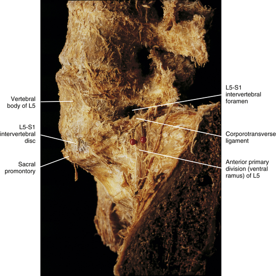
FIG. 2-24 Lateral view of a cadaveric lumbar spine. The red pins pass beneath a corporotransverse ligament that spans the left L5-S1 intervertebral foramen. Notice the anterior primary division (ventral ramus) passing beneath this ligament (between the red pins).
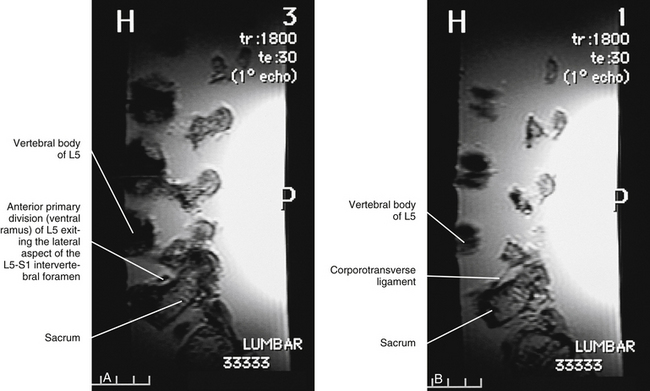
FIG. 2-25 Parasagittal magnetic resonance imaging scans of the same cadaveric spine shown in Figure 2-24. A, The anterior primary division (ventral ramus). B, Corporotransverse ligament in a scan lateral to that of A.
As with TFLs, the corporotransverse ligaments are also thought to be clinically significant. They may have a constricting effect on the anterior primary division (ventral ramus) because that nerve courses under the ligamentous band (McNab, 1971; Bachop & Janse, 1983). That is, in patients with sciatica, when the leg is raised, the anterior primary division could be stretched across the ligament, possibly mimicking the thigh and leg pain of a disc protrusion. In addition, Breig and Troup (1979) and Rydevik and colleagues (1984) have published information about the increased sensitivity of inflamed nerve roots. Factors such as facet arthrosis, disc protrusion, and ligamentum flavum hypertrophy could conceivably increase intraforaminal pressure. The presence of a corporotransverse ligament could further increase this pressure and possibly cause a subclinical problem to become clinical.
Other accessory ligaments of the spine that might impinge on nerves and blood vessels have been described by Bogduk (1981) and Nathan and colleagues (1982).
Advanced Diagnostic Imaging of the Spine
One of the most important clinical applications of the anatomy of the spine and spinal cord is in the field of advanced diagnostic imaging. The imaging modalities of CT and MRI frequently permit extremely clear visualization of the normal and pathologic anatomy of spinal structures. Examples of these images are included in other chapters to demonstrate various anatomic structures and to show how some of the structures discussed in the text appear on these images. A general understanding of the advantages and disadvantages of the most commonly used advanced imaging techniques helps the reader gain more information from these images. Therefore the first purpose of this section, which is written for those who do not specialize in diagnostic imaging, is to review the general application and uses of procedures. The second purpose is to describe the anatomic structures and spinal disorders that can best be imaged with a specific type of modality. Areas of relevant research also are discussed when the results affect currently used imaging procedures. The final purpose is to provide a brief review of the literature for the student, clinician, and researcher whose major field is not related to diagnostic imaging. Because most of the principles discussed in this section are applicable to all spinal regions, diagnostic imaging included in this chapter is related to general characteristics of the spine rather than to specific spinal regions, which are discussed later in the text.
Because the advanced imaging modalities most commonly used are MRI and CT, the majority of this review discusses these two imaging modalities. Other methods, including ultrafine flexible fiberoptic scopes, myelography, discography, angiography, ultrasonography, three-dimensional computed tomography, radionuclide imaging, and digital imaging, also are discussed.
Magnetic Resonance Imaging
MRI is an important component of spinal imaging. MRI shows soft tissue especially well and represents a quantum leap in the evaluation of patients with disc disease (Woodruff, 1988). It has been found to be more sensitive than contrast-enhanced CT in demonstrating disc degeneration (Schnebel et al., 1989), and is currently the imaging modality of choice in the evaluation of lumbar disc protrusion and extrusion (Forristall, Marsh, & Pay, 1988; Jackson et al., 1989). MRI can also detect some tears of the AF (Herzog, 1996). However, MRI alone is not enough to determine the cause of back pain (Borenstein et al., 2001), and correlations with patient history, physical examination findings, and (if necessary) findings of laboratory and other diagnostic procedures (e.g., electromyography) are essential to establish the most likely cause of back pain.
MRI also can detect disruption of the posterior longitudinal ligament secondary to extrusion of the NP. MRI not only allows for visualization of the discs, cerebrospinal fluid, spinal cord, and the perimeter of the spinal canal, but also allows visualization of these structures in several planes without the use of intravenous contrast media. For these reasons MRI is currently the method of choice for detecting disorders of the spinal canal and spinal cord (Woodruff, 1988) and can detect spinal cord injury without radiographic abnormalities (SCIWORA syndrome) (Kasimatis et al., 2008). Edema of bone marrow, spinal cord tumors, syringomyelia, extramedullary tumors (e.g., meningiomas), early detection of metastatic disease and primary malignancies of the vertebrae, and spina bifida (dysraphism) are all evaluated exceptionally well with this technology (Alexander, 1988; Woodruff, 1988; An et al., 1995; Buckwalter & Brandser, 1997). MRI also has been found to be effective in the evaluation of failed back surgery syndrome by differentiating fibrotic scar formation secondary to spinal surgery from disc herniation (Frocrain et al., 1989; Kricun, Kricun, & Danlinka, 1990) and is becoming the most important modality for all imaging of the postoperative spine (Djukic et al., 1990). Discitis also can be evaluated with MRI (Woodruff, 1988). MRI and conventional films are considered adequate for the preneurosurgical evaluation of cervical radiculopathy and myelopathy, with CT myelography being the follow-up procedure of choice (Brown et al., 1988).
A discrete area of high signal, known as a “high-intensity zone,” has been identified as a marker for painful tears of the outer AF of the IVD, especially tears related to internal disc disruption (Aprill & Bogduk, 1992; Schellhas et al., 1996a,b). (See Chapter 11 for a discussion of internal disc disruption.) Perhaps a related finding is that the high-intensity zone also has been associated with decreased stiffness of the IVD, especially in axial rotation (Schmidt et al., 1998). Saifuddin, McSweeney, and Lehovsky (2003) found that the high-intensity zone became more apparent when MRI scans were taken during axial loading of the spine (loads causing compression of the IVDs; e.g., standing). However, other research questions the clinical relevance of the high-intensity zone (Narvani, Tsiridis, & Wilson, 2003).
MRI continues to be a rapidly developing field, and the many technical advances should continue to improve its clinical utility. One such advance is the ability to decrease cerebrospinal fluid (CSF) flow artifact. This development results in better visualization of the spinal cord and the cord–CSF interface. Other advances are related to an increased variety of new imaging protocols used by radiologists. The imaging protocols of gradient-echo imaging (e.g., GRASS, FLASH, FISP, MPGR) allow for greater contrast between anatomic structures while decreasing scan time. Such gradient-echo techniques are the procedures of choice in patients with suspected cervical radiculopathy (Kricun, Kricun, & Danlinka, 1990), giving information of greater or equal value to that obtained from myelography or CT myelography (Hedberg, Dayer, & Flom, 1988). In addition, diffusion-weighted MR imaging allows for visualization of the nerve roots, spinal nerve, formation of the plexuses, and proximal aspects of peripheral nerves (Tsuchiya et al., 2007).
Two of the primary properties of MR images are related to the various responses of different tissues to the radiofrequency applied during the MRI evaluation. These two characteristics are known as T1 and T2. Various MRI protocols can highlight either of these characteristics and thereby selectively enhance different tissues. T1-weighted images are better for depicting anatomic detail. Adipose tissue has a high signal (is bright) on T1-weighted images, and these images are particularly useful in the evaluation of the spinal cord, bone marrow of vertebrae, IVDs, osteophytes, and ligaments (Woodruff, 1988; Kricun, Kricun, & Danlinka, 1990).
As a result of the increased acquisition time of the second echo, the resolution of T2-weighted images is not as good as that of T1-weighted images. However, T2-weighted images allow for better visualization of fluid and edema, and often reveal subtle, significant spinal cord pathology. T2-weighted images are also the most sensitive at showing a decreased signal intensity resulting from degeneration and desiccation of the disc (Woodruff, 1988; Herzog, 1996), and a decreased signal of the IVD on T2-weighted images may either precede or follow histologic evidence of IVD degeneration (Herzog, 1996). Because CSF has a very high signal on T2-weighted images, these images also are valuable in evaluating the amount of narrowing of the subarachnoid space in cases of spinal stenosis. T2-weighted images also create a “myelographic effect” related to the bright appearance of CSF on these films. This myelographic effect can help with the detection and characterization of subtle disc bulges and protrusions. T2-weighted images also are useful in the detection of multiple myeloma of the vertebral column (Avrahami, Tadmor, & Kaplinsky, 1993). Even with all of these advantages, in general, T1-weighted images are more valuable than T2-weighted images in the evaluation of the majority of spinal disorders (Moffit et al., 1988).
The contrast medium of gadolinium-diethylenetriaminepentaacetic acid (Gd-DTPA) can be used in conjunction with MRI and has been found to be safe and effective in increasing the contrast of certain pathologic conditions. Differentiation of scar formation (epidural fibrosis) from disc herniation in failed back surgery syndrome (recurrent postoperative sciatica) is improved with the use of Gd-DTPA (Hueftle et al., 1988). Gd-DTPA also may be useful in depicting disc protrusions and extrusions surrounded by scar tissue and free disc fragments. It also can be useful in identifying acute healing compression fractures and differentiating whether a compression fracture of the vertebral body is the result of a benign or malignant process. Gd-DTPA also is useful in evaluating patients with intradural tumors, but it is less useful in evaluating tumors external to the dura mater.
Magnetic resonance angiography (MRA) allows for imaging of arterial vasculature and is being used extensively in spinal imaging to assess the vertebrobasilar arterial system. In addition, Mordasini and colleagues (2012) used a high-field strength magnet (3 tesla [T]) to image the great radiculomedullary artery (of Adamkiewicz) in preparation for thoracoabdominal aortic aneurysm repair surgery. Advances in high-field strength MRA may allow for even more detailed assessment of spinal vasculature in the future.
Advances in MRI technology include developments in the hardware of the MRI unit, such as coil configurations (Woodruff, 1988). These changes allow large areas of the spine to be viewed at once, which is particularly useful in the evaluation of metastatic disease and syringomyelia. Other advances include three-dimensional reconstruction of spinal images with a video display that allows images to be rotated 360 degrees for viewing. Axial loaded (standing) MRI of the lumbar spine, which images the spine in a more physiologic state, may help to more accurately assess the dimensions of the spinal canal, when compared with routinely performed supine examinations with the hips and knees flexed (Saifuddin, Blease, & McSweeney, 2003). In addition, functional MRI (fMRI) evaluation of the spinal cord, which maps MRI signal changes after a specific stimulus designed to change neural activity, may become fundamental in the future work-up of spinal cord injury (Stroman et al., 2002).
Research is also being done involving morphometry of the spine by means of MRI (Cramer et al., 2003). Morphometry means the measurement of an organism or its parts. The digital images available from MRI (and CT) scans may be used to accurately quantify certain anatomic structures of the spine. This is the first time many such measurements can be made in living patients. Such measurements allow for an increased ability to study the structures influenced by a variety of therapeutic procedures (Cramer et al., 2002, 2003, 2012).
Diffusion and perfusion MRI allows information to be gained about the structure and function of tissue at a microscopic level. These procedures have an increasingly prominent clinical role, especially in neurovascular imaging (Valentini et al., 2003). Finally, extraordinary opportunities for advances in the clinical applications of MRI exist as imaging at the molecular level becomes possible (Rollo, 2003). Advances in spinal research will undoubtedly make use of such important applications as the imaging of the chemical mediators of back pain. (See Chapter 11 for a discussion of these chemical mediators.)
Computed Tomography
Conventional CT remains effective in the evaluation of many conditions. It is especially valuable when accurate depiction of osseous tissues is important. Pathologic conditions including spinal stenosis, bone tumors, congenital anomalies, degenerative changes, trauma, spondylolysis, and spondylolisthesis can all be accurately evaluated by CT (Wang, Wesolowski, & Farah, 1988). Images reformatted to the sagittal or coronal plane may help with the evaluation of complicated bone anatomy. Arachnoiditis ossificans, a rare ossification of the arachnoid mater as a consequence of trauma, hemorrhage, previous myelogram, or spinal anesthesia, can be better visualized on CT than MRI (Wang, Wesolowski, & Farah, 1988). Criteria for the diagnosis of intraspinal hemangiomas by means of CT also have been established (Salamon & Freilich, 1988). Although lumbar disc disease can be evaluated adequately by means of CT, “beam hardening” artifacts lead to inadequate evaluation of disc disease in the thoracic and, to a lesser extent, the lower cervical canal (Woodruff, 1988).
CT is especially valuable in the evaluation of lumbar spinal stenosis, although artifacts sometimes make the evaluation of cervical and thoracic spinal stenosis difficult (Wang, Wesolowski, & Farah, 1988). The evaluation of facet joint disease and calcification of the ligamentum flavum is currently more efficient with CT than with MRI (Wang, Wesolowski, & Farah, 1988).
CT is also quite effective in the evaluation of bone destruction and new bone formation secondary to neoplasia. It demonstrates the vertebral bony cortex and vertebral bodies well (Buckwalter & Brandser, 1997). In addition, CT is excellent in allowing the identification of osseous changes subsequent to spinal trauma. For example, CT is particularly good at identifying the presence of bony fragments in the spinal canal after posterior arch fracture (Wang, Wesolowski, & Farah, 1988).
Intrathecal contrast-enhanced CT (CT myelography) results in a more complete depiction of the spinal canal, the IVD relative to the spinal canal, and the perimeter of the spinal cord (Woodruff, 1988). Contrast-enhanced CT and MRI are comparable in their abilities to demonstrate spinal stenosis (Schnebel et al., 1989). CT and MRI have a complementary role in the evaluation of such disorders as spinal canal stenosis, congenital disorders, facet disorders, and acute spinal injury (Wang, Wesolowski, & Farah, 1988; Tracy, Wright, & Hanigan, 1989). Extraforaminal (far lateral and anterior) disc herniations can also be readily identified on both CT and MRI if scans include L2 through S1, and if the IVF and paravertebral spaces are closely examined (Osborn et al., 1988).
Other Imaging Modalities
Ultrafine Flexible Fiberoptic Scopes
Ultrafine flexible fiberoptic scopes (“fiberscopes”) have been used to provide direct visualization of the epidural space and the subarachnoid space with exceptional clarity of visual detail. In fact, using fiberscopes, Tobita and colleagues (2003) made new diagnoses in 12 of 55 chronic low back pain subjects who had previously been imaged with other advanced diagnostic procedures. The most common new diagnosis was chronic arachnoiditis.
Myelography
Myelography is the injection of radiopaque dye into the subarachnoid space of the lumbar cistern followed by spinal x-ray examinations. Myelography for the evaluation of lumbar disc herniation is rapidly being replaced by CT and MRI. However, it may be useful when the level of the lesion is clinically unclear or when the entire lumbar region and thoracolumbar junction are to be examined (Fagerlund & Thelander, 1989).
Discography
Discography is the injection of radiopaque dye into the IVD. This technique is useful as an adjunct in the evaluation of symptomatic disorders of the disc. Discography in conjunction with CT (CT/discography) allows delineation and classification of anular disc disruption not possible with plain discography (i.e., discography used in conjunction with conventional radiographs) and, in some cases, identifies such disruption when not seen on T2-weighted MR images. Discography may be particularly useful in evaluating chronic low back pain patients with suspected disc disorders (McFadden, 1988; Herzog, 1994) when the patient’s pain is at a significant level of intensity (stress discography). Although discography remains a controversial diagnostic procedure, current literature supports the use of discography in select situations (Guyer & Ohnmeiss, 2003).
Angiography
Spinal angiography is the imaging of the vasculature after the injection of a radiopaque contrast medium. This technique is used to evaluate the arterial supply of spinal tumors (e.g., aneurysmal bone cyst) to assist the surgeon in operative planning (Wang, Wesolowski, & Farah, 1988). Magnetic resonance angiography (see above) is gaining widespread use in the evaluation of spinal and intracranial vascular pathology.
Ultrasonography
Ultrasonography (sonography) is currently being used in the evaluation of posterior arch defects in spina bifida (dysraphism), in the intraoperative and postoperative evaluation of the spinal cord, and in the evaluation of the fetal and neonate spine (Wang, Wesolowski, & Farah, 1988). Three-dimensional ultrasound is becoming an important adjunct imaging procedure in this regard as well. This technique has the ability to show the alignment of the posterior spinal elements and the integrity of the vertebral bodies (Hughes et al., 2003). Ultrasound is also useful in the evaluation of tumors of the cauda equina (Friedman, Wetjen, & Atkinson, 2003).
Three-Dimensional Computed Tomography
Three-dimensional CT uses the digital data obtained from conventional CT and reprocesses the information to create a three-dimensional display that can be rotated 360 degrees on a video console. This technique is useful as an adjunct to conventional CT in the evaluation of complex spinal fractures, spondylolisthesis, postoperative fusion, and in some cases of spinal stenosis (Pate, Resnick, & Andre, 1986). Three-dimensional CT is excellent for the assessment of degenerative stenosis of the vertebral canal, lateral recess stenosis, and foraminal stenosis (Krupski et al., 2002).
Radionuclide Imaging
Single photon emission CT (SPECT) uses tomographic slices obtained with a gamma camera to evaluate radionuclide uptake. This modality has been shown to be a useful adjunct to planar bone scintigraphy (i.e., bone scans, which are very effective in identifying primary and metastatic neoplasia of bone) in the identification and localization of spinal lesions, especially those responsible for low back pain (Kricun, Kricun, & Danlinka, 1990). SPECT is also effective in the evaluation of spondylolysis. Positron emission tomography (PET) is useful in the differentiation of degenerative and infectious end plate abnormalities in the lumbar spine (Stumpe et al., 2002), and is becoming an important physiologic imaging modality in the staging of malignant tumors and for the monitoring of the results of cancer therapy (Jerusalem et al., 2003).
Digital Imaging
Digital imaging uses a conventional x-ray source and a very efficient x-ray detector to digitize and immediately obtain images. This technique is being used currently in the follow-up evaluation of scoliosis because of its relatively small radiation dose. However, because of the lack of adequate spatial resolution, conventional radiographs should be used at the initial evaluation of scoliosis with osseous etiologic components, such as congenital anomalies (Kushner & Cleveland, 1988; Kricun, Kricun, & Danlinka, 1990). Imaging applications of all types are rapidly becoming digitally based. Digitally based imaging aids in the rapid transport of images for interpretation and also reduces the space and cost of archiving images.
References
Adams, M. Pathophysiology of disc degeneration. In: Haldeman S., ed. Principles and practice of chiropractic. ed 3. New York: McGraw-Hill Companies; 2005:383–400.
Ahmed, M., et al. Sensory and autonomic innervation of the facet joint in the rat lumbar spine. Spine. 1993;18:2121–2126.
Alexander, A. Magnetic resonance imaging of the spine and spinal cord tumors. In: Bisese J.H., ed. diagnostic and therapeutic applications: Spine, state of the art reviews, spinal imaging. Philadelphia: Hanley & Belfus, 1988.
Alexander, L.A., et al. The response of the nucleus pulposus of the lumbar intervertebral discs to functionally loaded positions. Spine (Phila Pa 1976). 2007;32:1508–1512.
Amonoo-Kuofi, H.S., et al. Ligaments associated with lumbar intervertebral foramina. I. L1 to L4. J Anat. 1988;156:177–183.
Amonoo-Kuofi, H.S., et al. Ligaments associated with lumbar intervertebral foramina. II. The fifth lumbar level. J Anat. 1988;159:1–10.
An, H.S., et al. Can we distinguish between benign versus malignant compression fractures of the spine by magnetic resonance imaging? Spine. 1995;20:1776–1782.
Aprill, C., Bogduk, N. High-intensity zone: a diagnostic sign of painful lumbar disc on magnetic resonance imaging. Br J Radiol. 1992;65:361–369.
Avrahami, E., Tadmor, R., Kaplinsky, N. The role of T2 weighted gradient echo in MRI demonstration of spinal multiple myeloma. Spine. 1993;18:1812–1815.
Awalt, P., et al. Radiographic measurements of intervertebral foramina of cervical vertebra in forward and normal head posture. J Craniomand Pract. 1989;7:275–285.
Bachop, W., Hilgendorf, C. Transforaminal ligaments of the human lumbar spine. Anat Rec. 199, 1981. [(abstract)].
Bachop, W., Janse, J. The corporotransverse ligament at the L5 intervertebral foramen. Anat Rec. 205, 1983. [(abstract)].
Bachop, W.E., Ro, C.S. A ligament separating the nerve from the blood vessels at the L5 intervertebral foramen. Orthopaedic Transactions. 1984;8:437.
Bahk, Y.W., Lee, J.M. Measure-set computed tomographic analysis of internal architectures of lumbar disc: clinical and histologic studies. Invest Radiol. 1988;23:17–23.
Bailey, P., Casamajor, L. Osteo-arthritis of the spine as a cause of compression of the spinal cord and its roots. J Nerve Ment Dis. 1911;38:588–609.
Bailey, C.S., Sjovold, S.G., Dvorak, M.F., et al. The strength profile of the thoracolumbar endplate reflects the sagittal contours of the spine. Spine (Phila Pa 1976). 2011;36:124–128.
Bakkum, B.W., Berthiamue, B. Transforaminal ligaments of the human cervical spine. Proceedings of the Eleventh Annual Meeting of the American Association of Clinical Anatomists. 22, 1994.
Bakkum, B.W., Mestan, M. The effects of transforaminal ligaments on the sizes of T11 to L5 human intervertebral foramina. J Manipulative Physiol Ther. 1994;17:517–522.
Bayliss, M., et al. Proteoglycan synthesis in the human intervertebral disc: variation with age, region, and pathology. Spine. 1988;13:972–981.
Beaman, D.N., et al. Substance P innervation of lumbar spine facet joints. Spine. 1993;18:1044–1049.
Black, K.M., McClure, P., Polansky, M. The influence of different sitting positions on cervical and lumbar posture. Spine. 1996;21:65–70.
Bogduk, N. The lumbar mamillo-accessory ligament: its anatomical and neurosurgical significance. Spine. 1981;6:162–167.
Bogduk, N. Clinical anatomy of the lumbar spine, ed 4. London: Churchill Livingstone; 2005.
Bogduk, N. Diagnostic blocks. In: Clark C.R., ed. The cervical spine. ed 4. Philadelphia: Lippincott Williams & Wilkins; 2005:255–260.
Bogduk, N., Engel, R. The menisci of the lumbar zygapophyseal joints. Spine. 1984;9:454–460.
Bodguk, N., Tynan, W., Wilson, A. The nerve supply to the human lumbar intervertebral discs. J Anat. 1981;132:39–56.
Boelderl, A., et al. Danger of damaging the medial branches of the posterior rami of spinal nerves during a dorsomedian approach to the spine. Clin Anat. 2002;15:77–81.
Boos, N., et al. A new magnetic resonance imaging analysis method for the measurement of disc height variations. Spine. 1996;21:563–570.
Boos, N., et al. Classification of age-related changes in lumbar intervertebral discs: 2002 Volvo award in basic science. Spine. 2002;27:2631–2644.
Borenstein, D.G., et al. The value of magnetic resonance imaging of the lumbar spine to predict low-back pain in asymptomatic subjects. J Bone Joint Surg. 2001;83a:1306–1311.
Boszczyk, B.M., et al. Related an immunohistochemical study of the dorsal capsule of the lumbar and thoracic facet joints. Spine. 2001;26(15):E338–E343.
Botsford, D.J., Esses, S.I., Olgilvie-Harris, D.J. In vivo diurnal variation in intervertebral disc volume and morphology. Spine. 1994;19:935–945.
Bourgery, J. Traite commplet de l'anatomie del'homme, comprenant la medicine operatiore. Tome 1.C. Paris: Delauney; 1832. [449–450].
Breger, R., et al. Truncation artifact in MR images of the intervertebral disc. AJRN. 1988;9:825–828.
Breig, A., Troup, J. Biomechanical considerations in the straight leg raising test. Spine. 1979;4:242–250.
Brønfort, G. Efficacy of manual therapies of the spine. Amsterdam: Thesis Publishers Amsterdam; 1997.
Brown, B.M., et al. Preoperative evaluation of cervical radiculopathy and myelopathy by surface-coil MRI imaging. AJR, Am J Roentgenol. 1988;151:1205–1212.
Buckwalter, J., et al. Articular cartilage and intervertebral disc proteoglycans differ in structure: an electron microscopic study. J Orthop Res. 1989;7:146–151.
Buckwalter, J.A., Brandser, E.A. Metastatic disease of the skeleton. Am Fam Physician. 1997;55:1761–1768.
Cavanaugh, J.M., et al. Lumbar facet pain: biomechanics, neuroanatomy and neurophysiology. J Biomech. 1996;29(9):1117–1129.
Cavanaugh, J.M., et al. Mechanisms of low back pain: a neurophysiologic and neuroanatomic study. Clin Orthop. 1997;335:166–180.
Cavanaugh, J.M., Kallakuri, S., Özaktay, A.C. Innervation of the rabbit lumbar intervertebral disc and posterior longitudinal ligament. Spine. 1995;20:2080–2085.
Chadha, M., et al. Pedicle morphology of the lower thoracic, lumbar, and S1 vertebrae: an Indian perspective. Spine. 2003;28:744–749.
Chaynes, P., et al. Microsurgical anatomy of the internal vertebral venous plexuses. Surg Radiol Anat. 1998;20:47–51.
Chen, K.P., et al. The depth of the epidural space. Anaesth Sinica. 1989;27:353–356.
Cheng, X.G., et al. Radiological prevalence of lumbar intervertebral disc calcification in the elderly: an autopsy study. Skeletal Radiol. 1996;25:231–235.
Church, C.P., Buehler, M.T. Radiographic evaluation of the corporotransverse ligament at the L5 intervertebral foramen: a cadaveric study. J Manipulative Physiol Ther. 1991;14(4):240–248.
Clarke, G.A., et al. Can infant malnutrition cause adult vertebral stenosis? Spine. 1985;10:165–170.
Coppes, M.H., et al. Innervation of “painful” lumbar discs. Spine. 1997;22:2342–2349.
Coventry, M.B. Anatomy of the intervertebral disc. Clin Orthop. 1969;67:9–15.
Cramer, G., et al. Comparative evaluation of the lumbar intervertebral foramen by computed tomography and magnetic resonance imaging. Clin Anat. 1992;5:238.
Cramer, G., et al. Dimensions of the lumbar intervertebral foramina as determined from the sagittal plane magnetic resonance imaging scans of 95 normal subjects. J Manipulative Physiol Ther. 2003;26:160–170.
Cramer, G.D., et al. Effects of side-posture positioning and side-posture adjusting on the lumbar zygapophysial joints as evaluated by magnetic resonance imaging: a before and after study with randomization. J Manipulative Physiol Ther. 2000;23:380–394.
Cramer, G.D., et al. Evaluation of transforaminal ligaments by magnetic resonance imaging. J Manipulative Physiol Ther. 2002;25:199–208.
Cramer, G.D., et al. Degenerative changes following spinal fixation in a small animal model. J Manipulative Physiol Ther. 2004;27:141–154.
Cramer, G.D., et al. Quantification of cavitation and gapping of lumbar zygapophyseal joints during spinal manipulative therapy. J Manipulative Physiol Ther. 2012. [(in press)].
Crock, H.V. Isolated lumbar disk resorption as a cause of nerve root canal stenosis. Clin Orthop. 1976;115:109–115.
Crock, H.V., Yoshizawa, H. The blood supply of the lumbar vertebral column. Clin Orthop. 1976;115:6–21.
Croft, A.C. Whiplash and mild traumatic brain injuries. Coronado: Spine Research Institute of San Diego Press; 2009.
Curylo, L.J., et al. Segmental variations of bone mineral density in the cervical spine. Spine. 1996;21:319–322.
Czervionke, L., et al. Cervical neural foramina: correlative anatomic and MR imaging study. Radiology. 1988;169:753–759.
Datta, S., et al. Systematic assessment of diagnostic accuracy and therapeutic utility of lumbar facet joint interventions. Pain Physician. 2009;12:437–460.
Djukic, S., et al. Magnetic resonance imaging of the postoperative lumbar spine. Radiol Clin North Am. 1990;28:341–360.
Domisse, G.F., Louw, J.A. Anatomy of the lumbar spine. In: Floman Y., ed. Disorders of the lumbar spine. Rockville, Md: Aspen Publishers, 1990.
Dreyer, S.J., Dreyfuss, P.H. Low back pain and the zygapophysial (facet) joints. Arch Phys Med Rehabil. 1996;77:290–300.
Dreyfuss, P., et al. Efficacy and validity of radiofrequency neurotomy for chronic lumbar zygapophysial joint pain. Spine (Phila Pa 1976). 2000;25:1270–1277.
Dreyfuss, P., et al. The significance of multifidus atrophy after successful radiofrequency neurotomy for low back pain. PMR. 2009;1:719–722.
Edelson, J.G., Nathan, H. Stages in the natural history of the vertebral end plates. Spine. 1988;13:21–26.
Edgar, M.A. The nerve supply of the lumbar intervertebral disc. J Bone Joint Surg Br. 2007;89:1135–1139.
Edgar, M., Ghadially, J. Innervation of the lumbar spine. Clin Orthop. 1976;115:35–41.
Edwards, W.T., et al. Peak stresses observed in the posterior lateral annulus. Spine. 2001;26:1753–1759.
Engel, R., Bogduk, N. The menisci of the lumbar zygapophysial joints. J Anat. 1982;135:795–809.
Esses, S.I., Moro, J.K. Intraosseous vertebral body pressures. Spine. 1992;17:s155–s159.
Fagerlund, M.K.J., Thelander, U.E. Comparison of myelography and computed tomography in establishing lumbar disc herniation. Acta Radiol. 1989;30:241–246.
Fardon, D.F. The name of the ring. Spine. 1988;13:713–715.
Fardon, D.F. Nomenclature and classification of lumbar disc pathology. Spine (Phila Pa 1976). 2001;26:461–462.
Feltrin, G.P., et al. Fractal analysis of lumbar vertebral cancellous bone architecture. Clin Anat. 2001;14:414–417.
Fennell, A.J., Jones, A.P., Hukins, D.W.L. Migration of the nucleus pulposus within the intervertebral disc during flexion and extension of the spine. Spine. 1996;21:2753–2757.
Fesmire, F., Luten, R. The pediatric cervical spine: development anatomy and clinical aspects. J Emerg Med. 1989;7:133–142.
Forristall, R., Marsh, H., Pay, N. Magnetic resonance imaging and contrast CT of the lumbar spine: comparison of diagnostic methods of correlation with surgical findings. Spine. 1988;13:1049–1054.
Friedman, J.A., Wetjen, N.M., Atkinson, J.L. Utility of intraoperative ultrasound for tumors of the cauda equine. Spine. 2003;28:288–291.
Frocrain, L., et al. Recurrent postoperative sciatica: evaluation with MR imaging and enhanced CT. Radiology. 1989;170:531–533.
Fujiwara, A., et al. The effect of disc degeneration and facet joint osteoarthritis on the segmental flexibility of the lumbar spine. Spine. 2000;25:3036–3044.
Giles, L.G. Human zygapophyseal joint inferior recess synovial folds: a light microscopic examination. Anat Rec. 1988;220:117–124.
Giles, L.G. The surface lamina of the articular cartilage of human zygapophyseal joints. Anat Rec. 1992;233:350–356.
Giles, L.G., Taylor, J.R. Human zygapophyseal joint capsule and synovial fold innervation. Br J Rheumatol. 1987;26:93–98.
Giles, L.G.F. Mechanisms of neurovascular compression within the spinal and intervertebral canals. J Manipulative Physiol Ther. 2000;23:107–111.
Gilsanz, V. Vertebral bone density in children: effects of puberty. Radiology. 1988;166:847–850.
Gilsanz, V., et al. Peak trabecular vertebral density: a comparison of adolescent and adult females. Calcif Tissue Int. 1988;43:260–262.
Golub, B., Siverman, B. Transforaminal ligaments of the lumbar spine. J Bone Joint Surg. 1969;51:947–956.
Grosland, N.M., Goel, V.K. Vertebral endplate morphology follows bone remodeling principles. Spine (Phila Pa 1976). 2007;32:E667–E673.
Guehring, T., et al. Disc distraction shows evidence of regenerative potential in degenerated intervertebral discs as evaluated by protein expression, magnetic resonance imaging, and messenger ribonucleic acid expression analysis. Spine (Phila Pa 1976). 2006;31:1658–1665.
Guehring, T., et al. Intradiscal pressure measurements in normal discs, compressed discs and compressed discs treated with axial posterior disc distraction: an experimental study on the rabbit lumbar spine model. Eur Spine J. 2006;15:597–604.
Guyer, R.D., Ohnmeiss, D.D. Lumbar discography. Spine J. 2003;3(suppl 3):s11–s27.
Hackney, D.B. Normal anatomy. Top Magn Reson Imaging. 1992;4:1–6.
Hadley, L. Intervertebral foramen constriction. JAMA. 1949;140:473–476.
Hadley, L.A. Apophysial subluxation. J Bone Joint Surg. 1948:428–433.
Haher, T.R., et al. Instantaneous axis of rotation as a function of the three columns of the spine. Spine. 1992;17:s149–s154.
Harrison, D.E., Harrison, D.D., Troyanovich, S.J. Three-dimensional spinal coupling mechanics: Part 1. A review of the literature. J Manipulative Physiol Ther. 1998;21:101–113.
Hasue, M., et al. Anatomic study of the interrelation between lumbosacral nerve roots and their surrounding tissues. Spine. 1983;8:50–58.
Hedberg, M.C., Dayer, B.P., Flom, R.A. Gradient echo (GRASS) MR imaging in cervical radiculopathy. AJNR. 1988;9:145–151.
Hee, H.T., Zhang, J., Wong, H.K. An in vitro study of dynamic cyclic compressive stress on human inner annulus fibrosus and nucleus pulposus cells. Spine J. 2010;10:795–801.
Herkowitz, H.N., et al. Discussion on cigarette smoking and the prevalence of spinal procedures. J Spin Disord. 1992;5:135–136.
Herzog, R.J. Imaging corner: the goal of spinal imaging. Spine. 1994;19:2486–2488.
Herzog, R.J. The radiologic assessment for a lumbar disc herniation. Spine. 1996;21:S19–S38.
Hewitt, W. The intervertebral foramen. Physiotherapy. 1970;56:332–336.
Hickey, D.S., Hukins, D.W.L. Relation between the structure of the annulus fibrosus and the function and failure of the intervertebral disc. Spine. 1980;5:106–116.
Ho, P.S.P., et al. Progressive and regressive changes in the nucleus pulposus. Part I. The neonate. Radiology. 1988;169:87–91.
Holm, S., Nachemson, A. Variations in the nutrition of the canine intervertebral disc induced by motion. Spine. 1983;8:866–874.
Hueftle, M., et al. Lumbar spine: postoperative MR imaging with Gd-DTPA. Radiology. 1988;167:817–824.
Hughes, J.A., et al. Three-dimensional sonographic evaluation of the infant spine: preliminary findings. J Clin Ultrasound. 2003;31:9–20.
Humzah, M.D., Soames, R.W. Human intervertebral disc: structure and function. Anat Rec. 1988;220:337–356.
Iatridis, J.C., et al. Is the nucleus pulposus a solid or a fluid? Mechanical behaviors of the nucleus pulposus of the human intervertebral disc. Spine. 1996;21:1174–1184.
Isherwood, I., Antoun, N.M. CT scanning in the assessment of lumbar spine problems. In Jayson M., ed.: The lumbar spine and back pain, 2nd ed., London: Pitman Publishing, 1980.
Issever, A.S., et al. Micro-computed tomography evaluation of trabecular bone structure on loaded mice tail vertebrae. Spine. 2003;28:123–128.
Ito, S., et al. An observation of ruptured annulus fibrosus in lumbar discs. J Spine Disord. 1991;4:462–466.
Jackson, R., et al. The neuroradiographic diagnosis of lumbar herniated nucleus pulposes. II. A comparison of computed tomography (CT), myelography, CT-myelography, and magnetic resonance imaging. Spine. 1989;14:1362–1367.
Jayson, M. The lumbar spine and back pain, ed 2. Baltimore: Urban & Schwarzenberg and Pitman Medical Publishing; 1980.
Jeffries, B. Facet joint injections. Spine State Art Rev. 1988;2:409–417.
Jerusalem, G., et al. PET scan imaging in oncology. Eur J Cancer. 2003;39:1525–1534.
Jiang, H. Identification of the location, extent, and pathway of sensory neurologic feedback after mechanical stimulation of a lateral spinal ligament in chickens. Spine. 1997;22(1):17–25.
Johnson, W.E.B., et al. Immunohistochemical detection of Schwann cells in innervated and vascularized human intervertebral discs. Spine. 2001;26:2550–2557.
Kasimatis, G.B., et al. The adult spinal cord injury without radiographic abnormalities syndrome: magnetic resonance imaging and clinical findings in adults with spinal cord injuries having normal radiographs and computed tomography studies. J Trauma. 2008;65:86–93.
Kim, J.Y., Nah, K.S. Prediction of osteoporosis using fractal analysis et cetera on panoramic radiographs. Korean J Oral Maxillofac Radiol. 2007;37:79–82.
Korecki, C.L., MacLean, J.J., Iatridis, J.C. Dynamic compression effects on intervertebral disc mechanics and biology. Spine (Phila Pa 1976). 2008;33:1403–1409.
Kos, J. Contribution a l'etude de l'anatomie et de la vascularisation des ariticulations intervertebrales. Bull Assoc Anatomistes. 1969;142:1088–1105.
Kos, J., Wolf, J. Les menisques intervertebraux et le role possible dans les blocages vertebraux (translation). J Orthop Sports Phys Ther. 1972;1:8–9.
Kraemer, J. Presidential address: natural course and prognosis of intervertebral disc diseases. Spine. 1995;20:635–639.
Kraemer, J., et al. Water and electrolyte content of human intervertebral discs under variable load. Spine. 1985;10:69–71.
Kricun, R., Kricun, M., Danlinka, M. Advances in spinal imaging. Radiol Clin North Am. 1990;28:321–339.
Krismer, M., et al. Motion in lumbar functional spine units during side bending and axial rotation moments depending on the degree of degeneration. Spine. 2000;25:2020–2027.
Krupski, W., et al. Degenerative changes of the vertebral column in spatial imaging of 3D computed tomography. Ann Univ Mariae Curie Sklodowska. 2002;57:459–465.
Kuga, N., Kawabuchi, M. Histology of intervertebral disc protrusion: an experimental study using an aged rat model. Spine. 2001;26(17):E379–E384.
Kushner, D.C., Cleveland, R.H. Digital imaging in scoliosis. In: Kricun M.E., ed. Imaging modalities in spinal disorders. Philadelphia: WB Saunders, 1988.
Lancourt, J.E., Glenn, W.V., Wiltse, L.L. Multiplanar computerized tomography in the normal spine and in the diagnosis of spinal stenosis: a gross anatomic-computerized tomographic correlation. Spine. 1979;4:379–390.
LeBlanc, A.D., et al. The spine: changes in T2 relaxation times from disuse. Radiology. 1988;169:105–107.
Leboeuf-Yde, C., Yashin, A. Smoking and low back pain: is the association real? J Manipulative Physiol Ther. 1995;18:457–463.
Ledsome, J.R., et al. Diurnal changes in lumbar intervertebral distance, measured using ultrasound. Spine. 1996;21:1671–1675.
Leiviska, T., et al. Radiographic versus direct measurements of the spinal canal at the lumbar vertebrae L3-L5 and their relations to age and body stature. Acta Radiol. 1985;26:403–411.
Lewinnek, G.E., Warfield, C.A. Facet joint degeneration as a cause of low back pain. Clin Orthop Relat Res. 1986;213:216–222.
Lippitt, A.B. The facet joint and its role in spine pain: management with facet joint injections. Spine. 1984;9:746–750.
Lipson, S.J. Metaplastic proliferative fibrocartilage as an alternative concept to herniated intervertebral disc. Spine. 1988;13:1055–1060.
Louis, R. Spinal stability as defined by the three-column spine concept. Anatom Clin. 1985;7:33–42.
Lu, Y.M., Hutton, W.C., Gharpuray, V.M. Do bending, twisting, and diurnal fluid changes in the disc affect the propensity to prolapse? A viscoelastic finite model. Spine. 1996;21:2570–2579.
Maat, G.J.R., Matricali, M., van Perijn van Meerten, E.L. Postnatal development and structure of the neurocentral junction. Spine. 1996;21:661–666.
MacNab, I., McCulloh, J. Backache. Baltimore: Williams and Wilkins; 1990.
Manchukonda, R., et al. Facet joint pain in chronic spinal pain: an evaluation of prevalence and false-positive rate of diagnostic blocks. J Spinal Disord Tech. 2007;20:539–545.
Martin, G. The role of trauma in disc protrusion. NZ Med J. 1978:208–211. [March].
Mayoux-Benhamou, M.A., et al. A morphometric study of the lumbar foramen: influence of flexion-extension movements and of isolated disc collapse. Surg Radiol Anat. 1989;11:97–102.
McFadden, J.W. The stress lumbar discogram. Spine. 1988;13:931–933.
McGill, S.M., Axler, C.T. Changes in spine height throughout 32 hours of bedrest. Arch Phys Med Rehabil. 1996;77:1071–1073.
McLain, R.F. Mechanoreceptor endings in human cervical joints. Spine. 1994;19:495–501.
McLain, R.F., Pickar, J.G. Mechanoreceptor endings in human thoracic and lumbar facet joints. Spine. 1998;23:168–173.
McNab, I. Negative disc exploration: an analysis of the cause of nerve-root involvement in sixty-eight patients. J Bone Joint Surg. 1971;53A:891–903.
Mendel, T., et al. Neural elements in human cervical intervertebral discs. Spine. 1992;17:132–135.
Mercer, S., Bogduk, N. The ligaments and anulus fibrosis of the human adult cervical intervertebral discs. Spine. 1999;24:619–628.
Mirkovic, S., Melany, M. A thoracolumbar epidural hematoma simulating a disc syndrome. J Spin Disord. 1992;5:112–115.
Mixter, W.J., Barr, J.S. Rupture of the intervertebral disc with involvement of the spinal canal. N Engl J Med. 1934;211:210–215.
Moffit, B., et al. Comparison of T1 and T2 weighted images of the lumbar spine. Comp Med Imaging Graph. 1988;12:271–276.
Mooney, V., Robertson, J. The facet syndrome. Clin Orthop Res. 1976;115:149–156.
Moore, R.J., et al. Remodeling of vertebral bone after outer anular injury in sheep. Spine. 1996;21:936–940.
Moore, R.J., et al. The origin and fate of herniated lumbar intervertebral disc tissue. Spine. 1996;21:2149–2155.
Mordasini, P., et al. Preoperative mapping of arterial spinal supply using 3.0-T MR angiography with an intravasal contrast medium and high-spatial-resolution steady-state. Eur J Radiol. 2012;81:979–984.
Moroney, S., et al. Load displacement properties of lower cervical spine motion segments. J Biomech. 1988;21:769–779.
Mosekilde, L. Sex differences in age-related loss of vertebral trabecular bone mass and structure biomechanical consequences. Bone. 1989;10:425–432.
Mosekilde, L., Mosekilde, L. Sex differences in age-related changes in vertebral body size, density and biomechanical competence in normal individuals. Bone. 1990;11:67–73.
Nachemson, A. The load on lumbar disks in different positions of the body. Clin Orthop. 1966;45:107–122.
Narvani, A.A., Tsiridis, E., Wilson, L.F. High-intensity zone, intradiscal electrothermal therapy, and magnetic resonance imaging. J Spinal Disord Tech. 2003;16:130–136.
Nathan, H. Osteophytes of the vertebral column: an anatomical study of their development according to age, race, and sex with considerations as to their etiology and significance. J Bone Joint Surg. 1962;44A:243–268.
Nathan, H., Weizenbluth, M., Halperin, N. The lumbosacral ligament (LSL), with special emphasis on the “lumbosacral tunnel” and the entrapment of the 5th lumbar nerve. Int Orthop. 1982;6:197–202.
Nitobe, T., et al. Degradation and biosynthesis of proteoglycans in the nucleus pulposus of canine intervertebral disc after chymopapain treatment. Spine. 1988;11:1332–1339.
Nowicki, B.H., Haughton, V.M. Ligaments of the lumbar neural foramina: a sectional anatomic study. Clin Anat. 1992;5:126–135.
Nowicki, B.H., Haughton, V.M. Neural foraminal ligaments of the lumbar spine: appearance at CT and MR imaging. Radiology. 1992;183(1):257–264.
Ochia, R.S., et al. Three-dimensional in vivo measurement of lumbar spine segmental motion. Spine (Phila Pa 1976). 2006;31:2073–2078.
O'Connell, G.D. Human internal disc strains in axial compression measured noninvasively using magnetic resonance imaging. Spine (Phila Pa 1976). 2007;32:2860–2868.
Oda, J., Tamaka, H., Tsukuki, N. Intervertebral disk changes with aging of human cervical vertebra: from the neonate to the eighties. Spine. 1988;13:1205–1211.
Oki, S., et al. Morphologic differences of the vascular buds in the vertebral end plate: scanning electron microscopic study. Spine. 1996;21:174–177.
Olsewski, J.M., et al. Evidence from cadavers suggestive of entrapment of fifth lumbar spinal nerves by lumbosacral ligaments. Spine. 1991;16:336–347.
Onan, O.A., Heggeness, M.H., Hipp, J.A. A motion analysis of the cervical facet joint. Spine. 1998;23:430–439.
Osborn, A., et al. CT/MR spectrum of far lateral and anterior lumbosacral disk herniations. AJNR. 1988;9:775–778.
Pal, G.P., et al. Trajectory architecture of the trabecular bone between the body and the neural arch in human vertebrae. Anat Rec. 1988;222:418–425.
Paris, S. Anatomy as related to function and pain. Symposium on Evaluation and Care of Lumbar Spine Problems. Orthop Clin North Am. 1983;14:476–489.
Parke, W. Role of epidural and radicular veins in chronic back pain and radiculopathy. In: Kambin P., ed. Arthroscopic and endoscopic spinal surgery text and atlas. ed 2. Totowa, NJ: Humana Press; 2005:151–165.
Pate, D., Resnick, D., Andre, M. Perspective: three-dimensional imaging of the musculoskeletal system. AJNR. 1986;147:545–551.
Pfaundler, S. Pedicle origin and intervertebral compartment in the lumbar and upper sacral spine. Acta Neurochir. 1989;97:158–165.
Putz, R.L., Müller-Gerbl, M. The vertebral column: a phylogenetic failure? A theory explaining the function and vulnerability of the human spine. Clin Anat. 1996;9:205–212.
Qian, Y., Qin, A., Zheng, M.H. Transforaminal ligament may play a role in lumbar nerve root compression of foraminal stenosis. Med Hypoth. 2011;77:1148–1149.
Ribot, C., et al. Influence of the menopause and aging on spinal density in French women. Bone Miner. 1988;5:89–97.
Rollo, F.D. Molecular imaging: an overview and clinical applications. Radiol Manage. 2003;25:28–32.
Rydevik, B., et al. Pathoanatomy and physiology of nerve root compression. Spine. 1984;9:7–15.
Saifuddin, A., Blease, S., McSweeney, E. Axial loaded MRI of the lumbar spine. Clin Radiol. 2003;58:661–671.
Saifuddin, A., McSweeney, E., Lehovsky, J. Development of lumbar high intensity zone on axial loaded magnetic resonance imaging. Spine. 2003;28:449–452.
Salamon, O., Freilich, M. Calcified hemangioma of the spinal canal: unusual CT and MR presentation. AJNR. 1988;9:799–802.
Sanders, M., Stein, K. Conservative management of herniated nucleus pulposes: treatment approaches. J Manipulative Physiol Ther. 1988;11:309–313.
Scapinelli, R. Antireflux mechanisms in veins draining the upper territory of the vertebral column and spinal cord in man. Clin Anat. 2000;13:410–415.
Schellhas, K.P., et al. Lumbar disc high-intensity zone: correlation of magnetic resonance imaging and discography. Spine. 1996;21:79–86.
Schellhas, K.P., et al. Cervical discogenic pain: prospective correlation of magnetic resonance imaging and discography in asymptomatic subjects and pain sufferers. Spine. 1996;21:300–311.
Schmid, M.R., et al. Changes in cross-sectional measurements of the spinal canal and intervertebral foramina as a function of body position: in vivo studies on an open-configuration MR system. AJR Am J Roentgenol. 1999;172:1095–1102.
Schmidt, T.A., et al. The stiffness of lumbar spinal motion segments with a high-intensity zone in the annulus fibrosus. Spine. 1998;23:2167–2173.
Schnebel, B., et al. Comparison of MRI to contrast CT in the diagnosis of spinal stenosis. Spine. 1989;14:332–337.
Schultz, A.B., et al. Analog studies of forces in the human spine: mechanical properties and motion segment behavior. Biomechanics. 1973;6:373–383.
Sei, A., et al. Cervical spinal epidural hematoma with spontaneous remission. J Spin Disord. 1991;4:234–237.
Shapiro, R. Talmudic and other concepts of the number of vertebrae in the human spine. Spine. 1990;15:246–247.
Shealy, C.N. Facet denervation in the management of back and sciatic pain. Clin Orthop. 1975;115:157–164.
Sihvonen, T., et al. Local denervation atrophy of paraspinal muscles in postoperative failed back syndrome. Spine. 1993;18:575–591.
Silcox, D.H., et al. The effect of nicotine on spinal fusion. Spine. 1995;20:1549–1553.
Singer, K., Giles, L., Day, R. Intra-articular synovial folds of thoracolumbar junction zygapophyseal joints. Anat Rec. 1990;226:147–152.
Skedros, J.G., et al. Analysis of a tension/compression skeletal system: possible strain-specific differences in the hierarchical organization of bone. Anat Rec. 1994;239:396–404.
Skedros, J.G., Mason, M.W., Bloebaum, R.D. Differences in osteonal micromorphology between tensile and compressive cortices of a bending skeletal system: indications of potential strain-specific differences in bone microstructure. Anat Rec. 1994;239:405–413.
Smit, T.H., Odgaard, A., Schneider, E. Structure and function of vertebral trabecular bone. Spine. 1997;24:2823–2833.
Solomonow, M., et al. The ligamento-muscular stabilizing system of the spine. Spine. 1998;23:2552–2562.
Standring, S., et al. Gray's anatomy: the anatomical basis of clinical practice, ed 40. Edinburgh: Churchill Livingstone; 2008.
Stringer, M.D., et al. The vertebral venous plexuses: the internal veins are muscular and external veins have valves. Clin Anat. 2012;25:609–618.
Stroman, P.W., et al. Mapping of neuronal function in the healthy and injured human spinal cord with spinal fMRI. Neuroimage. 2002;17:1854–1860.
Stumpe, K.D., et al. FDG position emission tomography for differentiation of degenerative and infectious end plate abnormalities in the lumbar spine detected on MR imaging. AJR Am J Roentgenol. 2002;179:1151–1157.
Taylor, J. The development and adult structure of lumbar intervertebral discs. J Man Med. 1990;5:43–47.
Taylor, J.R. Ligaments and annulus fibrosus of cervical discs. Spine. 1999;24:627–628.
Theil, H.W., Clements, D.S., Cassidy, J.D. Lumbar apophyseal ring fractures in adolescents. J Manipulative Physiol Ther. 1992;15:250–254.
Tobita, T., et al. Diagnosis of spinal disease with ultrafine flexible fiberscopes in patients with chronic pain. Spine. 2003;28:2006–2012.
Tracy, P.T., Wright, R.M., Hanigan, W.C. Magnetic resonance imaging of spinal injury. Spine. 1989;14:292–301.
Transfeldt, E.E., Robertson, D., Bradford, D.S. Ligaments of the lumbosacral spine and their role in possible extraforaminal spinal nerve entrapment and tethering. J Spin Disord. 1993;6(6):507–512.
Tsuchiya, K., Imai, M., Tateishi, H., et al. Neurography of the spinal nerve roots by diffusion tensor scanning applying motion-probing gradients in six directions. Magn Reson Med Sci. 2007;6:1–5.
Uhrenholt, L., et al. Degenerative and traumatic changes in the lower cervical spine facet joints. Scand J Rheumatol. 2008;37:375–384.
Valentini, V., et al. Diffusion and perfusion MR imaging. Rays. 2003;28:29–43.
Vandenabeele, F., et al. Encapsulated Ruffini-like endings in human lumbar facet joints. J Anat. 1997;191(Pt 4):571–583.
Vandenabeele, F., Creemers, J., Lambrichts, I. Ultrastructure of the human spinal arachnoid mater and dura mater. J Anat. 1996;189(Pt 2):417–430.
Van Eenenaam, D.P., El-Khoury, G.Y. Delayed post-traumatic vertebral collapse (Kümmell's disease): case report with serial radiographs, computed tomographic scans, and bone scans. Spine. 1993;18:1236–1241.
Vital, J., et al. The neurocentral vertebral cartilage: anatomy, physiology, and physiopathology. Surg Radiol Anat. 1989;11:323–328.
Wang, D.L., Jiang, S.D., Dai, L.Y. Biologic response of the intervertebral disc to static and dynamic compression in vitro. Spine (Phila Pa 1976). 2007;32:2521–2528.
Wang, A., Wesolowski, D., Farah, J. Evalulation of posterior spinal structures by computed tomography. In: Bisese J.H., ed. Spine, state of the art reviews, spinal imaging: diagnostic and therapeutic applications. Philadelphia: Hanley & Belfus, 1988.
Wang J et al. (1999). Composition of the corporotransverse ligaments of the lumbar L5-S1 IVFs, 1999 Proceedings of the Fifth World Federation of Chiropractic Congress, May 18-22, Auckland, New Zealand, pp 150–151.
Weinstein, J., Claverie, W., Gibson, S. The pain of discography. Spine. 1988;13:1344–1348.
White, A.A., Panjabi, M.M. Clinical biomechanics of the spine, ed 2. Philadelphia: JB Lippincott; 1990.
Wilke, H.J., et al. New in vivo measurements of pressures in the intervertebral disc in daily life. Spine (Phila Pa 1976). 1999;24(8):755–762.
Willburger, R.E., et al. Clinical symptoms in lumbar disc herniations and their correlation to the histological composition of the extruded disc material. Spine (Phila Pa 1976). 2004;29:1655–1661.
Winterstein, J.F., Bachop, W.E. The corporotransverse ligament at the L5/S1 intervertebral foramen: a gross anatomical-radiographic comparison. Anat Rec. 1990;226:111A.
Wong, C., et al. Symptomatic spinal epidural varices presenting with nerve impingement: report of two cases and review of the literature. Spine. 2003;28:347–350.
Wood, K.B., et al. Effect of patient position on the sagittal-plane profile of the thoracolumbar spine. J Spin Disord. 1996;9:165–169.
Woodruff, W., Jr. Evaluation of disc disease by magnetic resonance imaging. In: Bisese J.H., ed. Spine, state of the art reviews, spinal imaging: diagnostic and therapeutic applications. Philadelphia: Hanley & Belfus, 1988.
Wyke, B. Articular neurology and manipulative therapy. In Glasgow E.F., et al, eds.: Aspects of manipulative therapy, ed 2, London: Churchill Livingstone, 1985.
Xu, G., et al. Normal variations of the lumbar facet joint capsules. Clin Anat. 1991;4:117–122.
Xu, R., et al. The quantitative anatomy of the laminas of the spine. Spine. 1999;24:107–113.
Yamashita, T., et al. Mechanosensitive afferent units in the lumbar facet joint. J Bone Joint Surg. 1990;72A:865–870.
Yamashita, T., et al. A morphological study of the fibrous capsule of the human lumbar facet joint. Spine. 1996;21:538–543.
Yates, J.P., McGill, S.M. The effect of vibration and posture on the progression of intervertebral disc herniation. Spine (Phila Pa 1976). 2011;36:386–392.