7 PRINCIPLES OF TOOTH PREPARATION
Teeth do not possess the regenerative ability found in most other tissues. Therefore, once enamel or dentin is lost as a result of caries, trauma, or wear, restorative materials must be used to reestablish form and function. Teeth require preparation to receive restorations, and these preparations must be based on fundamental principles from which basic criteria can be developed to help predict the success of prosthodontic treatment. Careful attention to every detail is imperative during tooth preparation. A good preparation ensures that subsequent techniques (e.g., interim fabrication, impression making, pouring of dies and casts, waxing) can be accomplished.
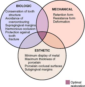
The principles of tooth preparation may be divided into three broad categories:
Successful tooth preparation and subsequent restoration depend on simultaneous consideration of all these factors. Improvement in one area often adversely affects another area, and striving for perfection in one may lead to failure in another. For example, in the fabrication of a metal-ceramic crown (see Chapter 24), sufficient thickness of porcelain is necessary for a lifelike appearance. However, if too much tooth structure is removed to accommodate a greater thickness of porcelain for esthetic reasons, the pulpal tissue may be traumatized (biologic consideration) and the tooth unduly weakened (mechanical consideration). In-depth knowledge and an understanding of the various criteria are prerequisite to the development of satisfactory tooth preparation skills. Predictable accomplishment of optimum tooth preparation (Fig. 7-1) often includes finding the best combination of compromises among the applicable biologic, mechanical, and esthetic considerations.
BIOLOGIC CONSIDERATIONS
Surgical procedures involving living tissues must be carefully executed to avoid unnecessary damage. The adjacent teeth, soft tissues, and the pulp of the tooth being prepared are easily damaged in tooth preparation. If poor preparation leads to inadequate marginal fit or deficient crown contour, plaque control around fixed restorations becomes more difficult. This impedes the long-term maintenance of dental health.
Prevention of Damage during Tooth Preparation
Adjacent teeth
Iatrogenic damage to an adjacent tooth is a common error in dentistry. Even if a damaged proximal contact area is carefully reshaped and polished, it is more susceptible to dental caries than was the original undamaged tooth surface. This is presumably because the original surface enamel contains higher fluoride concentrations and the interrupted layer is more prone to plaque retention.1 The technique of tooth preparation must avoid and prevent damage to the adjacent tooth surfaces.
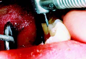
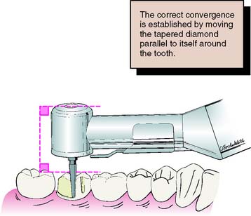
A metal matrix band around the adjacent tooth for protection may be helpful; however, the thin band can nonetheless be perforated and the underlying enamel damaged. The preferred method is to use the proximal enamel of the tooth that is being prepared for protection of the adjacent structures. Teeth are 1.5 to 2 mm wider at the contact area than at the cementoenamel junction. Therefore, a thin, tapered diamond can be passed through the interproximal contact area (Fig. 7-2) to leave a slight lip or fin of enamel without resulting in excessive tooth reduction or necessitating undesirable angulation of the rotary instrument. The latter situation, tipping the diamond unnecessarily away from the adjacent proximal surface, is a common clinical error.
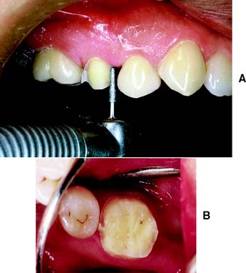
Fig. 7-2 Damage to adjacent teeth is prevented by positioning the diamond so a thin lip of enamel is retained between the bur and the adjacent tooth. A, Note that the orientation of the diamond parallels the long axis of this premolar. B, Proximal reduction almost complete. Note that enamel was maintained mesial to the path of the diamond as the reduction progressed.
Soft tissues
Damage to the soft tissues of the tongue and cheeks can be prevented by careful retraction with an aspirator tip, mouth mirror (Fig. 7-3), or flanged saliva ejector. Great care is needed to protect the tongue when the lingual surfaces of mandibular molars are being prepared.
Pulp
Great care also is needed to prevent pulpal injuries during fixed prosthodontic procedures, especially complete crown preparation. Pulpal degeneration that occurs many years after tooth preparation has been documented.2 Extreme temperatures, chemical irritation, or microorganisms can cause an irreversible pulpitis,3 particularly when they occur on freshly sectioned dentinal tubules. Prevention of pulpal damage necessitates selection of techniques and materials that reduce the risk of damage while tooth structure is prepared.4
Tooth preparations must account for the structure of the dental pulp chamber. Pulp size, which can be evaluated on a radiograph, decreases with age. Up to about age 50, it decreases more so occlusocervically than faciolingually. Average pulp dimensions have been related to coronal contour5 and are presented in Table 7-1 and Figure 7-4.
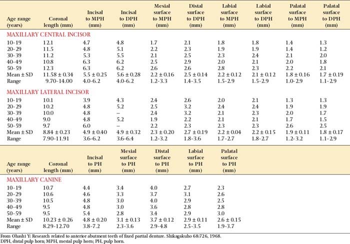
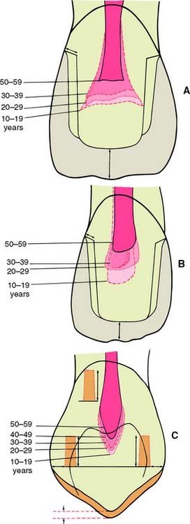
Fig. 7-4 Relationship between tooth preparation and pulp chamber size. The dotted lines represent pulp chamber structure at various ages. A, Maxillary central incisor with a metal-ceramic crown preparation. B, Maxillary lateral incisor with a metal-ceramic crown preparation. C, Maxillary canine with a pinledge preparation.
(From Ohashi Y: Research related to anterior abutment teeth of fixed partial denture. Shikagakuho 68:726, 1968.)
Causes of injury
Temperature
Considerable heat is generated by friction between a rotary instrument and the surface being prepared (Fig. 7-5). Excessive pressure, higher rotational speeds, and the type, shape, and condition of the cutting instrument (Fig. 7-6) may all increase generated heat.6 With a high-speed handpiece, a feather-light touch allows efficient removal of tooth material with minimal heat generation. Nevertheless, even with the lightest touch, the tooth overheats unless a water spray is used. This must be accurately directed at the area of contact between tooth and bur. The spray also removes debris—which is important because clogging reduces cutting efficiency (Fig. 7-7)—and prevents desiccation of the dentin (a cause of severe pulpal irritation).2,7 Debris accumulation has been shown to vary with rotary instrument shape. Shoulder- and chamfer-shaped diamonds may accumulate less debris. Debris is not readily removed after 5 minutes of ultrasonic cleaning.8
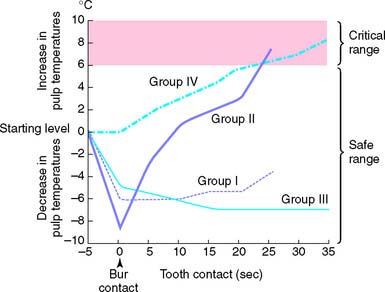
Fig. 7-5 Pulpal temperature rise during tooth preparation. Group I, air turbine, water cooled. Group II, air turbine, dry. Group III, low speed, water cooled. Group IV, low speed, dry.
(From Zach L, Cohen G: Pulp response to externally applied heat. Oral Surg Oral Med Oral Pathol 19:515, 1965.)
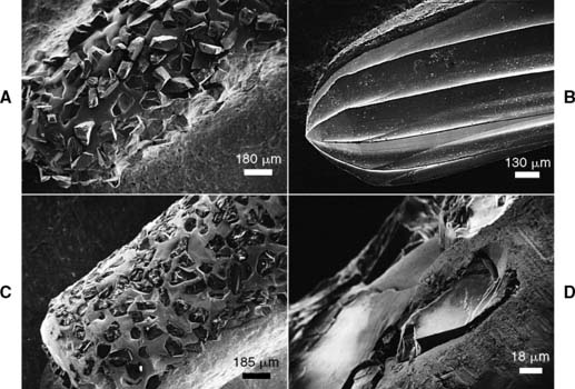
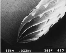
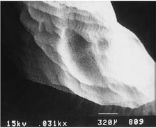
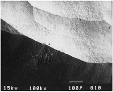
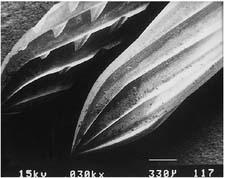
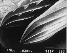
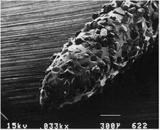
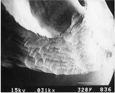
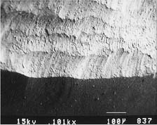
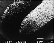
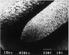
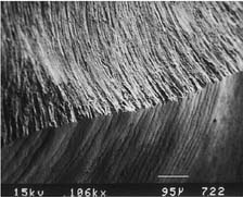
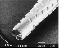
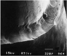
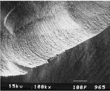
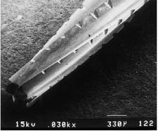
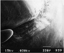
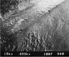
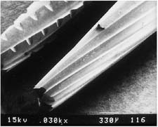
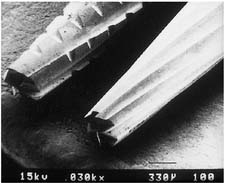
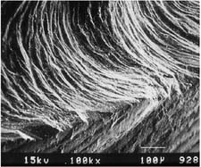
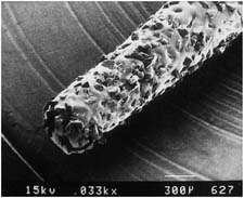
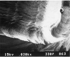
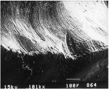
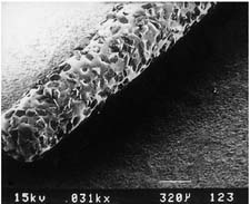
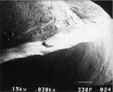
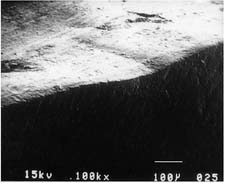
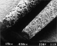
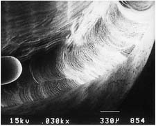
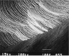
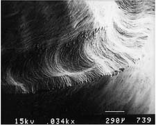
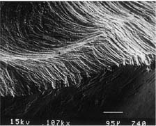
Fig. 7-6 Scanning electron micrographs of a rotary instrument. A, Unused diamond. B, Unused carbide. C, Worn diamond. D, Diamond particles have fractured at the level of the binder.
(Courtesy of Dr. J. L. Sandrik.)
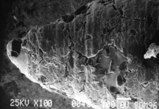
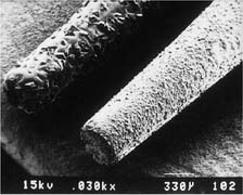
Fig. 7-7 Clogging on the tapered tip of a cylindrical diamond after one molar tooth preparation reduces cutting efficiency.
If the spray prevents adequate visibility, as may be the case when a lingual margin is being finished, a slow-speed handpiece or hand instrumentation should be used. Relying on air cooling with a high-speed handpiece is hazardous, because it can easily overheat a tooth and damage the pulp.9
Particular care is needed for preparing grooves or pinholes, because coolant cannot reach the cutting edge of the bur. To prevent heat buildup, these retention features should be prepared at low rotational speed.
Chemical action
The chemical action of certain dental materials (bases, restorative resins, solvents, and luting agents) can cause pulpal damage,10 particularly when they are applied to freshly cut dentin. Cavity varnish or dentin bonding agents form an effective barrier in most instances, but their effect on the retention of a cemented restoration is controversial.11-13
Chemical agents are sometimes used for cleaning and degreasing tooth preparations. However, they have been shown14 to be pulpal irritants. Thus, their use is generally contraindicated, particularly because they do not improve the retention of cemented restorations.15
Bacterial action
Pulpal damage under restorations has been attributed16,17 to bacteria that either were left behind or gained access to the dentin because of microleakage. However, many dental materials, including zinc phosphate cement, have an antibacterial effect.18 Because vital dentin seems to resist infection,19 the routine use of antimicrobial agents may not be advantageous. Many dentists now use an antimicrobial agent, such as chlorhexidine gluconate disinfecting solution (Consepsis*), after tooth preparation and before cementation, although the benefit has not been documented in clinical trials.20
Of importance is that all carious dentin should be removed before placement of a restoration that will serve as a foundation for a fixed prosthesis. An indirect pulp cap is not recommended on teeth that will subsequently receive cast restorations, because its later failure is likely to jeopardize extensive prosthodontic treatment.
Conservation of Tooth Structure
One of the basic tenets of restorative dentistry is to conserve as much tooth structure as possible while preparation design remains consistent with the mechanical and esthetic principles of tooth preparation. Tissue preservation reduces the harmful pulpal effects of the various procedures and materials used. The thickness of remaining dentin has been shown21 to be inversely proportional to the pulpal response, and tooth preparations extending in close proximity to the pulp should be avoided. Dowden22 argued that any damage to the odontoblastic processes would adversely affect the cell nucleus at the dentin-pulp interface, no matter how far from the nucleus it occurred. For this reason, in the assessment of likely adverse pulpal response, the amount of removed dentin is important; particular care must be exercised when vital teeth are prepared for complete-coverage restorations (Fig. 7-8).
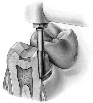
Fig. 7-8 A considerable amount of care is needed when a tooth is prepared for a complete crown, because of the extensive nature of the reduction, with many dentinal tubules sectioned. Each tubule communicates directly with the dental pulp.
Tooth structure is conserved through adherence to the following guidelines:
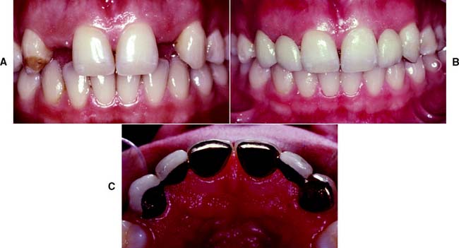
Fig. 7-9 Conservation of tooth structure by using partial-coverage restorations. In this case, they are used as fixed dental prosthetic abutments to replace congenitally missing lateral incisors.
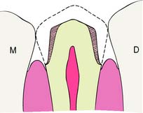
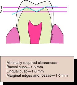
Fig. 7-11 An anatomically prepared occlusal surface results in adequate clearance without excessive tooth reduction. A flat occlusal preparation will result in either insufficient clearance (1) or an excessive amount of reduction (2).
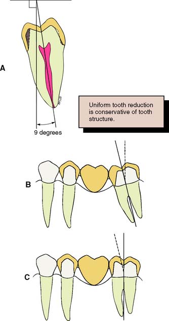
Fig. 7-12 To conserve tooth structure, the preparation of axial walls should be as uniform as possible. A, The path of placement should coincide with the long axis of the tooth, which for a mandibular molar is typically inclined 9 to 14 degrees lingually. Preparing such a tooth with a path of placement that is perpendicular to the occlusal plane of the mandibular arch is a commonly observed clinical error that results in additional unnecessary removal of tooth structure (shaded area). Malaligned teeth, such as a mesially tipped molar (B), necessitate additional removal of tissue on the mesial aspect of the molar abutment to achieve compatible paths of placement for a planned fixed dental prosthesis. C, If the molar abutment is orthodontically uprighted before tooth preparation, a more conservative crown preparation can be achieved.
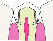
Fig. 7-13 A shoulder margin (2) is indicated when esthetic restorations are planned to achieve sufficient material thickness to achieve a lifelike appearance, but it is much less conservative than a chamfer (1).
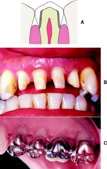
Fig. 7-14 A, Apical extension of the preparation can necessitate additional tooth reduction because coronal diameter becomes smaller. B, Preparations for periodontally involved teeth may necessitate considerable reduction if the margins are to be placed subgingivally for esthetic reasons. C, Supragingival margins are preferred where applicable.
Considerations Affecting Future Dental Health
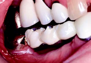
Improper preparation of a tooth may have an adverse effect on long-term dental health. For example, insufficient axial reduction inevitably results in overcontoured restorations that hamper plaque control. This may cause periodontal disease23 or dental caries. Alternatively, inadequate occlusal reduction may result in poor form and subsequent occlusal dysfunction. Poor choice of margin location, such as in the area of occlusal contact, may cause chipping of enamel or cusp fracture.
Axial reduction
Gingival inflammation is commonly associated with crowns and fixed dental prosthetic abutments that have excessive axial contours, probably because it is more difficult for the patient to maintain plaque control around the gingival margin24 (Fig. 7-15). A tooth preparation must provide sufficient space for the development of good axial contours. This enables the junction between the restoration and the tooth to be smooth and free of any ledges or abrupt changes in direction.
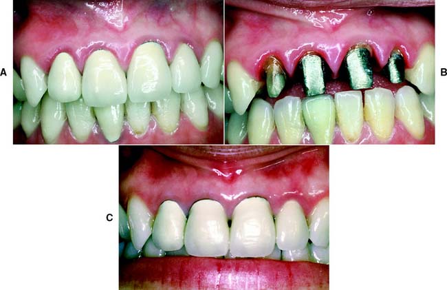
Fig. 7-15 A, Unhealthy gingival tissue resulting from overcontoured restorations. B, The tooth preparations are underreduced; C, Once the restorations are recontoured, gingival health returns.
Under most circumstances, a crown should duplicate the contours and profile of the original tooth (unless the restoration is needed to correct a malformed or malpositioned tooth). If an error is made, a slightly undercontoured flat restoration is better because it is easier to keep free of plaque; however, increasing proximal contour on anterior crowns to maintain the interproximal papilla25 (see Chapter 5) may be beneficial. Sufficient tooth structure must be removed to allow the development of correctly formed axial contours (Fig. 7-16), particularly in the interproximal and furcation areas of posterior teeth, where periodontal disease often progresses with serious consequences.
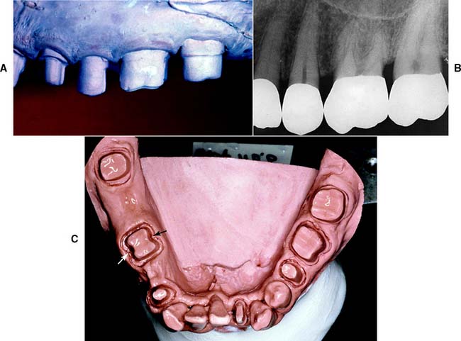
Fig. 7-16 A and B, Tooth preparations with adequate axial reduction allow the development of properly contoured embrasures. Tissue is conserved through the use of partial coverage and supragingival margins where possible. C, Preparing furcation areas adequately is important (arrows); otherwise, the restoration is excessively contoured, making plaque control difficult.
Margin placement
Whenever possible, the margin of the preparation should be supragingival. Subgingival margins of cemented restorations have been identified26-31 as a major etiologic factor in periodontal disease, particularly where they encroach on the epithelial attachment (see Chapter 5). Supragingival margins are easier to prepare accurately without trauma to the soft tissues. They can usually also be situated on hard enamel, whereas subgingival margins are often on dentin or cementum.
Other advantages of supragingival margins include the following:
A subgingival margin (Fig. 7-17), however, is justified if any of the following pertain:
Margin adaptation
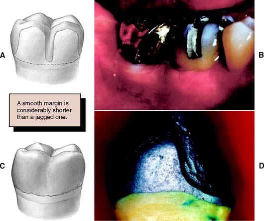
The junction between a cemented restoration and the tooth is always a potential site for recurrent caries because of dissolution of the luting agent and inherent roughness. The more accurately the restoration is adapted to the tooth, the lesser is the chance of recurrent caries or periodontal disease.32 Although a precise calculation for acceptable margin adaptation is not available, a skilled technician can routinely make castings that fit to within 10 μm33 and a porcelain margin that fits to within 50 μm,34 provided the tooth is properly prepared. A well-designed preparation has a smooth and even margin. Rough, irregular, or “stepped” junctions greatly increase overall margin length and substantially reduce the adaptation accuracy of the restoration (Fig. 7-18). The clinical significance of preparing smooth margins cannot be overemphasized. Time spent obtaining a smooth margin makes the subsequent steps of tissue displacement, impression making, die formation, waxing, and finishing much easier and ultimately results in a longer-lasting restoration.
Margin geometry
The cross-sectional configuration of the margin has been the subject of much analysis and debate.35-42 Different shapes have been described and advocated.43,44 For evaluation, the following guidelines for margin design should be considered:
Proposed margin designs are presented in Table 7-2.
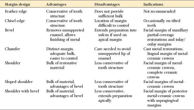
Although they are conservative of tooth structure, feather edge or shoulderless crown preparations (Fig. 7-19A) should be avoided because they do not provide adequate bulk at the margins. Overcontoured restorations often result from feather edge margins because the technician can handle the wax pattern without distortion only by increasing its bulk beyond the original contours. A variation of the feather edge, the chisel edge margin (Fig. 7-19B), is formed when there is a larger angle between the axial surfaces and the unprepared tooth structure. Unfortunately, this margin is frequently associated with preparations with excessive angles of convergence (taper) and preparations in which the orientation of the axial reduction is not correctly aligned with the long axis of the tooth.
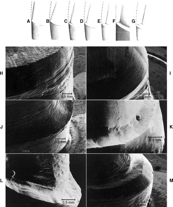
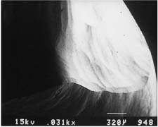
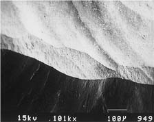
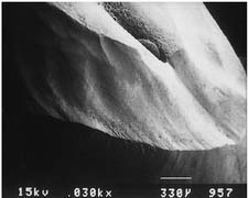
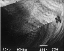
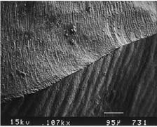
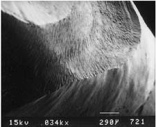
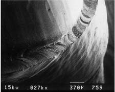
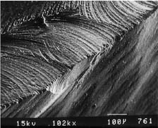
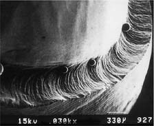
Fig. 7-19 Margin designs. A, Feather edge. B, Chisel. C, Chamfer. D, Bevel. E, Shoulder. F, Sloped shoulder. G, Beveled shoulder. H to M, Scanning electron micrographs. H, Feather-chisel edge. I, Bevel. J, Chamfer. K, Shoulder. L, Sloped shoulder. M, Beveled shoulder.
(Courtesy of Dr. H. Lin.)
Under most circumstances, feather edges and chisel edges are unacceptable. Historically, their main advantage was that they facilitated impression making with rigid modeling compound in copper bands (a technique rarely used today). They were useful for that purpose, because there was no ledge on which a band could catch. A chamfer margin (Fig. 7-19C) is particularly suitable for cast metal crowns and the metal-only portion of metal-ceramic crowns (Fig. 7-20). It is distinct and easily identified, and it provides room for adequate bulk of material and development of anatomically correct axial contours. Chamfers can be placed expediently and with precision, although care is needed to avoid leaving a ledge of unsupported enamel.
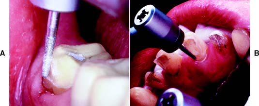
Fig. 7-20 Chamfer margins are recommended for cast metal crowns (A) and the lingual margin of a metal-ceramic crown (B).
Probably the most suitable instrument for making a chamfer margin is the tapered diamond with a rounded tip; the resulting margin is the exact image of the instrument (Fig. 7-21). Marginal accuracy depends on having a high-quality diamond and a true-running handpiece. The gingival margin is prepared with the diamond held precisely in the intended path of placement of the restoration (Fig. 7-22).
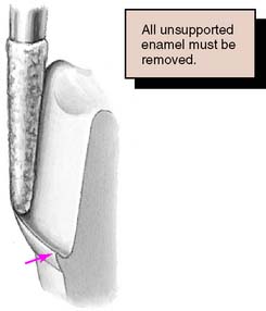
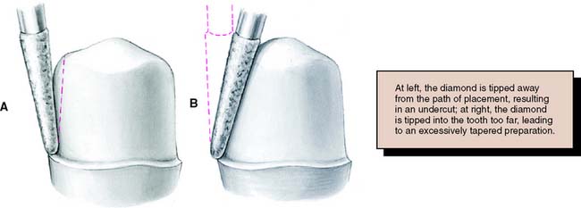
Fig. 7-22 Precise control of the orientation of the diamond is very important. A, Tilting away from the tooth creates an undercut: Opposing axial preparation walls diverge in an occlusal direction. B, Tilting toward the tooth results in an excessive convergence angle of the preparation.
Tilting it away from the tooth will create an undercut, whereas angling it toward the tooth will lead to overreduction and loss of retention. The chamfer should never be prepared wider than half the tip of the diamond; otherwise, an unsupported lip of enamel may result (Fig. 7-23). Some authorities have recommended the use of a diamond with a noncutting guide tip to aid accurate chamfer placement.45 However, such guides have been shown to damage tooth structure beyond the intended preparation margin.46
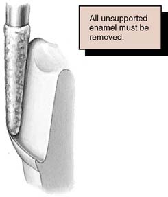
Fig. 7-23 A chamfer should not be wider than half the bur used to form it. Otherwise, a lip of unsupported enamel will be left.
Under some circumstances a beveled margin (see Fig. 7-19D) is more suitable for cast restorations, particularly if a ledge or shoulder already exists, possibly as a result of dental caries, cervical erosion, or a previous restoration. The objective in beveling is threefold: (1) to allow the cast metal margin to be bent or burnished against the prepared tooth structure; (2) to minimize the marginal discrepancy35 caused by a complete crown that fails to seat completely (however, Pascoe40 showed that when an oversized crown is considered, the discrepancy is increased rather than decreased [Fig. 7-24]); and (3) to protect the unprepared tooth structure from chipping (e.g., by removing unsupported enamel). NOTE: when access for burnishing is limited, there is little advantage in beveling. This applies particularly to a gingival margin, where beveling would lead to subgingival extension of the preparation or placement of the margin on dentin rather than on enamel. Facial margins of maxillary partial-coverage restorations should be beveled to eliminate all unsupported enamel, to protect the remaining tooth structure from fracture, and to allow for burnishing of the casting.
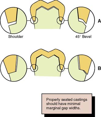
Fig. 7-24 Effect on marginal fit of beveling the gingival margin. A, If the internal cross-section of a crown is the same as or less than that of the prepared tooth, a 45-degree bevel decreases the marginal discrepancy by 70%. B, If the internal diameter is slightly larger than the prepared tooth, beveling increases the marginal discrepancy. In practice, crowns are made slightly larger than the prepared tooth to allow for the luting agent.
Because a shoulder margin (Fig. 7-19E) allows room for porcelain, it is recommended for the facial part of metal-ceramic crowns, especially when the porcelain margin technique is used. It should form a 90-degree angle with the unprepared tooth surface. An acute angle is likely to chip (Fig. 7-25A). In practice, dentists tend to underprepare the facial shoulder,47 which leads to restorations with inferior esthetics or poor axial contour.
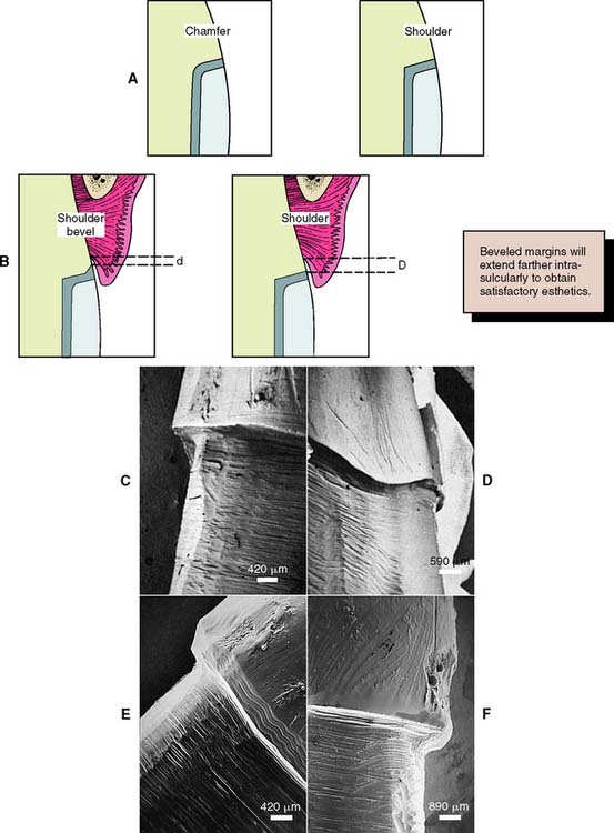
Fig. 7-25 A, A shoulder provides more bulk of metal than a heavy chamfer, which may facilitate the laboratory steps. B, A disadvantage of the shoulder bevel is that its margin must be placed deeper in the gingival sulcus so that the wider band of metal will be hidden (compare d with D). C, Scanning electron micrograph of a shoulder margin prepared with a high-speed diamond. D, This margin has been refined with a sharp chisel. E, This has been beveled with a tungsten carbide bur. F, This bevel was placed with a sharp hand instrument.
(Microscopy by Dr. J. Sandrik; teeth prepared by Dr. G. Byrne.)
Some authorities48 have recommended a heavy chamfer rather than a shoulder margin, and some find a chamfer easier to prepare with precision. Earlier workers38,39 found less distortion of the metal framework during porcelain application with a shoulder margin, although with modern alloys, these results could not be replicated.49-52
A 120-degree sloped shoulder margin (Fig. 7-19F) is sometimes used as an alternative to the 90-degree shoulder for the facial margin of metal-ceramic crowns. The sloped shoulder reduces the possibility of leaving unsupported enamel but leaves sufficient bulk to allow thinning of the metal framework to a knife-edge for acceptable esthetics.
A beveled shoulder margin (Fig. 7-19G) is recommended by some authorities for the facial surface of a metal-ceramic restoration in which a metal collar (as opposed to a porcelain labial margin) is used. The beveling removes unsupported enamel and may allow some finishing of the metal. However, a shoulder or sloped shoulder is preferred for biologic and esthetic reasons. This allows improved esthetics because the metal margin can be thinned to a knife edge and hidden in the sulcus without the need for positioning the margin closer to the epithelial attachment (Fig. 7-25B). Table 7-3 illustrates chamfer and shoulder preparations obtained with selected instruments.
Table 7-3 MARGINS PRODUCED BY VARIOUS TYPES OF BURS
| Bur appearance | Low magnification of the prepared margin | High magnification of the prepared margin |
|---|---|---|
| CHAMFERS | ||
| Chamfer carbide (high speed) | ||
 |
 |
 |
| Chamfer carbide (high speed) | ||
| Finishing carbide (high speed) | ||
 |
 |
 |
| Chamfer carbide (high speed) | ||
| Finishing carbide (low speed) | ||
 |
 |
 |
| Chamfer diamond coarse (high speed) | ||
 |
 |
 |
| Chamfer diamond coarse (high speed) | ||
| Fine diamond (high speed) | ||
 |
 |
 |
| Chamfer diamond coarse (high speed) | ||
| Chamfer diamond fine (low speed) | ||
 |
 |
 |
| SHOULDERS | ||
| Cross-cut fissure (high speed) | ||
 |
 |
 |
| Cross-cut fissure (high speed) and hoe | ||
 |
 |
 |
| Cross-cut fissure carbide (high speed) | ||
| Finishing carbide (high speed) | ||
 |
 |
 |
| Cross-cut fissure carbide (high speed) | ||
| Finishing carbide (low speed) | ||
 |
 |
 |
| Flat-end coarse diamond (high speed) | ||
 |
 |
 |
| Flat-end coarse diamond (high speed) and hoe | ||
 |
 |
 |
| Flat-end coarse diamond (high speed) | ||
| Fine grit diamond (high speed) | ||
 |
 |
 |
| Flat-end coarse diamond (high speed) | ||
| Fine grit diamond (low speed) | ||
 |
 |
 |
Courtesy of Dr. H. Lin.
A comprehensive 2001 literature review of current scientific knowledge on complete coverage tooth preparations suggests that margin design selection should be based on the type of crown, applicable esthetic requirements, ease of formation, and operator experience. Research has not validated the expectation of enhanced fit being associated with selection of certain types of finish line geometry.53
Occlusal considerations
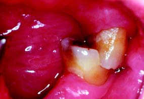
A satisfactory tooth preparation allows sufficient space for developing a functional occlusal scheme in the finished restoration. Sometimes the patient’s occlusion is disrupted by supraerupted or tilted teeth (Fig. 7-26). When these teeth are prepared for restoration, the eventual occlusal plane must be carefully analyzed and the teeth reduced accordingly. Considerable reduction is often needed to compensate for the supraeruption of abutment teeth. In turn, this may shorten tooth preparation axial wall height, with associated mechanical consequences such as reduced retention and resistance (see p. 226).
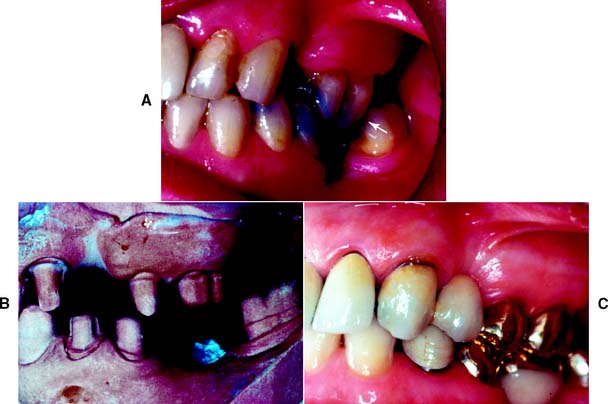
Fig. 7-26 A, Nonreplacement of missing teeth has led to supraocclusion and a protrusive interference (arrow). B, Teeth reduced with the help of trial tooth preparations and diagnostic waxing. C, Restorations with anterior guidance.
Sometimes even endodontic treatment is necessary to make enough room. However, under these circumstances, compromising the principle of conservation of tooth structure is preferable to the potential harm from a traumatic occlusal scheme. Careful judgment is obviously needed. Diagnostic tooth preparations and waxing procedures are essential to help determine the exact amount of reduction necessary to develop an optimum occlusion.
Preventing tooth fracture
No tooth is unbreakable. If teeth are smashed together (as in an automobile accident, sport injury, or biting unexpectedly on a hard object), a cusp may break. Cuspal fracture also can occur from parafunctional habits such as bruxism.
The likelihood that a restored tooth will fracture can be lessened if the tooth preparation is designed to minimize potentially destructive stresses (Fig. 7-27). For example, an intracoronal cast restoration (inlay) has a greater potential for fracture because when occlusal forces are applied to the restoration, it tends to wedge opposing walls of the tooth apart. This wedging must be resisted by the remaining tooth structure; if the remaining tooth structure is thin (as with a wide preparation isthmus), the tooth may fracture during function. Providing a cuspal coverage restoration (onlay) rather than an inlay lessens the chance of such fracture.54 However, although not as conservative of tooth structure, a complete crown is often a better solution, because it offers the greatest protection against tooth fracture, tending to “hold” the cusps of the tooth together.
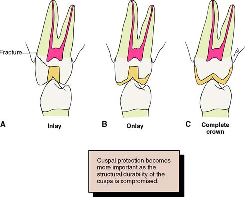
Fig. 7-27 A, An intracoronal cast restoration (inlay) can act as a wedge during cementation or function. If the cusps are weakened, fracture will occur. B, A cuspal-coverage onlay provides better protection but often lacks retention. C, A complete crown provides the best protection against fracture. It also has the best retention, but it can be associated with periodontal disease and poor esthetics.
(Redrawn from Rosenstiel SF: Fixed bridgework—the basic principles. In Rayne J, ed: General Dental Treatment, London, Kluwer Publishing, 1983.)
MECHANICAL CONSIDERATIONS
The design of tooth preparations for fixed prosthodontics must adhere to certain mechanical principles; otherwise, the restoration may become dislodged or may distort or fracture during service. These principles have evolved from theoretical and clinical observations and are supported by experimental studies.
Mechanical considerations can be divided into three categories:
Retention Form
Certain forces (e.g., when the jaws are moved apart after biting on very sticky food) act on a cemented restoration in the same direction as the path of placement. The quality of a preparation that prevents the restoration from becoming dislodged by such forces parallel to the path of placement is known as retention. Only dental caries and porcelain failure outrank lack of retention as a cause of failure of crowns and fixed dental prostheses.55,56
The following factors must be considered when the dentist decides whether retention is adequate for a given fixed restoration:
Magnitude of the dislodging forces
Forces that tend to remove a cemented restoration along its path of placement are small in comparison with those that tend to seat or tilt it. A fixed dental prosthesis or splint can be subjected to such forces by pulling with floss under the connectors; however, the greatest removal forces generally arise when exceptionally sticky food (e.g., caramel) is eaten. The magnitude of the dislodging forces exerted by the elevator muscles depends on the stickiness of the food and the surface area and surface texture of the restoration.
Geometry of the tooth preparation
Most fixed dental prostheses depend on the geometric form of the preparation rather than on adhesion for retention because most of the traditional cements (e.g., zinc phosphate) are nonadhesive (i.e., they act by increasing the frictional resistance between tooth and restoration). The grains of cement prevent two surfaces from sliding, although they do not prevent one surface from being lifted from another. This is analogous to the effect of particles of sand or dust within machinery. They do not have a specific adhesion to metal, but they increase the friction between sliding metal parts. If sand or dust gets into an old-fashioned mechanical camera or watch, the increase in friction can effectively jam the mechanism.
Cement is effective only if the restoration has a single path of placement (i.e., the tooth is shaped to restrain the free movement of the restoration). The relationship between a nut and a bolt is an example of restrained movement (Fig. 7-28). The nut is not free to move in any direction but can move only along the precisely determined helical path of the threads on the bolt.
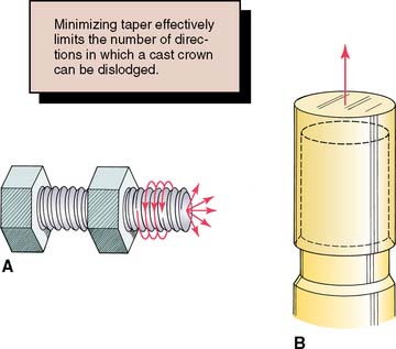
Fig. 7-28 A, The relationship of a nut and a bolt is an example of restrained movement; the nut must move along a precisely defined helical path (arrows). B, For effective retention, a tooth preparation must constrain the movement of a restoration. For this to occur, it must be cylindrical. (See Fig. 7-29.)
The relationship between two bodies, one (in this case a tooth preparation) restraining movement of the other (a cemented restoration), has been studied mathematically and is known in analytical mechanics as a closed lower pair of kinematic elements.57 In fixed prosthodontics, a sliding pair is the only pair that has relevance. It is formed by two cylindrical* surfaces constrained to slide along one another. The elements are constrained if the curve that defines the cylinder is closed or shaped to prevent movement at right angles to the axis of the cylinder (Fig. 7-29).
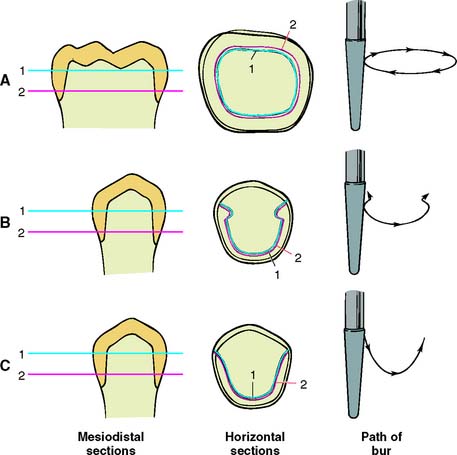
Fig. 7-29 A preparation is cylindrical if the two horizontal cross-sections of the prepared axial tooth surface (1 and 2) are coincident. A, This complete crown is cylindrical and therefore retentive. B, A partial crown is retentive if its sections are coincident and perpendicular movement is prevented by grooves. C, This preparation is cylindrical (1 and 2 coincide) but not retentive, because it can move perpendicularly to the axis of the cylinder.
(Redrawn from Rosenstiel E: The retention of inlays and crowns as a function of geometrical form. Br Dent J 103:388, 1957.)
A tooth preparation is cylindrical if the axial surfaces are prepared by a cylindrical bur held at a constant angle. The gingival margin of the preparation becomes the fixed curve of the mathematical definition, and the occlusoaxial line angle of the tooth preparation should be a replica of the gingival margin geometry. The curve of a complete crown preparation is closed, whereas the grooves of a partial crown preparation prevent movement at right angles to the long axis of the cylinder. However, if one wall of the complete crown preparation is overtapered, it is no longer cylindrical, and the cemented restoration is not constrained by the preparation because the restoration then has multiple paths of withdrawal. Under these circumstances, the cement particles tend to lift away from rather than slide along the preparation, and the only retention is a result of the cement’s limited adhesion (Fig. 7-30).
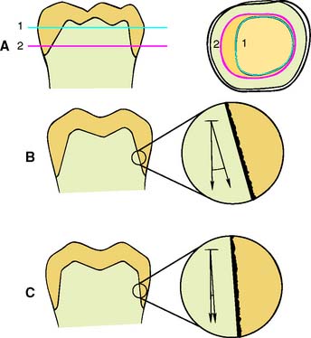
Fig. 7-30 A, Cross sections 1 and 2 do not coincide, and the preparation thus has little retention. B, Under these circumstances, very little friction develops between the cement and the axial walls, and the cement is subjected to tensile stress. C, A retentive near-parallel preparation with frictional resistance. The cement is placed under shear stress.
(A, Redrawn from Rosenstiel E: The retention of inlays and crowns as a function of geometrical form. Br Dent J 103:388, 1957.)
Taper
Taper is defined as the convergence of two opposing external walls of a tooth preparation as viewed in a given plane. The extension of those planes form an angle described as the angle of convergence. Theoretically, maximum retention is obtained if a tooth preparation has parallel walls. However, it is neither desirable nor practical to prepare a tooth this way with current techniques and instrumentation, because slight undercuts that prevent the restoration from seating are then created.
An undercut on a complete crown preparation is defined as any irregularity in the wall of a prepared tooth that prevents the withdrawal or seating of a wax pattern or casting. Such is the case when divergence is inadvertently created between opposing axial walls, or wall segments, in a cervical-occlusal direction (Fig. 7-31A). In other words, if the cervical diameter of a tooth preparation at the margin is narrower than at the occlusoaxial junction (reverse taper), it is impossible to seat a complete cast crown of similar geometry (see Fig. 7-31B). Undercuts can be present whenever two axial walls face in opposite directions (see Fig. 7-31C). Thus, the mesial wall of a complete cast crown preparation can be undercut in relation to the distal wall; in addition, the buccal wall can be undercut in relation to the lingual wall, and the mesiobuccal wall can be undercut in relation to the distolingual wall; in a partial veneer preparation, in accordance with the same principle, the lingual wall of a proximal groove can be undercut in relation to the lingual wall of the preparation, but the buccal wall of the same groove cannot be undercut in relation to the lingual preparation wall; either of these walls may restrict the number of directions in which a casting can be placed on the preparation in relation to the other, however.
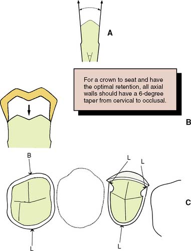
Fig. 7-31 A, An undercut is formed if opposing walls diverge. B, A tooth prepared with an undercut does not permit the crown to seat, inasmuch as it cannot pass over the divergent walls. C, Undercuts are possible in other locations when fixed dental prostheses or restorations with preparation features such as grooves or boxes are prepared. Here one buccally facing wall (B) can be undercut relative to (four) lingual facing walls (L).
A slight convergence, or taper, is clinically desirable in complete crown preparations. As long as this taper is small, the movement of the cemented restoration will be effectively restrained by the preparation and will have what is known as a limited path of placement. As taper increases, however, so does the free movement of the restoration, and consequently, retention will be reduced.
The relationship between the degree of axial wall taper and the magnitude of retention was first demonstrated experimentally by Jørgensen58 in 1955. He cemented brass caps on Galalith cones of different tapers and measured retention with a tensile-testing machine. The relationship was found to be hyperbolic, with retention rapidly becoming less as taper increased (Fig. 7-32), although the relationship was no longer hyperbolic when the internal surfaces of the caps were roughened. The retention of a cap with 10 degrees of taper* was approximately half that of a cap with 5 degrees. Similar results have been reported by other workers.59-61
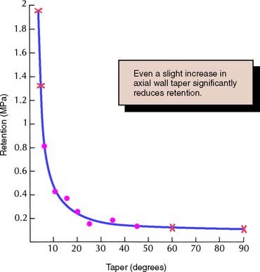
Fig. 7-32 Relationship between retention and convergence angle. •, Experimental values; x, calculated values outside the experimental range.
(Redrawn from Jørgensen KD: The relationship between retention and convergence angle in cemented veneer crowns. Acta Odontol Scand 13:35, 1955.)
Selection of the appropriate degree of taper for tooth preparation involves compromise. Too small a taper may lead to unwanted undercuts; too large leads to a lack of retention. The recommended convergence between opposing walls is 6 degrees, which has been shown to optimize retention for zinc phosphate cement.62 Being able to recognize this angle is important (Fig. 7-33). It is necessary to be able to rapidly quantify the approximate angle of convergence between preparation walls. It is not necessary to deliberately tilt a rotary cutting instrument to create a taper, because this invariably leads to overpreparation. Rather, teeth are readily prepared with a rotary instrument of the desired taper held at a constant angulation. The rotary instrument is moved through a cylindrical path as the tooth is prepared, and the taper of the instrument should produce the desired axial wall taper on the completed preparation. In practice, many dentists experience difficulty consistently avoiding excessively tapered preparations, particularly when preparing posterior teeth with limited access.63-65

Fig. 7-33 The recommended convergence angle is 6 degrees. This is a very slight taper. (The angle between the hands of a clock showing 12:01 is 5½ degrees.)
Clinicians have a tendency to overtaper preparations in a buccolingual direction more so than mesiodistally, and abutments for fixed dental prostheses tend to be prepared with greater taper than do single crown preparations.66
Some authorities recommend the routine use of grooves to reduce the incidence of restoration displacement. It is unclear, however, whether accurate groove alignment is achieved more easily than axial wall convergence. Skillfully prepared axial walls at a minimal convergence are very conservative of tooth structure.
Surface area
If the restoration has a limited path of placement, its retention depends on the length of this path or, more precisely, on the surface area that is in sliding contact. Therefore, crowns with tall axial walls are more retentive than those with short axial walls,67 and molar crowns are more retentive than premolar crowns of similar taper, because of the greater diameter of the molar. Surfaces on which the crown is essentially being pulled away from rather than sliding along the tooth, such as the occlusal surface, do not add significantly to total retention.
Stress concentration
When a retentive failure occurs, cement often adheres to both the tooth preparation and the fitting surface of the restoration. In these cases, cohesive failure occurs through the cement layer because the strength of the cement is less than the induced stresses. A computerized analysis of these stresses68,69 reveals that they are not uniform throughout the cement but are concentrated around the junction of the axial and occlusal surfaces. Sharp occlusoaxial line angles should be rounded to minimize these stresses, which can precipitate retentive failure.68,69 Changes in preparation geometry may thus indirectly increase the retention of the restoration.
Type of preparation
Different types of preparation have different retentive values that correspond fairly closely to the total surface area of the axial walls with restricted taper, as long as other factors (e.g., preparation height) are kept constant. Thus, the retention of a complete crown is more than double that of partial-coverage restorations70 (Fig. 7-34).
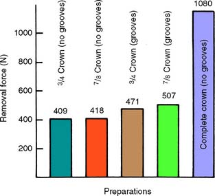
Fig. 7-34 Retention of different preparation designs.
(From Potts RG, et al: Retention and resistance of preparations for cast restorations. J Prosthet Dent 43:303, 1980.)
Adding grooves or boxes (Fig. 7-35) to a preparation with a limited path of placement does not markedly affect its retention, because the surface area is not increased significantly. However, where the addition of a groove limits the paths of placement, retention is increased.71,72
Roughness of the surfaces being cemented
When the internal surface of a restoration is very smooth, retentive failure occurs not through the cement but at the cement-restoration interface. Under these circumstances, retention is increased if the restoration is roughened or grooved.73-75 The casting is most effectively prepared by air-abrading the fitting surface with 50 μm of alumina. This should be done carefully to avoid abrading the polished surfaces or margins. Airborne particle abrasion has been shown76 to increase in vitro retention by 64%. Similarly, acid-etching of the fitting surface of restorations can improve retention with certain luting agents.
Failure rarely occurs at the cement-tooth interface. Therefore, deliberately roughening the tooth preparation hardly influences retention and is not recommended, because roughness adds to the difficulty of subsequent technical steps in crown fabrication such as impression making and waxing (see Chapters 14 and 18).
Materials being cemented
Retention is affected by both the type of casting alloy and any core or buildup material that is present on the axial walls of the crown preparation. The clinical significance of laboratory testing results have yet to be confirmed by longer term clinical studies, but it appears that the more reactive the alloy is, the more adhesion there is with selected luting agents. Therefore, base metal alloys are better retained than are less reactive metals with high gold content.77 The effect of adhesion to different core materials also has been tested, with conflicting results. In one laboratory study,78 researchers examining adhesion between cements and core materials found that the cement adhered better to amalgam than to composite resin or cast gold. However, when crowns were tested for retention, higher values were found with the composite resin than with amalgam cores.79 The differences may have resulted from dimensional changes of the core materials, although the clinical implications of this finding are not clear.
Type of luting agent
The type of luting agent chosen affects the retention of a cemented restoration.80-82 However, the decision regarding which agent to use is also based on other factors. In general, the data suggest that adhesive resin cements are the most retentive83,84 (Fig. 7-36), although long-term clinical evidence about the durability of the bond is not available. Of concern is that long-term in vitro studies have shown deterioration of the resin-dentin bond associated with permeability of the hybrid layer to small ions or molecules, so-called nanoleakage.85,86
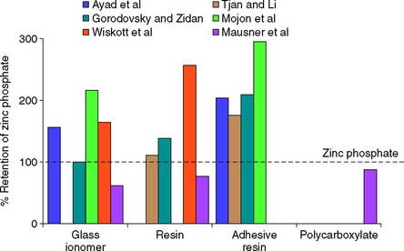
Fig. 7-36 Crown retention studies. Effect of luting agent. Six in vitro studies evaluated the effect of luting agent on crown retention.† The data were normalized as a percentage of the retention value with zinc phosphate cement. Adhesive resins had consistently greater retention than zinc phosphate. Conventional resins and glass ionomers yielded less consistent results.
(From Rosenstiel SF, et al: Dental luting agents: a review of the current literature. J Prosthet Dent 80:280, 1998.)
Film thickness of the luting agent
There is conflicting evidence87-90 about the effect of increased thickness of the cement film on retention of a restoration. This may be important if a slightly oversized casting is made (as when the die-spacer technique is used; see Chapter 18).
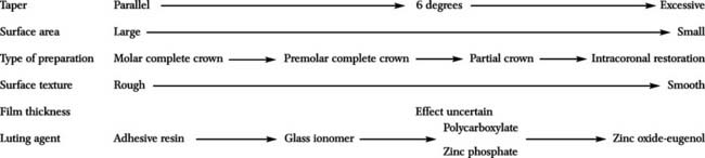
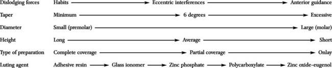
The factors that influence the retention of a cemented restoration are summarized in Table 7-4.
Table 7-4 FACTORS INFLUENCING THE RETENTION OF A CEMENTED RESTORATION
 |
Resistance Form
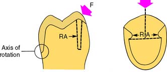
Certain features must be present in the preparation to prevent dislodgment of a cemented restoration. Mastication and parafunctional activity may subject a prosthesis to substantial horizontal or oblique forces. These forces are normally much greater than the ones overcome by retention, especially if the restoration is loaded during eccentric contact between posterior teeth. Lateral forces tend to displace the restoration by causing rotation around the gingival margin. Rotation is prevented by any areas of the tooth preparation that are placed in compression, called resistance areas (Fig. 7-37). Multiple resistance areas cumulatively make up the resistance form of a tooth preparation, which is defined as the features of a tooth preparation that enhance the stability of a restoration and resist dislodgment along an axis other than the path of placement.
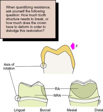
Fig. 7-37 The resistance area (RA) of a complete crown is placed under compression when a lateral force (F) is applied. NRA, Nonresisting area.
(Redrawn from Hegdahl T, Silness J: Preparation areas resisting displacement of artificial crowns. J Oral Rehabil 4:201, 1977.)
Adequate resistance depends on the following:
Magnitude and direction of the dislodging forces
Some patients can develop enormous biting forces. Gibbs and colleagues91 discovered one individual (Fig. 7-38) who had a biting force of 4340 N (443 kg).* Although this is considered extraordinary, restorations should nevertheless be designed to withstand forces approaching such magnitude. In one laboratory study,68 a complete crown cemented on a nickel-chromium test die was found to be capable of withstanding more than 13,500 N (1400 kg)—a far greater force than would occur in the mouth—before becoming displaced (Fig. 7-39).
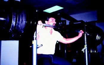
Fig. 7-38 Mr. H. sitting beside 443 kg of gymnasium weights to illustrate the magnitude of his biting strength.
(Reproduced from Gibbs CH, et al: Limits of human bite strength. J Prosthet Dent 56:226, 1986.)
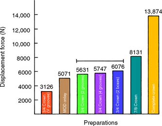
Fig. 7-39 Resistance of different preparation designs. The line connects preparations with statistically similar displacement forces (p > 0.05). MOD, mesio-occlusal-distal.
(Modified from Kishimoto M, et al: Influence of preparation features on retention and resistance. Part II: three-quarter crowns. J Prosthet Dent 49:188, 1983.)
In a normal occlusion, biting force is distributed over all the teeth; most of it is axially directed. If a fixed prosthesis is carefully made with a properly designed occlusion, the load should be well distributed and favorably directed (see Chapter 4). However, if a patient has a biting habit such as pipe smoking or bruxing, it may be difficult to prevent fairly large oblique forces from being applied to a restoration. Consequently, the completed tooth preparation and restoration must be able to withstand considerable oblique forces as well as the normal axial ones, and it has been argued that from a clinical durability perspective, adequate resistance form may be more crucial than overall preparation retentiveness.92,93
Geometry of the tooth preparation
As with retention, preparation geometry plays a key role in attaining desirable resistance form. The tooth preparation must be shaped so that particular areas of the axial wall prevent rotation of the crown. A good way to determine whether tooth preparation geometry provides adequate resistance form is to answer the question: “How much tooth structure needs to break off in order for this crown to be displaced by tipping off the tooth?”
Resistance is a function of the relationship between axial wall taper, preparation diameter, and preparation height. It decreases as taper or diameter increases, or preparation height is reduced.94
The relationship between preparation height, or diameter, and resistance to displacement is approximately linear.95
Preparation taper of 5 to 22 degrees has been suggested as being within a clinically acceptable range.96,97 However, at the higher end of this range, the tipping resistance of both cemented and uncemented cast restorations is inadequate but increases significantly as taper is reduced.96,98
Short tooth preparations with large diameters were found to have very little resistance form. In general, molar teeth require more parallel preparation than do premolar or anterior teeth to achieve adequate resistance form.99 A 3-mm preparation height provides adequate resistance if taper is restricted to 10 degrees or less,98 but additional height is necessary as tooth diameter increases. Thus, on molar crown preparations in which many more preparations are observed that lack resistance,100 minimal preparation wall height should ideally be in the range of 3.5 to 4 mm.
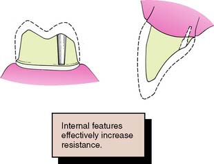
Hegdahl and Silness100 analyzed how the areas that provide resistance form change as modifications are made in the geometry of the tooth preparation. They demonstrated that increasing preparation taper and rounding of axial angles tend to reduce resistance, pyramidal preparations thus having greater resistance than conical ones. Proximal grooves or boxes placed in healthy tooth structure are particularly effective in enhancing the resistance form of crown preparations because these interfere with rotational movement (tipping) of the crown and in so doing subject additional areas of the luting agent to compression. Thus, the resistance form of an excessively tapered preparation can be improved by adding such grooves or boxes. As an alternative, pinholes can be prepared to achieve the same effect.
Preparation modifications may not be used as often99 as clinical failure data suggest they should be.93
A partial-coverage restoration may have less resistance (Fig. 7-40) than a complete crown because it has no buccal resistance areas. Here, resistance is provided by boxes or grooves (Fig. 7-41) and is greatest if the groove and/or box walls are perpendicular to the direction of the applied force. Thus, U-shaped grooves or flared boxes provide more resistance than V-shaped ones.70 Similarly, in order to more effectively enhance resistance, grooves that are placed in excessively inclined preparation walls should be prepared to greater depth in their cervical aspect than occlusally. Taper restriction in the cervical aspect of an excessively tapered crown preparation has been shown to be more effective than grooves that are prepared flush with excessively inclined preparation walls.101
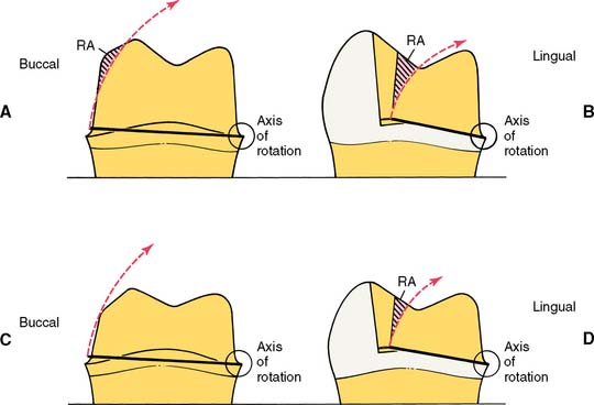
Fig. 7-40 Resistance form of partial and complete crowns. A, The buccoaxial wall (RA) of a complete crown should provide good resistance to rotation around a lingual axis. B, In a partial crown, resistance must be furnished by mesial and distal grooves. C, In a short or excessively tapered complete crown, resistance form is minimal because most of the buccal wall is missing. A mesiodistal groove should be placed to increase resistance form. D, Poor resistance form is less a problem in a short partial crown, if the grooves have sufficient definition. However, lack of retention form may indicate the need for complete coverage.
Physical properties of the luting agent
Resistance to deformation is affected by physical properties of the luting agent, such as compressive strength and modulus of elasticity. To satisfy American Dental Association/American National Standards Institute specification no. 96 (International Standards Organization specification no. 9917), the compressive strength of zinc phosphate cement must exceed 70 MPa* at 24 hours (Fig. 7-42). Glass ionomer cements and most resins have higher compressive strength, whereas polycarboxylates have similar values to those of zinc phosphate.102
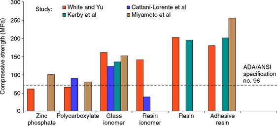
Fig. 7-42 Compressive strength of luting agents. Higher-strength values were reported in these studies113-116 with the resin cements and glass ionomers than with zinc phosphate or polycarboxylate. Resin-modified glass ionomer exhibited greater variation than other cements. ADA, American Dental Association; ANSI, American National Standards Institute.
(From Rosenstiel SF, et al: Dental luting agents: a review of the current literature. J Prosthet Dent 80:280, 1998.)
Increasing temperature has a dramatic effect on the compressive strength of luting agents, particularly weakening reinforced zinc oxide–eugenol cement (Fig. 7-43). An increase from room temperature (23° C) to body temperature (37° C) halves the compressive strength of reinforced zinc oxide-eugenol cements, and a rise in temperature to 50° C (equivalent to hot food) reduces the compressive strength by over 80%.103 Equivalent testing of more modern cements has not been reported.
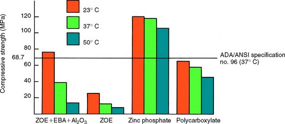
Fig. 7-43 Compressive strength of luting agents at different temperatures. ADA, American Dental Association; EBA, ethoxybenzoic acid; ZOE, zinc oxide–eugenol.
(Redrawn from Mesu FP: J Prosthet Dent 49:59, 1983.)
Zinc phosphate cements have a higher modulus of elasticity than do polycarboxylate cements, which exhibit relatively large plastic deformation.104 This may account for the observation that the retentive ability of polycarboxylate cement is more dependent on the taper of the preparation than is the retention with zinc phosphate cement.105
The factors that affect the resistance to displacement of a cemented restoration are summarized in Table 7-5.
Table 7-5 FACTORS INFLUENCING THE RESISTANCE OF CEMENTED RESTORATIONS
 |
Preventing Deformation
A restoration must have sufficient strength to prevent permanent deformation during function (Fig. 7-44); otherwise, it will fail (typically at the restoration-cement, or the metal-porcelain, interface). This may be a result of inappropriate alloy selection, inadequate tooth preparation, or poor metal-ceramic framework design (see Chapter 19).
Alloy selection
Although type I and type II gold alloys (see Chapter 22) are satisfactory for intracoronal cast restorations, they are too soft for crowns and fixed dental prostheses, for which type III or type IV gold alloys (or an appropriate low-gold alternative) are chosen. These are harder, and their strength and hardness can be further increased by heat treatment.
Metal-ceramic alloys with high noble metal content have a hardness equivalent to that of type IV gold alloys, whereas nickel-chromium alloys are considerably harder. These may be indicated when large forces are anticipated, such as with a long-span fixed dental prosthesis, although their use presents certain problems (see Chapter 19).
Adequate tooth reduction
Even the stronger alloys need sufficient bulk, however, if they are to withstand occlusal forces (see Figs. 8-4 and 9-1B).
Largely according to empirical data, there should be a minimum alloy thickness of about 1.5 mm over functional cusps (buccal in the mandible, lingual in the maxilla). The less stressed nonfunctional cusps can be protected with less metal (1 mm is adequate in most circumstances) for a strong and long-lasting restoration. Occlusal reduction should be as uniform as possible, following the cuspal planes of the teeth; this ensures that sufficient occlusal clearance is combined with preservation of as much tooth structure as possible. In addition, an anatomically prepared occlusal surface (Fig. 7-45) gives rigidity to the crown because of the “corrugated effect”106 of the planes.
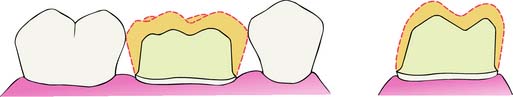
Fig. 7-45 Anatomic occlusal reduction is conservative of tooth structure and gives rigidity to the restoration.
When teeth are malaligned or overerupted, the occlusal surface needs to be prepared with the thickness requirements of the eventual restoration in mind. For example, a supraerupted tooth may need considerably more than 1.5 mm of reduction to establish adequate clearance in order to reestablish optimal occlusal form and the appropriate plane while ensuring adequate restoration thickness (Fig. 7-46). Diagnostic tooth preparation and waxing are helpful in determining the correct tooth reduction.
Margin design
Distortion of the restoration margin is prevented by designing the preparation outline form so that occlusal contact is avoided in this area. Keeping preparation margins approximately 1 to 1.5 mm away from occlusal contact areas satisfies this requirement. Also, tooth reduction should provide sufficient room for bulk of metal at the margin to prevent distortion. For example, as discussed previously, one disadvantage of the feather edge preparation is that the resulting thin layer of gold is not as strong as the comparatively thicker restoration of a chamfer preparation. When teeth have been prepared with increased taper, however, it is advisable to reduce margin width in order to maintain adequate dentin thickness between the axial preparation wall and the pulpal tissues.107
The grooves and ledges incorporated in a partial-coverage preparation provide essential strengthening for the casting; in particular, anterior pinledge retainers benefit from the resulting beamlike reinforcement that results (Fig. 7-47).
ESTHETIC CONSIDERATIONS
The restorative dentist should develop skill in determining the esthetic expectations of the patient. Most patients prefer their dental restorations to look as natural as possible. However, esthetic considerations should not be pursued at the expense of the prognosis of the patient’s long-term oral health or function.
At the initial examination, a full assessment is made of the appearance of each patient, noting which areas of which teeth show during speech, smiling, and laughing. The patient’s esthetic expectations must be discussed and related to oral hygiene needs and the potential for development of future disease. The final decision regarding an appropriate restoration can then be made with the full cooperation and informed consent of the patient.
Esthetic restorations include partial veneer crowns, which maintain an intact labial or buccal surface in original tooth structure; metal-ceramic restorations, which consist of a metal cast substructure that in visible areas has an esthetic porcelain veneer; and all-ceramic restorations.
All-Ceramic Restorations
Some of the most pleasing esthetic restorations are all-ceramic crowns, inlays, onlays, and veneers (see Chapter 25). They can mimic original tooth color better than the other restorative options. Although at somewhat greater risk of brittle fracture, the newest materials have improved physical properties and can be strengthened through the use of resin-bonded luting agents.
Not all ceramic crown preparations are conservative of tooth structure, as a wide 90-degree heavy chamfer margin must be prepared around the entire tooth to ensure increased material thickness and material strength. For the same reason, additional reduction on the lingual surface is needed for these restorations. A minimal material thickness of approximately 1 to 1.2 mm is necessary to ensure optimal esthetics. This limits the use of these restorations on faciolingually thin teeth and on teeth with large pulps, as in young individuals.
Metal-Ceramic Restorations
A compromised appearance of some metal-ceramic restorations (see Chapters 19 and 24) is often caused by insufficient porcelain thickness. On the other hand, adequate porcelain thickness is sometimes obtained at the expense of proper axial contour (such overcontoured restorations almost invariably lead to periodontal disease). In addition, the labial margin of a metal-ceramic crown is not always accurately placed. To correct all these deficiencies, certain principles are recommended during tooth preparation that ensure sufficient room for porcelain and accurate placement of the margins. Otherwise, good appearance would be achievable only at the expense of periodontal health.
Facial tooth reduction
If there is to be sufficient bulk of porcelain for appearance and metal for strength, adequate reduction of the facial surface is essential. The exact amount of reduction depends to some extent on the physical properties of the alloy used for the substructure, as well as on the manufacturer and the shade of the porcelain. A good color match for some restorations in older individuals typically requires a slightly greater porcelain thickness than is needed in younger patients. A minimum reduction of 1.5 mm typically is required for optimal appearance. Adequate thickness of porcelain (Fig. 7-48) is needed to create a sense of color depth and translucency. Shade problems are frequently encountered in maxillary incisor crowns at the incisal and cervical thirds of the restoration, where direct light reflection from the opaque layer can make the restoration appear very noticeable. Because opaque porcelains generally have a shade different from that of body porcelains, they often need to be modified with special stains in these areas108 (see Chapter 24).
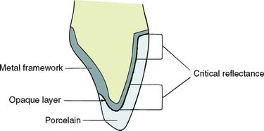
Fig. 7-48 Adequate porcelain thickness is essential for preventing direct light reflection from the highly pigmented opaque porcelain. The most critical areas are the gingival and incisal thirds; in practice, opaque modifying stains are often used in these areas.
(Redrawn from McLean JW: The Science and Art of Dental Ceramics, vol 1. Chicago, Quintessence Publishing, 1979.)
With very thin teeth (e.g., mandibular incisors), it may be impossible to achieve adequate tooth reduction without exposing the pulp or leaving a severely weakened tooth preparation. Under these circumstances, a less-than-ideal appearance may have to be accepted.
The labial surfaces of anterior teeth should be prepared for metal-ceramic restorations in two distinct planes (Fig. 7-49). If they are prepared in a single plane, insufficient reduction in either the cervical or the incisal area of the preparation results.
Incisal reduction
The incisal edge of a metal-ceramic restoration has no metal backing and can be made with a translucency similar to that of natural tooth structure. An incisal reduction of 2 mm is recommended for good esthetics. Excessive incisal reduction must be avoided because it reduces the resistance and retention form of the preparation.
Proximal reduction
The extent of proximal reduction is contingent on exact predetermination of the location of the metal-ceramic junction in the completed restoration. The proximal surfaces of anterior teeth look most natural if they are restored at the incisal edges, without metal backing. This allows some light to pass through the restoration in a manner similar to what occurs on a natural tooth (Fig. 7-50). Obviously, if the restoration is part of a fixed dental prosthesis, the need for connectors makes this impossible.
Labial margin placement
Supragingival margin placement has many biologic advantages. The restorations are easier to prepare properly and easier to keep clean. Nevertheless, subgingival margins may be indicated for esthetic reasons, particularly when the patient has a high lip line and when the use of a metal collar labial margin is contemplated.
The patient’s smile is observed as part of the initial examination (see Chapter 1). It is important to record which teeth and which parts of each tooth are exposed. Patients with a high lip line, which exposes considerable gingival tissue, present the greatest problem if complete crowns are needed. Where the root surface is not discolored, appearance can be restored with a metal-ceramic restoration with a supragingival porcelain labial margin (see Chapter 24). If the patient has a low lip line, a metal supragingival collar may be placed because the metal is not seen during normal function. Metal margins generally have a more accurate fit than porcelain margins.
However, it cannot be assumed that the patient will be happy with a supragingival metal collar just because the metal is not visible during normal function. Some patients have reservations about exposed metal, and the advantages of such supragingival margins must be carefully explained before treatment.
Metal collars can be hidden below the gingival crest, although there is some discoloration if the gingival tissue is thin. Successful margin placement within the gingival sulcus requires care to ensure that inflammation and/or recession, with resulting metal exposure, are avoided or minimized. The periodontium must be healthy before the tooth is prepared. If periodontal surgery is needed, the sulcular space should not be eliminated completely; rather, a postsurgical depth of about 2 mm should be the objective. Sufficient time should be allowed after surgery for the periodontal tissues to stabilize. Wise109 found that the gingival crest does not stabilize until 20 weeks after surgery (see Chapter 5).
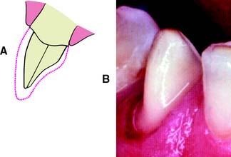
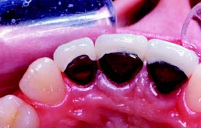
Margins should not be placed so far apically that they encroach on the attachment; extension to within 1.5 mm of the alveolar crest leads to bone resorption.110 The margin should follow the contour of the free gingiva, being further apical in the middle of the tooth and further incisal interproximally. A common error (Fig. 7-51) is to prepare the tooth so the margin lies almost in one plane, with exposure of the collar labially and irreversible loss of bone and papilla proximally.
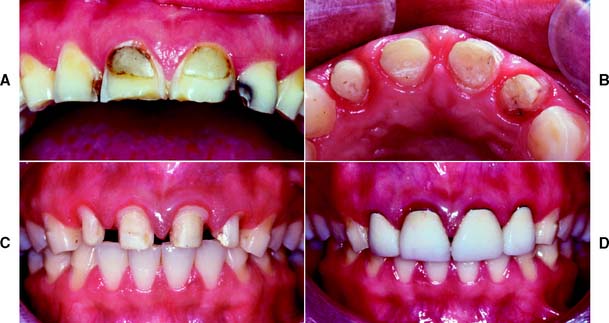
Fig. 7-51 Poor preparation design. A, These badly damaged incisors were treatment planned for metal-ceramic crowns. B and C, The apical margin of the preparation does not follow the free gingival contours. D, The restoration displays a metal collar labially, and the deep proximal margins have led to periodontal disease.
Partial-Coverage Restorations
Whenever possible, accomplishment of an esthetically acceptable result without the use of complete crowns is preferred, because tooth structure is conserved and because no restorative material can approach the appearance of intact tooth enamel. Esthetic partial-coverage restorations (see Chapter 10) depend on accurate placement of the potentially visible facial and proximal margins. Understandably, many patients do not readily accept a visible display of metal. If a partial-coverage restoration is poorly prepared, the patient may demand that it be replaced by a metal-ceramic crown, and the result is unnecessary loss of tooth structure and a greater potential for tissue damage.
Proximal margin
Precise placement of the proximal margins (particularly the mesial, generally more visible, margin) is crucial for the esthetic result of a partial-coverage restoration. The rule is to place the margin just buccal to the proximal contact area, where metal is hidden by the distal line angle of the neighboring tooth and yet provides adequate access to the tooth-restoration interface for plaque control. Tooth preparation angulation is critical and should normally follow the long axes of posterior teeth and the incisal two thirds of the facial surface of anterior teeth. If a buccal or lingual tilt is given to the tooth preparation, the likelihood that metal will be visible increases significantly (Fig. 7-52).
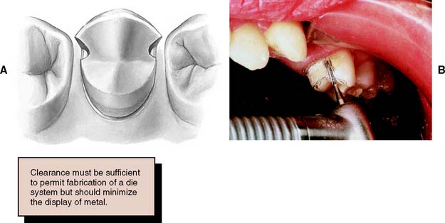
Fig. 7-52 A, Correct placement of the mesial margin of a partial-coverage restoration is essential for good esthetics. To allow proper access for finishing, the restoration must extend just beyond the contact area, but the metal must remain hidden from the casual observer. B, The tooth should be prepared in its long axis; otherwise, metal is displayed.
The distal margin of posterior partial-coverage restorations is less visible than the mesial margin. In this area, it is often advantageous to extend the preparation farther beyond the contact point for easier preparation and finishing of the restoration and easier access for oral hygiene.
Facial margin
The facial margin of a maxillary partial-coverage restoration should be extended just beyond the occlusofacial line angle. A short bevel is needed to prevent enamel chipping. A chamfer can be placed where appearance is less important (e.g., on molars) because this provides greater bulk of metal for strength.
If the buccal margin of metal is correctly shaped (Fig. 7-53), it does not reflect light to an observer. As a result, the tooth appears to be merely a little shorter than normal and not as though its buccal cusp is outlined in metal. If the buccal margin is skillfully placed so as to follow the original cuspal contour, the final restoration has an acceptable appearance.
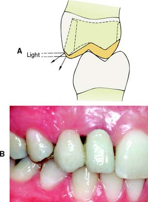
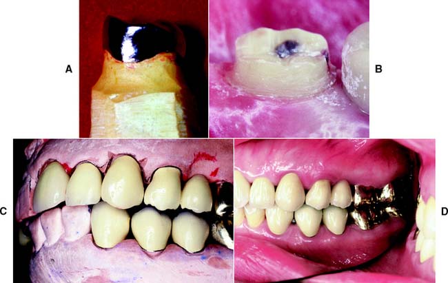
Fig. 7-53 A, The facial margin of a partial cast crown should be shaped so that light is not reflected directly to the observer. B, A three-unit fixed dental prosthesis. The mesial abutment is a canine, shaped to look like a lateral incisor. The distal abutment is a partial cast crown, which proved to be esthetically acceptable because the metal had been correctly contoured.
When mandibular partial cast crowns are made, metal display is unavoidable because the occlusal surface of mandibular teeth can be seen during speech. A chamfer, rather than a bevel, is recommended for the buccal margin because it provides a greater bulk of metal around the highly stressed functional cusp (Fig. 7-54). If the appearance of metal is unacceptable to the patient, a metal-ceramic restoration with porcelain coverage on the occlusal surface can be made.
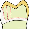
Fig. 7-54 A substantial chamfer is recommended for the functional buccal cusp of a mandibular partial cast crown. It provides greater bulk of metal in a stressed area.
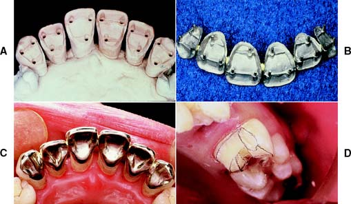
Anterior partial-coverage restorations can be fabricated to show no metal (Fig. 7-55), but their preparation requires considerable care. The facial margin is extended just beyond the highest contour of the incisal edge but not quite to the incisolabial line angle. Here the metal protects the tooth from chipping but is not visible.
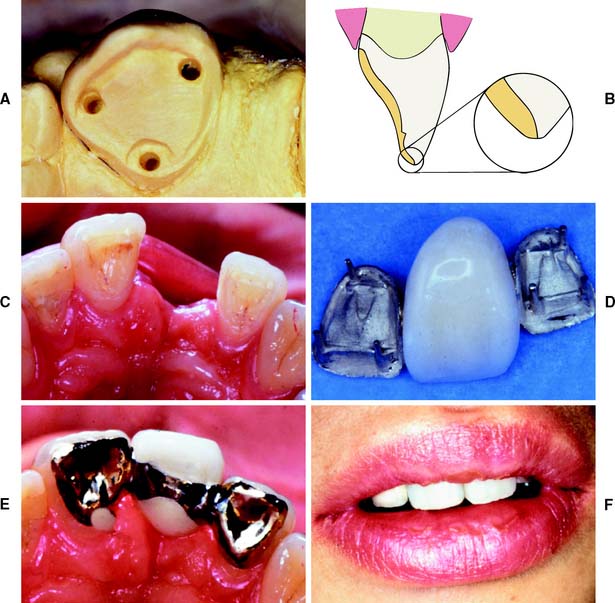
Fig. 7-55 A, Teeth can be prepared for partial-coverage restorations that do not show any metal. Success depends on very careful margin placement. B, The incisal edge is not completely covered. The restoration margin is located between the highest point of the incisal contour and the incisofacial angle. C, Intact anterior teeth on either side of an edentulous space. D, Three-unit fixed dental prosthesis with pinledge retainers and a metal-ceramic pontic. E, Occlusal view of fixed dental prosthesis. F, Acceptable esthetic result is obtained.
PLANNING AND EVALUATING TOOTH PREPARATIONS
Tooth preparation is a technically complicated and irreversible procedure. Thus, it is the practitioner’s responsibility to carry it out properly, every time. Mistakes are often difficult, if not impossible, to correct.
Diagnostic Tooth Preparations
Diagnostic tooth preparations are performed on articulated casts before the actual clinical preparation. They yield information with regard to the following:
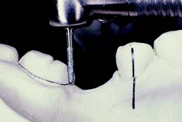
Fig. 7-56 Selecting the best path of placement for a fixed dental prosthesis with the aid of diagnostic tooth preparations.
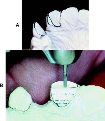
Fig. 7-57 A and B, Diagnostic tooth preparations are extremely helpful in determining the ideal reduction for esthetic partial-coverage restorations.
An important advantage of diagnostic tooth preparations is that the operator can practice each step of the intended restoration. Mistakes are not permanently destructive. Also, diagnostic preparations can be used in the prefabrication of interim restorations, significantly reducing appointment time duration at tooth preparation (the indirect/direct technique is described in Chapter 15).
Diagnostic waxing procedures
For all but the most straightforward prosthodontic treatment plans, a diagnostic waxing procedure (Fig. 7-58) should be performed. This is done on diagnostic tooth preparations and establishes the optimum contour and occlusion of the eventual prosthesis. The procedure is of particular benefit if the patient’s occlusal scheme or anterior (incisal) guidance requires alteration.
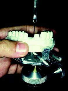
Evaluative procedures during tooth preparation
Each step of a tooth preparation should be carefully evaluated with direct vision or indirectly with a dental mirror. Alignment of multiple abutment teeth can be a special problem, and using the mirror helps to superimpose the image of adjacent abutment teeth. Complex preparations should be evaluated by making an alginate impression and pouring it in fast-setting stone. A dental surveyor (Fig. 7-59) can then be used to precisely measure the axial inclinations of the tooth preparation. The less experienced dentist may hesitate to make such an impression for fear of losing time. However, the information obtained often saves time in subsequent procedures by identifying problems that can then be addressed immediately. For tooth preparation, it is useful to learn to use the contra-angle handpiece as both a measuring and a cutting instrument. This is done by concentrating on the top surface of the turbine head, which is perpendicular to the shank of the bur. If the top surface is kept parallel to the occlusal surface of the tooth being prepared, the bur is automatically in the correct orientation (Fig. 7-60). To prevent undercuts or excessive convergence during axial reduction, the handpiece must be maintained at the same angulation. The correct taper is imparted by the diamond instrument. Keeping the turbine head at its correct angulation initially is often most effectively done by supporting it with a finger of the opposite hand.
Patient and Operator Positioning
Learning the proper patient and operator positions is as beneficial as learning the proper preparation steps. Of particular importance are the advantages of obtaining a direct view of the preparation, which is always preferred to an indirect or mirror view. However, certain areas (e.g., the distal surfaces of maxillary molars) cannot be seen directly.
Inexperience, coupled with a hesitation to move the patient’s head into a more favorable position, can unnecessarily complicate tooth preparation. For instance, having the patient rotate the head to the left or right side can considerably improve the visibility of molar teeth that are being prepared. In most instances, a direct view can be obtained by subtly changing the operator’s or the patient’s position. Having the patient open maximally does not necessarily provide the best view. If the jaw is partially open, the cheek may be retracted more easily (Fig. 7-61), and if the patient is encouraged to make a lateral excursion, the distobuccal line angle, together with the buccal third of the distal wall, may be seen directly. In practice, the mirror is essential only for visualizing a small portion of the distal surface. When a complete crown is prepared, the parts of the tooth most easily seen should be prepared first, leaving the other areas for preparation with the help of the mirror as a final stage.
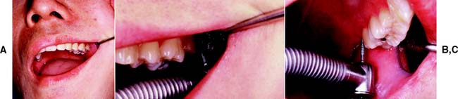
Fig. 7-61 Careful patient positioning can help obtain a direct view during tooth preparation. A, Often access is better if the mouth is not open maximally, because partial opening allows the cheek to be more easily retracted. B, Access to the buccal surface. C, Access to the palatal surface. A direct view is obtained by tilting the patient’s head.
Figure 7-62 shows patient and right-handed dentist positioned for tooth preparation of the less accessible maxillary posterior teeth.
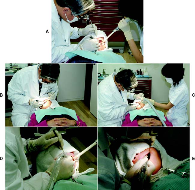
Fig. 7-62 A, Maxillary right posterior sextant. Buccal or buccal half of occlusal surface reduction. Operator is at the 9 to 11 o’clock position in relation to the chair. Patient turns head to left to improve direct vision. B, Maxillary right posterior sextant. Palatal or palatal half of occlusal surface reduction, including functional cusp bevel. Operator is at the 11 o’clock position. Patient turns head to right to improve direct vision. C, Maxillary left posterior sextant. Buccal or buccal half of occlusal surface reduction. Operator is at the 9 o’clock position. Patient turns head to right to improve direct vision. D, Maxillary left posterior sextant. Palatal or palatal half of occlusal surface reduction, including functional cusp bevel. Operator is at the 9 o’clock position. Patient turns head to left to improve direct vision. E, Maxillary left posterior sextant. Distal surface reduction. Operator is at the 9 o’clock position. Access is improved by having the patient tilt the head, partially close, and move the mandible in a left lateral excursion.
SUMMARY
The principles of tooth preparation can be categorized into biologic, mechanical, and esthetic considerations. Often these principles conflict, and the practitioner must decide how the restoration should be designed. One area may be given too much emphasis, and the long-term success of the procedure may be limited by a lack of consideration of other factors.
Experience helps in determining whether preparations are “complete.” Each tooth preparation must be measured by clearly defined criteria, which can be used to identify and correct problems. Diagnostic tooth preparations and evaluative impressions are often very helpful. The types of preparation described in the following chapters are explained in a step-by-step format. Understanding the pertinent theories underlying each step is crucial. Successful preparation can be obtained most easily by systematically following the steps. It is crucial to refrain from “jumping ahead” before the previous step has been evaluated and, if necessary, corrected. If the clinician proceeds too rapidly, precious chair time will be lost, and the quality of the preparation will probably suffer.
 GLOSSARY*
adaptation \ăd′ăp-tā′shun\ n (1610): 1: the act or process of adapting; the state of being adapted 2: the act of purposefully adapting two surfaces to provide intimate contact 3: the progressive adjustive changes in sensitivity that regularly accompany continuous sensory stimulation or lack of stimulation 4: in dentistry, (a) the degree of fit between a prosthesis and supporting structures, (b) the degree of proximity of a restorative material to a tooth preparation, (c) the adjustment of orthodontic bands to teeth
axial inclination \ăk′sē-al īn′kla nā′shun\ 1: the relationship of the long axis of a body to a designated plane 2: in dentistry, the alignment of the long axis of a tooth to a selected plane, often the horizontal plane
axis of preparation \ăk′s s ŭv pr
 p′a-rā′shun\: the planned line or path of placement and removal for a dental restoration
1bevel \bv′al\ n (1611): a slanting edge
2bevel \bv′al\ vt: the process of slanting the finish line and curve of a tooth preparation
bur \bûr\ n (14c): a steel or tungsten carbide rotary cutting instrument
bur head \bûr hd\ n (2005): the cutting portion of a dental bur
bur head length \bûr hd lngkth, lngth\: the axial dimension of the bur head
bur head shape \bûr hd shāp\ (2005): the geometrical outline form of the cutting surface edges, usually described successively by proximity from the shank to the tip end
bur shank \bûr shăngk\ n (2005): that component of a dental bur which fits into the hand piece; the shaft section of the dental bur that may be friction gripping or latch-type in form
butt \bŭt\v (14c): to bring any two flat-ended surfaces into contact without overlapping, as in a butt joint
1cham·fer \chăm′fer\ n: 1: a finish line design for tooth preparation in which the gingival aspect meets the external axial surface at an obtuse angle 2: a small groove or furrow 3: the surface found by cutting away the angle of intersection of two faces of a piece of material (i.e., stone, metal, wood): a beveled edge
2cham·fer \chăm′fer\ vt cham·fer·ing; cham·fers: 1: to cut a furrow in 2: to make a chamfer on; to cut or reduce to a chamfer; bevel 3: generally thought of as producing a curve from the axial wall to the cavosurface
chamfer angle \chăm′fer ăng′gel\ n: the angle between a chamfered surface and one of the original surfaces from which the chamfer is cut
clear·ance \klîr′ens\ n (1563) obs: a condition in which bodies may pass each other without hindrance. Also, the distance between bodies (GPT-4)
clinical crown \kln′-kel kroun\: the portion of a tooth that extends from the occlusal table or incisal edge to the free gingival margin
complete crown \k m-plēt kroun\: a restoration that covers all the coronal tooth surfaces (mesial, distal, facial, lingual, and occlusal)
convergence angle \kon-vûr′jens ăng′gel\: 1: the taper of a crown preparation 2: the angle, measured in degrees, formed between opposing axial walls when a tooth or teeth are prepared for single crowns or fixed dental prostheses. Usage- this term is best described as the total occlusal convergence
1crown \kroun\ n (12c): 1: the highest part, as the topmost part of the skull, head or tooth; the summit; that portion of a tooth occlusal to the dentinoenamel junction or an artificial substitute for this 2: an artificial replacement that restores missing tooth structure by surrounding part or all of the remaining structure with a material such as cast metal, porcelain, or a combination of materials such as metal and porcelain
2crown \kroun\ vt (12c): to place on the head, as to place a crown on a tooth, dental implant or tooth substitute—usage: implies fabrication of a restoration for a tooth on a natural tooth, dental implant and/or dental implant abutment
de·for·ma·tion \dē′fôr-mā′shun, df′-er-\ n (15c): the change of form or shape of an object
den·tin \dn′tn\ n (1840): a calcareous material similar to but harder and denser than bone that comprises the principle mass of the tooth—den·tin·al adj; also spelled den·tine \dn′tēn\
di·ver·gence \d-vûr′jens, dī-\ n (1656) 1: a drawing apart as a surface extends away from a common point 2: the reverse taper of walls of a preparation for a restoration—di·ver·gen·cy n, pl -cies\-cēz\ (1709)
divergence angle \d-vûr′jens ăng′gl\ (1998): the sum of the angles of taper of opposing walls of a tooth preparation that diverge away from each other
draw \drô\ vt (bef. 12c): the taper or convergence of walls of a preparation for a restoration; slang—DRAFT, DRAUGHT
ex·tra·coro·nal \k′stra-kôr′a-nal, kr′-, ka-rō′nal\ adj: that which is outside or external to, the crown portion of a natural tooth; e.g., an extracoronal preparation, restoration, partial or complete crown
extracoronal retainer \k′stra-kôr′a-nal, kr′-, ka-rō′nal r-tā′ner\: that part of a fixed dental prosthesis uniting the abutment to the other elements of a prosthesis that surrounds all or part of the prepared crown
finish line \fn′sh līn\ n (1899): 1: a line of demarcation determined by two points 2: (obs) the peripheral extension of a tooth preparation 3: the planned junction of different materials 4: (obs) the terminal portion of the prepared tooth
fit \ft\ v, fit·ted \ft′d\, also fit \ft\; fit·ting \ft′ng\ vt (1586): 1: to be suitable or to be in harmony with 2a: to conform correctly to the shape or size of 2b: to insert or adjust until correctly in place; to make or adjust to the correct size or shape, i.e., to adapt one structure to another, as the adaptation of any dental restoration to its site, in the mouth
groove \grōōv\ n: a long narrow channel or depression, such as the indentation between tooth cusps or the retentive features placed on tooth surfaces to augment the retentive characteristics of crown preparations
i·at·ro·gen·ic \ī-ăt′ra-jn′k\ adj (1924): resulting from the activity of the clinician; applied to disorders induced in the patient by the clinician
interocclusal clearance \n′ter-a-klōō′sal klîr′ans\: 1: the arrangement in which the opposing occlusal surfaces may pass one another without any contact 2: the amount of reduction achieved during tooth preparation to provide for an adequate thickness of restorative material
line angle \līn ang′gal\: the point of convergence of two planes in a cavity preparation
lingual inclination \lng′gwal n-kla-nā′shun\: deviation of the coronal portion of a tooth from the vertical plane toward the tongue
lin·guo·ver·sion \lng′gwa-vûr′zhun, -shun\ n: lingual or palatal position of a tooth beyond the normal arch form
long axis \lng ăk′ss\: a theoretical line passing lengthwise through the center of a body
mar·gin \mär′jn\ n (14c): the outer edge of a crown, inlay, onlay, or other restoration. The boundary surface of a tooth preparation and/or restoration is termed the finish line or finish curve
path of placement \păth, path ŭv plās′mant\: the specific direction in which a prosthesis is placed on the abutment teeth or dental implants
point angle \point ăng′gal\: in the development of a cavity preparation, that place of convergence of three planes or surfaces—comp LINE ANGLE
re·ten·tion \r-tn′shun\ n (15c): that quality inherent in the prosthesis acting to resist the forces of dislodgment along the path of placement—see DIRECT R., INDIRECT R.
retention arm \r-tn′shun ärm\: an extension that is part of a removable dental prosthesis and is used to aid in the fixation of the prosthesis; a part of a clasp
retention form \r-tn′shun form\: the feature of a tooth preparation that resists dislodgment of a crown in a vertical direction or along the path of placement
shoulder finish line \shl′dar fn′sh līn\ n: a finish line design for tooth preparation in which the gingival floor meets the external axial surfaces at approximately a right angle
su·pra·gin·gi·val \sōō′pra-jn′ja-val\ adj: 1: located above the gingiva 2: that portion of a natural or artificial tooth that is coronal to the gingival crest
ta·per : in dentistry, the convergence of two opposing external walls of a tooth preparation as viewed in a given plane. The extension of those average lines within that plane form an angle describe as the angle of convergence
1un·der·cut \ŭn′dur-kŭt\ n (1859) 1: the portion of the surface of an object that is below the height of contour in relationship to the path of placement 2: the contour of a cross-sectional portion of a residual ridge or dental arch that prevents the insertion of a dental prosthesis 3: any irregularity in the wall of a prepared tooth that prevents the withdrawal or seating of a wax pattern or casting
2un·der·cut \ŭn′dur-kŭt\ v (ca. 1598): to create areas that provide mechanical retention for materials placement
veneer \va-nîr′\ n (1702): 1: a thin sheet of material usually used as a finish 2: a protective or ornamental facing 3: a superficial or attractive display in multiple layers, frequently termed a laminate veneer
STUDY QUESTIONS
1 Qvist V, et al. Progression of approximal caries in relation to iatrogenic preparation damage. J Dent Res. 1992;71:1370.
2 Zoellner A, et al. Histobacteriology and pulp reactions to long-term dental restorations. J Marmara Univ Dent Fac. 1996;2:483.
3 Langeland K, Langeland LK. Pulp reactions to crown preparation, impression, temporary crown fixation, and permanent cementation. J Prosthet Dent. 1965;15:129.
4 Baldissara P, et al. Clinical and histological evaluation of thermal injury thresholds in human teeth: a preliminary study. J Oral Rehabil. 1997;24:791.
5 Ohashi Y. Research related to anterior abutment teeth of fixed partial denture. Shikagakuho. 1968;68:726.
6 Morrant GA. Dental instrumentation and pulpal injury. II. Clinical considerations. J Br Endod Soc. 1977;10:55.
7 Brännsträm M. Dentinal and pulpal response. II. Application of an air stream to exposed dentine, short observation period: an experimental study. Acta Odontol Scand. 1960;18:17.
8 Land MF, et al. SEM evaluation of differently shaped diamond burs after tooth preparation. Abstract #344 (oral presentation), AADR General Session. J Dent Res. 1997;76(special issue):56.
9 Laforgia PD, et al. Temperature change in the pulp chamber during complete crown preparation. J Prosthet Dent. 1991;65:56.
10 Hume WR, Massey WL. Keeping the pulp alive: the pharmacology and toxicology of agents applied to dentine. Aust Dent J. 1990;35:32.
11 Johnson GH, et al. Crown retention with use of a 5% glutaraldehyde sealer on prepared dentin. J Prosthet Dent. 1998;79:671.
12 Felton DA, et al. Effect of cavity varnish on retention of cemented cast crowns. J Prosthet Dent. 1987;57:411.
13 Mausner IK, et al. Effect of two dentinal desensitizing agents on retention of complete cast coping using four cements. J Prosthet Dent. 1996;75:129.
14 Going RE. Status report on cement bases, cavity liners, varnishes, primers and cleansers. J Am Dent Assoc. 1972;85:654.
15 Dahl BL. Effect of cleansing procedures on the retentive ability of two luting cements to ground dentin in vitro. Acta Odontol Scand. 1978;36:137.
16 Brännström M, Nyborg H. Cavity treatment with a microbicidal fluoride solution: growth of bacteria and effect on the pulp. J Prosthet Dent. 1973;30:303.
17 Watts A. Bacterial contamination and the toxicity of silicate and zinc phosphate cements. Br Dent J. 1979;146:7.
18 Dahl BL. Antibacterial effect of two luting cements on prepared dentin in vitro and in vivo. Acta Odontol Scand. 1978;36:363.
19 Mjör IA. Bacteria in experimentally infected cavity preparations. Scand J Dent Res. 1977;85:599.
20 Quarnstrom F, et al. A randomized clinical trial of agents to reduce sensitivity after crown cementation. Gen Dent. 1998;46(1):68.
21 Seltzer S, Bender IB. The Dental Pulp: Biologic Considerations in Dental Procedures, 2nd ed., Philadelphia: JB Lippincott; 1975:180.
22 Dowden WE. Discussion of methods and criteria in evaluation of dentin and pulpal responses. Int Dent J. 1970;20:531.
23 Sorensen JA. A rationale for comparison of plaque-retaining properties of crown systems. J Prosthet Dent. 1989;62:264.
24 Perel ML. Axial crown contours. J Prosthet Dent. 1971;25:642.
25 Han TJ, Takei HH. Progress in gingival papilla reconstruction. Periodontology 2000. 1996;11:65.
26 Silness J. Periodontal conditions in patients treated with dental bridges. III. The relationship between the location of the crown margin and the periodontal condition. J Periodont Res. 1970;5:225.
27 Karlsen K. Gingival reactions to dental restorations. Acta Odontol Scand. 1970;28:895.
28 Newcomb GM. The relationship between the location of subgingival crown margins and gingival inflammation. J Periodontol. 1974;45:151.
29 Bader JD, et al. Effect of crown margins on periodontal conditions in regularly attending patients. J Prosthet Dent. 1991;65:75.
30 Block PL. Restorative margins and periodontal health: a new look at an old perspective. J Prosthet Dent. 1987;57:683.
31 Ackerman MB. The full coverage restoration in relation to the gingival sulcus. Compendium. 1997;18:1131.
32 Felton DA, et al. Effect of in vivo crown margin discrepancies on periodontal health. J Prosthet Dent. 1991;65:357.
33 Byrne G, et al. Casting accuracy of high-palladium alloys. J Prosthet Dent. 1986;55:297.
34 Belser UC, et al. Fit of three porcelain-fused-to-metal marginal designs in vivo: a scanning electron microscope study. J Prosthet Dent. 1985;53:24.
35 Rosner D. Function, placement, and reproduction of bevels for gold castings. J Prosthet Dent. 1963;13:1160.
36 Rosenstiel E. The marginal fit of inlays and crowns. Br Dent J. 1964;117:432.
37 Hoard RJ, Watson J. The relationship of bevels to the adaptation of intracoronal inlays. J Prosthet Dent. 1976;35:538.
38 Shillingburg HTJr, et al. Preparation design and margin distortion in porcelain-fused-to-metal restorations. J Prosthet Dent. 1973;29:276.
39 Faucher RR, Nicholls JI. Distortion related to margin design in porcelain-fused-to-metal restorations. J Prosthet Dent. 1980;43:149.
40 Pascoe DF. Analysis of the geometry of finishing lines for full crown restorations. J Prosthet Dent. 1978;40:157.
41 Gavelis JR, et al. The effect of various finish line preparations on the marginal seal and occlusal seat of full crown preparations. J Prosthet Dent. 1981;45:138.
42 Hunter AJ, Hunter AR. Gingival crown margin configurations: a review and discussion. I. Terminology and widths. J Prosthet Dent. 1990;64:548.
43 Dykema RW, et al. Johnston’s Modern Practice in Crown and Bridge Prosthodontics, 4th ed., Philadelphia: WB Saunders; 1986:27.
44 Shillingburg HT, et al. Fundamentals of Fixed Prosthodontics, 3rd ed., Chicago: Quintessence Publishing; 1997:128.
45 Dimashkieh MR. Modified rotary design instruments for controlled finish line crown preparation. J Prosthet Dent. 1993;69:120.
46 Ramp MH, et al. Tooth structure loss apical to preparations for fixed partial dentures when using self-limiting burs. J Prosthet Dent. 1998;79:491.
47 Seymour K, et al. Assessment of shoulder dimensions and angles of porcelain bonded to metal crown preparations. J Prosthet Dent. 1996;75:406.
48 Hoffman EJ. How to utilize porcelain fused to gold as a crown and bridge material. Dent Clin North Am. 1965;9:57.
49 Richter-Snapp K, et al. Change in marginal fit as related to margin design, alloy type, and porcelain proximity in porcelain-fused-to-metal restorations. J Prosthet Dent. 1988;60:435.
50 Byrne G. Influence of finish-line form on crown cementation. Int J Prosthodont. 1992;5:137.
51 Syu JZ, et al. Influence of finish-line geometry on the fit of crowns. Int J Prosthodont. 1993;6:25.
52 Hamaguchi H, et al. Marginal distortion of the porcelain-bonded-to-metal complete crown: an SEM study. J Prosthet Dent. 1982;47:146.
53 Goodacre CJ, et al. Tooth preparations for complete crowns: an art form based on scientific principles. J Prosthet Dent. 2001;85:363.
54 Farah JW, et al. Effects of design on stress distribution of intracoronal gold restorations. J Am Dent Assoc. 1977;94:1151.
55 Walton JN, et al. A survey of crown and fixed partial denture failures: length of service and reasons for replacement. J Prosthet Dent. 1986;56:416.
56 Lindquist E, Karlsson S. Success rate and failures for fixed partial dentures after 20 years of service. I. Int J Prosthodont. 1998;11:133.
57 Rosenstiel E. The retention of inlays and crowns as a function of geometrical form. Br Dent J. 1957;103:388.
58 Jørgensen KD. The relationship between retention and convergence angle in cemented veneer crowns. Acta Odontol Scand. 1955;13:35.
59 Kaufman EG, et al. Factors influencing the retention of cemented gold castings. J Prosthet Dent. 1961;11:487.
60 Dodge WW, et al. The correlation of resistance and retention to convergence angle [Abstract no. 880]. J Dent Res. 1983;62:267.
61 Hovijitra S, et al. The relationship between retention and convergence of full crowns when used as fixed partial denture retainers. J Indiana Dent Assoc. 1979;58(4):21.
62 Wilson AH, Chan DC. The relationship between preparation convergence and retention of extracoronal retainers. J Prosthodont. 1994;3:74.
63 Nordlander J, et al. The taper of clinical preparations for fixed prosthodontics. J Prosthet Dent. 1988;60:148.
64 Ohm E, Silness J. The convergence angle in teeth prepared for artificial crowns. J Oral Rehabil. 1978;5(4):371.
65 Ayad MF, et al. Assessment of convergence angles of tooth preparations for complete crowns among dental students. J Dent. 2005;33:633.
66 Mack J. A theoretical and clinical investigation into the taper achieved on crown and inlay preparations. J Oral Rehabil. 1980;7:255.
67 Reisbick MH, Shillingburg HT. Effect of preparation geometry on retention and resistance of cast gold restorations. Calif Dent Assoc J. 1975;3:51.
68 Nicholls JI. Crown retention. I. Stress analysis of symmetric restorations. J Prosthet Dent. 1974;31:179.
69 Nicholls JI. Crown retention. II. The effect of convergence angle variation on the computed stresses in the luting agent. J Prosthet Dent. 1974;31:651.
70 Potts RG, et al. Retention and resistance of preparations for cast restorations. J Prosthet Dent. 1980;43:303.
71 Kishimoto M, et al. Influence of preparation features on retention and resistance. Part II: three-quarter crowns. J Prosthet Dent. 1983;49:188.
72 Galun EA, et al. The contribution of a pinhole to the retention and resistance form of veneer crowns. J Prosthet Dent. 1986;56:292.
73 Worley JL, et al. Effects of cement on crown retention. J Prosthet Dent. 1982;48:289.
74 Smith BGN. The effect of the surface roughness of prepared dentin on the retention of castings. J Prosthet Dent. 1970;23:187.
75 Arcoria CJ, et al. Effect of undercut placement on crown retention after thermocycling. J Oral Rehabil. 1990;17:395.
76 O’Connor RP, et al. Effect of internal microblasting on retention of cemented cast crowns. J Prosthet Dent. 1990;64:557.
77 Saito C, et al. Adhesion of polycarboxylate cements to dental casting alloys. J Prosthet Dent. 1976;35:543.
78 Chan KC, et al. Bond strength of cements to crown bases. J Prosthet Dent. 1981;46:297.
79 DeWald JP, et al. Crown retention: a comparative study of core type and luting agent. Dent Mater. 1987;3:71.
80 McComb D. Retention of castings with glass ionomer cement. J Prosthet Dent. 1982;48:285.
81 Arfaei AH, Asgar K. Bond strength of three cements determined by centrifugal testing. J Prosthet Dent. 1978;40:294.
82 Tjan AHL, Li T. Seating and retention of complete crowns with a new adhesive resin cement. J Prosthet Dent. 1992;67:478.
83 el-Mowafy OM, et al. Retention of metal ceramic crowns cemented with resin cements: effects of preparation taper and height. J Prosthet Dent. 1996;76:524.
84 Ayad MF, et al. Influence of tooth surface roughness and type of cement on retention of complete cast crowns. J Prosthet Dent. 1997;77:116.
85 Prati C, et al. Permeability of marginal hybrid layers in composite restorations. Clin Oral Investig. 2005;9(1):1.
86 Chersoni S, et al. Water movement in the hybrid layer after different dentin treatments. Dent Mater. 2004;20:796.
87 Jørgensen KD, Esbensen AL. The relationship between the film thickness of zinc phosphate cement and the retention of veneer crowns. Acta Odontol Scand. 1968;26:169.
88 Hembree JH, Cooper EW. Effect of die relief on retention of cast crowns and inlays. Oper Dent. 1979;4:104.
89 Gegauff AG, Rosenstiel SF. Reassessment of die-spacer with dynamic loading during cementation. J Prosthet Dent. 1989;61:655.
90 Carter SM, Wilson PR. The effect of die-spacing on crown retention. Int J Prosthodont. 1996;9:21.
91 Gibbs CH, et al. Limits of human bite strength. J Prosthet Dent. 1986;56:226.
92 Wiskott HW, et al. The relationship between abutment taper and resistance of cemented crowns to dynamic loading. Int J Prosthodont. 1996;9:117.
93 Trier AC, et al. Evaluation of resistance form of dislodged crowns and retainers. J Prosthet Dent. 1998;80:405.
94 Weed RM, Baez RJ. A method for determining adequate resistance form of complete cast crown preparations. J Prosthet Dent. 1984;52:330.
95 Wiskott HW, et al. The effect of tooth preparation height and diameter on the resistance of complete crowns to fatigue loading. Int J Prosthodont. 1997;10:207.
96 Dodge WW. The effect of convergence angle on retention and resistance form. Quintessence Int. 1985;16:191.
97 Shillingburg HT, et al. Fundamentals of Fixed Prosthodontics, 3rd ed., Chicago: Quintessence Publishing; 1997:120.
98 Woolsey GD, Matich JA. The effect of axial grooves on the resistance form of cast restorations. J Am Dent Assoc. 1978;97:978.
99 Parker MH, et al. New guidelines for preparation taper. J Prosthodont. 1993;2:61.
100 Hegdahl T, Silness J. Preparation areas resisting displacement of artificial crowns. J Oral Rehabil. 1977;4:201.
101 Proussaefs P, et al. The effectiveness of auxillary features on a tooth preparation with inadequate resistance form. J Prosthet Dent. 2004;91:33.
102 Rosenstiel SF, et al. Dental luting agents: a review of the current literature. J Prosthet Dent. 1998;80:280.
103 Mesu FP. The effect of temperature on compressive and tensile strengths of cements. J Prosthet Dent. 1983;49:59.
104 Branco R, Hegdahl T. Physical properties of some zinc phosphate and polycarboxylate cements. Acta Odontol Scand. 1983;41:349.
105 McLean JW. Polycarboxylate cements: five years’ experience in general practice. Br Dent J. 1972;132:9.
106 Guyer SE. Multiple preparations for fixed prosthodontics. J Prosthet Dent. 1970;23:529.
107 Doyle MG. The effect of tooth preparation design on the breaking strength of Dicor crowns: 3. Int J Prosthodont. 1990;3:327.
108 McLean JW. The Science and Art of Dental Ceramics, vol 1. Chicago: Quintessence Publishing. 1979:136.
109 Wise MD. Stability of gingival crest after surgery and before anterior crown placement. J Prosthet Dent. 1985;53:20.
110 Palomo F, Kopczyk RA. Rationale and methods for crown lengthening. J Am Dent Assoc. 1978;96:257.
111 Gorodovsky S, Zidan O. Retentive strength, disintegration, and marginal quality of luting cements. J Prosthet Dent. 1992;68:269.
112 Mojon P, et al. Maximum bond strength of dental luting cement to amalgam alloy. J Dent Res. 1989;68:1545.
113 Kerby RE, et al. Some physical properties of implant abutment luting cements. Int J Prosthodont. 1992;5:321.
114 Cattani-Lorente M-A, et al. Early strength of glass ionomer cements. Dent Mater. 1993;9:57.
115 Miyamoto S, et al. Study on fatigue toughness of dental materials. I. Compressive strength on various luting cements and composite resin cores. Nippon Hotetsu Shika Gakkai Zasshi. 1989;33:966.
116 White SN, Yu Z. Compressive and diametral tensile strengths of current adhesive luting agents. J Prosthet Dent. 1993;69:568.