21 RETAINERS FOR PARTIAL REMOVABLE DENTAL PROSTHESES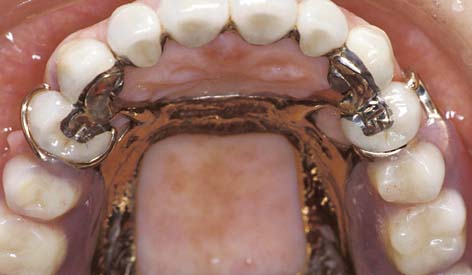
There exist different philosophies regarding the need for fabrication of cast restorations for abutment teeth before fabrication of a partial removable dental prosthesis (partial RDP). Some authors advocate making such removable prostheses with a minimum of mouth preparation. They do not suggest the routine use of cast restorations for abutment teeth but prefer to modify the remaining natural dentition through enamoplasty and/or addition of composite resin. This has the advantage of reducing both treatment time and expense. Other authors, however, point to the advantages of using cast restorations on abutment teeth, suggesting that through precise shaping of the axial contours of such restorations, the masticatory and retentive forces can be directed more favorably through appropriate use of occlusal rest seats and guide planes. In addition, cast retainers permit incorporation of intracoronal rest seats or precision attachments, which can offer significant esthetic advantages over clasp retained partial RDPs. Use of cast crowns also allows splinting of abutment teeth with resultant reduction of mobility.1
The correct choice of treatment for any patient depends on a thorough history and examination and an accurate diagnosis and prognosis (see Chapter 1). Decisions concerning the restoration of abutment teeth involve many factors—caries, existing restorations, tooth vitality, shape and angulation, oral hygiene, and cost and experience—that must be assessed and evaluated. Only then is the selected treatment likely to achieve the planned outcome that is based on the functional requirements of the patient.
TREATMENT PLANNING
The fabrication of a precisely fitting partial RDP is one of the more challenging tasks in restorative dentistry. Without a careful all-inclusive diagnosis and well-designed treatment plan, the chances of success are minimal. Patients who require a removable prosthesis usually have sustained extensive damage as a consequence of caries, periodontal disease, or trauma and may have extensive fixed and removable prosthodontic treatment needs (Fig. 21-1) They also may exhibit acquired or congenital intraoral defects. As a result of prolonged loss of arch integrity, there may be drifting or tipping, and the occlusion is often less than ideal.
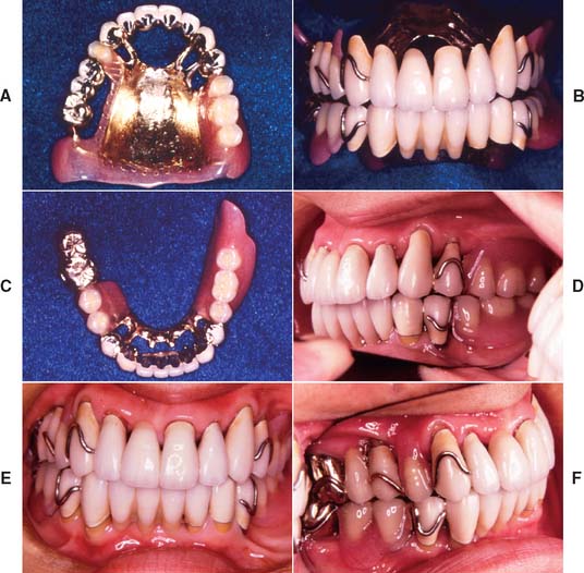
Fig. 21-1 A to F, The patient presented with extensive periodontal disease; several posterior teeth were removed. A combination of fixed and removable prostheses was used.
Treatment plans that include a removable prosthesis may require additional diagnostic procedures besides those described in Chapters 1 and 2. Accurate diagnostic casts mounted in centric relation are extremely important. If all posterior teeth are absent, it is much more difficult to relate opposing diagnostic casts, and stable record bases must be made under these circumstances (Fig. 21-2). The necessary degree of stability can be obtained only if such record bases are fabricated on the cast that is to be articulated.
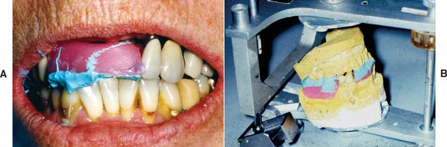
Fig. 21-2 Where multiple teeth are missing, a clasp-retained record base with wax rims (used here with zinc oxide–eugenol paste) should be used to ensure accurate articulation (A and B). This minimizes the risk of tipping of the casts in relation to one another.
The use of a dental surveyor (Fig. 21-3) is essential during treatment planning for the following reasons:
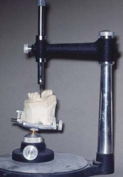
Fig. 21-3 A dental surveyor is essential during treatment planning and in designing retainers for partial removable dental prostheses.
The most appropriate anteroposterior and mediolateral tilt of the cast must be selected. Careful analysis is essential because a compromise between the requirements of an ideal tooth preparation (see Chapter 7) and the requirements for a particular tooth to be used as an abutment to support and retain an RDP is often necessary. The path of placement of the RDP is the most important factor in determining how much tooth reduction is needed to meet mechanical and esthetic requirements simultaneously (Fig. 21-4).
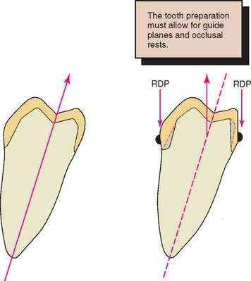
Fig. 21-4 A, Normal tooth preparation for a complete cast crown. The path of placement is in the long axis of the tooth. B, Modified tooth preparation for a partial removable dental prosthesis (RDP) retainer with lingual guide planes. This preparation has a more buccal path of placement.
When the diagnostic cast is surveyed, the anteroposterior tilt should be established first. The lateral inclination is then determined. The operator should focus on the relative alignment of selected abutment teeth, any tissue undercuts, and the available occlusocervical dimension for anticipated proximal and reciprocal guide planes. The feasibility of recontouring axial walls and the possible consequences of such recontouring must also be considered. For instance, it may be necessary to treat a malposed tooth orthodontically or endodontically if recontouring is not feasible. Similarly, removal of a tooth that unnecessarily complicates partial RDP design should be considered and carefully weighed against the effect of that decision on the stability of the prosthesis. If future loss of an already compromised tooth would render the partial RDP useless, it may be better to remove that tooth before initiating any prosthetic treatment.
When a patient has lost anterior teeth, the path of placement of a partial RDP should be parallel to the proximal surfaces of the abutment teeth adjacent to the space (Fig. 21-5). This results in superior esthetics because it minimizes the space between the artificial and natural teeth. Sometimes esthetics can be improved by use of a rotational placement path.2
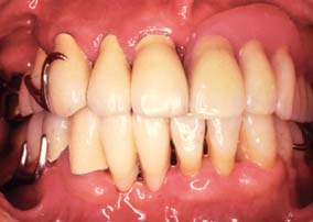
Fig. 21-5 The appearance of an anterior partial removable dental prosthesis is improved by careful selection of the path of placement.
Apparently complex decisions as to the best combination of tooth preparation and path of placement can be greatly simplified through diagnostic tooth preparation, waxing, and denture tooth setting (Figs. 21-6 and 21-7). These trial procedures on diagnostic casts help determine how to achieve the best mechanical and esthetic result without deviating from the principles of occlusion or making excessively bulky restorations that inevitably cause periodontal complications. The concept is to determine the precise end point in regard to occlusion and appearance with interchangeably articulator-mounted casts of the pretreatment and posttreatment condition, before treatment is initiated. The use of such cross-mounted casts (see also Chapter 3) also enables the treatment sequence to be simplified by allowing one arch to be treated at a time. The restorations on the first arch to be restored are fabricated against the diagnostically waxed opposing cast (Fig. 21-8; see also Fig. 3-34).
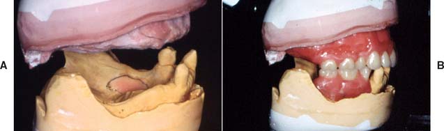
Fig. 21-6 Diagnostic mounted casts and waxing are essential prerequisites for extensive prosthodontic care. A, Diagnostically mounted casts. B, Diagnostic tooth arrangement.
(Courtesy of Dr. N. L. Clelland.)
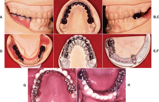
Fig. 21-7 Diagnostic tooth preparation and waxing are especially valuable in treating patients who require a combination of fixed and removable prosthodontics. A to D, Diagnostic waxing. E and F, Fixed prostheses. G and H, Completed restorations. Mandibular partial removable dental prosthesis has cast metal occlusal surfaces.
(Courtesy of Dr. J. H. Bailey.)
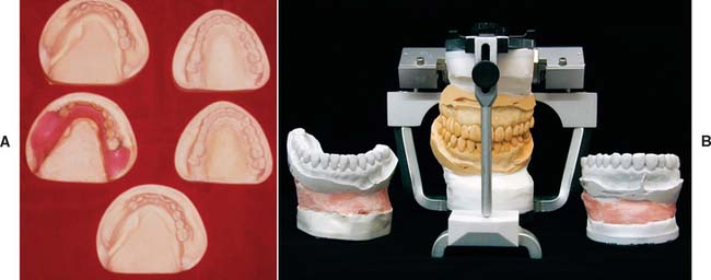
Fig. 21-8 Cross-mounted casts are used to simplify complex prosthodontic treatments. One set of casts is waxed to the end point of treatment, whereas the other set is left unaltered to enable the definitive casts to be mounted. An additional cast is needed for surveying a removable prosthesis. A, Casts needed for treating a patient who required a maxillary fixed prosthesis opposed by mandibular fixed and removable prostheses (see Fig. 21-7). B, The duplicated casts are mounted in the identical relationship on an articulator. Treatment can now be undertaken in phases. First the mandibular teeth are prepared, and a definitive cast is obtained. This is mounted against the maxillary unaltered cast, which is then replaced by the identically oriented, diagnostically waxed cast for the laboratory fabrication of the mandibular fixed prosthesis. (See also Fig. 3-34.)
(A, Courtesy of Dr. J. H. Bailey.)
Prerequisites for Success
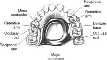
The clinician and laboratory technician must have a good understanding of partial RDP design (Fig. 21-9). An in-depth discussion of the approaches to framework design is beyond the scope of this text. Instead, the modifications that must be incorporated in the cast restoration to accommodate a partial RDP are considered.
Design
Many concepts of partial RDP design have been advocated. Regardless of the concept selected, the operator needs a keen understanding of the requirements placed on fixed retainers. The design should allow the forces developed during placement, removal, and function to be so directed as to cause the least harm to the remaining dentition. The proposed design (Fig. 21-10) should be carefully sketched at the initial treatment planning stage. In general, this reveals any existing problems. Each fixed restoration should be designed to be fully compatible with the removable prosthesis while concurrently meeting all criteria to properly fulfill the functional requirements of mastication and facilitating the performance of oral hygiene. Often, decisions made about the path of place-ment of the partial RDP necessitate removal of additional tooth structure in order to maintain the minimally required material thickness for the fixed prosthesis.
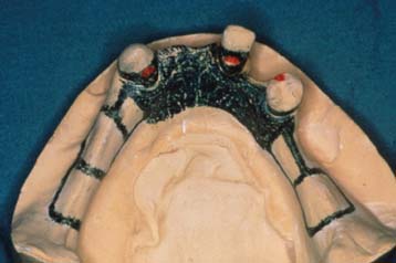
Fig. 21-10 Initial partial removable dental prosthesis design sketched on the diagnostic cast.
(Courtesy of Dr. N. L. Clelland.)
Denture bases
The denture base areas are shaped to avoid interference with the abutment retainer during placement and removal. Therefore, the fixed prosthesis determines the denture base configuration, rather than vice versa.
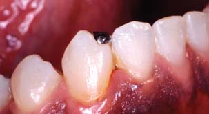
Occlusal rest seat
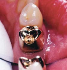
The rest seat (Fig. 21-11) is the prepared recess in a tooth or restoration created to receive the occlusal, incisal, cingulum, or lingual rest. The occlusal rest of the partial RDP is the rigid extension that contacts the occlusal surface of a tooth or restoration. The occlusal rest of a partial RDP should fit precisely into the corresponding rest seats on the retainers. To reduce laterally directed forces, the rest seats should be spoon-shaped. The junction between the internal aspect of the rest seat and the proximal guide plane should be rounded to minimize stress on the framework and thereby reduce the chance of partial RDP fracture at the occlusal rest–minor connector interface.
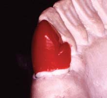
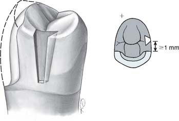
Occlusal rest seats are most predictably placed in healthy enamel or cast metal. If they are placed in weaker materials such as amalgam, composite resin, or dental porcelain, fracture or distortion is likely to result. The size of the rest seat has been a matter of controversy. Ordinarily, if crowns are made, a No. 8 round bur produces an ideally sized rest in the wax pattern. On small teeth under normal loading, a No. 6 round bur can provide adequate space (Fig. 21-12). On anterior teeth, a cingulum rest seat should be created to support the removable prosthesis. Rests that are convex mesiodistally and resemble a V-shaped groove labiolingually (Fig. 21-13) have proven successful in clinical practice. This configuration prevents displacement of the abutment while simultaneously assisting in directing forces more parallel to its long axis. Unfortunately, a distinct cingulum rest of adequate size can rarely be placed in the cingulum of an unrestored tooth without penetrating through the enamel.3 Sometimes a pin-retained or resin-bonded restoration4 is used to provide a cingulum rest.* An incisal rest may be used on unrestored mandibular canines (Fig. 21-14). This provides good support for the partial RDP but may be unacceptable esthetically. When a rest is placed on a metal-ceramic restoration, adequate thickness of metal must remain between the lateral walls of the occlusal rest seat and the porcelain-metal junction. About 1 mm is sufficient. Similarly, a minimal metal thickness of 1 mm between the rest seat and the occlusal aspect of the prepared tooth is advisable. To minimize the risk of fracture, an occlusal rest seat should not be placed directly on porcelain.
Minor connectors
The minor connectors of a partial RDP (Fig. 21-15) are the connecting link between the major connector or base of a partial RDP and the other units of the prosthesis, such as the clasp assembly, indirect retainers, occlusal rests, and cingulum rests. They join the rest seats and the clasps to the major connector and should fit intimately against the proximal guide plane on the cast restoration. The guide plane should be as long as possible occlusocervically and should follow the normal configuration of the tooth buccolingually. All proximal guide planes should parallel each other.
Clasp retention
The clasp engages a portion of the tooth surface and either enters an undercut for retention or remains entirely above the height of contour to act as a reciprocating element. In general, it is used to stabilize and retain an RDP. The amount of retention is related to, among other things, the configuration of the retentive arm, the material from which the clasp is made, and the extent of the undercut into which it is placed and from which it is dislodged when the partial RDP is taken out of the mouth.
Partial RDP frameworks are usually fabricated from base metal alloys, although some dentists prefer titanium or even an American Dental Association type IV gold alloy. In addition to conventional cast clasps, wrought retention clasp arms can be made of a platinum-gold-palladium or nickel-chromium alloy wires.
The modulus of elasticity of the base metals is considerably higher than that of a type IV gold alloy. Hence, shallower retentive undercuts, on the order of 0.12 to 0.25 mm (0.005 to 0.010 inch), can be used with the former. Undercuts of 0.25 to 0.50 mm (0.010 to 0.020 inch) can routinely be used with clasps made of either type IV gold or wire.
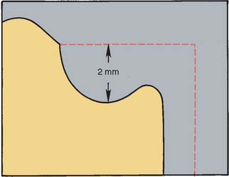
When a clasp is in its normal position with the partial RDP fully seated, it should fit in a passive manner against the retainer; simultaneously, it should be at least 2 mm occlusal to the crest of the free gingiva so that it does not interfere with maintenance of periodontal health. This means that the survey line, a line produced on a cast by a surveyor marking the greatest prominence of contour in relation to the planned path of placement of a restoration, must not be placed too far cervically.
Likewise, the height of contour must not be placed too far occlusally, or binding of the retentive arm may occur during RDP placement. Ideally, it should be within the middle third of the retentive surface of the retainer. A properly contoured surface enables the retentive arm to flex gradually along the path of placement. Only the terminal third of the retentive arm should be placed gingival to the survey line (Fig. 21-16). If more than the terminal third of the retentive arm is placed cervical to the height of contour, this may impede placement and removal of the RDP.

Fig. 21-16 The shape of the survey line is influenced by the material selected for the clasp. A, Cast clasp. Only the terminal third engages the undercut. B, Wrought clasp. The terminal half is retentive.
A typical survey line for occlusally approaching clasps has an undulating configuration somewhat reminiscent of the letter S, with its most gingival portion adjacent to the minor connector. If a gingivally approaching clasp is used, the undercut may be immediately adjacent to the proximal guide plane, although with the popular rest, proximal plate, and I-bar (RPI) design it is placed at or mesial to the midline of the tooth.7 Several factors—rest seat location, origin of the clasp, tissue undercuts, and degree of clasp encirclement—influence the actual configuration of the survey line for individual retainers.
Reciprocation
Reciprocation is the mechanism by which lateral forces generated by a retentive clasp passing over a height of contour are counterbalanced (Fig 21-17). This is usually done by a reciprocal clasp that passes along a reciprocal guiding plane. The reciprocal clasps have two functions: They guide the prosthesis into place upon insertion, and they support the abutments against horizontal forces exerted by the flexing retentive arms. The retentive arms should flex rather than displace the abutments laterally. Guide planes are needed on the crowns to allow for successful reciprocation. These should extend from the proximal guide plane to an area directly opposite the terminal position of the retentive clasp. Reciprocal clasps must contact the guide plane before the retentive arms start to flex, so that the periodontium is protected against excessive lateral loading.
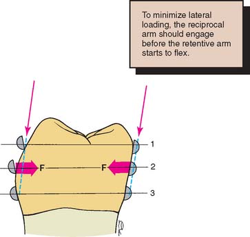
Fig. 21-17 Reciprocal arms prevent harmful lateral forces from being generated by the retentive arms during placement of a partial removable dental prosthesis (RDP). 1, Initial contact of the retentive arm; the reciprocal arm is in passive contact. 2, Maximum flexure of the retentive arm; the forces exerted (F) are resisted by the reciprocal clasp. 3, The partial RDP fully seated; both the retentive and the reciprocal clasps should be in passive contact.
TOOTH PREPARATION
After the proposed path of placement for the partial RDP has been determined and any necessary enamel modifications made, the teeth requiring abutment crowns can be prepared (Fig. 21-18). Making complete crowns is often necessary, but when facial contour does not require modification, partial coverage may sometimes be used.

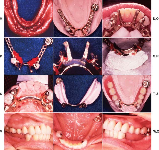
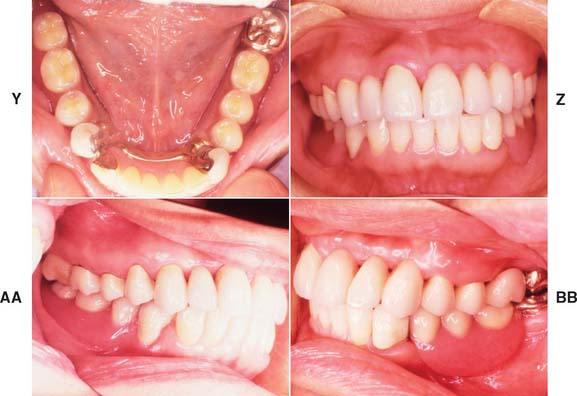
Fig. 21-18 Integration of fixed and removable prosthodontic treatment involving intracoronal rest seats. A and B, A patient with extensive previous restorative treatment required replacement with a combination of fixed and removable prostheses. C and D, After mouth preparation, the teeth have been prepared for fixed retainers. E and F, Definitive casts. G and H, A diagnostic setup is used to develop the correct occlusal plane as all restorations are waxed simultaneously. I to K, After fabrication and adjustment of the fixed prostheses, the maxillary restorations are cemented. L, The mandibular restorations are provisionally stabilized, and the partial removable dental prosthesis (RDP) impression is made. M, The mandibular restorations are provisionally stabilized, and the partial removable dental prosthesis (RDP) impression is made. N and O, The castings are retrieved, and the RDP framework is fabricated with two stabilizing arms on the lateral incisors to provide stability before the attachments are soldered onto the frame. P and Q, Autopolymerizing resin is used to relate the cast intracoronal rest seats to the RDP framework. R and S, The RDP frame is invested, with the attachments, and soldered, after which it is fitted back onto the master cast. T and U, After clinical verification of the fit, a wash impression is used to generate an altered cast, and the denture teeth are set. V to X, All retainers are now cemented. Y and Z, Occlusal and frontal views with the partial RDP in place. AA and BB, Left and right lateral views of the completed treatment.
Path of Placement
Careful planning is required when the path of placement of tooth preparations for RDP retainers is selected. Although conventional crowns generally have a path in the long axis of the tooth, partial RDP retainers may not. Surfaces where both guide planes and reciprocal planes are planned, as well as areas that require survey lines in the gingival third, typi-cally need to be “overprepared” in relation to the ideal conservative technique used on individual teeth. Because of the lingual inclination of mandibular molars, reducing them slightly more in the occlusal two thirds of the lingual axial surface is often necessary to allow the development of lingual guide planes that parallel each other across the dental arch.
Similarly, the axial reduction of surfaces adjacent to an edentulous ridge often involves removal of additional tooth structure. Care must be taken that these modifications do not lessen the retention form excessively, because during denture removal, the retainers are usually subjected to forces parallel to their path of placement, and retention becomes even more important. Additional features (e.g., grooves, boxes, pinholes) are frequently needed. It is certainly not mandatory that all retainers for a partial RDP have identical paths of placement.
Rest Seats
An adequate amount of tooth structure must be removed to allow for a minimum metal thickness of 1 mm in the area of an occlusal rest seat. To achieve adequate reduction, some dentists prepare a rest seat in the tooth before starting the retainer preparation. They then use 1-mm reduction grooves to ensure adequate thickness. Although this approach can work well, problems may occur if it becomes necessary to alter the position of the rest seat during the laboratory phase. Preference therefore should be given to the slightly less conservative approach seen in Figure 21-19 because being able to move the rest seat during the laboratory phase can be extremely helpful. Often esthetic needs, such as the interproximal extent of a cut-back for a metal-ceramic restoration, can be assessed only on the laboratory bench during waxing procedures.
Axial Contours
When a crown is to serve as a partial RDP abutment, modifications may be necessary in the normal axial reduction. The extent of additional axial reduction depends on the RDP design (see Fig. 21-9).
Additional tooth reduction is necessary if a retainer must be undercontoured with regard to the original tooth form to accommodate proximal or reciprocal guide planes and to allow the nonretentive part of an occlusally approaching clasp to be positioned as far gingivally as possible. (Again, diagnostic preparations and diagnostic waxing procedures often prove very helpful in assessing the need for additional axial reduction.)
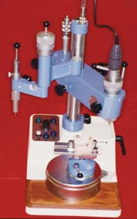
Another possible advantage of providing an abutment crown is the opportunity to shape the axial contours to accommodate the partial RDP clasps within the normal crown contours (Fig. 21-20). Although this allows for a less bulky removable prosthesis contour, it requires additional axial reduction. The use of a precision machine-tool milling device (see Fig. 21-27) is essential for these restorations.
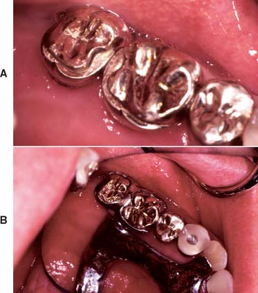
Fig. 21-20 Abutment crowns contoured to precisely receive the partial removable dental prosthesis (RDP) clasp. A, The cast crowns have received milled-in shelves that permit the partial RDP clasp to recess into the coronal form of the restored tooth. B, Partial RDP in place.
(Courtesy of Drs. K. Seckler and J. Janaowski.)
IMPRESSION MAKING
Because of the relative interdependence of partial RDP abutment preparations, a diagnostic irreversible hydrocolloid impression should be made after the preparations have been completed. This is poured in accelerated-setting stone or plaster. The resulting cast is then surveyed and the need for any further modifications is determined; such modifications can then be incorporated with minimum loss of chair time. The same cast can also be used for fabricating the interim restorations (see Chapter 15). A definitive impression is obtained with either an elastomeric or a reversible hydrocolloid technique, as described for conventional restorations (see Chapter 14).
Occlusal Records
A record base with wax rims is needed to articulate the casts unless an adequate number of posterior teeth are present to relate the opposing casts with a conventional centric relation record.
Because a record base is stable only on the cast from which it was made, it should not be fabricated in advance. Therefore, an additional patient visit must be planned to obtain an interocclusal record. The maxillary cast orientation is transferred by means of a facebow to the articulator, and the mandibular cast is articulated in the usual manner.
WAX PATTERN FABRICATION
Waxing partial denture abutments to optimally meet all requirements can be difficult, even for experienced operators. The need for good occlusion, anatomic form, and proper contours for plaque control often appears to conflict with the need for guide planes and retentive undercuts. Careful analysis is essential at the treatment planning stages, when a diagnostic waxing procedure can prove helpful. An organized approach to waxing partial RDP retainers must be maintained. The wax patterns are made in the usual way (see Chapter 18), creating normal axial form and embrasures and allowing for optimum distribution of the forces of occlusion. This is followed by adjustment of the axial walls to accommodate the survey line and guide planes. The resulting occlusal table typically has a reduced size in comparison with a pattern that is shaped to optimal anatomic form, which affects resulting occlusal form. The rest seats are placed as the final step in this process, immediately before reflowing in the margins and investing (see Chapter 22).
Survey Line
When normal coronal contour has been established in wax, the cast is removed from the articulator and placed on the surveyor (Fig. 21-21). The preliminary path of placement that was established during the treatment planning and tooth preparation phases may require slight modification. However, a minor alteration is all that should be necessary, and it often compensates for small, previously unrecognized errors that may have occurred at the tooth preparation stage.
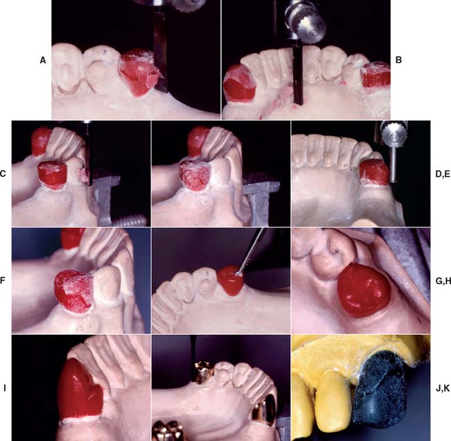
Fig. 21-21 Waxing partial removable dental prosthesis retainers. A, After the path of placement has been established, the carving attachment of the surveyor is used to make a 2- to 4-mm-wide band on the pattern. B, Note that the band includes the proximal and lingual walls of the pattern where the proximal and reciprocal guide planes, respectively, will be established. C, The band is carried onto the facial surface, where the retentive clasp is to be placed. Viewed from the occlusal aspect when complete, the band remains within the normal anatomic contour. D, The pattern is dusted with zinc stearate or powdered wax, and the desired survey line is scribed. E, After excess wax has been carved away occlusally and gingivally to create the desired contour, the undercut gauge is used to verify that the proper amount of wax has been removed. F, After smoothing and blending of the various surfaces, the pattern is again dusted with powder, and the configuration of the final survey line is verified. G, Then a round bur is used to place the occlusal rest seat. On premolars, a No. 6 bur is adequate; on molars, a No. 8 may be used. H, At least 1 mm of wax is maintained around the perimeter of the rest seat. I, A cingulum rest seat on a canine pattern can be carved with conventional waxing instruments. The lingual aspect of the rest seat must withstand lingual displacement. Mesiodistally, the rest seat is slightly curved, with the highest point in the middle of the pattern. J, After casting, the crowns are evaluated, and any adjustments are made to refine the height of contour, guide planes, and occlusal rest seats. K, Typical survey line for a wrought clasp. Note that the distal half of the clasp can easily be placed above the height of contour. The terminal half engages the undercut. A sufficiently long trajectory must remain incisal to the height of contour to allow gradual flexing of the clasp.
A survey line can be relocated by tilting the cast (e.g., a mesial undercut enlarged by increasing the mesial tilt, a buccal survey line moved further occlusally by increasing the tilt toward the buccal surface). When the cast tilt for the final path of placement has been selected, the cast is marked at three points (some technicians also mark the side of the cast). This “tripodizing” allows the selected path to be reestablished with minimum inconvenience. More wax is added until the pattern is slightly overcontoured in the area of the desired survey line and proximal and reciprocating guide planes.
The surveyor carving attachment is then used. Some dental surveyors have a movable arm, which makes wax carving easier. Identical results can usually be obtained with the rigid-arm type, but more care is necessary to prevent fracture of the wax pattern or tilting of the surveyor table. With the carving attachment, a parallel band is scraped on the surface of the pattern, and this is inspected for the possible need for additional wax. The desired survey line is then marked, after which excess wax occlusal and cervical to the line is removed with a wax carver to obtain the correct contour.
The final evaluation of the survey contour consists of dusting the pattern with zinc stearate or waxing powder, marking the height of contour with the analyzing rod, and measuring with the undercut gauge.
Guide Planes
The proximal and reciprocal guide planes (Fig. 21-22) are formed by trimming all excess wax from the patterns. Cervico-occlusally, the typical guide plane should remain within normal contours. Cervical to the guide plane, the form of the wax pattern should follow the configuration of the remaining tooth structure at the margin.
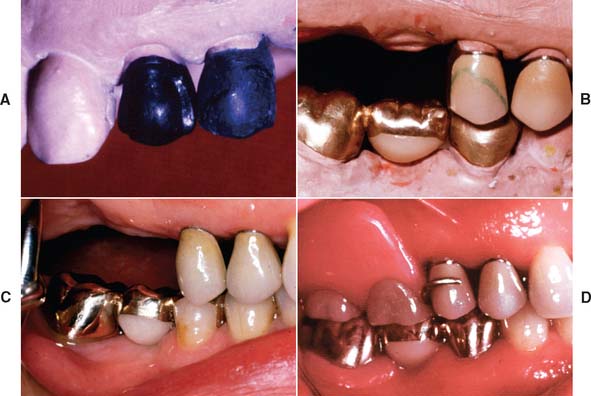
Fig. 21-22 A, A proximal guide plane and the correct axial survey lines are incorporated in the anatomic contour wax pattern. B, The contours are duplicated in porcelain. C, The fixed prostheses have been cemented. D, An accurately contoured retainer provides proper support for the partial removable dental prosthesis.
The minimum cervico-occlusal length for guide planes allows the reciprocal arms of the clasps to make initial contact and remain in contact during seating of the partial RDP (see Fig. 21-17).
Occlusal Rest Seats
Occlusal rest seats (Fig. 21-23) are most commonly located in the interproximal marginal ridge area and can easily be cut into the wax patterns with a hand-held round bur (see Fig. 21-21). When metal-ceramic restorations are the retainers, the rest seat should be located in metal at least 1 mm from the metal-ceramic junction (Fig. 21-24). When a rest is placed in a wax pattern for a metal-ceramic restoration, this is best done after the pattern has been cut back for the metal-ceramic veneer.
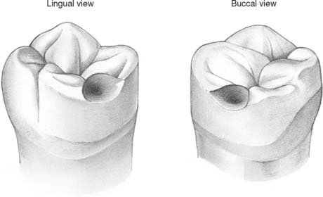
Fig. 21-23 Completed wax pattern for a partial removable dental prosthesis retainer with occlusal rest seat, distobuccal retention, and proximal and lingual guide planes.
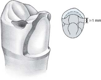
Fig. 21-24 Maxillary premolar wax pattern after cutting back for the porcelain application. The rest seat should be at least 1 mm from the metal-ceramic junction. The guide plane continues in the porcelain.
Cingulum rest seats (Fig. 21-25; see also Fig. 21-13) are placed with a carver. Buccolingually, they have a V configuration in cross-section; mesiodistally, they are slightly curved, with the highest point in the center of the tooth.
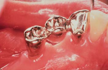
Fig. 21-25 Cingulum rest seat on a mandibular canine. Note its mesiodistal curvature (compare with Fig. 21-21I).
(Courtesy of Dr. X. Lepe.)
SPECIAL FINISHING PROCEDURES
After the wax patterns have been invested and eliminated and the retainers have been cast, the restoration is carefully seated on the die. When the individual fit is satisfactory, it is transferred on a tripodized cast to the surveyor for milling. The survey table is adjusted so the cast is oriented at the correct angulation, and cylindrical rotary instruments are used to refine the guide planes and to make any needed corrections.
Milling
Many precision parallel milling devices are available commercially. The simplest consists of a clamp that holds a conventional straight handpiece parallel to the shaft of the surveyor (Fig. 21-26). This works satisfactorily when used carefully. There are also expensive machine-tool milling devices that can be controlled with great precision and are particularly useful for extensive attachment prostheses (Fig. 21-27).
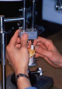
Fig. 21-26 Handpiece holder for milling guide planes. The holder attaches a conventional straight handpiece parallel to the shaft of a dental surveyor.
Cylindrical carbide burs without crosscuts are recommended for refining the proximal and reciprocal guide planes. Light pressure should be used throughout the milling procedure. Once an acceptable contour has been obtained, only minimum finishing with paper disks or rubber wheels is necessary. A complete- or partial-coverage crown is finished through the normal sequence of abrasives until a high polish has been attained. If the retainer is a metal-ceramic crown, the veneering surface is prepared after completion of the milling procedure. Then the desired survey line and retentive undercuts are established in porcelain. The porcelain can then either be glazed or polished while care is taken to maintain the desired heights of contour.
Caution is needed when survey lines are scribed on a bisque bake of porcelain. Red or green pigments must be used because they do not cause contamination after firing. Graphite from a soft lead pencil produces discoloration in the fired porcelain, and the use of such pencils must therefore be avoided (see Fig. 21-22B).
EVALUATION AND CEMENTATION
The clinical evaluation of the prosthesis proceeds as for any restoration. It should have good marginal integrity and proper axial contour, and it should be stable with accurate occlusal and proximal contact.
When these criteria have been met, a precementation irreversible hydrocolloid impression is poured in fast-setting stone, and the cast is analyzed on the surveyor. Any change in contour that may have occurred during finishing is easily detected at this time, when corrective action is still possible. For a metal-ceramic restoration, recontouring, repolishing, and/or reglazing may be necessary.
Cementation procedures for survey crowns are identical to those for conventional restorations (see Chapter 31). When multiple restorations involving prefabricated attachments are to be cemented, postponing cementation of the retainers until after the completion of the RDP is sometimes advantageous.
FABRICATION OF A CROWN FOR AN EXISTING PARTIAL RDP
Occasionally patients have a defective abutment crown under an otherwise satisfactory partial RDP. Although a new RDP is often the more appropriate choice, at least 14 different methods have been described for making a crown fit an existing partial RDP.8,9 These can be classified as direct, direct-indirect, or indirect procedures.
When a direct-indirect procedure is used, a pattern is fabricated from autopolymerizing acrylic resin and wax. The resin is applied onto the tooth preparation, and resin is added until it contacts the internal aspect of the RDP clasps, thus duplicating the axial contours of the original abutment crown. This resin pattern is repositioned on a die on which the margins are refined by adding wax and shaping the restoration. The combined resin-wax pattern is invested, and after wax and resin elimination, the crown is cast.
The indirect procedure consists of a “pickup” impression of the prepared tooth and seated partial RDP. This is poured in the conventional way after any undercuts in the denture have been waxed out. The crown is fabricated in the conventional way, the RDP being removed and replaced on the cast to establish appropriate contours. Additional wax (or porcelain for a metal-ceramic crown) is added where the retentive undercut is needed (Fig. 21-28). A disadvantage of this technique in comparison with the direct approach is that the partial RDP is required in the laboratory throughout the crown fabrication. This may not be acceptable to the patient, particularly if the patient’s appearance is affected.
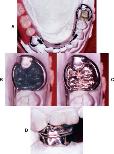
Fig. 21-28 Crown fabricated to fit an existing partial removable dental prosthesis (RDP) through the indirect procedure. A, After a pickup impression, the partial RDP is fitted to the definitive cast. B, Wax pattern. C and D, Completed crown.
(Courtesy of Dr. M. T. Padilla.)
With all these techniques, extra care is necessary in finishing the areas of the crown where contact with the RDP occurs. Small clasp adaptation imperfections often result, but with some practice, it is possible to routinely fabricate quite acceptable restorations that prevent the need to fabricate a new RDP.
ATTACHMENTS
A wide range of prefabricated attachments are available for use with partial RDPs.10,11 Most of these consist of two components: one is incorporated in the crown, and the other becomes part of the RDP. Both extracoronal and intracoronal designs are available (Fig 21-29).
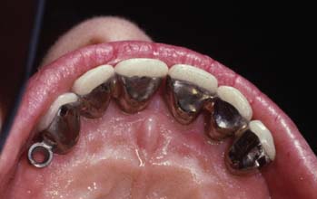
Fig. 21-29 An intracoronal and an extracoronal attachment were used in this anterior fixed dental prosthesis.
(Courtesy of Dr. F.-F. Hsu.)
In general, the use of attachments, whether extracoronal or intracoronal, should be limited. Attachments add to the complexity and cost of the restorative service and often necessitate remaking the fixed retainers when the attachments wear out. In one study, only 22 of 57 prostheses were free of complications during the first 2 years.12 When used with distal extensions, attachments lead to higher stresses in the abutment teeth.13 Nevertheless, their use can be justified, particularly to enhance appearance.
Extracoronal Attachments
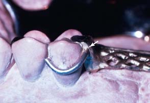
Any prefabricated attachment for support and retention of an RDP in which the “male” and “female” components are positioned outside the normal contour of the abutment tooth is considered an extracoronal attachment (Fig. 21-30). Careful judgment is needed in deciding when to use such attachments (e.g., ERA,* Ceka,† Dalbo,‡ or Dawson§) because they place unfavorable stresses on the abutment teeth, similar to the stresses exerted by a cantilever. In addition, they make oral hygiene more difficult. In some instances, however, extracoronal attachments offer esthetic advantages that may outweigh their biologic and mechanical disadvantages (Fig. 21-31). Resin bonding has been used for the retention of extracoronal attachments through the same principles as resin-bonded prostheses.14 It is doubtful that the retention obtained in that manner is adequate to prevent eventual dislodgment of the attachment.
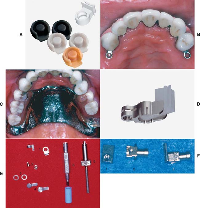
Fig. 21-30 Prefabricated extracoronal attachments. A, The ERA. These attachments are designed to be resilient and direct stress to both the abutment teeth and edentulous ridges when supporting distal extension partial removable dental prostheses (RDPs). The color-coded male components are processed directly into the acrylic denture base and have different levels of retention. B, Abutment crowns incorporating ERA attachments. C, Completed prostheses. D, The Dalbo Mini. This attachment provides some movement between male and female components. E, The Ceka: 1, female component; 2, male component; 3, spacer; 4, male partial RDP connector; 5, positioning mandrel; 6, adjustment tool. F, The 2.7 Dawson: 1, male component; 2, female component, which has a built-in replaceable plunger for retention; 3, the 2.7 Dawson attachment assembled.
(A and D, Courtesy of Sterngold Dental, LLC, Attleboro, Massachusetts; B, C, and F, courtesy of Dr. W. V. Campagni.)
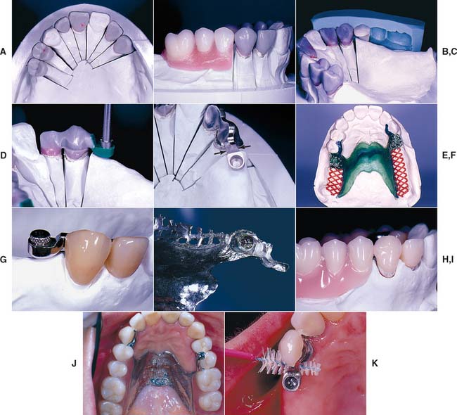
Fig. 21-31 Use of Ceka extracoronal attachments to retain a distal extension partial removable dental prosthesis (RDP). A and B, Anatomic contour waxing and occlusal plane development. C, A buccal index is used to allow repositioning of the denture teeth to help identify correct attachment placement. D, The female attachment pattern is positioned in relation to the wax pattern by means of a special mandrel in the dental surveyor. E, The substructures have been cast. Adequate strength is present where the extracoronal female attachment joins the retainer (arrows). F, Refractory cast with RDP wax pattern. G, Male component positioned in the female attachment. H, Attachment picked up. I, The completed prosthesis hides the attachment from sight. J, The RDP in place. K, Proxy brush enables appropriate plaque control around the attachment.
(Courtesy of Dr. Freijich and Mr. Behaeghel.)
Intracoronal Attachments
Intracoronal attachments have male and female components that are positioned within the normal contour of the abutment tooth. These can be prefabricated or made in the dental laboratory.
Prefabricated types
The more commonly used prefabricated intracoronal attachments (e.g., Stern* or Ney-Cheyes No. 9†) typically consist of a precision-milled male-female assembly (Fig. 21-32) similar to the dovetail configuration described for nonrigid connectors (see Chapter 28).
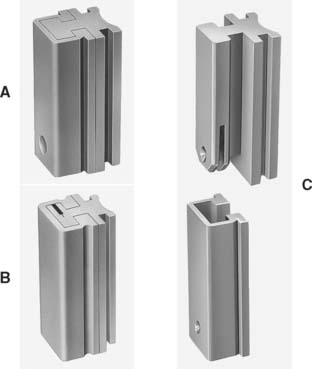
Fig. 21-32 Prefabricated intracoronal attachments. A and B, The Stern Latch (see Fig. 21-33). C, The C&M McCollum.
(A to C, Courtesy of Sterngold Dental, LLC, Attleboro, Massachusetts.)
The tolerance between accurately fitting components of an intracoronal precision attachment is so fine that retention results from their frictional fit. An intracoronal precision attachment partial RDP is not readily dislodged, because it can be removed only in one direction, which may become a liability in patients with limited dexterity. However, retention can be significantly reduced after wear of the retentive surfaces. Most precision attachments are made of platinum-palladium alloys, which withstand the high temperature associated with casting of metal-ceramic alloys.
The female attachment is incorporated in the retainer wax pattern, and the assembly is invested. After wax elimination, the restoration is cast directly onto the attachment. Although multiple parallel attachments can be fabricated in this manner, most technicians prefer to solder a second or third attachment to the respective retainers. This allows for verification of alignment with the attachment in the first retainer.
A tray may be incorporated in the secondary retainer for added flexibility during positioning of the second attachment parallel to the first attachment. The secondary retainer is luted into place, invested, and soldered. Male components can then be inserted. After the partial RDP framework has been made, the male attachments are either soldered to the frame or attached to the acrylic resin denture base with autopolymerizing resin (Figs. 21-33 and 21-34).
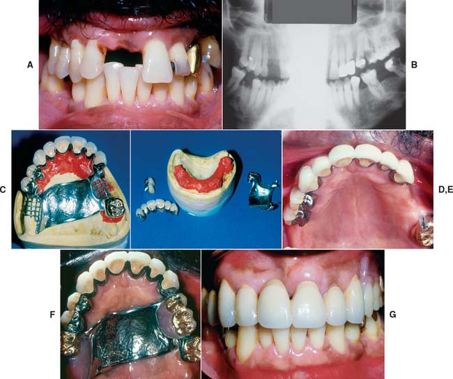
Fig. 21-33 Use of Stern Latch intracoronal attachments to support and retain a maxillary partial removable dental prosthesis (RDP). The Stern Latch attachment has frictional retention augmented by an internal gingival spring latch. The matrix may be waxed and cast-to. The male may be soldered to the framework or embedded in the resin of the finished partial RDP. A and B, This patient had extensive periodontal disease and caries, which necessitated the loss of several teeth with a hopeless prognosis. C, The resin-reinforced definitive cast with the finished fixed prostheses and partial RDP framework. D, Restorations and framework removed from the cast. E, Cemented fixed restorations without the partial RDP. F, Intraoral view of finished prostheses. G, Anterior, intraoral view of finished treatment.
(Courtesy of Dr. W. V. Campagni.)
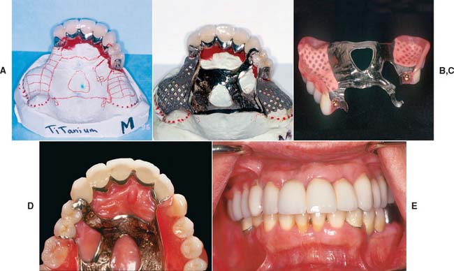
Fig. 21-34 Use of the Dawson 2.7 extracoronal attachment to support and retain a maxillary partial removable dental prosthesis (RDP). This precision attachment comprises an extracoronal patrix, which is waxed into the fixed abutment prosthesis and cast-to. The matrix comprises a housing with a spring-loaded plunger for retention. The plunger engages a dimple on the distal of the patrix. The plunger and spring can be removed from the housing for replacement with a special U-shaped pin. A, Definitive cast with finished crowns on resin replica dies for fabrication of partial RDP framework. B, Framework on definitive cast. Matrix will be luted to frame with resin for try-in. C, View of finished partial RDP, showing matrix processed in place. D, Occlusal view of partial RDP intraorally. E, Anterior view of finished treatment.
(Courtesy of Dr. W. V. Campagni.)
The preceding paragraph condenses an intricate sequence of technically highly demanding steps. The less experienced operator is strongly cautioned not to underestimate the high level of skill and meticulous attention to detail that are required.
The biggest advantage of intracoronal attachments is that they eliminate the need for an often unesthetic facial clasp. Simultaneously, however, the size of most intracoronal precision attachments limits their application, especially on vital teeth. To facilitate maintaining the health of supporting tissues, the proximal surface of the restor-ation should not be overcontoured. Therefore, the optimum placement of attachments is within the normal contours of the tooth and thus the restoration. However, this is usually possible only on large teeth. On small teeth, few intracoronal precision attachments can be kept within the confines of normal tooth contour without endodontic treatment. In addition, sufficient clinical crown height must exist for adequate cervico-occlusal length to allow a positive friction fit (a minimum attachment height of 4 mm or more is recommended).
Laboratory-made types
Many laboratory-made (semiprecision) attachments are in use today. Often they are referred to as dovetails because of the shape of their interlocking components. They can be made by incorporating a prefabricated plastic insert in the wax pattern, which is then invested and eliminated, and the pattern is cast (Fig. 21-35). The female dovetail can also be milled, after which the male component is waxed and cast.
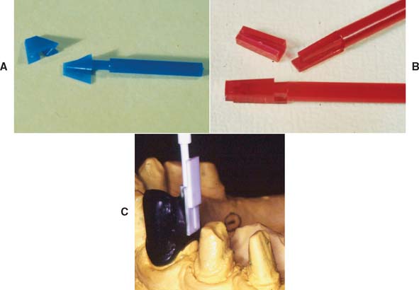
Fig. 21-35 A to C, Plastic preformed patterns for an intracoronal rest.
(C, Courtesy of Dr. F.-F. Hsu.)
An alternative method of fabrication is to use a tapered metal mandrel (e.g., Ticon*) that is heated and inserted in the wax pattern. When the wax is eliminated after investing, the exposed portion of the mandrel in the mold oxidizes. The crown is then cast directly onto the mandrel, which is later removed (Fig. 21-35). A male attachment can be waxed and cast separately. After seating, the attachment is soldered to the partial RDP.
Because of the inaccuracies inherent in their fabrication, most laboratory-made attachments have a limited amount of frictional retention in comparison with the commercially available precision attachments. The majority are tapered for ease of fabrication and therefore require the use of lingual clasps for positive retention.
When attachments are used with a metal-ceramic restoration, adequate metal must remain between the female component and the facial veneer of dental porcelain. A minimum material thickness of 1 mm is recommended between any intracoronal attachment and the metal-ceramic interface (Fig. 21-36).
Bars, Studs, and Magnets
Stud attachments15 and magnets16 (Fig. 21-37) are sometimes used to retain overdentures. They are incorporated in post-retained castings or implant abutments and offer the advantage of allowing increased occlusal force17 (Fig. 21-38). In order to have adequate room for all attachment components, the denture resin, and a hollowed-out shell of a denture tooth (see Fig. 21-38B), a minimal vertical space of 7 to 9 mm is recommended, to enable successful use of these types of attachments.
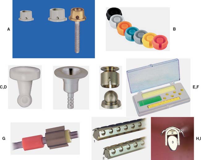
Fig. 21-37 A and B, The ERA stud attachment. Like the ERA extracoronal attachment (see Fig. 21-30A to C), this resilient attachment is available in different sizes (Stern ERA and Micro ERA) and color-coded retention levels. C and D, The Stern Root Anchor. This stud attachment comprises an intraradicular ball-and-socket joint. The nylon male (C) is processed into the denture acrylic. The titanium female (D) is cemented directly into the prepared root. E, The Dalla Bona Spherical. A gold alloy stud attachment with adjustable frictional resistance. F and G, The Hader bar. This bar system uses a plastic bar that is incorporated into the fixed prostheses before casting. Color-coded nylon rider clips are incorporated into the denture and are available with varying retention. Alternatively, a gold rider can be used for greater strength. H, The Dolder bar. This gold alloy bar is available in rigid (1) and resilient or hinging (2) configurations. I, 1, Sleeve; 2, spacer; 3, bar.
(A to H, Courtesy of Sterngold Dental, LLC, Attleboro, Massachusetts.)
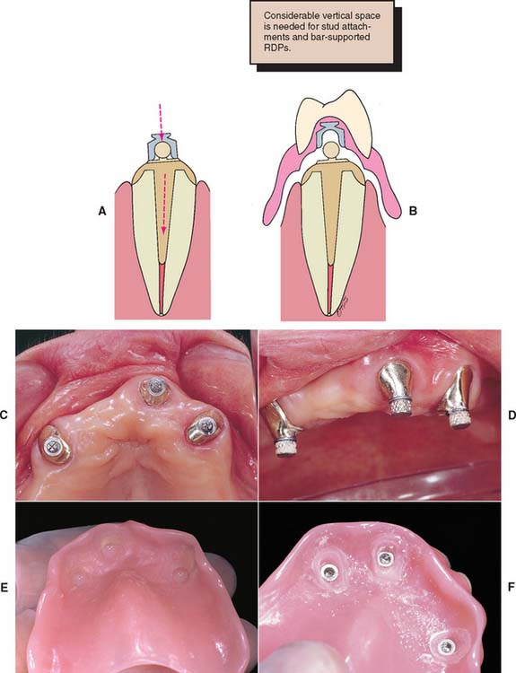
Fig. 21-38 A, Illustration of post-retained casting incorporating the male component of a stud attachment. The design allows for slightly different paths of insertion (arrows) of the post and overdenture. B, The female component is attached to the overdenture with acrylic resin. RDP, removable dental prosthesis. C, Occlusal view of three cemented copings with the male components in place. D, Female attachments have been positioned over the male attachments. E, Resin is applied to the internal surface of the prosthesis immediately before the denture is inserted. F, Denture immediately after relief of excess resin around the female components, which are now mechanically retained in the prosthesis.
(Courtesy of Dr. Freijich and Mr. Behaeghel.)
A bar-retained partial RDP or overdenture can be very stable while it braces individual abutment teeth. The bar should attach to the retainer without interfering with oral hygiene.
In general, this means that considerable coronal length is necessary for the bar to produce an acceptable result. The bar should not be placed in contact with an edentulous ridge (Fig. 21-39).
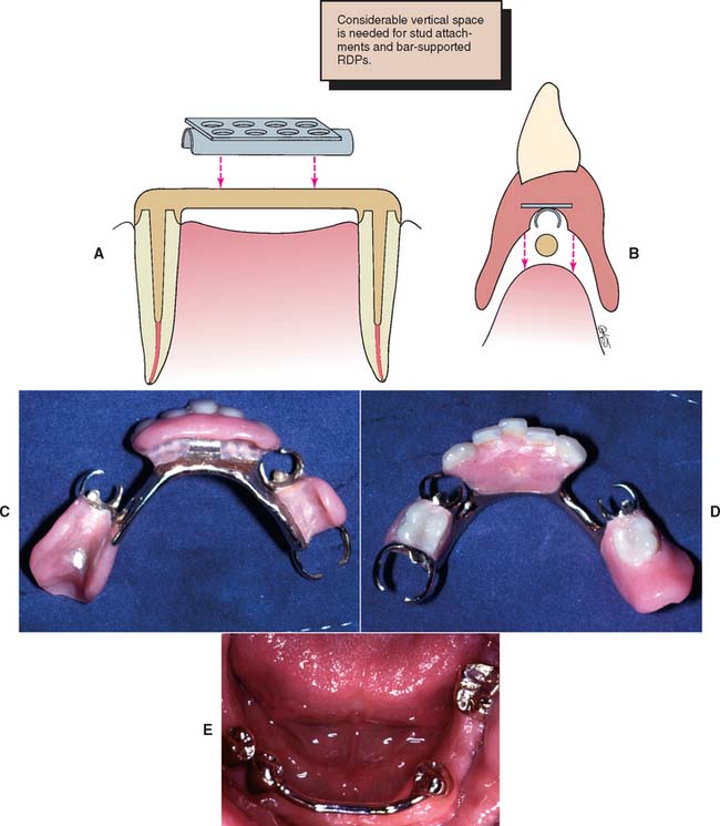
Fig. 21-39 Bar attachment. A, The bar is retained by posts on conventional fixed restorations. The clip provides support and retention for the partial removable dental prosthesis (RDP). B, Sufficient incisogingival height is needed to accommodate a bar prosthesis. C, Internal view of the bar-retained partial RDP. D, Occlusal view. E, Cemented fixed prosthesis with a bar to accommodate an RDP.
SUMMARY
Along with conventional diagnostic procedures, an in-depth survey analysis of the diagnostic cast must be performed for any patient who requires a partial RDP. The coronal surfaces of the abutment teeth should be shaped to allow for optimum retention and stability of the RDP during function. Simultaneously, proximal and reciprocal guide planes should be established to guide and stabilize the prosthesis during placement and to minimize horizontal forces on the abutment teeth.
To achieve harmony with the necessary RDP design, making cast restorations on otherwise intact and caries-free teeth is sometimes necessary. Unaltered crowns of natural teeth may not have suitable contours or axial configuration for the best clasp design.
The amount of tooth reduction needed to fabricate restorations with the desired survey contours is often slightly greater than that needed if the respective abutment teeth are prepared for conventional restorations. Allowances must be made for occlusal rest seats and guide planes. Precision and semiprecision attachments can offer esthetic and retentive advantages (Fig. 21-40).
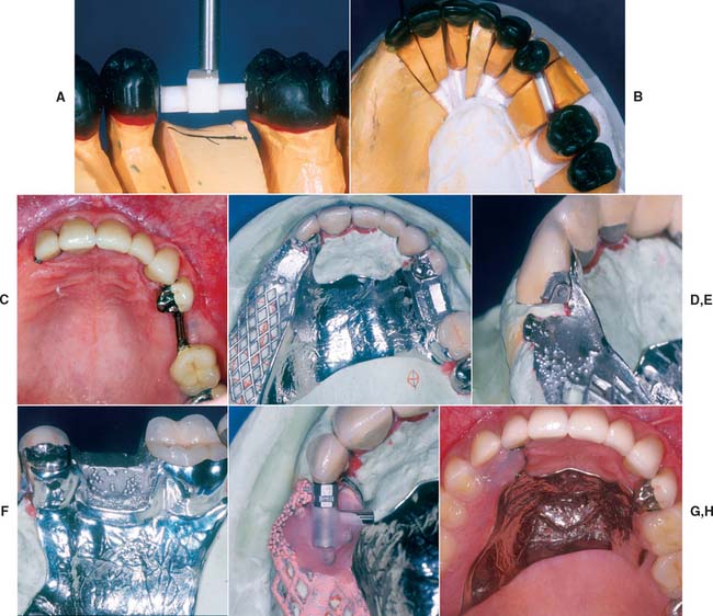
Fig. 21-40 Use of a combination of bar and extracoronal attachments for support and retention of a maxillary partial removable dental prosthesis (RDP) according to the rotational path concept. The COMPAS attachment system was chosen as the extracoronal attachment. This system was designed by Dr. Peter Dawson and is an evolution of the D 2.7 attachment (see Fig. 21-34), which was also designed by Dr. Dawson. It includes preformed plastic parts that are placed by mandrels and waxed into the crown forms for cut-back and casting. It also includes a spring-loaded plunger that is incorporated into the matrix, which is luted to the partial RDP framework by embedding into the resin. Preformed plastic bar and matrix forms were used and were incorporated into the fixed prostheses wax patterns. A, Curved bar is positioned and waxed to place. B, Anatomic contour waxing with bar on left and extracoronal attachment on right abutment. C, Completed crowns evaluated. The fixed restorations were picked up in an impression that was used to fabricate the definitive cast for the RDP framework. D, Framework and restorations on definitive cast. E, Attachment on distal side of abutment. F, Framework cast to fit over curved bar. G, Plunger assembly luted to framework for evaluation. H, Intraoral view of completed prostheses.
(Courtesy of Drs. W. V. Campagni and F. Munguia.)
Intracoronal attachments are often more esthetic than conventional clasps. They work well if kept within the normal contours of the teeth.
Extracoronal attachments should be used sparingly because of their unfavorable loading of abutment teeth and the associated problems in maintaining oral hygiene.
Attachments and occlusal rest seats in metal-ceramic restorations should be placed at least 1 mm from the metal-ceramic interface.
Survey crowns require finishing procedures for which special milling equipment is needed.
A precementation impression should be obtained for verifying that the best coronal contours have been created in harmony with the partial RDP.
 GLOSSARY*
Akers clasp \Ā′kerz klăsp\ [Polk E. Akers, Chicago, III, dentist]: eponym for a one piece cast partial denture with cast clasps. He is said to have improved and standardized the one piece casting method for fabricating gold partial dentures in the early 1920s—see SUPRABULGE CLASP
Akers PE Partial dentures. J Amer Dent Assoc 1928;15:717–22.
angle of gingival convergence \ăng′gl ŭv j n′ji-val, -jn-jī′- kun-vûr′jens\ 1: according to Schneider, the angle of gingival convergence is located apical to the height of contour on the abutment tooth. It can be identified by viewing the angle formed by the tooth surface gingival to the survey line and the analyzing rod or undercut gauge in a surveyor as it contacts the height of contour 2: the angle formed by any surface of the tooth below the survey line of the height of contour, with the selected path of insertion of a prosthesis 3: the angle formed by the tooth surface below the height of contour with the vertical plane, when the occlusal surface of the tooth is oriented parallel to the horizontal plane
Schneider RL. J Prosthet Dent 1987;58:194–6.
attachment \a-tăch′ment\ n (15c) 1: a mechanical device for the fixation, retention, and stabilization of a prosthesis 2: a retainer consisting of a metal receptacle and a closely fitting part; the former (the female [matrix] component) is usually contained within the normal or expanded contours of the crown of the abutment tooth and the latter (the male [patrix] component) is attached to a pontic or the denture framework—see FRICTIONAL A., INTERNAL A., KEY and KEYWAY A., PARALLEL A., PRECISION A., RESILIENT A., SLOTTED A.
bar clasp \bär klăsp\: a clasp retainer whose body extends from a major connector or denture base, passing adjacent to the soft tissues and approaching the tooth from a gingivo-occlusal direction
3base \bās\ n (19c): the portion of a denture that supports the artificial dentition and replaces the alveolar structures and gingival tissues—see DENTURE B.
buccal vestibule \bŭk′al v s′ti-byōōl\: the portion of the oral cavity that is bounded on one side by the teeth, gingiva, and alveolar ridge (in the edentulous mouth, the residual ridge) and on the lateral side by the cheek posterior to the buccal frenula
cingulum rest \sng′gya-lum rst\: a portion of a removable dental prosthesis that contacts the prepared or natural cingulum of the tooth, termed the cingulum rest seat
clasp \klăsp\ n (14c): the component of the clasp assembly that engages a portion of the tooth surface and either enters an undercut for retention or remains entirely above the height of contour to act as a reciprocating element. Generally it is used to stabilize and retain a removable dental prosthesis—see BAR C., CIRCUMFER-ENTIAL C., COMBINATION C., CONTINUOUS C.
clasp assembly \klăsp a-sěm′blē\: the part of a removable partial denture that acts as a direct retainer and/or stabilizer for a prosthesis by partially encompassing or contacting an abutment tooth—usage: components of the clasp assembly include the clasp, the reciprocal clasp, the cingulum, incisal or occlusal rest, and the minor connector
clip \klp\ n (15c) slang 1: any of numerous devices used to grip, clasp, or hook 2: a device used to retain a removable prosthesis intraorally to a fixed abutment; i.e., a bar, crown, or other retainer
cor·rode \ka-rōd\ vt (15c) 1: deterioration of a metal due to an electrochemical reaction within its environment 2: to eat away by degrees as if by gnawing 3: to wear away gradually usually by chemical action
cor·ro·sion \ka-rō′zhen\ n (15c): the action, process, or effect of corroding; a product of corroding; the loss of elemental constituents to the adjacent environment
direct retainer \d-rěkt, dī- r-tā′ner\: that component of a partial removable dental prosthesis used to retain and prevent dislodgment, consisting of a clasp assembly or precision attachment
Dolder bar [Eugene J. Dolder, Zurich, Switzerland prosthodontist]: eponym for one of many bar attachments that splint teeth or roots together while acting as an abutment for a partial removable dental prosthesis. The bar is straight with parallel sides and a round top. The sleeve or clip that fits over the bar gains retention by friction only. The bar may be of variable size and is pear shaped in cross section, as is its accompanying sleeve. This clip allows for some measure of rotational movement about the bar
Dolder EJ. The bar joint mandibular denture. J PROSTHET DENT 1961;11:689–707.
dove·tail \dŭv′tāl′\ n (1565): a widened portion of a prepared cavity used to increase retention and/or resistance
fulcrum line \f l′krum līn\ 1: a theoretical line passing through the point around which a lever functions and at right angles to its path of movement 2: an imaginary line, connecting occlusal rests, around which a partial removable dental prosthesis tends to rotate under masticatory forces. The determinants for the fulcrum line are usually the cross arch occlusal rests located adjacent to the tissue borne components—see F.L. OF A REMOVABLE PARTIAL DENTURE, RETENTIVE F.L.
guiding planes \gī′dng plānz\: vertically parallel surfaces on abutment teeth or/and dental implant abutments oriented so as to contribute to the direction of the path of placement and removal of a removable partial denture
Hader bar [after the Swiss tool and die technician, Helmut Hader]: eponym for a rigid bar connecting two or more abutments, which, when viewed in cross section, resembles a keyhole, consisting of a rectangular bar with a rounded superior (occlusal) ridge that creates a retentive undercut for the female clip within the removable prosthesis
Breim SL., Renner RP. An overview of tissue bars. Gen Dent 1982: 406–15.
height of contour \hīt ŭv kn′t
r′\: a line encircling a tooth and designating its greatest circumference at a selected axial position determined by a dental surveyor; a line encircling a body designating its greatest circumference in a specified plane
indirect retention \n′d-rěkt′, -dī- r-těn′shun\: the effect achieved by one or more indirect retainers of a partial removable denture that reduces the tendency for a denture base to move in an occlusal direction or rotate about the fulcrum line
infrabulge clasp \n′fra-bŭlj klăsp\: a removable partial denture retentive clasp that approaches the retentive undercut from a cervical or infrabulge direction
internal attachment: see PRECISION ATTACHMENT
keep·er \kē′par\ n (14c): any one of various devices used for keeping something in position—usage: in dentistry, this is usually construed to mean a magnetized alloy attached to one element of a restoration to which a magnet may adhere
Kennedy classification of removable partial dentures [Edward Kennedy, U.S. dental surgeon, variably dated 1923, 1925, and 1928]: a classification of partially edentulous arches divisible into four classes. Class 1: a bilateral edentulous areas located posterior to the remaining natural teeth. Class II: a unilateral edentulous area located posterior to the remaining natural teeth. Class III: a unilateral edentulous area with natural teeth located both anterior and posterior to it. Class IV: a single bilateral edentulous area located anterior to the remaining natural teeth. Edentulous areas, in addition to those determining the main types, were designated as modification spaces. O. C. Applegate’s Rules govern application of the Kennedy system
Kennedy E. Partial denture construction. Brooklyn: Dental Items of Interest, 1928.
key·way \kē′wā′\ n: an interlock using a matrix and patrix between the units of a fixed dental prosthesis. It may serve two functions: 1) to hold the pontic in the proper relationship to the edentulous ridge and the opposing teeth during occlusal adjustment on the working cast (during application of any veneering material) and 2) to reinforce the connector after soldering
labial vestibule \lā′bē-al věs′ta-byōōl\: the portion of the oral cavity that is bounded on one side by the teeth, gingiva, and alveolar ridge (in the edentulous mouth, the residual ridge) and on the other by the lips anterior to the buccal frenula
lingual plate \lng′gwal plāt\: the portion of the major connector of a removable partial denture contacting the lingual surfaces of the natural teeth—also spelled linguoplate
lingual rest seat \lng′gwal rěst sēt\: the depression prepared on the lingual surface of an abutment tooth to accept the metal rest of a partial denture (the lingual rest)
mill in \ml n\ v 1: the procedure of refining occluding surfaces through the use of abrasive materials—see SELECTIVE GRINDING 2: the machining of boxes or other forms in cast restorations to be used as retainers for fixed or removable prostheses
mill·ing \ml′ng\ v: the machining of proximal boxes, recesses, or other forms on cast restorations to be used as retainers for fixed or removable prostheses
minor connector \mī′nar ka-něk′tor\: the connecting link between the major connector or base of a removable dental prosthesis and the other units of the prosthesis, such as the clasp assembly, indirect retainers, occlusal rests, or cingulum rests
occlusal rest \a-klōō′zal, -sal rěst\: a rigid extension of a partial removable dental prosthesis that contacts the occlusal surface of a tooth or restoration, the occlusal surface of which may have been prepared to receive it—see REST SEAT
o·ver·clo·sure \ō′var-klō′zhar\ n: an occluding vertical dimension at a reduced interarch distance; an occluding vertical dimension that results in excessive interocclusal distance when the mandible is in the rest position; it results in a reduced interridge distance when the teeth are in contact
parallel attachment: see PRECISION ATTACHMENT
partial denture \pär′shal děn′chur\: a removable dental prosthesis or a fixed dental prosthesis that restores one or more but not all of the natural teeth and/or associated parts and may be supported in part or whole by natural teeth, dental implant supported crowns, dental implant abutment(s), or other fixed dental prostheses and/or the oral mucosa; usage: a partial denture can be described as a fixed dental prosthesis or removable dental prosthesis based on the patient’s capability to remove or not remove the prosthesis. If the prosthesis is a fixed dental prosthesis that can only be removed by a clinician, i.e., a fixed dental prosthesis (FDP) supported by dental implants that has been retained by means of a mechanical system [i.e., screw(s)], this prosthesis is also termed a fixed dental prosthesis. Adjectives (modifiers) may be added to the clinical description of the dental prosthesis, if needed, to designate the means of mechanical retention, i.e., a screw retained fixed dental prosthesis. Any such prosthesis luted to dental implants (in the same manner as luting a fixed dental prosthesis to natural teeth) needs no additional designation as to its means of retention—see BILATERAL DISTAL EXTENSION REMOVABLE D.P., FIXED D.P., REMOVABLE D.P., UNILATERAL REMOVABLE D.P.
partial denture rest \pär′shal děn′chur rěst\: a rigid extension of a fixed or removable partial denture that prevents movement toward the mucosa and transmits functional forces to the teeth
partial denture retention \pär′shal děn′chur r-těn′shun\: the ability of a removable dental prosthesis to resist movement away from its foundation area and/or abutments
pas·sive \păs′v\ adj (14c): 1: not active or in operation; inert; latent 2: resistant to corrosion 3: existing or occurring without being active, direct, or open
precision attachment \pr-szh′un a-tăch′mant\ 1: a retainer consisting of a metal receptacle (matrix) and a closely fitting part (patrix); the matrix is usually contained within the normal or expanded contours of the crown on the abutment tooth/dental implant and the patrix is attached to a pontic or the removable partial denture prosthesis framework 2: an interlocking device, one component of which is fixed to an abutment or abutments, and the other is integrated into a removable prosthesis in order to stabilize and/or retain it
re·cip·ro·cal \r-sp′ra-kal\ adj, obs: the manner in which one part of a prosthesis is made to counter the effect created by another part (GPT-1)
reciprocal arm: see RECIPROCAL CLASP
reciprocal clasp \r-sp′ra-kal klăsp\: a component of the clasp assembly specifically designed to provide reciprocation by engaging a reciprocal guiding plane; it contacts the action of the clasp during removal and insertion of a removable partial denture
re·cip·ro·ca·tion \r-sp′ra-kā′shun\ n (1561) 1: the mechanism by which lateral forces generated by a retentive clasp passing over a height of contour are counterbalanced by a reciprocal clasp passing along a reciprocal guiding plane 2: a mutual exchange 3: an alternating motion—re·cip·ro·ca·tive \r-sp′ra-kā′tv\ adj
resilient attachment \r-zl′yant a-tăch′mant\ (1998): an attachment designed to give a tooth borne/soft tissue borne removable dental prosthesis sufficient mechanical flexion to withstand the variations in seating of the prosthesis due to deformations of the mucosa and underlying tissues without placing excessive stress on the abutments
rest seat \rěst sēt\: the prepared recess in a tooth or restoration created to receive the occlusal, incisal, cingulum, or lingual rest
retentive clasp \r-těn′tv klăsp\ 1: a clasp specifically designed to provide retention by engaging an undercut 2: a flexible segment of a partial removable dental prosthesis that engages an undercut on an abutment and that is designed to retain the prosthesis
RPD: acronym for Removable Partial Denture (now termed a Removable Dental Prosthesis)
RPI: acronym for Rest, Proximal Plate, and I-BAR; the clasp components of one type of removable partial denture clasp assembly
semiprecision rest \sěm′ē-pr-szh′an rěst\: a rigid metallic extension of a fixed or removable dental prosthesis that fits into an intracoronal preparation in a cast restoration
stress director \strěs d-rěk′tar, dī-\: a device or system that relieves specific dental structures of part or all of the occlusal forces and redirects those forces to other bearing structures or regions
su·pra·bulge \sōō′pra-bŭlj\ adj: that portion of a tooth crown that converges toward the occlusal surface, i.e., above the height of contour
suprabulge clasp \sōō′pra-bŭlj klăsp\: a removable partial denture retentive clasp that approaches the retentive undercut from an occlusal or suprabulge direction
survey line \sûr′vā′ līn\: a line produced on a cast by a surveyor marking the greatest prominence of contour in relation to the planned path of placement of a restoration
sur·vey·or \sur-vā′or\ n (15c): a paralleling instrument used in construction of a prosthesis to locate and delineate the contours and relative positions of abutment teeth and associated structures
tooth-supported base \tōōth-sa-pôr′td bās\: a dental prosthesis base that restores an edentulous region that has abutment teeth at each end for support. The tissue that it covers is not used for support
tripod marking \trg′ur mär′kng\: those marks or lines drawn on a cast in a single plane perpendicular to the survey rod to assist with repositioning the cast on a dental surveyor in a previously defined orientation
1un·der·cut \ŭn′dur-kŭt\ n (1859) 1: the portion of the surface of an object that is below the height of contour in relationship to the path of placement 2: the contour of a cross-sectional portion of a residual ridge or dental arch that prevents the insertion of a dental prosthesis 3: any irregularity in the wall of a prepared tooth that prevents the withdrawal or seating of a wax pattern or casting
2un·der·cut \ŭn′dur-kŭt\ v (ca. 1598): to create areas that provide mechanical retention for materials placement
wrought \rôt\ adj (13c) 1: worked into shape; formed 2: worked into shape by tools; hammered
STUDY QUESTIONS
1 Altay OT, et al. Abutment teeth with extracoronal attachments: the effects of splinting on tooth movement. Int J Prosthodont. 1990;3:441.
2 Krol AJ, Finzen FC. Rotational path removable partial dentures. II. Replacement of anterior teeth. Int J Prosthodont. 1988;1:135.
3 Jones RM, et al. Dentin exposure and decay incidence when removable partial denture rest seats are prepared in tooth structure. Int J Prosthodont. 1992;5:227.
4 Seto BG, et al. Resin bonded etched cast cingulum rest retainers for removable partial dentures. Quintessence Int. 1985;16:757.
5 Dixon DL, et al. Use of a partial coverage porcelain laminate to enhance clasp retention. J Prosthet Dent. 1990;63:55.
6 Davenport JC, et al. Clasp retention and composites: an abrasion study. J Dent. 1990;18:198.
7 Berg T. I-bar: myth and countermyth. Dent Clin North Am. 1984;28:371.
8 Tran CD, et al. A review of techniques of crown fabrication for existing removable partial dentures. J Prosthet Dent. 1986;55:671.
9 Elledge DA, Schorr BL. A provisional and new crown to fit into a clasp of an existing removable partial denture. J Prosthet Dent. 1990;63:541.
10 Becerra G, MacEntee M. A classification of precision attachments. J Prosthet Dent. 1987;58:322.
11 Burns DR, Ward JE. Review of attachments for removable partial denture design. I. Classification and selection. Int J Prosthodont. 1990;3:98.
12 Owall B, Jonsson L. Precision attachment-retained removable partial dentures. III. General practitioner results up to 2 years. Int J Prosthodont. 1998;11:574.
13 Chou TM, et al. Photoelastic analysis and comparison of force-transmission characteristics of intracoronal attachments with clasp distal-extension removable partial dentures. J Prosthet Dent. 1989;62:313.
14 Doherty NM. In vitro evaluation of resin-retained extracoronal precision attachments. Int J Prosthodont. 1991;4:63.
15 Mensor MC. Removable partial overdentures with mechanical (precision) attachments. Dent Clin North Am. 1990;34:669.
16 Gillings BR, Samant A. Overdentures with magnetic attachments. Dent Clin North Am. 1990;34:683.
17 Sposetti VJ, et al. Bite force and muscle activity in overdenture wearers before and after attachment placement. J Prosthet Dent. 1986;55:265.
18 Akers PE. Partial dentures. J Am Dent Assoc. 1928;15:717.
19 Schneider RL. Significance of abutment tooth angle of gingival convergence on removable partial denture retention. J Prosthet Dent. 1987;58:194.
20 Dolder EJ. The bar joint mandibular denture. J Prosthet Dent. 1961;11:689.
21 Ladenheim SL, Renner RP. An overview of tissue bars. Gen Dent. 1982;30:406.
22 Kennedy E. Partial Denture Construction. Brooklyn, NY: Dental Items of Interest, 1928.