CHAPTER 24 Hand-Activated Instruments
BASIC INSTRUMENT DESIGN
Assessment and Treatment Instruments
Categories of instruments used in caring for clients with healthy or diseased periodontium are as follows:
 Assessment instruments provide the dental hygienist with clinical periodontal and tooth assessment information. Most dental hygiene treatment instruments are used to perform periodontal scaling and root planing (Tables 24-1 and 24-2). Therefore, use of these hand instruments is the focus of this chapter. (See Chapter 25 for ultrasonic instrumentation, Chapter 27 for coronal polishing instrumentation, and Chapter 36 for hand instruments used in restorative therapy.)
TABLE 24-1 Assessment Instruments
| Assessment Instruments | Basic Use |
|---|---|
| Mouth mirror | Indirect vision, indirect illumination, transillumination, and retraction of buccal mucosa and tongue; for use throughout appointment. |
 |
|
| Periodontal probe | Measurement of probing depth, clinical attachment level, relative attachment level, amount of attached gingiva, gingival recession, and furcation invasion; assessment of oral biofilm, gingival inflammation, bleeding points, and pathologic lesions. Used during assessment and again during the evaluation phase of care. |
 |
|
| Nabers probe | A furcation classification instrument to be used during assessment and again during the evaluation phase of care. |
 |
|
| Explorer | Detection of calculus, irregular cementum, junctional epithelium, dental caries, irregular root anatomy, margins or restorations, external resorption, and osseous exposures. For use during assessment, implementation, and evaluation phases of care. |
 |
TABLE 24-2 Treatment Instruments
| Treatment Instruments | Basic Use |
|---|---|
| Universal curet | |
 |
|
| Gracey curets | Area-specific curets that, depending on design, may be used in various areas of the mouth for supragingival and subgingival scaling, root planing, and oral biofilm removal. Used for periodontal scaling and root planing. |
 |
|
| Sickle | Principally a supragingival calculus removal instrument. Used for gross calculus removal. This instrument is not used for root planing. |
 |
|
| File | Used for supragingival and subgingival calculus removal where tissue is retractable. For use during initial scaling; should not be used for root planing. |
 |
|
| Hoe | Used for supragingival and subgingival calculus removal where tissue is retractable and during initial scaling; should not be used for root planing. |
 |
|
| Plastic and graphite instruments | Used for assessment as well as calculus and biofilm removal around titanium dental implant abutment cylinders; gold instruments are also used. |
 |
|
| Ultrasonic and sonic scaling devices (see Chapters 25 and 57) | Used for supragingival and subgingival calculus removal, oral biofilm recommendations regarding titanium dental implant abutment cylinders, unless working end is a specially designed rubber-coated tip (see Table 24-10 and Chapter 57, Figure 57-67). |
| Low-speed dental handpiece (see Chapter 27, Figure 27-2) | Used for oral biofilm and extrinsic stain removal after scaling and root planing are complete. Recommended for use with a fine abrasive agent for polishing titanium dental implant abutment cylinders The prophylaxis angle, rubber cup, point or brush, and polishing agent are part of the armamentarium. |
| Air polishing or airbrasion system (see Chapter 27Figure 27-18Figure 27-19Figure 27-20) | Used for oral biofilm and stain removal after scaling and root planing are complete. Contraindicated for use around titanium dental implant abutment cylinders. |
Examples of assessment and treatment instruments are shown in Figure 24-1. These instruments consist of three functional parts:
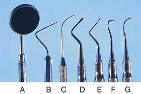
Figure 24-1 Assessment instruments: mirror (A), periodontal probe (B), explorer (C). Treatment instruments: file (D), hoe (E), sickle (F), curet (G).
Variations in these functional parts determine the purpose, effectiveness, efficiency, and comfort of use for the operator. A good assessment or treatment instrument supports all of these functions.
Parts and Characteristics of Dental Hygiene Instruments
Handle
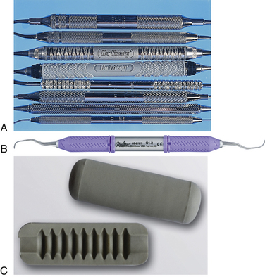
When an instrument is selected, handle specifications primarily benefit operator comfort. Nevertheless, handles should not be considered less important than any other part of the instrument. In response to a heightened concern for operator comfort and to lessen the effect of repetitive strain injuries (RSIs), instrument manufacturers offer a variety of handle options relating to material, size, and weight. The larger-diameter grips and new resin and silicone materials are more comfortable than the smaller metal handles. For example, the Big Easy Ultralite by Premier has a polymer handle with a medical grade silicone cushion grip; the Flexichange raised-dot handle by DENTSPLY uses a medical grade silicone and is ergonomically wider near the working ends and narrower near the middle; and the GripLite handle by Miltex combines hollow metal with a silicone grip). Because of the extra circumference of larger diameter grips, posterior access may be more difficult, especially if the client has limited mouth-opening ability. Slender handles can lead to cramping of the hands after prolonged use.
Handle shape or circumference may be round or hexagonal. Both are quite comfortable when a suitable surface pattern and material are used. The depth of the pattern cut into the handle or the relief on some handles may affect the practitioner’s comfort level. Some patterns are cut so deeply that they feel as if they are biting into the skin when pressure is placed on the instrument.
Handle weight is the final consideration in handle selection. There are solid-handled and hollow-handled instruments (e.g., the Big Easy Hollow Handle by Premier is stainless steel covered with silicone). Most clinicians find that hollow handles are lighter and less strenuous to use and allow greater tactile sensitivity than solid-handled instruments. Grips can also be added to instruments to improve comfort (Figure 24-2).
Shank
The shank of an instrument connects the working end to the handle and is the major factor determining the use of each particular instrument. Differences among instruments in shank design relate to the following:
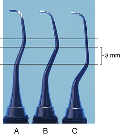
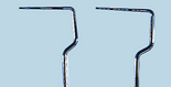
Length of Shank
Instrument shank length ranges from short to long (Figure 24-3). An instrument with a long shank is preferred for use on anterior or posterior teeth with deep periodontal pocket depths or recession, or when the operator needs to fulcrum a great distance from the area being instrumented. An instrument with a short shank is best suited for anterior teeth with shallow pocket depths and a fulcrum close to the area being instrumented.
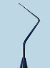
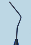
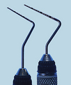
Angle of Shank
Most periodontal instruments have shanks that are curved or bent in at least one and usually two places (Figure 24-4). The degree and angle of this curvature also determine the area(s) in which the instrument is effective:
The smaller the angle and the fewer the number of shank bends, the more suitable for use on anterior teeth. The more acute the angle and the greater the number of shank bends, the more suitable for use on posterior teeth.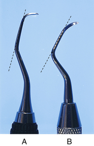
The fulcrum plays a major role in directing the use of the instrument, despite the angle of the shank. Although straighter-shanked instruments are used in anterior areas and the more curved-shanked instruments are used in posterior areas, this does not always have to be the case. For example, clinicians who use a variety of fulcrums ranging from intraoral to extraoral to allow the working end access to deep periodontal areas find that shank angle does not limit instrument usefulness. Fulcrum versatility allows greater flexibility in use of instruments in nontraditional areas. Therefore in some cases, straighter-shanked instruments may be used for scaling of posterior teeth and considerably more curved instruments may be used in anterior areas.
The portion of the shank from the last bend or curve to the working end is termed the terminal shank. Its position as it relates to the working end is important in determining the correct positioning of the angulation of the curet blade, and it usually is kept parallel to the long axis of the tooth.
Shank Strength
All shanks taper in diameter from the handle to the working end. Shank strength, categorized as extra rigid, rigid, moderately flexible, or flexible, is a function of the thickness and type of metal used.
Extra rigid and rigid shanks are for removing very tenacious and heavy calculus. Both are ideal when additional strength is needed and the clinician does not want dissipation of pressure against the tooth surface felt with more flexible shanks. Tactile sensitivity for detecting changes in tooth surface smoothness is not compromised when extra rigid and rigid shank curets are used. Sickles, files, and rigid Gracey curets are examples of instruments with rigid shanks. Moderately flexible shanks, found in most universal curets, are ideal for removal of moderate to light calculus, providing adequate resistance against this type of tooth deposit. Flexible shanks are used to detect and remove light subgingival calculus deposits or oral biofilm. They are characteristic of area-specific curets and explorers, and their flexibility provides the best tactile sensation but least strength as compared with shanks of other strengths.Some manufacturers designate the flexibility of their instruments’ shanks. There are definite benefits in using instruments with less-flexible shanks. When teeth with heavy calculus are scaled, much less operator effort is needed if the instrument does not bend or flex away from the tooth when pressure is exerted. The practitioner must work harder to direct equivalent lateral pressure against the tooth when the instrument shank flexes. In addition, if the instrument shank is long or if fulcruming away from the working area is required, shank flexibility results in further dissipation of pressure exerted by the operator. Consequently, in these cases use of an instrument with a strong shank is important.
In scaling teeth with light calculus or in fulcruming close to the working area, there are also savings in operator effort, although this is less noticeable when an instrument with a strong shank is used. However, if the operator’s saved effort is multiplied by 8 to 10 clients treated per day, the savings become more meaningful.
Nevertheless, arguments against rigid-shanked instruments claim decreased tactile sensitivity compared with flexible-shanked instruments. Many clinicians find the rigid shanks comfortable with all types of clients. Others find that flexible shanks are better for scaling. The decision to select a rigid-shanked or flexible-shanked instrument is largely a matter of what one is accustomed to using. However, it is prudent to learn to use instruments with rigid shanks. Savings in operator effort and possible avoidance of operator injury such as tendonitis of the wrist are most likely to be felt when scaling and root planing teeth with rigid-shanked instruments (see the discussion of hand, wrist, and finger injuries in Chapter 9).
Working End
The working end (terminal end) of the instrument attached to the shank determines the general purpose of the instrument. There are slight differences among manufacturers as to shape, length, width, bend or curvature, and metallurgy of the working ends of identically named and numbered instruments. These details are important considerations when instruments are being selected for purchase.
The working end is designed for a specific task. For example, if an instrument is needed for assessing distance between the marginal gingiva and the base of the periodontal pocket, the dental hygienist selects an instrument that has a working end calibrated to measure distance (e.g., the periodontal probe or Nabers probe). The general shape and length of the probe’s working end are fairly consistent among all manufacturers. However, there are differences in the working ends of periodontal probes with respect to their thickness, intervals of millimeter markings, materials, and presence or absence of color-coded probe markings for easier reading.
The design of the working ends among scaling instruments varies, but most will have a face, two lateral surfaces, one or two cutting edges (blades), and a round or pointed toe. For example, a sickle scaler has two lateral surfaces, a pointed back, and two cutting edges that all join to form a point; a curet has two lateral surfaces (one or two cutting edges), a rounded back, and a face that join to form a rounded toe. Files traditionally have rows of parallel blades on a flat working head; however, a diamond-coated file is shaped more like a Nabers probe with the surface like an emery board. A chisel has a straight, beveled cutting edge on a straight shank, and the hoe has a straight cutting edge at a right angle to the shank (Figure 24-5). When one is deciding which instrument to use for scaling, the criteria for instrument selection are based on experience using different scaling and root planing instruments, periodontal probing depths present, the gingival tissue tone, and the quantity and type of calculus to be scaled. If there is heavy, tenacious subgingival calculus, one type of treatment instrument option is the rigid curet. Within this category of treatment instrument there is a range in variation among manufacturers of the same instrument (e.g., differences in blade size, length, shape, and metallurgy). Curet selection should be based on the amount and tenacity of calculus, pocket depth, alignment of teeth, root proximity, use of intraoral or extraoral fulcrums, and tissue tone. For example, a wide, heavy blade is needed for removal of heavy subgingival calculus; a long blade is necessary for removal of deep subgingival and interproximal calculus. The curvature of the blade is important for specific area(s) being scaled.
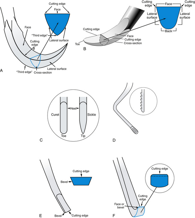
Figure 24-5 Comparison of the working ends of scaling instruments. A, Sickle scaler. B, Curet. C, Comparison of curet and sickle working ends. D, File. E, Chisel. F, Hoe.
(A-F, Adapted from Daniel SJ, Harfst SA, Wilder RS: Mosby’s dental hygiene, ed 2, St Louis, 2008, Mosby. B, From Newman MG, Takei HH, Klokkevold PR, Carranza FA: Carranza’s clinical periodontology, ed 10, St Louis, 2006, Saunders.)
Curets are further subdivided based on blade metal, as follows.
Stainless steel instruments maintain adequate sharpness for scaling and root planing and do not rust or discolor when sterilized with saturated steam or with formalin-alcohol vapor. Carbon steel blades tend to feel sharper clinically and hold their sharpened edges longer after prolonged use than do stainless steel blades. However, carbon steel is more brittle and breaks more easily than does stainless steel. Carbon steel instruments also may corrode or rust when sterilized. Carbon steel has a tendency to oxidize (rust) after saturated steam sterilization or when moisture content of a formalin-alcohol vapor sterilizer reaches 15% or greater. Because of this tendency for oxidation of the carbon steel metal, commercially available corrosion inhibitors are recommended for use with the autoclave to reduce oxidation. Manufacturer instructions concerning dilution of ultrasonic cleaners and chemical disinfection solutions and length of time instruments should remain in solution must be carefully monitored. Dry heat sterilization, however, does not present a problem for carbon steel instruments. Stainless steel alloy that is harder than traditional stainless steel is used in some instruments to reduce the need for sharpening (but not eliminate sharpening) (EverEdge Technology, Hu-Friedy Manufacturing). Instruments made from this material are available as regular and rigid instruments and can be used for fine scaling as well as for removing heavy tenacious calculus, depending on the instrument design. Instruments made of stainless steel impregnated with titanium nitrate (XP Technology, American Eagle Instruments) do not need sharpening and are discarded when the coating is lost and they become dull, in about 3 to 4 months. Instruments made with this material are used for debridement, fine scaling, and root planing of areas associated with nontenacious calculus deposits; however, they are contraindicated for removal of overhangs and tenacious deposits, and for trimming the margins of restorations. Instruments with diamond-coated working ends (coating placed 360 degrees around the tip∗ or 180 degrees around the tip with the back of the instrument smooth for placement against the tissue† are designed for performing final root debridement, polishing root surfaces, and scaling furcations and other narrow inaccessible areas and when using an endoscope. Diamond-coated instrument tips are not designed for scaling heavy calculus.The final selection of a treatment instrument for scaling purposes usually involves personal preference relative to which instrument works best with a given instrumentation technique (grasp, fulcrum, wrist, and finger action), scaling and root planing objectives, tooth and root morphology, and desired efficiency in terms of time management. If, for example, a practitioner’s scaling technique involves using extraoral fulcrums, area-specific curets are ideal instruments to use. If the client has no significant periodontal disease, universal curets may accomplish the scaling with more efficiency in terms of time management than area-specific curets that require different instruments for different areas of the tooth. Furthermore, the new materials that reduce or eliminate the need for sharpening or improve ergonomics also may improve efficiency and reduce RSIs, respectively.
Depending on the manufacturer, the working end of an instrument may be either of the following:
Double-ended, with exact, mirror images on the opposite ends. These mirror images are necessary because the same blade curvature does not adapt to each side of the same tooth. For example, the distal surface from the facial aspect of the tooth requires the mirror image of the same instrument to scale the distal surface from the lingual aspect. Single-ended, with only one end having a working blade, requiring the practitioner to have twice as many instruments. Single-ended instruments are inefficient because of the necessity of picking up and replacing instruments to and from the work area every time the dental hygienist chooses to work from the opposite aspect of the same tooth. Instrument cleaning, packaging, sterilization, and storage efforts also are doubled.Some assessment instruments do not have mirror-image working ends, such as the periodontal probe and the straight explorer. Such instruments may be manufactured so that one end is a periodontal probe and the other is an explorer. These instruments are double-ended but have two different instruments on the same handle (Figure 24-6).

FUNDAMENTALS OF INSTRUMENTATION
Operator and Client Positions
Operator and client positioning facilitate proper instrumentation technique. In operator positioning the dental hygienist attempts to achieve a state of musculoskeletal balance that protects the body from strain and cumulative injury (see the section on positioning factors in Chapter 9).
Instrument Blade Selection
After the appropriate instrument has been selected, the hygienist determines the correct working end of the instrument to use for the tooth surface to be scaled. For some instruments, such as the periodontal probe and the No. 3-A EXD explorer, the working end is universal (i.e., used on all tooth surfaces). For other instruments, such as the straight sickle scaler, the working end will work well on all mesial and distal surfaces, but only on the anterior teeth. The majority of treatment instruments, however, are site-specific, with a definite side of the blade that should be used against a particular tooth surface.
After establishing a comfortable operator position and selecting the appropriate instrument and working end, the dental hygienist begins scaling and/or root debridement. This procedure is broken down into its component parts: grasp, fulcrum, insertion, adaptation, angulation, lateral pressure, stroke direction, stroke length, and reinforcement.
Grasp
Table 9-5 in Chapter 9 categorizes grasp by instrument selection.
Pen Grasp
The pen grasp (Figure 24-7, A) is used when the exacting or directive type of pressure in scaling and root planing is not required. The thumb and index finger pads are well situated on the instrument handle, but the middle finger slips down and the instrument rests on the side of the finger near the first knuckle. The pen grasp may be used when light, easy probing or exploring into nonperiodontally involved areas is performed. Much heavier pressure also may be used with this grasp on the mouth mirror for retraction of the buccal mucosa, tongue, or other soft tissues.
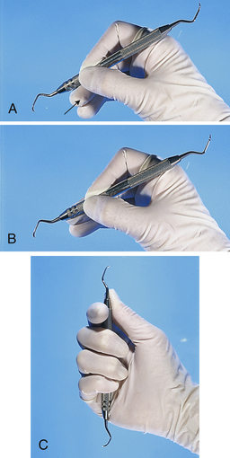
Modified Pen Grasp
The modified pen grasp (Figure 24-7, B) is the standard grasp used for dental hygiene instrumentation. When correctly applied, it is a sensitive, stable, and strong grasp because of the tripod effect produced by the position of the thumb, index finger, and middle finger. The thumb pad must be placed on the instrument handle and the joint bent slightly, depending on the area being scaled. The index finger pad should be on the instrument at a point slightly higher on the handle than the thumb, and the first joint should be slightly bent downward with the second joint cocked upward. The side of the middle finger near the nailbed should be placed opposing the thumb and further down the instrument on the shank toward the working end. The middle finger may remain straight when using extended fulcrums (e.g., cross-arch, opposite arch, and extraoral fulcrums), or it may be angled on the first and second knuckles, similar to the position of the index finger but less pronounced, especially when working with fulcrums in close proximity to the area being scaled.
Once instrumentation is initiated, the modified pen grasp must be continually reestablished on the instrument handle to accommodate the minute rolling of the instrument into and around depressions of tooth structure. Otherwise the instrument can roll and slip out of the grasp, or the thumb and fingers can end up in an undesirable position on the instrument handle, which may not allow for optimal pressure to be placed against the instrument for adequate assessment or instrumentation.
The thumb, index, and middle fingers also are flexed to allow the instrument to be manipulated in various directions around the tooth surface and to allow equal pressure to be applied against root structure during the course of the stroke. Historically, dental hygienists were taught to avoid digital movement during instrumentation, but it now appears that such digital movement, when combined with the movement of the wrist, facilitates accurate, even scaling and root planing strokes in deep periodontal pockets during nonsurgical periodontal therapy. Moreover, the most protective situation for the dental hygienist when scaling in deep pockets occurs when both finger movement and wrist (or arm) movement can be used, minimizing stress to one particular area such as the hand or wrist. The degree to which finger flexing is required for successful instrumentation (versus wrist movement and even arm movement) varies according to the fulcrum used, the area being scaled, the instrument used, and the depth of the periodontal pocket. In certain areas, either finger flexing or wrist movement is used.
Palm-Thumb Grasp
The palm-thumb grasp (Figure 24-7, C) is achieved with all four fingers wrapped tightly around the handle and the thumb placed on the shank in a direction pointing toward the tip of the instrument. This grasp is very awkward and uncontrolled because the thumb provides the only source of pressure and the opposing fingers clumsily wrap around the handle and do not provide a means of turning the instrument or modifying the effect of the thumb. The palm-thumb grasp provides little in the way of tactile sensitivity during scaling procedures and is not recommended for supragingival or subgingival periodontal instrumentation. Because the palm-thumb grasp is a very stable grasp that does not allow the instrument to move on its own, it is ideal for use during instrument sharpening.
Fulcrum
Applying lateral pressure against the tooth surface with a sharp blade or pointed instrument necessitates a stable fulcrum. The fulcrum is the source of stability or leverage on which the finger rests and against which it pushes to hold the instrument with control during stroke activation. When there is no fulcrum, the instrument uncontrollably slips off of the tooth surface when even a slight amount of lateral pressure is exerted. There are two basic fulcrums: intraoral and extraoral.
Intraoral Fulcrum
Established inside the mouth against a tooth surface, the intraoral fulcrum is used for scaling in shallow pockets. The pad of the ring finger usually is positioned on the occlusal, incisal, or facial surface of a tooth close to the one being instrumented. The middle finger should remain in contact with the ring finger even when it is bent during finger flexing or when making digital movements. If the middle finger splits away from the ring finger, control and strength diminish from the stroke. With the added support of the middle finger, a built-up stable fulcrum is established.
Depending on the area to be scaled, the angle of access, and the pocket depth, intraoral fulcrums may be positioned on the following:
The operator’s own finger (e.g., fulcrum on index or thumb), located within the oral cavity (Figure 24-8) A tooth surface on the same arch but across from the area being scaled (i.e., on the opposite quadrant or cross-arch), creating a cross-arch fulcrum (Figure 24-10) A tooth surface on the opposing arch from the arch being scaled (opposite arch fulcrum) (see Figure 24-10)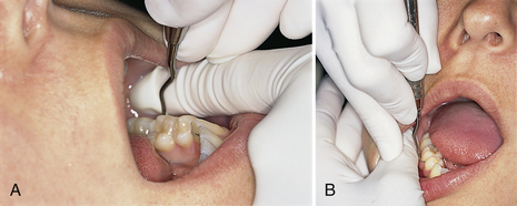
Figure 24-8 Intraoral fulcrums. A, Fulcrum on operator’s index finger. B, Fulcrum on operator’s thumb.
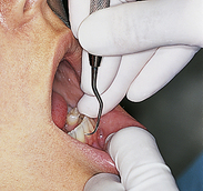
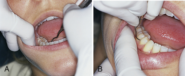
Figure 24-10 A, Cross-arch fulcrum is positioned on the same arch but across from area being scaled; fulcrum on opposite quadrant. B, Opposite arch fulcrum from the arch being scaled.
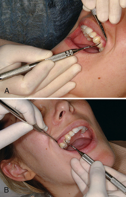
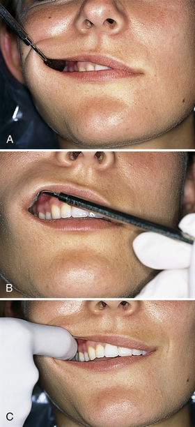
Figure 24-11 External fulcrums. A, Extraoral palm-down fulcrum. The front surfaces of the fingers rest on the left lateral aspect of the mandible while the maxillary left posterior teeth are instrumented. B, Extraoral palm-up fulcrum. The backs of the fingers rest on the right lateral aspect of the mandible while the maxillary right posterior teeth are instrumented.
(From Newman MG, Takei HH, Klokkevold PR, Carranza FA: Carranza’s clinical periodontology, ed 10, St Louis, 2006, Saunders.)
Extraoral Fulcrum
Established outside of the mouth, the extraoral fulcrum is used predominantly when instrumenting teeth with deep periodontal pockets. The extraoral fulcrum is placed against the client’s jaw or on a broad surface such as the side of the face (Figure 24-11, A and B). The extraoral fulcrum does not use a small finger point source as does the intraoral fulcrum. Rather, the extraoral fulcrum is established by placing the broad side of the palm or back of the hand against the chin or outer cheek. The extraoral fulcrum does not use light pressure against the skin of the client’s face. Rather, the palm or backside of the hand rests with moderate pressure against the bony structures of the face and/or mandible. This extraoral fulcrum may be a palm-up, palm-down, knuckle-rest, or chin-cup position. The extraoral fulcrum provides an excellent means of control and stability for access into periodontally involved areas that may be cumbersome or physiologically strenuous for the dental hygienist to instrument using intraoral fulcrums. Often the extraoral fulcrum allows a direct “line of draw” in which the instrument may be pulled straight down, as opposed to rocking with the wrist in areas such as the maxillary posterior regions.
Criticism of extraoral techniques stems from fear of loss of fulcrum stability when fulcruming farther from the working area, when grasping the instrument farther from the working end, and/or when stabilizing the instrument against a slightly mobile surface such as the skin rather than on a solid tooth. In reality, fulcruming away from the immediate working area does not necessarily diminish the stability of the fulcrum. Rather, when instrumenting a tooth surface in a deep periodontal pocket, the leverage and lateral pressure may be increased and extended throughout the length of a long working stroke (scaling or root planing stroke). The loss of control from extending the grasp away from the working end of the instrument can be easily overcome by using reinforcement from the nonworking index finger or thumb to the shank or handle close to the working end of the instrument. Finally, the extraoral fulcrum allows the operator to change the action of pulling the stroke from the wrist to the lower arm, upper arm, and shoulder. Using instrumentation techniques such as these may protect the operator from future injury and stress to the nerves, tendons, and ligaments of the wrist and elbow. Also see the section on reinforcement scaling later in this chapter.
Insertion
Insertion is the act of placing an assessment or treatment instrument into subgingival areas. The purpose of insertion may be to measure the sulcus or pocket depth, classify furcation involvement, explore the subgingival areas, or scale and/or root plane subgingival areas. Whatever the purpose is, the procedure must be nontraumatic and accurate. As with all sharp-pointed instruments, extreme care must be taken when the point is inserted directly toward the junctional epithelium. Too much pressure and lack of proper grasp, fulcrum, and contact points with the instrument as it glides subgingivally may cause perforation through the attachment apparatus.
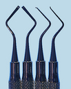
Straight instruments such as the periodontal probe are easily manipulated as long as the side of the tip and the rest of the working end stay in contact with the root when the tip is inserted. A delicate touch using fairly light pressure is required when probing or initially exploring subgingivally. With such exploratory strokes, the junctional epithelium offers a moderate amount of resistance, feels slightly elastic to the touch, and gives with a slight amount of pressure from the instrument. Pressure on the instrument may be increased after the topography of the pocket is understood, to interpret cemental irregularities, calculus, and restorative margins. When a curved explorer is inserted, the tip should be pointed apically and the side of the tip should be in contact with the tooth surface being explored. Care must be taken to avoid tissue distention with the rounded bend and to avoid directing the point right at the root surface. Inaccurate deposit assessment and possible scratching of the root surface result if the pointed tip is directed into the root surface. The only time this is done intentionally is when the dental hygienist suspects root caries or furcation involvement. When evaluating dental caries, probing pressure, as opposed to forceful penetrations, is used against suspected carious areas to avoid worsening the breakdown of the lesion. (See the discussion of dental caries detection in Chapter 14.)
Careful insertion of a bladed treatment instrument into subgingival areas involves closing the angle of the cutting edge of the blade relative to the tooth surface to avoid tissue trauma with the opposite side of the blade and to reach the base of the pocket on the downstroke of insertion. With the curet the closed blade angulation is from 0 to 10 degrees. With sickle scalers (sharp-pointed back and triangular design) the angulation of insertion is slightly more than 10 degrees but much less than the more open “working” angulation (defined as the angle of the cutting edge of the blade against the tooth that produces a grip or bite to the tooth surface).
Reinsertion is the act of returning the instrument down into the subgingival areas after an assessment or working stroke has been accomplished. The reinsertion stroke angulation is slightly closed compared with that of a working stroke. The working end of the instrument should remain in contact with the tooth until instrumentation is complete. A common error with the reinsertion stroke is lifting the instrument from the tooth surface during the act of reinsertion. The dental hygienist should use the same guidelines of following tooth structure down on reinsertion as in the initial insertion to avoid tissue trauma and to accurately reposition the blade for continuous, overlapping strokes.
Adaptation
With regard to pointed assessment instruments, instrument adaptation refers to the alignment or placement of the side of the first few millimeters of the periodontal probe or straight explorer against the tooth. Adaptation is important with assessment instruments because it provides the clinician with an accurate measurement or with information about the smoothness of the tooth surface. If the instrument is not well aligned against the tooth surface, it will be off the tooth and into soft tissue. This lack of alignment leads to client discomfort as well as to misinterpretations regarding probing depths and the presence of calculus deposits or cemental irregularities. Only in instances in which a tooth surface is being assessed for dental caries is the point or tip of such an instrument used directly against the tooth.
Assessment Instruments
The periodontal probe and the explorer are always thin, pointed instruments by design to reach deep, sometimes tight subgingival pockets and to facilitate tactile sensitivity. Because they have to reach under tight tooth contacts to detect calculus and root irregularities, explorers have fine, delicate working ends. As indicated earlier, the tip of an explorer may be used for caries detection; however, open cavities can and should be detected without exploration. Also, to protect tooth structure, tooth surfaces undergoing remineralization should not be deliberately picked or scratched by the tip of an explorer. For caries detection and diagnosis, greater emphasis is now on visual examination, caries detection devices (e.g., Diagnodent Laser Cavity Detection), transillumination, and x-ray examination. However, the side of the tip should always be in contact with the tooth structure to avoid tissue trauma when assessing the presence of cemental irregularities and acquired deposits. The remainder of the explorer’s working end should be as closely adapted to the subgingival tooth surface as possible to avoid excessive distention of tissues, excessive pressure against the instrument from the pocket wall, and the possible use of the point instead of the side of the instrument tip. There is only one working end on the straight periodontal probe and explorer. Although the correct working end is automatically determined, proper adaptation to the tooth surface must be maintained.
With a bent explorer such as the double-ended pigtail explorer, there is a correct and incorrect working end for different tooth surfaces. The first 2 to 3 mm of the side of the toe (or side of the tip of the instrument) must adapt to an area between the base of the pocket and the contact of the next tooth. The rest of the working end should not excessively distend the sulcular tissues.
Treatment Instruments
With instruments used for scaling and root planing, adaptation is the close relationship of the working blade to the tooth surface. When the working blade is well adapted to the tooth surface, it instruments more root surface than does a poorly adapted blade and causes less damage to root surfaces and/or soft tissues. If only the toe or tip is in contact with the tooth, the tooth surface may become gouged or overinstrumented. If the middle or upper third of the blade is in contact with tooth surface and the lower third is off the tooth, the toe is in an open position and may cause tissue trauma to sulcular epithelium (Figure 24-12, A and B). The adaptation position most effective and causing the least amount of hard- or soft-tissue damage occurs when the lower third of the working blade remains in contact with the tooth surface during scaling and root planing procedures (Figure 24-12, C).
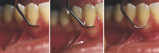
Figure 24-12 Comparison of various adaptations of bladed instrument. A, Upper third of blade. B, Middle third of blade. C, Lower third of blade.
For treatment instruments that have sharp, pointed tips, such as sickle scalers, the dental hygienist uses adaptation guidelines similar to those presented for assessment instruments. If the instrument is a simple straight sickle scaler, for example, there is only one end to use. Proper adaptation with the side of the toe to avoid tissue trauma is as important with the sickle scaler as it is with the periodontal probe and the explorer.
If the sickle scaler has a bent shank and is double-ended, one bladed side is preferable for each tooth surface. The correct end produces the closest adaptation of the blade to the tooth surface and maintains a shank position parallel to the plane of the tooth surface being scaled. The angulation (relationship of the cutting edge to the tooth surface) should be between 45 and 90 degrees to the tooth surface (Figure 24-13).
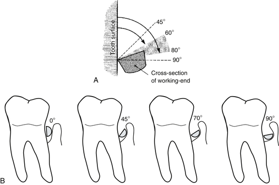
Figure 24-13 A, The correct working angulation of the blade to the tooth should be between 45 and 90 degrees; 60 to 80 degrees is ideal for debridement. B, Insertion angle of close to 0 degrees is ideal for insertion of working end into the pocket; a 45-degree cutting edge to tooth angulation is too closed to remove calculus, and burnishing is likely to occur; a 70-degree cutting edge to tooth angulation is ideal for debridement; a 90-degree cutting edge to tooth angulation is too open, with the potential for damaging adjacent tissues.
(Adapted from Daniel SJ, Harfst SA, Wilder RS: Mosby’s dental hygiene, ed 2, St Louis, 2008, Mosby.)
Adaptation of the curet follows many of the same principles previously discussed. In general, the lower third of the blade is the most desirable portion of the curet blade to contact the tooth surface. However, when broad, flat areas of tooth surface are scaled, the middle third of the blade can be used in addition to the lower third. Most instrumentation difficulties lie in conforming instruments to the varying convexities and concavities found on root surfaces (see Chapter 26). Especially when instrumenting periodontitis-affected teeth, proper adaptation of the curet blade is a continuing process because of root morphology. Instrumentation is further complicated when there is close root proximity on multiple-rooted teeth or from adjacent teeth and furcation involvement. Tooth alignment also complicates procedures. In situations such as these, the most successful adaptation is use of the lower third of the blade, followed by scaling with a diamond-coated file, or a Micro Mini blade curet (Hu-Friedy Manufacturing).
Angulation
Angulation of a bladed instrument refers to the relationship of the cutting edge to the tooth surface (see Figure 24-13). Specifically, this is the measurement from the face of the blade to the tooth surface being scaled.
Angulation between 60 and 80 degrees is ideal for removing calculus and planing roots. This standard allows a range in which to modify the angulation. A more closed angulation (45 to 60 degrees) is recommended when a smoothing, shaving root planing stroke is desired. A more open angulation (near 70 to 80 degrees) is recommended when there is heavy deposit to remove and it is necessary to grab the root surface effectively.Just as in performing proper instrument adaptation, it often is necessary to modulate angulation of the blade. An example of such a situation is when there is heavy calculus only at the base of a 6-mm pocket with smooth cementum directly above. Angulation of the blade is more closed and the pressure applied is heavier at the base of the pocket to remove the calculus. The angulation is more open and the pressure applied is lighter toward the mouth of the pocket for root planing. The procedure is followed by several more strokes at less than 90 degrees for root planing from the junctional epithelium to the cementoenamel junction (CEJ).
Lateral Pressure
Lateral pressure is the pressure of the anterior third of the working end of the instrument against the tooth. This pressure may range from very light to firm, depending on the nature of the roughness of the tooth surface. Therefore it is necessary to use gradations of pressure during exploratory, scaling, and root planing strokes. The grasp, fulcrum, and basic control of the instrument must be strengthened as pressure is increased. This is why the beginning student may experience difficulty in physically applying firm lateral pressure.
Strokes
Exploratory Stroke
The exploratory stroke is used for detection and usually is performed with an explorer or periodontal probe. The curet also may perform an exploratory function to assess the tooth surface during actual scaling or root planing. An exploratory stroke may use light to firm lateral pressure, as follows
Scaling Stroke
The scaling stroke is used for removing calculus from supragingival and subgingival areas. The curet is the instrument of choice for definitive scaling and root planing. As in the exploratory stroke, the lateral pressure used with the scaling stroke ranges from light to firm. The difference, however, is that the magnitude of what is considered firm is far greater during scaling than during exploring. During scaling, the action of the instrument may quickly change from a scaling stroke to an exploratory stroke. This change in lateral pressure is done specifically to break off calculus but not to overinstrument a clean area above or below that calculus. It is performed also to assess areas previously scaled without having to stop and pick up an explorer. It is very efficient to be able to work in this manner and to reserve the use of an explorer for after major areas have been scaled.
The practitioner uses assessment data on pocket depth, clinical attachment, tissue color, tissue consistency, tissue surface texture, tissue size, bleeding, and bone loss to determine the degree of periodontal involvement and the probable amount of lateral pressure needed for calculus detection and scaling. Generally, the more periodontally involved the client’s teeth, the more suspicious the dental hygienist should be of local contributing factors such as subgingival calculus harboring oral biofilm. If the calculus occurs in the form of ledges, any amount of pressure is likely to detect it. If, however, the calculus formation is flat and smooth, medium or even firm exploratory strokes may be necessary to detect the deposit.
Calculus density may be determined by radiographs and most accurately by “hardness” felt with the explorer. Dense calculus appears more radiopaque than lighter, easier-to-remove calculus. Dense calculus feels hard, like tooth structure, as opposed to the porous feel of lighter calculus. In situations in which there is dense calculus and naturally grainy or rough root surfaces, the calculus is likely to be embedded in the root surface. Calculus deposits that are both dense and tenacious make scaling more difficult than with light calculus deposits.
The older and more dense the calculus, usually the more tenacious it is. The practitioner increases the lateral pressure of the scaling stroke as the tenacity and density of the calculus increase. Too little lateral pressure on instrumentation may cause burnishing of tenacious calculus on cementum. To avoid indiscriminately applying too much lateral pressure on instrumentation, causing unnecessary gouging and overinstrumentation of root surfaces, the dental hygienist should evaluate the changes occurring on the root surface during instrumentation with the curet using exploratory strokes or by using a dental explorer. Lighter lateral pressure during scaling strokes is indicated for light and easy-to-remove calculus.
Root Planing Stroke
The root planing stroke is used for shaving embedded calculus from cemental surfaces and smoothing roots. The rationale for root planing lies in the fact that clean, smooth roots are more biologically acceptable for connective tissue reattachment than are rough roots, accounting for a reduction of periodontopathic bacteria. In addition, the client’s ability to maintain soft-tissue health is improved because oral biofilm control is easier when the roots are smooth.
Successful root planing requires extremely good control; dedication to smoothing subgingival surfaces evenly from the junctional epithelium to the CEJ; knowledge of root morphology; and a sense of the dimensions of this subgingival space and the area the curet has covered. The root planing stroke is a longer stroke than the scaling stroke and may begin with firm lateral pressure if there is significant root roughness to smooth. The change to lighter lateral pressure should occur rather quickly as the curet moves to even out the surface of the cementum.
The thickness of cementum varies, but it is thinnest at the cervical third of the tooth (0.02 to 0.05 mm). In scaling and root planing tooth structure with such a thin covering of cementum, it is easy to visualize how removal of cementum often occurs during indiscriminate root planing, leading to exposure of dentin and dentinal hypersensitivity (see Chapter 38). To avoid client hypersensitivity, the dental hygienist explores the area carefully and uses lateral pressure discriminately during scaling and root planing with the purpose of removing only subgingival calculus and altered cementum, smoothing the root surface, and removing as little healthy cementum as possible to achieve good results. (See the discussion of clinical and therapeutic endpoints in Chapter 28.)
Stroke Direction
For accurate identification and removal of deposits, a combination of three basic stroke directions is used with assessment and treatment instruments, as follows:
Using combinations of different stroke directions is referred to as a “basketweave of strokes” (Figure 24-14). Varying stroke direction allows a greater possibility that an area of burnished or smooth calculus may be detected because the instrument may catch one side of the calculus when all other sides may be smooth. Both the explorer and the probe are activated beginning with a gentle insertion or downward stroke into the pocket. This exploratory stroke is used as part of the detection process as long as the side of the tip is well adapted to the tooth surface.
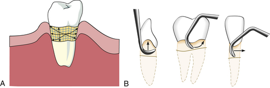
Figure 24-14 A, This diagram illustrates vertical, horizontal, and oblique stroke directions. B, Three basic stroke directions: vertical (left), oblique (middle), and horizontal (right).
(A, Redrawn from Pattison A, Pattison G: Periodontal instrumentation, ed 2, Norwalk, Conn, 1992, Appleton and Lange. B, From Newman MG, Takei HH, Klokkevold PR, Carranza FA: Carranza’s clinical periodontology, ed 10, St Louis, 2006, Saunders.)
The working stroke of the curet, sickle, file, and hoe is performed with a pull stroke. The direction of the pull stroke may be vertical, horizontal, or oblique, and it is not directed toward the junctional epithelium. The push or insertion stroke with working pressure is not recommended with treatment instruments because it causes unnecessary client discomfort and could violate the integrity of the client’s intact junctional epithelium by forcing dental calculus and oral biofilm through the membrane, potentially causing a periodontal abscess.
Once an efficient stroke direction has been established, it is best to keep moving forward in the direction of the toe of the instrument. Short, overlapping strokes for calculus removal and longer, overlapping strokes for root planing maximize root coverage.
Stroke Length
Stroke length is limited by the tissue tone, the morphology of the tooth structure, and the client’s periodontal probing depth measurements. Loose and inflamed tissue accommodates the movement of long, sweeping, overlapping strokes. However, if the tissue is healthy or fibrotic in tone and positioned tightly against the tooth, short, overlapping, well-adapted strokes are indicated to prevent tissue trauma.
Short, overlapping strokes and a firmly planted fulcrum provide for good operator-controlled strokes. When managing the curvatures common to most root surfaces, shorter strokes do not pass over deposits in root depressions as easily as longer strokes and therefore are more reliable. On relatively flat areas such as the palatal roots of maxillary molars, however, one may use long stroke lengths and still maintain a controlled, effective movement.
Deep periodontal pockets allow for greater flexibility in stroke length than do shallow pockets because of greater root surface area from clinical attachment. Where there is recession there also may be significant root surface. Therefore, with greater pocket depth or more exposed root surface area, it is easier to vary stroke length than where pocket depth is very shallow with little recession.
To remove calculus, the scaling stroke is a short pull stroke. The short stroke is best for calculus removal because the increased pressure needed reduces stroke control. A short stroke facilitates a controlled stroke. For root planing, the stroke length should be increased and the pressure lightened once the calculus has been removed.
Reinforcement Scaling
Reinforcement scaling is the use of the nondominant hand to support the instrument or the working hand, providing additional lateral pressure during instrumentation procedures. In general, the index finger and thumb of the nondominant hand do the work of reinforcing. Either finger or both may be applied to the instrument or to the operator’s working hand, usually near the thumb or the muscle area near the thumb (thenar muscle; see Chapter 9). Reinforcements are used only with treatment instruments such as curets. They are not necessary with assessment instruments because control and lateral pressure are not difficult with these instruments. Reinforcements provide additional support and lateral pressure in deep periodontal pockets, particularly with extended fulcrums (cross-arch, opposite arch, and extraoral) placed away from the immediate area being scaled. Several reinforcements make scaling easier and more controlled and accurate; each is discussed later in this chapter.
Customizing Instrumentation for Periodontitis-Affected Teeth
When instrumenting periodontally involved teeth, the method of scaling and root planing varies because of individual facial anatomy, alignment of teeth, and extent of periodontitis. Some individuals have large dental arches, and others have very small ones; some have nearly perfect tooth alignment, and others have severely crowded teeth; some clients have limited ability to open the mouth for access into posterior regions. Clients may have normal, healthy periodontium or moderate to severe periodontal problems even within the same arch. Variations require customization of basic instrumentation technique to treat a particular individual successfully. Customizing instrumentation in periodontitis-affected areas allows the clinician to reach almost any area of the mouth, to reach both sulcus areas and deep periodontal pockets, and to manage difficult root anatomy with the control and strength needed for effective care (Box 24-1).
BOX 24-1 Guidelines for Customizing Instrumentation
This is the best grasp when applying a treatment instrument against a tooth surface.
Refer to the general operator positions in Chapter 9Table 9-7Figure 9-8.
This position may be intraoral (same quadrant, cross-arch, or opposite arch) or extraoral.
Initially adapt at least the first 2 to 3 mm of the blade to the tooth surface.
Adjust the angulation of the blade between 60 and 80 degrees for scaling and root planing. The dental hygienist should feel the instrument bite the tooth surface.
During the manipulations that occur while the practitioner adapts and angulates the instrument to the tooth surface, the grasp may have changed. Because the handle is positioned for the tooth surface, it changes the angulation if the handle is moved back to the original grasp; therefore the position of the grasp must be adjusted to the new position of the instrument handle.
The hand may now be in a slightly different position than it was when the general fulcrum position was found. Within the space of this new position into which the grasp has moved, a stable fulcrum position may be established. This fulcrum may be moved to the opposite arch or to an extraoral position if the fulcrum close to the area being scaled does not allow correct adaptation and angulation.
The practitioner moves to a body position that keeps the hand, arm, and possibly the shoulder in line with the direction of the stroke and allows them to move as one unit. This helps distribute the workload and mitigates the stress on the hands and wrist. The body position may range from 8 o’clock to 4 o’clock for both the right-handed and left-handed clinician, depending on the area to be scaled.
The further the fulcrum is from the area being scaled, the more useful reinforcement with the nondominant hand becomes. The reinforcement hand can provide stabilization, additional pressure, additional pulling strength, support for the client in opening the mouth, and retraction of lips and buccal mucosa.
Customizing instrumentation successfully depends on finding the correct fulcrum. The dental hygienist does the following:
Fulcrums intraorally near the tooth being scaled—cross-arch, opposite arch, or on the index finger or thumb of the nondominant hand—or finds a comfortable extraoral fulcrumIf the shape of the tooth surface changes to the degree that one fulcrum position no longer works, the process must be repeated from that point and the fulcrum altered to accommodate the change. With experience, adjustments are made within seconds. Because treatment is customized, the working environment is safer, less stressed, and more effective in meeting client needs.
Traditional instrumentation is based on setting the fulcrum first. Establishing the fulcrum first, however, does not allow for variations in probing depths or alterations in root anatomy, which affect the amount and direction of lateral pressure that can be applied to the root surface. For instance, as probing depth increases on the distal aspect of a mandibular molar from 3 mm to 10 mm, the dental hygienist may find a change in the plane of the root surface from a vertical to a slightly more oblique or horizontal inclination. In subgingival instrumentation of periodontitis-affected teeth, such slight changes in the plane of a tooth surface alter stroke effectiveness. By setting the fulcrum first and not readjusting the fulcrum as the instrument maneuvers into pocket depth, the practitioner is limited in producing effective lateral pressure.
INSTRUMENT SHARPENING
See the discussion of instrument factors in Chapter 9.
Rationale
The objective of instrument sharpening is to restore blade sharpness while preserving the original contours and angles of the instrument. The basic clinical outcome of using sharp versus dull instruments is delineated in Table 24-3. Sharp instruments improve client comfort and decrease operator fatigue by working to remove dental deposits effectively, and are easier to control than dull instruments because they do not slip as readily over tooth surfaces.
TABLE 24-3 Clinical Outcomes Using Sharp versus Dull Instruments
| Outcome | Sharp Instrument | Dull Instrument |
|---|---|---|
| Tactile sensitivity | Increased | Decreased |
| Client safety and comfort | Increased | Decreased |
| Working efficiency | Increased | Decreased |
| Control | Increased | Decreased |
| Lateral pressure | Decreased | Increased |
| Probability of burnished calculus | Decreased | Increased |
To maintain effectiveness and quality of client care, at the first sign of instrument dullness, the dental hygienist should sharpen the instrument. If the instrument is made with a material that requires no sharpening and it becomes dull, the instrument is discarded. The clinician should consider instruments made with materials that require less sharpening (EverEdge Technology) to no sharpening (XP Technology). Traditional methods for sharpening individual instruments are discussed under each instrument subheading. Instruments can also be sharpened with mechanical honing devices such as the Sidekick (Hu-Friedy Manufacturing) or the InstRenew Sharpening Assistant (Nordent Manufacturing).
Sharpening Stones
Natural and synthetic sharpening stones for sharpening dental instruments are composed of abrasive crystals that are harder than the metal of the instrument (Figure 24-15).
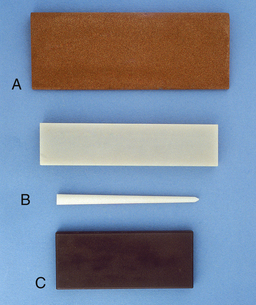
Figure 24-15 Sharpening stones. A, India stone. B, Arkansas stone (flat- and cone-shaped). C, Ceramic stone.
(From Boyd LRB: Dental instruments: a pocket guide, ed 3, St Louis, 2009, Saunders.)
Natural Stones
The Arkansas stone, a natural stone with a fine texture, is manufactured in a variety of shapes for sharpening instruments. Conical and cylindric Arkansas stones are used for sharpening the face of curets, a practice that tends to weaken the blade. The India stone, also a natural stone, comes in a medium texture that removes metal easily, and therefore sharpening with an India stone should be followed by use of an Arkansas stone to provide a polished edge. Natural stones such as the Arkansas and India are usually lubricated with clear, fine oil to facilitate the movement across the stone, reduce friction, and reduce the problem of metallic particles embedding into the surface of the stone. Stones should be washed and/or ultrasonically cleaned to remove excess oil. The stone is then placed in the instrument cassette for sterilization. Steam, chemical vapor, or dry heat may be used to sterilize these stones.
Synthetic Stones (Composition and Ceramic Stones)
The composition stone is a mounted rotary stone, and the ceramic stone is manufactured as a hand-held rectangular stone. Both stones are of medium coarseness and are lubricated with water. The rotary stone may be adapted to the face as well as the edge of the curet. The rectangular stone is used only against the side of the curet or scaler.
Sharpening Stone Selection
Fine stones such as the Arkansas or medium-textured India stones are preferable for the novice or for sharpening during client treatment when little sharpening is required for reestablishment of a cutting edge. Coarsely surfaced stones remove metal at a faster rate than do finely surfaced stones and should be used on instruments requiring significant recontouring. Less pressure, fewer strokes, and greater accuracy are needed with coarsely textured stones. Rotary-mounted stones (e.g., composition stone) are considerably more abrasive than coarse handheld stones because the stone is mounted on a metal mandrel and used in a motor-driven handpiece. The mounted rotary stone should be used only when major instrument recontouring of instruments is required. Lack of good control, friction, and rapid wearing of the instrument are disadvantages of the rotary-mounted stone.Manual Sharpening Technique
To begin instrument sharpening, select the proper sterilized, lubricated stone for the amount of sharpening to be done. Techniques for using handheld sharpening stones consist of either of the following:
Moving the instrument over the stone (recommended for sharpening flat surfaces such as the hoe or sickle scaler)With either method, movement is initiated by the operator’s dominant hand.
To guard against accidental clinician injury when moving the stone against the sharpening instrument, care must be observed in length of stroke, grasp of stone, and grasp of instrument. Short, even, continuous strokes tend to keep the instrument on the stone. The hand holding the instrument should assume a palm-thumb grasp and be supported against a firm surface such as a cabinet top, or the operator’s own elbow may be pulled close to the body to support the wrist and hand holding the instrument. The fingers holding the stone should not be wrapped around the stone on the long side exposed to the cutting surface but should be positioned behind the cutting surface or at the short end of the stone (Figure 24-16).
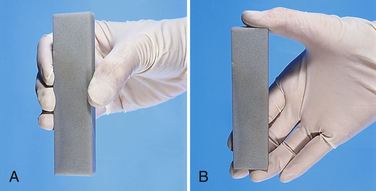
Figure 24-16 A, Incorrect finger position on stone; fingertips are exposed to possible injury if stone slips. B, Correct finger position on stone.
Before the sharpening stroke is initiated, proper angulation of the stone to the surface of the instrument is assumed, and continuous sharpening motions at this constant angle are made across the length of the cutting edge. (Correct angulation of stone to cutting surface is discussed under each individual instrument.) The amount of pressure applied should be determined by the amount of recontouring necessary to produce a sharp blade. Greater pressure exerted against the blade with the stone removes more metal. Prudent advice for instrument conservation is to limit sharpening procedures to what is necessary. The last sharpening stroke(s) should be away from the face of the instrument in a downward motion to remove small metal particles called flash that adhere to the edges of the instrument. The practitioner should wipe the blade with a 2-inch × 2-inch gauze square to aid in removing oil and metal shavings floating on the surface of the instrument.
Mechanical Sharpening Technique
A number of manufacturers offer mechanical devices, also known as honing devices, for sharpening instruments. The Sidekick (Hu-Friedy Manufacturing) is one example of a battery-operated sharpening device that has a ceramic stone and built-in channel guides and vertical stops for maintaining a perfect angulation of the instrument blade against the stone. Once the desired angulation of the working end against the stone is achieved, the stone is automatically activated and moves gently across the working end to create a sharp blade. The device can be used for sharpening sickle scalers, universal curets, and Gracey curets. The device removes metal from the lateral sides of the working end and has a toe guide to maintain the round toe of curets. After instrument sharpening, the ceramic stone, guide plates, and screw can be cleaned in an ultrasonic cleaning unit and then autoclaved (see Chapter 9, Figure 9-10).
Testing for Instrument Sharpness
Testing for sharpness is done by visual inspection or by comparing the sharpness before and after the procedure using a plastic testing stick.
With visual inspection, it is important to have a strong light such as the dental light for viewing. With this test the sharp instrument does not reflect light at the junction between the face and the lateral side of the instrument. In contrast, the dull instrument is beveled on the cutting edge and reflects light back to the observer. With the tactile test, the sharpened blade of the instrument at the proper working angulation engages a hard plastic stick. When using this method, it is important to test the instrument fully across the length of the blade and to resharpen any area that allows the instrument to slip over the stick.When testing for sharpness, the dental hygienist examines the shape of the sharpened blade. To protect the client against unnecessary instrument breakage, all instruments that have lost their original strength or are too fine to remove heavy deposits or reach deep pockets should no longer be used in such areas. Instruments that have been sharpened down and are of moderate or fine dimensions may be used for the healthier individual with little calculus formation and shallow probing depths. The instrument is retipped or discarded when it is no longer functional or is of danger to the client from possible breakage.
Managing Instrument Tip Breakage
When an instrument breaks subgingivally, only the tip breaks off, leaving it for the dental hygienist to locate. To retrieve the small metal fragment the dental hygienist stops instrumentation as soon as the instrument tip has broken and informs the client. Low-speed or high-speed aspiration (suction) should be discontinued, and the client should use a cup to expectorate into (in case the tip is floating in saliva) until the tip is found. Techniques for locating the broken piece include the following:
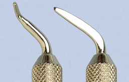
Figure 24-17 Magnetic broken tip retrievers (Schwartz Periotrievers). Contra-angled tip is for use in furcations; the long tip is for use in pockets.
(From Newman MG, Takei HM, Klokkevold PR, Carranza FA: Carranza's clinical periodontology,ed 10, St Louis, 2006, Saunders.)
Radiographic examination is helpful during these exploration techniques to locate the metal tip. It should be noted that even new instruments, especially curets, break if they are lodged in a tight area such as under a contact and are twisted or pulled in a direction in which the toe may not be released. If the broken tip cannot be clinically located or if it is not visible on a radiograph of the area, the tip may be outside of the sulcus. A complete visual inspection of the oral cavity is begun. Gauze squares are used to wipe out the vestibular areas and areas under the client’s tongue. They then are carefully inspected for the broken tip. In the event that the tip cannot be located, a chest radiograph is indicated to rule out the possibility that the client has aspirated it.
INSTRUMENT TYPES
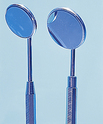
Mouth Mirror
Design and Use
The dental mouth mirror is used for the following purposes (Table 24-4):
TABLE 24-4 Functions of the Dental Mouth Mirror
| Function | Reason for Use |
|---|---|
| Indirect vision | |
| Indirect illumination | Use to catch light and direct increased illumination to intraoral areas. When mirror is being used in this capacity, it cannot be used for indirect vision at the same time. Therefore operator and client position must be adjusted for direct-vision scaling. |
| Transillumination | |
| Retraction |
Moistening the face of the mouth mirror by gently rubbing it against the buccal mucosa or dipping it in a commercial mouthwash prevents mirror fogging.
The traditional mouth mirror has a handle and mirror, each with a threaded design or cone-socket attachment. The handle and mirror components are separated, ultrasonically cleaned, and autoclaved after each appointment. Unlike the mirror heads, which eventually become clouded or scratched, handles rarely need to be replaced. Wrapping the mirror heads with 2-inch × 2-inch gauze squares when packaged with other instruments during sterilization minimizes scratching.
Mirror heads come in a variety of sizes from ⅝- to 2-inch diameters. Mirror size selection is made according to the size of the client’s mouth, the operator’s ability to place the mirror and instrument within a confined space, and the operator’s comfort in holding and using a certain size mirror head. Three types of mirror faces include the following (Table 24-5):
TABLE 24-5 Types of Mouth Mirror Surfaces
| Type | Advantages and Disadvantages |
|---|---|
| Front surface | Mirror surface is on the front of the glass; therefore the image produced is the mirror image of the area reflected. Most commonly used because there is no distortion or magnification of the image. |
| Concave surface | Causes magnification of the image. Because each movement visualized with this mirror is magnified, the operator needs to relate the scale of movement and the image differently from the way it actually appears. More difficult to use than the front-surface mirror. Does not allow the operator to see as wide a range as the front surface mirror and causes distortion, even dizziness, for some clinicians. Not recommended unless eyestrain or vision is a significant problem. |
| Flat surface | The image appears doubled or shadowed. Not recommended for periodontal procedures. |
The mouth mirror generally is held with a modified pen grasp; however, other grasps also may be used. The pads of the thumb and the index and middle fingers all rest on the shank and handle of the instrument with the modified pen grasp. Because of its stability, the modified pen grasp should be used when there is resistance to the mirror head, such as during the retraction of buccal mucosa or the tongue (Figure 24-18, A).
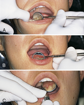
Figure 24-18 A, The modified pen grasp is used for stability when there is resistance (e.g., from the tongue) against the mirror head. B, The modified pen grasp is used for indirect vision and illumination with mirror. C, Use of the mirror hand for mirror placement and reinforcement of scaling instrument.
When there is no resistance and when indirect vision, indirect illumination, and/or transillumination are the goals, the standard pen grasp is adequate and perhaps desirable. The standard pen grasp yields a very loose grasp that generally allows easy, fluid movement of the mirror head around the mouth. This range of movement is beneficial when large oral areas are examined or compared.
For indirect vision or illumination and reinforcement of a curet with the nondominant hand, the mirror is held between the middle and ring fingers. This position allows little manipulation of the mirror; however, in areas where reinforcements with indirect vision are needed, positioning changes of the mouth mirror are minimal (Figure 24-18, B and C).
Because the mouth mirror is used for retraction, care is taken to avoid tissue trauma with the handle or shank of the instrument, particularly at the commissures. This injury may be as slight as soreness or as serious as initiation of herpetic lesions on the client’s lips. Trauma can be avoided by maintaining less pressure on stretched lips. In addition, the mouth mirror should never be allowed to rest on sublingual tissue because doing so causes client discomfort (Figure 24-19).
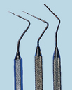
Periodontal Probe
See the discussion of periodontal probes in Chapter 17.
Design and Use (Table 24-6)
The periodontal probe, a slender, tapered, blunt instrument with millimeter markings, is used to determine the following:
TABLE 24-6 Periodontal Probe: Use, Technique, and Significance of Results (see Chapter 17)
| Measurement | Technique and Significance of Results |
|---|---|
| Probing depth | Measures probing depth from marginal gingiva to junctional epithelium. Six measurements are taken around each tooth (distofacial, facial, mesiofacial, distolingual, lingual, and mesiolingual). The deepest measurements are recorded for each surface. Within any sextant, it is easier to record all facial surface measurements, then all lingual surface measurements. Probing depth is an important indicator of past disease activity (see Procedure 24-2). |
| Clinical attachment level | Measurement from the cementoenamel junction to the junctional epithelium. The technique is similar to measurement of probing depth, except that the depth is measured from the junctional epithelium to a fixed reference point. When measuring from a fixed reference point, a clearer picture of bone loss can be determined, especially when recession and minimal probing depths are present. |
| Relative attachment level | Measurement from a fixed reference point on the tooth or a stent to the junctional epithelium. The technique is similar to assessing probing depth and offers a record of past disease activity. |
| Amount of attached gingiva | Attached gingiva is the keratinized stratified squamous epithelium firmly attached to the cementum and alveolar bone. Adequate attached gingiva is an important safeguard against future mucogingival defects and recession when there is bone loss. |
| Gingival recession | Measurement from the gingival margin to the cementoenamel junction. This measurement is another indicator of apical migration of the attachment apparatus. |
| Furcation invasion | See Chapter 17 for classifications. The No. 2 Nabers probe is a specialized probe used for furcation detection and classification. Detection of furcation invasion is critical to the therapy and long-term prognosis of the tooth and adjacent bone. |
| Bleeding on probing | Observation of bleeding on light probing is a primary clinical indicator of gingival inflammation. |
| Pathologic lesions | An important aspect of assessment is an accurate description of the size and shape of the lesion. The periodontal probe is used for measurement of pathologic lesions. |
| Distance between teeth | The periodontal probe is used to measure the distance between teeth (diastema), overjet, and migration of teeth with severe periodontal disease. |
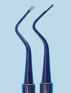
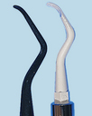
Millimeter markings and other design differences vary among manufacturers. For example, the Marquis probe is marked at the 3-, 6-, 9-, and 12-mm intervals; the Williams probe is marked at the 1-, 2-, 3-, 5-, 7-, 8-, 9-, and 10-mm intervals. Differences in markings, color-coding, shapes, materials used, and an automated probe are shown in Figures 24-20 and 24-21. The Colorvue Probe (Hu-Friedy Manufacturing) offers the option of using replaceable and flexible yellow tips with 1-mm or 3-mm black markings for contrast with the gingiva. The white PerioWise Friendly Probe (Premier Dental) has a green band at 3 mm or less; red millimeter markings are present at 5 mm or 6 mm and thereafter to clearly indicate disease. The EasyView Probe (Paradise Dental Technologies) is a thermal resin probe with yellow and green bands at 3, 6, 9, and 12 mm or 3, 5, 7, and 10 mm. Personal operator preference determines selection of interval and color-coded markings of the periodontal probe. In the case of failing dental implants, which require the use of plastic probes (see Figure 24-21, A and B), safety against further injury and scratching of the titanium implants determines instrument selection (see Chapter 57 on osseointegrated dental implants).
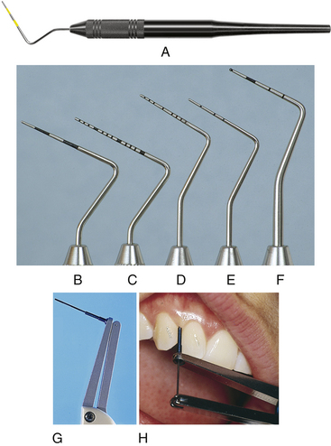
Figure 24-20 Examples of periodontal probes. Note the differences in markings. A, AEP12Y/GX Probe with green band at 3 to 6 mm and yellow band at 9 to 12 mm. B, Marquis color-coded probe with markings at intervals of 3, 6, 9, and 12 mm. C, UNC-15 probe, a 15-mm-long probe with millimeter markings at each millimeter and color coding at the fifth, tenth, and fifteenth mm. D, University of Michigan O probe with Williams markings at 1, 2, 3, 5, 7, 8, 9, and 10 mm. E, Michigan O probe with markings at 3, 6, and 8 mm. F, World Health Organization probe, which has a 0.5-mm ball at the tip and millimeter markings at 3.5, 8.5, and 11.5 mm and color coding from 3.5 to 5.5 mm. G, Florida Probe Computerized Periodontal Probing and Patient-Education System. H, Florida Probe positioned in periodontal pocket.
(A, Courtesy American Eagle Instruments, Missoula, Montana. B to F, From Newman MG, Takei HH, Klokkevold PR, Carranza FA: Carranza’s clinical periodontology, ed 10, St Louis, 2006, Saunders. H, Courtesy Florida Probe Corporation, Gainesville, Florida.)
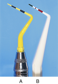
Figure 24-21 Examples of plastic periodontal probes. A, Hu-Friedy black and yellow color-coded replaceable plastic periodontal probe tip. B, Premier Dental Products reusable plastic periodontal probe.
When the probe design is flat and too thick or wide, it is difficult to manipulate the instrument into and around narrow, tight areas for accurate measurement. Conversely, if the probe is too fine and sharp, there is danger of trauma and perforation through the nonkeratinizing junctional epithelium, resulting in inaccurate readings. If too fine a probe is selected, client comfort and safety become important factors to consider. Thin instruments are also subject to damage during sterilization procedures.
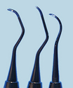
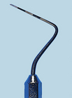
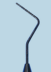
Variations of the periodontal probe, criteria for selection, design, and procedures are found in Table 24-7 and Procedures 24-1 and 24-2. A variation in shank design of the periodontal probe is shown in Figure 24-22. This periodontal probe design (Hu-Friedy Novatech) features a right-angle tip that is color-coded. It offers ease of access in posterior distal surfaces.
TABLE 24-7 Periodontal Probe Design
| Probe Examples | Design and Use Characteristics | |
 |
Marquis Color-Coded Probe | |
| Shank | Thin, round, and tapered. | |
| Measurement | Alternately color-coded at 3, 6, 9, and 12 mm. | |
| Tip design | Thin tip. | |
| Advantages | Color-coding every 3 mm makes it easy to read. | |
| Disadvantages | ||
 |
Williams Probe | |
| Shank | Round and tapered. | |
| Measurement | 1, 2, 3, 5, 7, 8, 9, and 10 mm. | |
| Tip design | Thin to thick, depending on manufacturer. | |
| Advantages | Spaces between 3 and 5 and between 5 and 7 minimize confusion. | |
| Disadvantages | Markings are difficult to read. | |
 |
Michigan O Probe | |
| Shank | Thin, round, and tapered. | |
| Measurement | 3, 6, and 8 mm. | |
| Tip design | Thin tip. | |
| Advantages | Thin shank allows access into tight fibrotic sulci. | |
| Disadvantages | Markings end at 8 mm. | |
 |
Goldman Fox Probe | |
| Shank | Flat. | |
| Measurement | 1, 2, 3, 5, 7, 8, 9, and 10 mm. | |
| Tip design | Blunt or wide. | |
| Advantages | No mark at 4 and 6 mm. | |
| Disadvantages | Flat shank does not allow easy access into tight fibrotic pockets. | |
 |
UNC-12 Probe and UNC-15 Probe (University of North Carolina) | |
| Shank | Thin, round, and tapered. | |
| Measurement | ||
| Tip design | Thin tip. | |
| Advantages | ||
| Disadvantages | Not applicable | |
 |
Novatech Probe | |
| Shank | Upward and right-angled bend. | |
| Measurement | Available in a variety of designs. | |
| Tip design | Available in a variety of designs. | |
| Advantages | Easier access in posterior distal areas. | |
| Disadvantages | May feel bulky due to angulation. | |
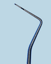 |
PSR Screening Probe (World Health Organization Probe) | |
| Shank | Thin, round, and tapered. | |
| Measurement | 0.5, 3.5, 5.5, 8.5, and 11.5 mm. | |
| Tip design | Thin tip with ball tip. | |
| Advantages | ||
| Disadvantages | Markings at 0.5 mm. | |
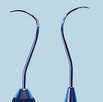 |
Nabers Furcation Probe | |
| Shank | Round, tapered, and curved. | |
| Measurement | Available with or without measurement markings. | |
| Tip design | Blunted tip. | |
| Advantages | ||
| Disadvantages | May feel bulky when clinician is accustomed to using a periodontal explorer for furcation detection. | |
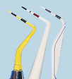 |
Plastic Probe (Particularly for Dental Implants) | |
| Shank | Thin, round, and tapered. | |
| Measurement | Color-coded and variable measurements depending on manufacturer. | |
| Tip design | Thin tip or ball tip. | |
| Advantages | ||
| Disadvantages | Markings wear away. When this occurs, the entire probe or unscrewed probe tip needs to be thrown out. | |
Procedure 24-1 BASIC POSITIONING FOR ASSESSMENT AND TREATMENT
STEPS
Operator Positioning
Procedure 24-2 USE OF THE PERIODONTAL PROBE
STEPS
Fulcrum and Fulcrum Pressure
Insertion and Adaptation
Activation and Direction of Stroke
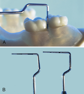
Figure 24-22 A, Hu-Friedy Novatech periodontal probe with its upward bend is designed for access in posterior areas. B, Type of probe tip may differ, as illustrated in this photograph.
Probing inaccuracy is related to probe design, pressure applied, contour of the tooth, contour of the periodontal defect, degree of inflammation, and accompanying loss of collagen fibers. Probing depth usually correlates with attachment loss, but it is always an objective measure of the distance between the base of the pocket and the crest of the gingiva regardless of the degree of attachment loss (recession). Readings may change over time owing to changes in the position of the gingival margin. When probing the full mouth, the practitioner begins the probing sequence from the distal surface. The periodontal probe is held with a pen grasp or a modified pen grasp because control and sensitivity may be accomplished with either grasp. The dental hygienist selects the intraoral or extraoral fulcrum that allows access into the area being assessed. The instrument is advanced by moving up and down and forward in 1- to 2-mm increments, gently inserting to the junctional epithelium on each downstroke. The least amount of trauma to the client occurs when the side of the probe maintains tooth contact during stroke activation. When using a flat-shaped periodontal probe, it is important for the operator to keep the flat side of the instrument against the tooth. For accuracy of interproximal readings, the probe should be slightly angled to examine the site under the col area and at the same time positioned vertically to touch the contact between the adjacent teeth (Figure 24-23).
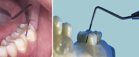
Figure 24-23 For proximal readings, periodontal probe is slightly angled under the col and positioned vertically to touch contact area between adjacent teeth.
Measurement of the probing depth is made by reading the marking on the probe where the gingival margin lies or by adding the increments above the gingival margin and subtracting from the total number of markings on the probe. For information on the measurement of probing depth, clinical attachment, relative attachment, adequacy of attached gingiva, and gingival recession, see Chapter 17 and Table 24-6.
Computerized periodontal probes are also available, for example, the Florida Probe (see Figure 24-20, G and H). The tip of the probe is inserted into the sulcus or pocket and, with the use of a foot pedal, the system automatically records pocket depth, attachment loss, bleeding, mobility, and other clinical parameters. Once data are collected, a graphic chart can be printed and used as part of the dental record, for client education, and for research. The computerized probe applies 15 g of pressure each time it is used. This design feature increases consistency in the probing technique over time and among practitioners. Some computerized probes are accurate to 0.2 mm, exceeding the accuracy of a traditional marked probe.
The blunted tip of the periodontal probe makes it ideal to determine (but not measure) bleeding tendencies on probing. If gentle probing elicits bleeding, this observation should be noted on the client’s record as a clinical indication of inflammation. Gingival bleeding is associated with significant increases in spirochetes, motile bacterial forms, and increased flow of gingival crevicular fluid. Evidence of bleeding has only a 30% predictive value in determining future clinical attachment loss. Cessation of bleeding is related to a significant reduction in gingival inflammation and is used to monitor periodontal treatment outcomes.
By compressing the side of the probe tip against the attached gingiva, the dental hygienist evaluates tissue tone without producing trauma. More information may be obtained from a standard dental index such as the Silness and Löe Plaque Index, which uses the periodontal probe in the assessment (see Chapter 15, Table 15-5). Some practitioners use the periodontal probe to identify subgingival calculus; however, most find a dental explorer such as the ODU 11/12 more reliable for deposit assessment because of its curvature and fine tip.
Measurement of suspected pathologic lesions is important for accurate documentation, in addition to a diagram of the shape and verbal description of intraoral and extraoral lesions, whether or not the lesions are biopsied. The periodontal probe is used to measure the dimensions of small lesions, and the side and tip of the instrument are used to palpate, lift, or rub over the lesion to examine other characteristics that may be helpful to the dentist making a differential diagnosis. If not excisionally biopsied, the lesion should be monitored by evaluating the size (with a periodontal probe), shape, and visual description on subsequent appointments (see Chapter 13 on extraoral and intraoral clinical assessment).
The periodontal probe also is used to measure the distance between teeth (diastema) and the amount of overjet a person may exhibit. In individuals with severe periodontal disease, tooth migration is an indicator of further loss of support structures, and the stability or degree of movement over time may be monitored with the periodontal probe.
Furcation Probe
See the discussion of furcation involvement in Chapter 17 and furcation anatomy in Chapter 26.
The No. 2 Nabers probe is a specialized probe used for the detection and classification of furcations. Because classification of furcation involvement is based on the degree of penetration of a probe between the roots of multirooted teeth, the Nabers probe, with its curved, calibrated shank and blunted tip, is well suited for subgingival insertion and furcation classification. The color-coded markings at 3, 6, 9, and 12mm allow the clinician to more accurately classify furcations (Figure 24-24).
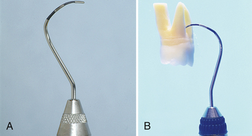
Figure 24-24 A, The No. 2 Nabers probe for detection of furcation areas, with color-coded markings at 3, 6, 9, and 12 mm. B, Probe positioned in a furca for furcation classification.
(A, From Newman MG, Takei HH, Klokkevold PR, Carranza FA: Carranza’s clinical periodontology, ed 10, St Louis, 2006, Saunders.)
Explorer
Design and Use
Clinicians use many diagnostic indicators such as tissue response, bleeding, and radiographic surveys to determine the presence of subgingival deposits. However, tissue response to calculus varies by individual, and radiographs are two-dimensional, making it difficult to visualize flat, burnished calculus deposits obscured by restorations or located on facial or lingual surfaces of teeth. The explorer, designed for adaptation around the tooth, is used to detect and assess the following:
The explorer consists of a very fine, wirelike tip with a sharp point that comes in a variety of lengths, diameters, and bends. Shank diameter is narrow for increased tactile sensitivity. The differences in curvature of the shank, length, and diameter make different explorers useful for specific purposes dependent on tissue, calculus, probing depth, tooth alignment, and other details specific to individual clients.
An explorer is selected for the task it is to perform, as follows:
Heavier-, wider-, or even medium-diameter explorers are best suited for caries detection or exploration around restorations. Such explorers are sturdy and do not deform or bend as they are manipulated under and around caries and metallic margins. Fine, elongated explorers are more difficult to use for caries detection because of the deflection of the instrument during use. Fine-diameter explorers are best suited for subgingival exploration of root structure and identification of calculus and allow for tactile sensitivity. Explorers that are too thin flex and catch in tissue or on root structure in fibrotic or tight areas, relaying incorrect messages about subgingival deposits. For deep periodontal pockets, the explorer should be slightly bent and long enough (such as the Hu-Friedy No. 3-A EXD or the No. EXD 11/12AF) to reach to the apical regions (i.e., 12 mm or deeper). For shallow sulcus areas, CEJs, and under contact areas, a short explorer (such as a pigtail explorer) is easily adapted because it is short and acutely bent. These short, curved explorers are usually double-ended and area-specific—that is, each end works best on specific surfaces of the tooth.Comparisons of these and other explorers are shown in Figure 24-25. Criteria for design, selection, and procedure for use of the explorer are found in Table 24-8 and Procedures 24-1 and 24-3.
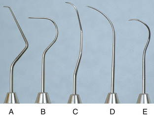
Figure 24-25 Five typical explorers. A, No. 17. B, No. 23 Shepherd’s hook explorer. C, EXD 11/12. D, No. 3. E, No. 3CH pigtail.
(From Newman MG, Takei HH, Klokkevold PR, Carranza FA: Carranza’s clinical periodontology, ed 10, St Louis, 2006, Saunders.)
TABLE 24-8 Explorer Design and Selection
| Instrument Examples | Design, Function, and Recommendation | |
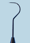 |
No. 23 Shepherd’s Hook Explorer (Supragingival Exploration) | |
| Design | A single-ended explorer with a short lower shank and large rounded hook design. | |
| Function | Supragingival detection of dental caries on all crown surfaces and around restorations. | |
| Recommendation | Not recommended for subgingival calculus or caries detection. | |
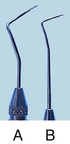 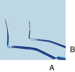 |
Pigtail Explorer (Short and Long) | |
| Design | Double-ended, paired, short, curved explorer. | |
| Function | ||
| Recommendation | Not recommended for subgingival calculus or caries detection in moderate to deep periodontal pockets. | |
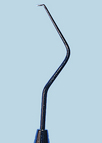 |
No. 17 Explorer (Limited-Use Periodontal Exploration) | |
| Design | A single-ended explorer with a 90-degree angled 2-mm fine tip. | |
| Function | For calculus detection in deep narrow pockets. | |
| Recommendation | ||
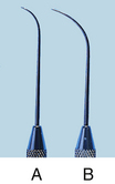 |
No. 3-A Explorer (Periodontal Exploration; Regular Length and Extended Length) | |
| Design | Single-ended, gently curved and tapered explorer. | |
| Function | ||
| Recommendation | Both versions are excellent for caries detection supragingivally and subgingivally. | |
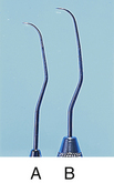 |
11/12 Explorer (Periodontal Exploration; Regular Length and Extended Length) | |
| Design | ||
| Function | ||
| Recommendation | Regular length (A) limits access in deep distal proximal areas of posterior molars; this is corrected with the extended version (B). | |
Procedure 24-3 USE OF THE PERIODONTAL EXPLORER
STEPS
Selecting Correct Working End
Grasp
Fulcrum and Fulcrum Pressure
Insertion and Adaptation
Activation, Direction of Stroke, and Efficiency
The modified pen grasp is used with the dental explorer. When exploring shallow, light, or obvious calculus, the dental hygienist uses a grasp with light to moderate strength. The grasp should become firmer when more pressure needs to be exerted against the tooth or when the dental hygienist needs to distinguish between tooth structure and burnished calculus.
The most important rule governing fulcrum placement when exploring is that the fulcrum be flexible enough to allow the explorer to move from the CEJ to the apex of the pocket with correct insertion and adaptation. Almost any scaling fulcrum could be used as an exploring fulcrum; however, the reverse may not always be true because a scaling fulcrum needs more stability. The exploratory fulcrum could be located close to the area being explored, cross-arch, or extraorally. As the fulcrum moves further from the area being explored, the clinician’s grasp on the instrument handle also moves further away from the working end. This distance does not diminish one’s ability to explore the area, nor does it lessen instrument control. Rather, it enhances access into interproximal regions and deep periodontal pockets.
Tactile Sensitivity
Tactile sensitivity is the ability to distinguish relative degrees of roughness and smoothness on the tooth surface. Experience in detecting light calculus when it is almost completely scaled and in feeling heavy calculus when it has been burnished is a prerequisite for developing tactile sensitivity. The skill may be improved by attention to stroke direction, pressure, type of calculus, and type of root surface being explored.
For calculus detection with an explorer, the practitioner uses a variety of stroke directions (vertical, horizontal, and oblique) to form a basketweave of strokes, as described in a previous section (see Figure 24-14). This is particularly helpful when problems of differentiation between calculus and root structure occur. The dental hygienist should practice different strokes when instrumentation has been particularly difficult in a certain area or when it is necessary to be particularly thorough in calculus detection (such as in a very deep pocket or in an area where there is a periodontal abscess).
Tactile sensitivity also is important in distinguishing between the sulcular soft-tissue wall, the junctional epithelium, and possible osseous exposures. The explorer tip should not stop on the sulcular wall if the instrument is inserted properly and the tip remains well adapted to the tooth surface to the base of the pocket. If the explorer contacts soft tissue, it bounces and snags along the wall until the instrument is properly adapted. As one follows the root of the tooth down to the base of the pocket, the nonkeratinizing junctional epithelium is the base of the pocket. The junctional epithelium feels different at different states of periodontal health, as follows:
In the inflamed state, the junctional epithelium is soft and easily penetrable with a sharp-pointed instrument. If osseous exposure occurs because of heavy instrumentation and exceptionally friable soft tissue, the sensation at the base of the pocket is much like that of heavy, porous calculus. To differentiate calculus from an osseous exposure, the dental hygienist attempts to move around and under the area. If it is calculus, the junctional epithelium is felt under the deposit. If the roughness is an osseous exposure, it is impossible to move the explorer down and under the area.The practitioner uses light pressure when faced with light calculus, little pocket depth, and friable tissue. Increased pressure is required when trying to distinguish burnished calculus or when overinstrumentation may have caused irregular changes in root structure. Pressure should be decreased, however, after thorough root planing to get an overview of the end product.
Sharpening Techniques
Fine explorers become dull through general use and from caries detection in pits and fissures and around restorations. Decreased tactile sensitivity is evident when fine changes in root texture cannot be distinguished or when the explorer glides over the plastic testing stick instead of catching on irregularities. To sharpen the tip of an explorer, the instrument is held with a modified pen grasp, dragged, and rotated along the stone at an angle that keeps the tip and 2 to 3 mm of the terminal end in contact with the stone. Two to three rotations around the tip on the stone sufficiently sharpen the dental explorer (Figure 24-26). Because the periodontal explorer’s length is important, an explorer shortened through wear should be replaced.
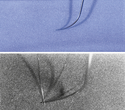
Sickle Scaler
Design and Use
The sickle scaler is designed with either a straight or bent shank (contra-angle) design (Figure 24-27). The straight-shanked sickle scalers are anterior scaling instruments and are often single-ended because the same end may be used mesially and distally (see Procedures 24-1 and 24-4 and Table 24-9). The bent-shanked sickle scalers may be used for anterior as well as posterior areas of the mouth and are usually double-ended, with one end designed for scaling mesial tooth surfaces and the other end for scaling distal tooth surfaces (see Procedures 24-1 and 24-5 and Table 24-10).
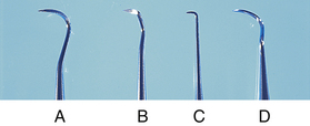
Figure 24-27 Comparison of various sickle scalers. A, Curved anterior sickle. B, Jacquette (double-ended) sickle. C, Morse anterior sickle. D, Posterior sickle.
Procedure 24-4 USE OF ANTERIOR SICKLE SCALER
STEPS
Selecting Correct Working End
Fulcrum and Fulcrum Pressure
TABLE 24-9 Anterior Sickle Scaler Design and Selection
| Instrument Examples | Design, Function, and Recommendation | |
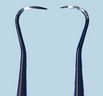 |
||
| Function | ||
| Recommendation | Not recommended for subgingival calculus removal ≥3 mm or root planing. | |
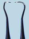 |
||
| Function | Use both ends for anterior supragingival and subgingival (1-2 mm) calculus removal. | |
| Recommendation | Not recommended for subgingival calculus removal ≥3 mm or root planing. | |
Procedure 24-5 USE OF THE POSTERIOR SICKLE SCALER
STEPS
Selecting Correct Working End
Fulcrum and Fulcrum Pressure
TABLE 24-10 Posterior Sickle Scaler Design and Selection
| Instrument Examples | Design, Function, and Recommendation | |
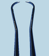 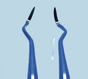 |
S204SD | |
| Design | ||
| Function | ||
| Recommendation | Use for supragingival and subgingival calculus removal (where tissue permits). | |
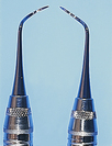 |
SJ 34/35 | |
| Design | ||
| Function | Bent lower shank allows access interproximally and subgingivally in anterior and posterior areas. | |
| Recommendation | Access may be limited owing to size of blade. | |
 |
SCNEVI2 | |
| Design | ||
| Function | Bent lower shank allows ideal access interproximally in anterior and particularly in posterior areas. | |
| Recommendation | Use for supragingival and subgingival calculus removal (where tissue permits). | |
The working end of the sickle scaler is a two-sided blade with the face and two sides forming the two cutting edges. The two sides join together in a V-shape or are slightly flattened, depending on the manufacturer, to form the back of the instrument. Because the sides form a V-shape, this instrument is very sturdy in terms of strength even after it has been sharpened many times. Therefore it is valuable for removal of heavy calculus. However, the extra width from the face to the back of the working end makes it difficult to close the angulation of most sickles without traumatizing the sulcular epithelium with the V-shaped back during subgingival instrumentation. This problem is accentuated with large sickle scalers.
There are medium posterior sickle scalers with a curved blade contra-angle design, which are very effective for moderate to heavy subgingival calculus removal in anterior and posterior areas. Small straight-shanked sickle scalers such as the Morse scaler (see Figure 24-27, C) cause even less trauma and may be easier to use for subgingival scaling in tight anterior areas.
The tip of the sickle scaler always ends in a sharp point. This tip is the major difference between a sickle scaler and a curet, especially when comparing the curved blade, contra-angle designed sickle scalers with a curet. The advantage of the sickle scaler is its ability to reach between very tight contacts. The disadvantage is that the sharp tip and straight cutting edge do not adapt well to rounded tooth surfaces; some part of the instrument is always off the tooth. This problem of adaptation and a V-shaped back imposing on the sulcular wall makes the sickle scaler largely a supragingival scaling instrument. Only in situations of moderate to heavy subgingival calculus and very loose tissue may the sickle scaler be used subgingivally. Because of the need to control adaptation of the toe and cutting edge of this instrument, instrumentation techniques for sickle scalers require a stable modified pen grasp and fulcrum relatively close to the area being scaled. A pull stroke action in a vertical or oblique direction is made against the tooth surface.
Sharpening Technique
Sharpening the sickle scaler requires the stone to remain stationary and the instrument to move over the stone. The stone is secured with the nondominant hand, the instrument held with a modified pen grasp, and the lateral surface positioned at an angle of 100 to 110 degrees to the stone. The entire lateral surface on a flat-surfaced sickle scaler lies against the stone. For curved sickle scalers, small portions of the lateral surfaces are sharpened at a time, beginning from the portion nearest the shank. The working hand is stabilized with a fulcrum on the stone, and short, firm strokes are applied for sharpening. Because the sickle scaler has two cutting edges, the instrument is turned over and the procedure is repeated for the other lateral surface of the blade. Occasionally the face of the sickle scaler is sharpened. For this surface, the stone either must be positioned near the edge of the table or held up so that the entire face may be sharpened against the surface of the stone. Tests for sharpness include the visual or tactile methods described earlier.
Universal Curet
Design and Use
The universal curet, used for supragingival and subgingival scaling and root planing in all areas of the mouth, is designed with paired mirror-image working ends placed on a single-handle instrument. These working ends are identified by the name of the manufacturer, inventor, or school that developed the particular design. On double-ended instruments the name is followed by two numbers, each designating a working end (e.g., Columbia 13/14) (see Procedures 24-1 and 24-6 and Table 24-11).
Procedure 24-6 USE OF UNIVERSAL CURET
STEPS
Selecting Correct Working End
Grasp
Insertion, Adaptation, and Angulation
TABLE 24-11 Universal Curet Design and Selection
| Instrument | Design, Function, and Recommendation | |
| Posterior and Anterior Application | ||
| Design | ||
| Function | ||
| Recommendation | May be useful in posterior areas of the healthy mouth. | |
| Posterior Application | ||
| Design | ||
| Function | ||
| Recommendation | ||
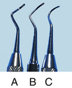
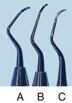
The universal curet blade has two lateral surfaces that form two parallel cutting edges on both sides of the flat face (inner surface) of the blade. The two cutting edges form a rounded tip (or toe) at the terminal end of the blade. The lateral surfaces converge to form the rounded back of the blade. This design reduces the chances of subgingival trauma to both sulcular tissues and tooth structure. Both cutting edges of a universal curet blade are parallel and curved upward toward the toe of the blade (Figure 24-28). The curvature of the blades defines the areas in which the instrument is most useful.
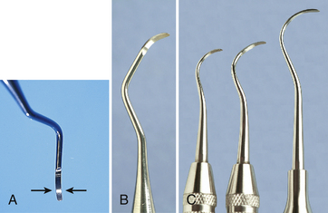
Figure 24-28 A, Both cutting edges of a universal curet blade are parallel and curved upward toward the toe of the blade. B, Columbia No. 4R-4L universal curet. C, Younger-Good No. 7-8, McCall’s No. 17-18, and Indiana University No. 17-18 universal curets.
(B and C, From Newman MG, Takei HH, Klokkevold PR, Carranza FA: Carranza’s clinical periodontology, ed 10, St Louis, 2006, Saunders.)
The face of the universal curet blade is positioned at a 90-degree angle to the lower shank. There is a bend above the lower shank so that the handle is not parallel with the lower shank (Figure 24-29). Therefore, to close angulation, the handle and lower shank of the universal curet must be tilted slightly toward the tooth (Figure 24-30).
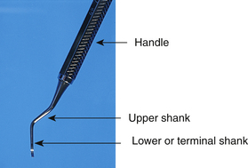
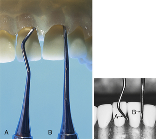
Figure 24-30 To close angulation with the universal curet (A), the handle is tilted toward the tooth surface more than is necessary with the Gracey curet (B). This angulation is a result of the differences in the relationships of the faces of the blades and the lower shanks of the two instruments.
One double-ended universal curet can be used to scale all areas of the dentition of a periodontally healthy mouth. Scaling with a universal curet is more difficult with increased pocket depth. In these cases, combinations of universal curets may be necessary to extend the reach. The Columbia 13/14, for instance, is a short, acutely curved universal curet. This instrument works well in anterior areas or in areas with slight to moderate probing depths and is often paired with the Columbia 4R/4L for use in deeper, more posterior areas. The Columbia 2R/2L is even longer than the Columbia 4R/4L and is ideal for areas of deep facial or lingual pocket depth (Figure 24-31).
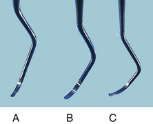
Blade Selection for Posterior Teeth
Because the ends of a double-ended universal curet are mirror images, they are used in the same manner but for mirror-image surfaces. This application is especially true in posterior regions. If, for example, one end is used for the distal interproximal surface from the facial aspect, then the opposite end is used for the mesial interproximal surface from the lingual aspect. The end that works best for the straight facial aspect is the same end used for the mesial surface. The end that works best for the straight lingual aspect is the same end used again for the mesial aspect from the lingual surface. Therefore the working ends of the universal curet are not the same for the facial and lingual surfaces in posterior areas.
Blade Selection for Anterior Teeth
In anterior areas the correct side of the instrument is not so critical. Both cutting edges of the universal curet blade may be used for scaling and root planing in anterior areas. Only the angulation or the degree to which the blade is open is different from one end to the other when the ends of the instrument are exchanged. The cutting edge that offers a more open angulation is better for traction and reduces calculus burnishing. However, the type of tissue is a major consideration in selecting the cutting edge for anterior scaling. If the tissue is tight and fibrotic and the pocket depth very shallow, the dental hygienist should choose the cutting edge that offers a blade angulation closer to the tooth surface. If the tissue is loose, the cutting edge that offers a more open angulation, better traction, and less burnishing action is a better choice because there is less chance of inadvertent soft-tissue curettage against the wall of the pocket with the opposite cutting edge.
Curet Selection
Because the curets are critically important instruments in scaling and root planing, the dental hygienist needs to select the best instruments made from many different manufacturers. Universal curets are made in several varieties of metals, each with specific strengths and weaknesses (see the section on the working end in this chapter). The shank strength and thickness of the blade when new are also factors to consider in instrument selection.
The practitioner uses a modified pen grasp and selects an intraoral or extraoral fulcrum based on the techniques used in customizing the stroke to a particular tooth surface. Basically, the more periodontally involved the tooth, the more the dental hygienist will find the need to fulcrum away from the working site. A working stroke is initiated in a vertical, horizontal, or oblique direction.
Sharpening Techniques
A curet has lost sharpness if the following occur:
The curets angulation must be further closed for the instrument to maintain a working relationship with the tooth surface.The more accurately the curet has been sharpened (i.e., the angulation of the lateral surface to the face of the blade is correct and a definite cutting edge has been established), the longer the curet remains sharp. Accurate sharpening lengthens the time interval between sharpening and thus preserves the metal. Because the cutting edge of the universal curet is two-sided and includes the rounded toe, sharpening includes all of these areas. It is recommended, however, that the toe of the universal curet be preserved as long as possible because the toe itself is not usually used in instrumentation except occasionally under the floor of furcations or under tooth contacts. When the toe is sharpened each time the lateral surfaces are sharpened, there is unnecessary reduction of the length of the blade, eventually making the instrument inaccessible to interproximal areas. Both sides of the blade should be sharpened if dull.
Sharpening the Lateral Sides
The universal curet may be sharpened in two ways, as follows:
Moving the instrument over the stone requires the stone to be placed on a stable surface such as a tabletop, the curet held in a modified pen grasp, angulation of the face to the surface of the stone positioned between 100 and 110 degrees, and the curet blade moved at this angulation from the lower third of the blade to the midline of the toe. Each side of the universal curet blade is sharpened as needed. Moving the stone over the blade requires the stone to be held in the dominant hand and the instrument held with a palm-thumb grasp secured against a firm surface (tabletop) or the elbow drawn close to the body for support. The instrument is held with the face of the blade parallel to the floor and the stone positioned on the lateral surface at a 100- to 110-degree angle. The stone is moved with short, light to firm vertical strokes, depending on the amount of sharpening needed, and is slowly passed across the entire cutting edge at consistent angulation. It is important to maintain consistent angulation for an evenly sharpened blade. For this to be accomplished, the stone should not be lifted from the blade; both the upward and downward strokes are used for sharpening. Even pressure should be used along the cutting edge to prevent changing the normal shape of a curet blade.Figure 24-32 illustrates the cross-sectional views of curet blades resulting from common sharpening errors. The most common error is to increase the pressure as the stroke nears the toe, producing a blade with converging lateral sides connected by a point instead of parallel lateral sides connected by a rounded toe (Figure 24-33). The method of moving the stone over the instrument is slightly easier than moving the instrument, because as the stone is moved a light film of lubricant and/or sharpening byproducts (sludge) accumulates on the surface of the face, and angulation of lateral surface to stone is easier to visualize. The last stroke(s) should be in a downward motion toward the back of the instrument to reduce the possibility of a wire edge on the face of the blade. Figure 24-34 compares both methods of sharpening the universal curet.
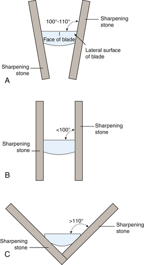
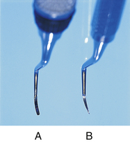
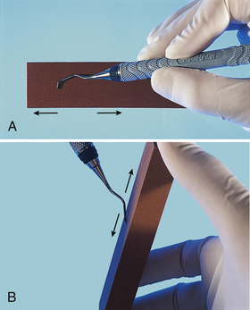
Sharpening the Face
The face of the curet blade may be sharpened with a cone-shaped sharpening stone, the rounded side of a sharpening stone, or a mounted rotary stone. Often these methods produce unreliable results because it is difficult to maintain even pressure across the face. If too much metal is removed (as with the rotary stone) the strength of the blade from face to back is weakened. This dimension from face to back is significant because it is an important factor in providing strength to an instrument that uses a pulling action, as does the curet. When all sharpening has been completed, the instrument is wiped with a 2-inch × 2-inch gauze square and tested for sharpness.
Area-Specific Curets
Design and Use
The designation of area-specific curets means that each of the instruments in the collection is designed to scale specific areas of the mouth (e.g., anterior versus posterior) and specific tooth surfaces (e.g., mesial versus distal). Gracey curets are particularly effective for instrumenting teeth with slight to severe periodontitis in individuals who require therapeutic scaling and root planing by quadrant or sextant.
Gracey curets consist of nine mirror-image pairs of instruments: the Gracey 1/2, 3/4, 5/6, 7/8, 9/10, 11/12, 13/14, 15/16, and 17/18. Although Gracey curets were designed to be used in designated areas of the mouth (area-specific), it is possible to use Gracey curets in a variety of places. Because of this, dental hygiene educators often provide instruction for full-mouth periodontal instrumentation using a select few of the entire collection. The instruments selected usually represent basic anterior-, posterior-, mesial-, and distal-specific instruments. An example of such a selection is the Gracey 5/6, 7/8, 11/12, and 13/14 (Figure 24-35, A and B). Table 24-12 outlines the variations of design in area-specific curets. Table 24-13 summarizes the design of and selection criteria for the use of each of the Gracey area-specific curets. Procedures 24-1 and 24-7 outline the steps for their use.
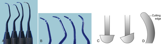
Figure 24-35 A, Gracey curets 5/6, 7/8, 11/12, and 13/14. B, Close-up of Gracey curets 5/6, 7/8, 11/12, and 13/14. C, Face of a universal curet is at 90 degrees to its shank (left), whereas the face of a Gracey curet is offset, forming a 70-degree angle with its shank (right). D, Determining the correct cutting edge of a Gracey curet. When viewed from directly above the face of the blade, the correct cutting edge is the one forming the larger outer curve on the right.
(C and D, From Newman MG, Takei HH, Klokkevold PR, Carranza FA: Carranza’s clinical periodontology, ed 10, St Louis, 2006, Saunders.)
TABLE 24-12 Area-Specific Curet Design Variations (see Figure 24-38)
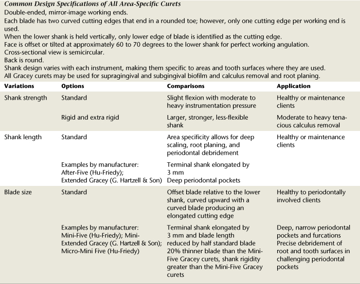
TABLE 24-13 Area-Specific Curet Design and Selection
| Instrument | Design and Selection | |
|---|---|---|
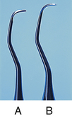 |
||
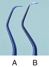 |
||
| (See comparison above with Gracey 1/2) | ||
| (See comparison above with Gracey 3/4) | ||

 |
||
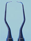
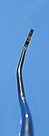 |
||
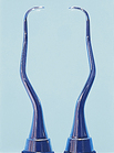
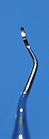 |
||
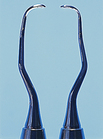
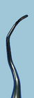 |
||
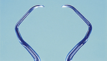
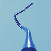
Procedure 24-7 USE OF AREA-SPECIFIC CURETS
STEPS
Selecting Correct Working End
Grasp
Fulcrum and Fulcrum Pressure
Insertion, Adaptation, and Angulation
The basic reason Gracey instruments are ideal for instrumenting periodontitis-affected teeth lies with the relationship of the face of the blade to the lower shank. The Gracey curet is honed so that the face is “offset” or at an angle to the lower shank. (The lower or terminal shank is the last bend of the shank closest to the working end.) Whereas the universal curet’s face is at 90 degrees, the Gracey curet is at a 60- to 70-degree angle to the lower shank (see Figure 24-35). With this angle of the face to the lower shank, the lower shank is parallel to the tooth surface being scaled when proper angulation of the cutting edge to the tooth surface is achieved. This automatically places the blade against the tooth at a 40-degree angle. Therefore, when using Gracey curets, it is important to observe the relationship of the lower shank to the surface being scaled to help determine if correct angulation is achieved.
Like the universal curet, the Gracey curet has two bladed sides that come together to form a rounded toe. But unlike the universal curet, which has two useful cutting edges because both blades run parallel to each other, the Gracey curet has only one designated cutting edge. The correct cutting edge is determined by examining the curvatures of the blade. The blade of the Gracey curet not only is bent in a curve, but also is bent so that one cutting edge is elongated. This longer curved side of the Gracey curet, as shown in Figure 24-36, is the correct cutting edge. When the lower shank is held perpendicular to the floor with the face of the blade up, this cutting edge is slightly lower than the shorter edge. Together with the basic bend of the blade, this elongation makes Gracey instruments particularly efficient in adapting to root morphology.
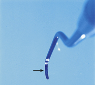
Sharpening Technique
The major difference between sharpening the Gracey and the universal curet is that the Gracey curet blade is offset. Both instruments may be sharpened with movement of the instrument or the stone. Grasp positions, angulation of 100 to 110 degrees, and movement across the blade are the same for the Gracey and universal curets. The Gracey curet blade face is offset at 60 to 70 degrees to the shank (as opposed to 90 degrees for the universal curet), which opens the angle of the stone on the Gracey when the lower shank of each is held perpendicular to the floor. When the Gracey curet blade face is held parallel with the floor (like the universal curet), the stone is positioned like the universal curet, but the handle and shank of the Gracey curet are tilted away from the stone and not perpendicular to the floor. Figure 24-37 shows a comparison of stone and handle when the faces of a Gracey and a universal curet are held parallel to the floor. On the Gracey curet, only the lower, longer cutting edge from the area where blade sharpness begins and occasionally around the toe is sharpened. After sharpening procedures, the blade should be tested for sharpness and wiped clean before instrumentation. These principles of sharpening also apply to the variations of the Gracey curet that follow.
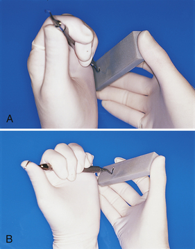
Figure 24-37 Comparison of handle position of a universal curet (A) and a Gracey curet (B) when the face of the blade is held parallel to the floor for sharpening (from the point of view of the clinician looking down).
Note that curets are now available in new materials that eliminate the need for sharpening (XP Technology, American Eagle Instruments) or reduce the need for sharpening (EverEdge Technology, Hu-Friedy Manufacturing). Currently there is limited research evidence on the advantages of instruments made with these materials and ones currently under development. Dental hygienists need to use evidence-based decision making to ensure the best outcome for their clients.
Extended-Shank Curets
Design and Use
The Gracey extended series is a modified set of Gracey curets that are exactly like the traditional Gracey curets except that the lower shank of each instrument is 3 mm longer (Figure 24-38). Extended Gracey curets are particularly useful in areas with significant pocket depth or recession. Hu-Friedy calls its extended Gracey curet the Hu-Friedy After-Five, and G. Hartzell & Son uses the name Extended Gracey curet. Some manufacturers offer a blade thinned by 10% for ease in gingival insertion and to reduce tissue distention. Because the shanks are longer than those of the traditional Gracey curets, they often require an extended fulcrum such as an opposite arch, cross-arch, or extraoral fulcrum. Reinforcement with the nondominant hand often is helpful for additional control.
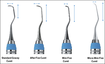
Minibladed Curets
Design and Use
Another variation of the basic curet is the Gracey mini-curet, which has a terminal shank that is 3 mm longer than and a working blade that is half the length of the traditional Gracey curet (Figure 24-39). Like the extended-shank curets, each manufacturer labels the mini series differently: Hu-Friedy calls their mini–Gracey curet the Hu-Friedy Mini-Five, and G. Hartzell & Son uses the name Mini-Extended Gracey curet. The minibladed Gracey curet is particularly useful in areas of narrow, deep pocketing in which it is impossible to vertically insert a long, regular blade straight down into the pocket or vertically instrument interradicular root surfaces of furcations. The options in these situations are to use a horizontal stroke with the toe directed to the junctional epithelium or to use a shortened instrument such as a mini-curet with a vertical stroke. This instrument is also used in rounded convexities or concavities found going into and out of root depressions and around line angles.
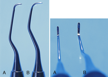
Micro Mini-Five Gracey Curets
Design and Use
Another variation of the mini-curet series is the micro series, with ultra slender blades and shank rigidity, manufactured with a special metal (EverEdge Technology) that decreases the amount of sharpening required. Micro Mini-Five Gracey curets (area-specific) are designed to precisely debride root and tooth surfaces even in the most challenging periodontal pockets. The blades are 20% thinner than Mini-Five Gracey curets to further reduce tissue distention and ease subgingival insertion. Terminal shanks are elongated for deep access into pockets; they have slightly increased shank rigidity compared with the Mini-Five Gracey curet. Because of the Ever Edge Technology, the instruments keep their sharp edge longer, and sharpening time is reduced (Figure 24-40).
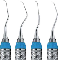
Sharpening Technique
See the discussion of sharpening technique in the section on area-specific curets.
Shank Design
Certain manufacturers make the Gracey curet with a rigid and even an extra-rigid shank that does not dissipate the power used in a working stroke. This design differentiates the rigid Gracey from the finishing Gracey curet, which has a more flexible shank. The rigid shank is essential when performing heavy scaling and root planing. It is also quite effective when less lateral pressure is required. The rigid shank does not diminish tactile sensitivity. Rather, it enhances control and reduces energy needed to make any direction of stroke under any degree of pressure.
Because the finishing Gracey curet has a more flexible shank, it bends under pressure. A significant amount of lateral pressure is lost in the flexion that occurs under firm working strokes. Therefore this instrument is indicated for light scaling and root planing.
The basic modified pen grasp and fulcrum placement techniques used with the universal curet are also used with Gracey curets. Instrumentation in deep periodontal defects or when using elongated, specialized Gracey curets requires the use of extended fulcrums and reinforcement scaling techniques.
Hoe Scaler
Design and Use
The hoe scaler is used for heavy supragingival calculus removal. Because of design limitations, it is best used in subgingival areas where access is easy, such as facial and lingual surfaces (as opposed to interproximal surfaces), and when tissue tone is loose and edematous. It is not well suited for fine subgingival scaling and root planing.
The hoe has paired working ends, and a set of four working ends is needed to instrument each tooth surface. Shank length on a hoe may vary from long to short, and the shank may also be bowed in a slight or more acute angle (Figure 24-41). These variations in shank length and angle help determine the best areas in which to use the hoe scaler. The longer and more angled the shank, the better suited the instrument is for posterior areas. The shorter, less acutely angled shank is better suited for anterior areas.
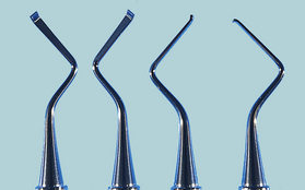
The terminal end of the blade is bent to a 99- to 100-degree angle, and the tip is beveled at a 45-degree angle to form a single cutting edge. The upper edge forms the actual cutting edge because the hoe scaler is a pull instrument. The cutting edge is a straight, thick, short blade with two sharp corners on each end.
When the instrument is inserted subgingivally and the blade is well adapted to the tooth surface, the side of the shank should form a two-point contact with the tooth surface. This improves stability and leverage during instrumentation.
The limitations of the hoe scaler begin with the bow or angle in the shank. This characteristic angle of hoe scalers seriously limits one’s ability to instrument to the base of pocket depth unless the tissue is very loose. The short, straight, bulky blade also poses a problem of adaptation when curved root surfaces are instrumented. Tactile sensitivity also is limited.
The modified pen grasp should be used with the hoe scaler. A fulcrum close to the immediate working area is suggested for maximal control. The cutting edge is positioned under the deposit, and a pull stroke in a vertical direction is applied to remove the calculus.
Sharpening Techniques
The hoe is sharpened by placing a stationary stone on a tabletop and positioning the entire blade surface on the stone. It is important to maintain the 45-degree bevel. The instrument is held with a modified pen grasp and stabilized with a fulcrum on the stone. Movement of the instrument across the stone is made in short, moderate pull strokes. A push-pull or grinding stroke is not recommended. The corners at each cutting edge are occasionally rounded with light rolling strokes to prevent grooving or gouging of the tooth structure and soft-tissue injury. The hoe is tested for sharpness on a testing stick and wiped of debris before instrumentation.
File Scaler
Design and Use
The file scaler, which is similar in design to the hoe scaler, is a pull instrument used supragingivally or subgingivally for crushing or breaking up heavy subgingival calculus. It consists of a series of miniature hoe blades on a pad attached to the shank. Each blade is bent at an angle of 90 to 105 degrees from the shank. Each blade possesses sharp corners that together pose a hazard to tooth structure if adaptation is not maintained during stroke activation. These corners may be slightly rounded with a sharpening stone before the file is used (Figure 24-42).
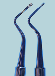
Roughening up the surface of tenacious, burnished calculus helps to prepare the surface, making it easier for the curet to latch onto to break the piece away from the tooth. Because this instrument has many of the limitations of the hoe scaler, it should not be used for definitive subgingival scaling and root planing.
The instrument may be double-ended or single-ended. The file has paired ends, and, as with the hoe, four working ends are needed to instrument each of the four surfaces of a tooth (mesial, distal, facial, and lingual). As with the hoe, the longer, more angled shanks are better suited for posterior areas. The shorter, less angled shanks are better suited for anterior areas. The shank of the file is fairly rigid, which is advantageous when pressure is applied against the tooth.
The pad or base of the working end of the file may come in a variety of shapes (round, oval, or rectangular) and in numerous sizes, depending on the manufacturer. It is obvious that the larger the base, the more difficult it becomes to adapt to rounded root surfaces. The size, adaptation, and bend of the shank create problems for working in interproximal areas. As with the hoe, the easiest areas are the facial and lingual surfaces and mesial and distal surfaces, where there are no contacts. Loose, edematous tissue is necessary for reaching areas close to the base of the pocket.
The modified pen grasp should be used with the file scaler with a fulcrum close to the immediate working area and the entire series of blades positioned against tooth surface.
Sharpening Techniques
The file is a difficult instrument to sharpen because of the miniature size of each blade. Sharpening may be accomplished with a tanged file sharpener positioned against each small, flat-bladed surface (Figure 24-43). For the sharpening procedure, the instrument is stabilized on a firm surface (tabletop) and the practitioner stabilizes the working hand near the instrument on the tabletop to perform light, short, push-pull strokes across each blade. Consistently good results are difficult to achieve when sharpening this instrument.
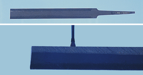
Chisel Scalers
Design and Use
The chisel scaler is a double-ended instrument with either a straight or a curved shank. The blade is continuous with the shank, and the narrow cutting edge is formed with the tip beveled at a 45-degree angle (Figure 24-44). This instrument should be used only on heavy interproximal ledges of calculus, especially on lower anterior teeth. It should not be used for scaling and root planing procedures. The chisel is very limited and is not often used by dental hygienists because of the better versatility and advantages of other scaling instruments.
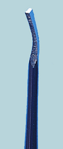
The chisel scaler is a push instrument. To avoid unnecessary trauma to soft tissues, it should be used only in a horizontal direction. The instrument should be stabilized against a tooth structure and used with a pushing motion to dislodge heavy interproximal, facial, and lingual calculus from mandibular anterior teeth. Because the corners of the chisel are sharp, care should be taken to keep the blade evenly on tooth structures during stroke activation. A modified pen grasp with an intraoral fulcrum close to the working area aids the practitioner in stabilizing this instrument. Sharpening objectives and procedures for the chisel scaler are similar to those for the hoe scaler.
Furcation Instruments
See the discussion of furcation involvement in Chapter 17, and see Chapter 26 for a review of furcation anatomy.
Design and Use
Instruments specially designed to access small areas such as furcations and other concave root surfaces are available from a number of manufacturers. Generally, the purpose of these instruments is to remove light deposits and finish surfaces in narrow, inaccessible areas. They are not for heavy calculus removal. Although these instruments are not truly scalers, curets, or files, some are named as such (e.g., Diamond Tec File Scalers, Hu-Friedy Manufacturing; Diamond-Tip Curettes, Brasseler USA; Diamond Files, G. Hartzell & Son; Furcation Files, LM-Instruments). Available as a buccal lingual or a mesial distal instrument, the Quetin (pronounced kee-tin) furcation curets (Hu-Friedy) are small hoes with semicircular blades designed to scale a furcation ceiling or floor. The LM_Furcator (LM-Instruments) has the following designs to reach concave root surfaces (Figures 24-45 and 24-46).
Buccal and lingual designs (e.g., SDCN7, Hu-Friedy; 209.F1 and 209.F2, Brasseler USA) have paired ends and as such are universal instruments. Mesial and distal diamond-coated working ends have a concave mesial end and a convex distal end on one instrument (Hu-Friedy), or concave mesial and distal ends on one instrument (Brasseler USA). These designs are for adaptation to line angles and deep developmental grooves and for final debridement and polishing of root surfaces and furcations.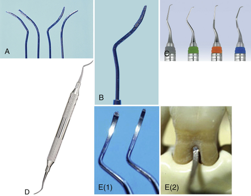
Figure 24-45 Furcation instruments. A and B, Brasseler diamond-coated instruments. C, Diamond Tec file scalers. D, Diamond Furcation file No. DF1/2. E, Quetin furcation curet by Hu-Friedy.
(C, courtesy Hu-Friedy, Chicago, Illinois. D, courtesy G. Hartzell & Son, concord, California. E, From Pattison A, Matsuda S, Pattison G: Periodontal instrumentation, ed 3, Upper Saddle River, NJ, Prentice Hall [in press].)
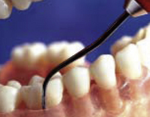
Figure 24-46 Placement of SDCN7 Diamond Tec file scaler into a mandibular furcation.
(Courtesy Hu-Friedy Manufacturing, Chicago, Illinois.)
Instruments with diamond-coated working ends are used with both push and pull strokes with very light pressure in a multidirectional manner. Used in a sanding motion, such instruments remove flat, smooth calculus and significantly reduce root overinstrumentation that might have resulted with curet use.
DENTAL PERIOSCOPY
Fiberoptic imaging of the periodontal pocket, called dental perioscopy, allows subgingival visualization for diagnosis as well as treatment (DentalView Perioscopy). Using dental perioscopy, the clinician magnifies, visualizes, and accesses deep subgingival calculus, root fractures, and the periodontal pocket’s internal wall. Magnification is from 24× to as high as 46×, depending on the distance between the object and the lens. Under endoscopic magnification, ledges of black calculus are actually white, porous, and crystalline in appearance, and sheets of subgingival calculus may occur in colors from golden brown to black.
The system is composed of a disposable sterile sheath that houses a fiberoptic endoscope, provides continuous irrigation, attaches to modified periodontal assessment and treatment instruments, and has a metal soft-tissue shield that keeps the soft tissue away from the tube (Figure 24-47). The actual size of the handheld sheath and instrument with proper hand grasp is shown in Figure 24-48. The system includes a flat-panel liquid crystal display (LCD) color monitor and a small footprint transport system (Figure 24-49). A composite video-out source connection allows users to employ a digital system to record and later view endoscopic images if desired.
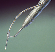
Figure 24-47 The endoscope explorer with sheath and fiberoptic bundle in the “thistle” adapter.
(Courtesy DentalView, Irvine, California.)
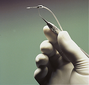
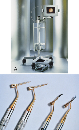
Figure 24-49 A, The DentalView 2 endoscope with an image of the subgingival sulcus on the monitor screen. B, Viewing periodontal explorers for the perioscopy system.
(A, Courtesy DentalView, Irvine, California. B, From Newman MG, Takei HH, Klokkevold PR, Carranza FA: Carranza’s clinical periodontology, ed 10, St Louis, 2006, Saunders.)
This system of visualization during root surface instrumentation improves clinical assessment of results over traditional tactile methods of assessment. Clinicians experienced with the system indicate an extraordinary ability to visualize and instrument deep, narrow pockets, depressions, line angles, and furcations. The process also is educational, because clients see the intricacies of their disease and treatment on the monitor and judge the effectiveness of oral self-care procedures. Figure 24-50 illustrates a cross-sectional view of the endoscope in place subgingivally.
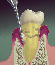
Figure 24-50 Diagrammatic illustration of the endoscope’s explorer examining the subgingival root surface and calculus deposits.
(Courtesy DentalView, Irvine, California.)

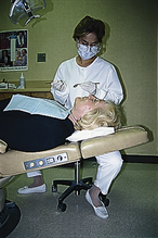

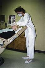
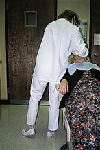
Periodontal instrumentation with visualization is significantly more accurate and specific than instrumentation without visualization. In addition to traditional treatment instruments, nontraditional periodontal instruments such as diamond-coated instruments (see Figure 24-45) are being used with success when the clinician is able to view areas of burnished calculus. Even with visualization, successful instrumentation is still dependent on the clinician’s ability to use a variety of fulcrums, stroke directions, and periodontal instruments.
REPETITIVE STRAIN INJURIES (SEE CHAPTER 9)
The dental hygienist uses protective strategies of positioning and instrumentation to prevent or lessen risk of injury (see the discussion of RSIs in Chapter 9). The term protective scaling (established by M. Tsutsui) denotes operator and client positioning, fulcrums, and reinforcements that seek to minimize practitioner injury (Procedure 24-8). Protective techniques of operator and client positioning and instrumentation offer viable solutions to the problems of occupational injury to dental hygienists.
Procedure 24-8 BASIC OPERATOR POSITIONING STRATEGIES FOR PROTECTIVE SCALING
STEPS
Maintain a straight lower back for much of the time during the appointment.
From this position, lean over client, concentrating more total body effort to control scaling actions.
To reduce the possibility of developing RSIs, the dental hygienist must look at the ergonomics of the work environment—beginning with basic operator positioning, client positioning, grasp, and fulcrum—and monitor the effects of instrumentation on practitioner hand, wrist, elbow, shoulder, and back movements (Table 24-14 and see Chapter 9, Figure 9-2). Self-evaluation, done at any time during the instrumentation process, requires that the practitioner be aware of areas of stress in the working hand, arm, or spine. If it is possible to transfer or equalize the stress of working from the hand and wrist to include the arm or even the shoulder, doing so will minimize occupational injury.
TABLE 24-14 Self-Evaluation of Basic Operator Technique
REINFORCEMENT SCALING TECHNIQUES
Reinforcement scaling is used to gain additional stability and control of the instrument when scaling with both the intraoral and extraoral fulcrums. In most cases, reinforcement scaling means that the nondominant hand is used for additional support of the instrument instead of holding the mouth mirror. In some cases (see Figure 24-18, C) it is still possible to hold the mouth mirror and provide reinforcement with the nondominant hand. Reinforcement scaling is protective to the practitioner.
The added support from reinforcement may come from the index finger, thumb, or thenar region (radial palm or fleshy mass on lateral side of palm) of the nondominant hand. The dominant hand must continue to play the major role in adapting and angulating the blade against the tooth surface. It also must exert control over the direction in which the instrument is pulled over the tooth. The benefits of reinforcement are as follows:
Provides additional lateral pressure in the same direction in which the dominant hand’s fingers are directing pressure Supports the thenar region of the dominant hand, which provides protective qualities during often strenuous and intensive instrumentation processesThe beneficial aspects of reinforcement scaling are found only when the operator uses both intraoral and extraoral fulcrum techniques. The names of the reinforcements tell the operator where the reinforcements originate. The placement of the index finger and thumb may be on or around the instrument between the working end and the dominant hand. The reinforcing thumb also may be positioned against the dominant thumb or thenar region for support and operator comfort. Examples of reinforcement scaling in selected areas of the mouth are shown in Figures 24-56 to 24-60.
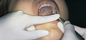
Figure 24-56 Index finger reinforcement. Left maxillary mesial surface from lingual approach. Operator is at the 8-o’clock to 9-o’clock position. The Gracey curet 11/12 is being used. Position of the working hand is extraoral fulcrum, palm down. The position of the reinforcement hand shows the index finger on the instrument applying pressure in the same direction of lateral pressure in which the dominant hand is working.
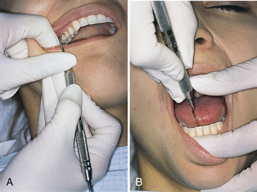
Figure 24-57 Thumb reinforcement. A, Right maxillary posterior mesial surface from facial approach. Operator is at the 8-o’clock to 9-o’clock position. The Gracey curet 11/12 is being used. Position of the working hand is extraoral fulcrum, palm up. The position of the reinforcement hand shows the index finger retracting buccal mucosa, and the thumb on instrument applying pressure in the same direction of lateral pressure in which the dominant hand is working. B, Mandibular anterior lingual interproximal surface. Operator is at the 12-o’clock position. The Gracey curet 7/8 is being used. Position of the working hand is opposite arch fulcrum. The position of the reinforcement hand shows the index finger retracting the lower lip, and the thumb applying pressure in the same direction of lateral pressure in which the dominant hand is working or supports in upward movement.
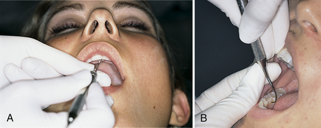
Figure 24-58 Index finger–thumb reinforcement. A, Maxillary anterior lingual interproximal surface. Operator is at the 8-o’clock to 9-o’clock position. The Gracey curet 5/6 is being used. Position of the working hand is extraoral fulcrum, palm up. The position of the reinforcement hand shows the index finger under instrument, thumb on top of instrument in pinchlike grasp. B, Mandibular right posterior mesial surface from lingual approach. Operator is at the 1-o’clock position. The Gracey curet 11/12 is being used. Position of the working hand is opposite arch fulcrum. The position of the reinforcement hand shows the index finger under the instrument, thumb on top of the instrument in pinchlike grasp.
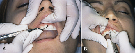
Figure 24-59 Thenar support reinforcement. A, Maxillary anterior facial surface from labial approach. Operator is at the 12-o’clock position. The Gracey curet 7/8 is being used. Position of the working hand is intraoral fulcrum close to working area. Position of the reinforcement hand shows the index finger retracting the lip, and thumb supporting working thumb. B, Maxillary anterior interproximal surface from labial approach. Operator is at the 8-o’clock to 9-o’clock position. The Gracey curet 7/8 is being used. Position of the working hand is intraoral fulcrum close to the working area. The position of the reinforcement hand shows the index finger retracting the upper lip, and thumb supporting working thumb near thenar area.
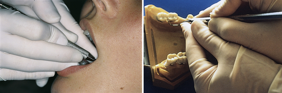
Figure 24-60 Index thenar reinforcement. Mandibular right posterior distal line angle from lingual approach. Operator is at the 8-o’clock to 9-o’clock position. The Gracey curet 13/14 is being used. Position of the working hand is fulcrum same quadrant as area being scaled. Position of the reinforcement hand is index finger on instrument, and thumb of reinforcement hand along thumb of working hand.
CLIENT EDUCATION TIPS
LEGAL, ETHICAL, AND SAFETY ISSUES
KEY CONCEPTS
Basic dental hygiene assessment instruments include the mouth mirror, periodontal probe, and explorer. Shape, length, and markings of periodontal probes and explorers vary; selection is dependent on the client’s oral disease status and clinician preference. Periodontal hand instruments are available, and selection is dependent on function, the client’s periodontal health status, and clinician preference and experience. Major classifications in blade design, shape, and size dictate use and effectiveness of periodontal instruments; small variations in periodontal treatment instruments in shank length, curvature, and flexibility profoundly affect use and effectiveness. Proper grasp and fulcrum placement are essential for safe and effective periodontal instrumentation technique. Effective periodontal instrumentation technique encompasses a complex set of skills, assessment of relationships, and movements with the goal of performing subgingival scaling and root planing to treat and arrest periodontal disease.CRITICAL THINKING EXERCISES
ACKNOWLEDGMENTS
The authors acknowledge Peggy T. Tsutsui for her past contributions to this chapter.
Instruments and photos generously provided courtesy Brasseler USA; G. Hartzell & Son; Hu-Friedy Manufacturing; Florida Probe Corporation; American Eagle Instruments; Miltex; Paradise Dental Technologies; LM-Instruments; and Premier Dental Products.
Refer to the Procedures Manual where rationales are provided for the steps outlined in the procedures presented in this chapter.
Visit the  website at http://evolve.elsevier.com/Darby/Hygiene for competency forms, suggested readings, glossary, and related websites.